JP7370552B1 - mounting pin - Google Patents
mounting pin Download PDFInfo
- Publication number
- JP7370552B1 JP7370552B1 JP2023111078A JP2023111078A JP7370552B1 JP 7370552 B1 JP7370552 B1 JP 7370552B1 JP 2023111078 A JP2023111078 A JP 2023111078A JP 2023111078 A JP2023111078 A JP 2023111078A JP 7370552 B1 JP7370552 B1 JP 7370552B1
- Authority
- JP
- Japan
- Prior art keywords
- pin
- guide film
- pin body
- guide
- inspection
- Prior art date
- Legal status (The legal status is an assumption and is not a legal conclusion. Google has not performed a legal analysis and makes no representation as to the accuracy of the status listed.)
- Active
Links
- 238000003466 welding Methods 0.000 claims abstract description 56
- 238000007689 inspection Methods 0.000 claims abstract description 38
- 238000003825 pressing Methods 0.000 claims abstract description 8
- 239000004020 conductor Substances 0.000 claims abstract description 5
- 238000003780 insertion Methods 0.000 claims description 51
- 230000037431 insertion Effects 0.000 claims description 51
- 239000002184 metal Substances 0.000 claims description 9
- 229910052751 metal Inorganic materials 0.000 claims description 9
- 229910000831 Steel Inorganic materials 0.000 abstract description 29
- 239000010959 steel Substances 0.000 abstract description 29
- 239000011810 insulating material Substances 0.000 abstract description 26
- 238000009434 installation Methods 0.000 abstract description 5
- 230000000149 penetrating effect Effects 0.000 abstract description 3
- 238000010586 diagram Methods 0.000 abstract 1
- 239000011347 resin Substances 0.000 description 9
- 229920005989 resin Polymers 0.000 description 9
- 238000012360 testing method Methods 0.000 description 7
- 230000000694 effects Effects 0.000 description 4
- 230000005611 electricity Effects 0.000 description 4
- 238000009413 insulation Methods 0.000 description 3
- 239000004743 Polypropylene Substances 0.000 description 2
- 238000012986 modification Methods 0.000 description 2
- 230000004048 modification Effects 0.000 description 2
- 229920000728 polyester Polymers 0.000 description 2
- -1 polypropylene Polymers 0.000 description 2
- 229920001155 polypropylene Polymers 0.000 description 2
- 208000031872 Body Remains Diseases 0.000 description 1
- 241001391944 Commicarpus scandens Species 0.000 description 1
- 229910000881 Cu alloy Inorganic materials 0.000 description 1
- 238000013459 approach Methods 0.000 description 1
- 239000003086 colorant Substances 0.000 description 1
- 238000010276 construction Methods 0.000 description 1
- 238000005520 cutting process Methods 0.000 description 1
- 230000002950 deficient Effects 0.000 description 1
- 230000005484 gravity Effects 0.000 description 1
- 238000004519 manufacturing process Methods 0.000 description 1
- 239000003973 paint Substances 0.000 description 1
- 230000002093 peripheral effect Effects 0.000 description 1
- 230000003014 reinforcing effect Effects 0.000 description 1
- 238000005096 rolling process Methods 0.000 description 1
- 239000002699 waste material Substances 0.000 description 1
Images




Landscapes
- Investigating Strength Of Materials By Application Of Mechanical Stress (AREA)
- Building Environments (AREA)
- Connection Of Plates (AREA)
Abstract
【課題】 溶接強度を検査可能な取付ピンを提供する。【解決手段】 鉄骨110にマット状の断熱材120を取り付ける取付ピン1であって、導電性材料から形成され、取付時に断熱材120を貫通すると共に先端11が鉄骨110に溶接されるピン本体10と、ピン本体10の基端12に固定されると共に、断熱材120を押さえる押さえ板20と、ピン本体10から延びると共に、先端11及び鉄骨110の溶接後の検査時において溶接強度よりも小さい外力でピン本体10から脱離し溶接強度を検査する案内フィルム30(検査部)と、を備える。【選択図】図1[Problem] To provide a mounting pin whose welding strength can be inspected. SOLUTION: A mounting pin 1 for attaching a matte heat insulating material 120 to a steel frame 110, the pin body 10 being made of a conductive material, penetrating the heat insulating material 120 during installation, and having a tip 11 welded to the steel frame 110. , a pressing plate 20 that is fixed to the base end 12 of the pin body 10 and presses the heat insulating material 120; and a presser plate 20 that extends from the pin body 10 and that applies an external force smaller than the welding strength when inspecting the tip 11 and the steel frame 110 after welding. A guide film 30 (inspection section) that is detached from the pin body 10 and inspects the welding strength is provided. [Selection diagram] Figure 1
Description
本発明は、取付ピンに関する。 FIELD OF THE INVENTION The present invention relates to mounting pins.
従来、鉄骨造の建築物において、マット状の断熱材(マット状部材)は、金属製の鉄骨(下地)に取付ピンで取り付けられる(特許文献1参照)。取付ピンは、断熱材を貫通するとピン本体と、ピン本体の基端に形成され断熱材を押さえる押さえ板(押さえ部材)と、を備えている。そして、取付時にピン本体に通電することで、ピン本体の先端が下地に溶接される。 Conventionally, in steel-frame buildings, a mat-like heat insulating material (mat-like member) is attached to a metal steel frame (base) with attachment pins (see Patent Document 1). When the mounting pin passes through the heat insulating material, the mounting pin includes a pin body and a holding plate (holding member) formed at the base end of the pin body and holding down the heat insulating material. Then, by energizing the pin body during installation, the tip of the pin body is welded to the base.
しかしながら、職人等が取付ピンを落とした場合、床面で取付ピンのピン本体の先端が鉛直上向きとなるときがある。このような状態において、職人等が取付ピンを踏んでしまうと、ピン本体が靴底を貫通して足に突き刺さり、職人等が怪我する虞がある。 However, if a craftsman or the like drops the mounting pin, the tip of the pin body of the mounting pin may end up vertically upward on the floor. In such a state, if a craftsman or the like steps on the mounting pin, the pin body may penetrate the sole of the shoe and stick into the foot, potentially injuring the craftsman or the like.
そこで、本発明は、溶接強度を検査可能な取付ピンを提供することを課題とする。 Therefore, an object of the present invention is to provide a mounting pin whose welding strength can be tested.
前記課題を解決するための手段として、本発明は、金属製の下地にマット状のマット状部材を取り付ける取付ピンであって、導電性材料から形成され、取付時に前記マット状部材を貫通すると共に先端が前記下地に溶接されるピン本体と、前記ピン本体の基端に固定されると共に、前記マット状部材を押さえる押さえ部材と、前記ピン本体が挿通される挿通孔が形成され、検査前に前記ピン本体から延びると共に、前記先端及び前記下地の溶接後の検査時において溶接強度よりも小さい外力で前記ピン本体から脱離し溶接強度を検査する検査部と、を備えることを特徴とする取付ピンである。 As a means for solving the above problems, the present invention provides a mounting pin for attaching a mat-like member to a metal base, which is made of a conductive material, penetrates the mat-like member at the time of attachment, and A pin body whose tip end is welded to the base, a holding member which is fixed to the base end of the pin body and presses the mat-like member, and an insertion hole through which the pin body is inserted are formed, and An inspection part that extends from the pin body and detaches from the pin body with an external force smaller than the welding strength during post-welding inspection of the tip and the base to inspect the welding strength. This is a mounting pin.
このような構成によれば、溶接後の検査時において、検査部が溶接強度よりも小さい外力でピン本体又は押さえ部材から脱離する。すなわち、検査部を引っ張った場合において、ピン本体が固定されたまま、検査部がピン本体又は押さえ部材から脱離したとき、ピン本体は正常に溶接されている、と判断できる。 According to such a configuration, during an inspection after welding, the inspection portion is detached from the pin body or the holding member with an external force smaller than the welding strength. That is, when the test part is pulled and the test part is detached from the pin main body or the holding member while the pin main body remains fixed, it can be determined that the pin main body is properly welded.
また、前記検査部は、帯状であって長手方向に前記挿通孔が複数形成され、検査時に溶接強度よりも小さい外力で前記挿通孔が破断することで前記ピン本体から脱離し、複数回にて溶接強度を検査可能である構成としてもよい。 In addition, the inspection part is strip-shaped and has a plurality of insertion holes formed in the longitudinal direction, and when the insertion holes are broken by an external force smaller than the welding strength during the inspection , the inspection part is detached from the pin main body, and is removed from the pin body multiple times. It is also possible to adopt a configuration in which the welding strength can be inspected.
このような構成によれば、溶接後の検査時において、検査部が溶接強度よりも小さい外力でピン本体から脱離した場合、ピン本体は正常に溶接されている、と判断できる。また、検査部は、帯状であって長手方向にピン本体が挿通される複数の挿通孔が形成されているので、検査部を複数回にて使用し、複数回にて溶接強度を検査できる。 According to such a configuration, when the inspected portion is detached from the pin body by an external force smaller than the welding strength during an inspection after welding, it can be determined that the pin body is normally welded. Furthermore, since the inspection section is strip-shaped and has a plurality of insertion holes through which the pin body is inserted in the longitudinal direction, the inspection section can be used multiple times and the welding strength can be inspected multiple times.
また、前記押さえ部材から軸方向外側に向かって延び、落下した場合に床面に当接することで前記先端が下方に向くように案内する案内部を備える構成としてもよい。 Further, a configuration may be provided in which a guide portion extends axially outward from the holding member and guides the tip end downward by coming into contact with a floor surface when the device falls.
このような構成によれば、取付ピンが落下した場合、案内部が床面に当接し、ピン本体の先端が下方(床面)に向くように取付ピンの姿勢を案内する。このように、ピン本体の先端が下方を向くので、つまり、ピン本体の先端が上方を向かないので、安全である。すなわち、仮に、職人等が床面に落下した取付ピンを踏んだとしても、職人等が足を怪我する虞はない。 According to such a configuration, when the attachment pin falls, the guide portion contacts the floor surface and guides the attitude of the attachment pin so that the tip of the pin body faces downward (toward the floor surface). In this way, the tip of the pin body faces downward, that is, the tip of the pin body does not face upward, so it is safe. That is, even if a craftsman or the like steps on a mounting pin that has fallen to the floor, there is no risk of the craftsman's foot being injured.
また、前記案内部は、樹脂製かつ帯状のフィルムであって環状である構成としてもよい。 Further, the guide portion may be a belt-shaped film made of resin and have an annular configuration.
このような構成によれば、案内部は、樹脂製かつ帯状のフィルムであるので、取付ピンを容易に製造できる。また、案内部は樹脂製かつ帯状のフィルムであるので、案内部をピン本体又は押さえ部材に容易に脱着できる。さらに、案内部は、取付時に環状であるので、環状の案内部を容易に把持し、正常に溶接されたか否か検査し易くなる。 According to such a configuration, since the guide portion is made of resin and is a strip-shaped film, the mounting pin can be easily manufactured. Moreover, since the guide part is made of resin and is a band-shaped film, the guide part can be easily attached to and detached from the pin body or the holding member. Furthermore, since the guide part is annular when attached, the annular guide part can be easily grasped and it becomes easy to inspect whether or not welding has been performed normally.
また、前記案内部は、前記先端及び前記下地の溶接強度よりも小さい脱離強度によって前記押さえ部材から脱離する構成としてもよい。 Further, the guide portion may be configured to be detached from the pressing member with a detachment strength smaller than the welding strength of the tip and the base.
このような構成によれば、案内部は、先端及び下地の正規の溶接強度よりも小さい脱離強度によって押さえ部材から脱離するので、溶接後、案内部を引っ張った場合において、ピン本体が固定されたまま、案内部が破断し押さえ部材から脱離したとき、ピン本体は正常に溶接されている、と判断できる。すなわち、案内部によって、取付ピンが下地に正常に溶接されたか否か検査できる。 According to such a configuration, the guide part detaches from the holding member with a detachment strength that is lower than the normal welding strength of the tip and the base, so when the guide part is pulled after welding, the pin body is fixed. If the guide part breaks and separates from the holding member while the pin body is welded normally, it can be determined that the pin body is welded normally. That is, the guide part allows it to be inspected whether the mounting pin is properly welded to the base.
また、前記押さえ部材の裏側に設けられ、前記下地及び前記先端の溶接時に前記押さえ部材及び前記マット状部材を絶縁する絶縁部を備える構成としてもよい。 Moreover, it is good also as a structure provided with the insulating part which is provided on the back side of the said holding|suppressing member, and insulates the said holding|suppressing member and the said mat-like member at the time of welding the said base and the said front-end|tip.
このような構成によれば、押さえ部材の裏側に設けられた絶縁部が、下地及び先端の溶接時に押さえ部材及びマット状部材を絶縁する。これにより、押さえ部材及びマット状部材の間で通電せず、押さえ部材がマット状部材に溶接されない。 According to such a configuration, the insulating portion provided on the back side of the holding member insulates the holding member and the mat-like member during welding of the base and the tip. As a result, no current is passed between the holding member and the mat-like member, and the holding member is not welded to the mat-like member.
したがって、ピン本体が下地に適切に溶接され、取付ピンによってマット状部材を下地に好適に取り付けることができる。 Therefore, the pin body is appropriately welded to the base, and the mat-like member can be suitably attached to the base by the attachment pin.
また、金属製の下地にマット状のマット状部材を取り付ける取付ピンであって、導電性材料から形成され、取付時に前記マット状部材を貫通すると共に先端が前記下地に溶接されるピン本体と、前記ピン本体の基端に固定されると共に、前記マット状部材を押さえる押さえ部材と、前記押さえ部材の裏側に設けられ、前記下地及び前記先端の溶接時に前記押さえ部材及び前記マット状部材を絶縁する絶縁部を備えることを特徴とする取付ピンである。 Further, a mounting pin for attaching a mat-like mat member to a metal base, the pin body being made of a conductive material, penetrating the mat-like member at the time of attachment, and having a tip welded to the base; A holding member is fixed to the base end of the pin body and presses the mat-like member; and a holding member is provided on the back side of the holding member and insulates the holding member and the mat-like member during welding of the base and the tip. This is a mounting pin characterized by having an insulating part.
本発明によれば、溶接強度を検査可能な取付ピンを提供することができる。 According to the present invention, it is possible to provide a mounting pin whose welding strength can be tested.
≪第1実施形態≫
本発明の第1実施形態について、図1~図4を参照して説明する。
≪First embodiment≫
A first embodiment of the present invention will be described with reference to FIGS. 1 to 4.
≪取付ピンの構成≫
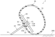
第1実施形態に係る取付ピン1は、金属製の鉄骨110(下地)にマット状の断熱材120(マット状部材)を取り付けるピンである。取付ピン1は、ピン本体10と、押さえ板20(押さえ部材)と、案内フィルム30(案内部、検査部)と、を備えている。なお、案内フィルム30は、製造時(出荷時)に、ピン本体10(又は押さえ板20)に取り付けられた構成でもよいし、施工現場において断熱材120の取付直前に、施工者(職人等)によって案内フィルム30がピン本体10(又は押さえ板20)に取り付けられる構成でもよい。
≪Mounting pin configuration≫
The
<ピン本体>
ピン本体10は、導電性材料(例えば、銅合金)で形成された細長の棒状の部材である。そして、取付時、ピン本体10が断熱材120を貫通し、先端11が鉄骨110に当接した状態でピン溶接機(図示しない)により通電することにより、先端11が鉄骨110に溶接され、ピン本体10が鉄骨110に固定されるようになっている。すなわち、詳細には、図3において、先端11は溶融した後に鉄骨110に溶接されている。ピン本体10と鉄骨110との溶接強度は、例えば、70~90kgfである。
<Pin body>
The
ピン本体10の基端12には、大径のカシメ部12a、カシメ部12bが形成されていいる。カシメ部12a、カシメ部12bは、軸方向において押さえ板20を挟持している。すなわち、押さえ板20は、ピン本体10の基端12に固定されており、ピン本体10と一体である。なお、ピン本体10の長さL10は、非圧縮時の断熱材120の厚さT120に基づいて設計されている。具体的には、長さL10は、厚さT120よりも若干短めである(L10<T120)。つまり、断熱材120は、厚さ方向において取付ピン1で若干圧縮された状態で、鉄骨110に取り付けられる(図3参照)。
A large
<押さえ板>
押さえ板20は、円板状であって、取付時に断熱材を押さえる金属製の部材である。押さえ板20の中心には、ピン本体10が挿通する挿通孔20aが形成されている。ただし、押さえ板20(押さえ部材)は円板状に限定されず、その他に例えば、四角板状、六角板状である構成でもよい。
<Press plate>
The
<案内フィルム>
案内フィルム30は、取付ピン1が落下した場合に床面200に当接することでピン本体10の先端11が下方に向くように案内する部材である(図3参照)。ここでは、案内フィルム30は、所定厚さ(例えば、0.2~0.3mm)、所定幅を有する帯状のフィルムで構成されている。
<Guidance film>
The
案内フィルム30は、樹脂製(例えば、ポリプロピレン製、ポリエステル製)であって、弾性変形可能であり、適度なばね力(復元力)を有している。このように案内フィルム30は樹脂製であるので、容易に製造可能である。案内フィルム30は、案内フィルム本体31と、一端側の一端部32と、他端側の他端部33と、を備えている。
The
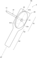
一端部32には、ピン本体10が挿通される挿通孔32aと、挿通孔32aから長手方向外側に延びるスリット32b(切れ目)とが形成されている(図2参照)。同様に、他端部33には、ピン本体10が挿通される挿通孔33aと、挿通孔33aから長手方向外側に延びるスリット33b(切れ目)とが形成されている。
The one
取付ピン1による断熱材120の取付後において、職人等が案内フィルム30を把持して引っ張ると、ピン本体10がスリット32b及び/又はスリット33b内をスライドし、案内フィルム30がピン本体10(押さえ板20)から脱離するようになっている。案内フィルム30がピン本体10から脱離する脱離強度(挿通孔32a、挿通孔33aの破断強度)は、先端11が正常に鉄骨110に溶接された場合の溶接強度(例えば、70~90kgf)よりも小さい値(例えば、2.5~3.5kgf)に設定されている。なお、この脱離強度(挿通孔32a等の破断強度)は、案内フィルム30の脱離時に職人等がバランスを失わず転倒等しないように設定されている。また、このように案内フィルム30が破断等せずにピン本体10から脱離するので、案内フィルム30を再利用(リサイクル)可能となっている。
After the
これにより、取付ピン1の取付後(溶接後)において、職人が案内フィルム30を引っ張った場合、ピン本体10が鉄骨110に固定されたまま、案内フィルム30がピン本体10から脱離したとき、ピン本体10は正常に溶接されている、と判断可能となっている。すなわち、樹脂製の案内フィルム30によって、取付ピン1が鉄骨110に正常に溶接されたか否か検査可能となっている。つまり、案内フィルム30は、取付ピン1が正常に溶接されたか否か検査する検査フィルムとしても機能している。
As a result, when a craftsman pulls the
言い換えると、案内フィルム30は、ピン本体10(押さえ板20)から延びると共に、先端11及び鉄骨110の溶接後の検査時において溶接強度よりも小さい外力でピン本体10(押さえ板20)から脱離し溶接強度を検査する検査部として機能している。
In other words, the
脱離強度は、例えば、ピン本体10に対するスリット32b等の長さ、幅、内側形状(凹凸形状)を変更することで調整可能である。
The detachment strength can be adjusted by, for example, changing the length, width, and inner shape (uneven shape) of the
案内フィルム本体31は、押さえ板20の裏面側から押さえ板20を超え表面側に向かって延びており、環状を呈している。すなわち、案内フィルム本体31は、押さえ板20から軸方向外側(図3の紙面右側)に向かって延びている。つまり、案内フィルム30は、押さえ板20を囲んでいる。
The guide film
このように、案内フィルム本体31は環状であるので、職人等は環状の案内フィルム本体31を容易に把持可能となっている。
As described above, since the guide film
案内フィルム30は、展開した状態において、概ね菱形であり、その幅W30は、長手方向における中心線O1よりも他端部33側のオフセット位置で最大となっている(図2参照)。これにより、環状の案内フィルム30の重心が他端部33側にオフセットし、案内フィルム30が他端部33側に転動し易くなっている。
The
すなわち、案内フィルム30が鉛直下向きで落下しても、床面200上を案内フィルム30が他端部33側に転動し、先端11が速やかに下方を向くようになっている。その他、案内フィルム30の幅方向における各最頂部30aから、幅方向外側に延びる舌片をそれぞれ設け、幅方向における案内フィルム30の転動をガイドするようにしてもよい。前記舌片は、断面視において円弧状であることが好ましい。また、前記舌片を中心線O1上に設けてもよい。
That is, even if the
案内フィルム30の直径D30は、押さえ板20の直径D20(例えば、30mm)よりも大きく構成されている(D30>D20)。
The diameter D30 of the
このように、案内フィルム30は環状かつ樹脂製であるので、取付現場において職人が取付ピン1を先端11が上向きで落としたとしても、案内フィルム本体31が弾性変形し、そのばね力(復元力)により跳ね返りつつ、環状の案内フィルム30が床面200に対して転動し、ピン本体10の先端11が床面200(下方)を向くように案内されるようになっている(図4参照)。
As described above, since the
案内フィルム30の色は、ピン本体10の長さL10に対応して、例えば、黄色、赤色、青色、緑色、白色に区別されている。ここで、ピン本体10の長さL10は断熱材120の厚さT120に対応しているので、取付ピン1で断熱材120を押さえた状態で、案内フィルム30の色に基づいて、断熱材120の厚さT120を把握可能となっている。
The colors of the
≪取付ピンの作用効果≫
第1実施形態に係る取付ピン1の一作用効果を説明する。
職人が取付ピン1を落としたとしても、案内フィルム30が床面200に当接し、ピン本体10の先端11が下方(床面200)に向くので安全である。すなわち、職人等が取付ピン1を踏んだとしても、職人等が足を怪我する虞はない。
≪Effects of the mounting pin≫
One function and effect of the mounting
Even if a craftsman drops the mounting
≪変形例≫
以上、本発明の一実施形態について説明したが、本発明はこれに限定されず、例えば、次のように変更してもよい。また、後記する形態に係る構成と適宜組み合わせてもよい。
≪Modification example≫
Although one embodiment of the present invention has been described above, the present invention is not limited thereto, and may be modified as follows, for example. Further, the present invention may be appropriately combined with configurations related to forms described later.
前記した実施形態では、案内部が帯状の案内フィルム30である構成を例示したが、その他に例えば、案内部が、押さえ板20から軸方向外側に向かって延び、頂角が鈍角であって外形が円錐状部材である構成としてもよい。また、案内部が、押さえ板20の外周縁から軸方向外側に延出しピン本体10を中心とする筒状部材である構成としてもよい。
In the above-described embodiment, the guide portion is a belt-shaped
前記した実施形態では、溶接強度の検査時、ピン本体10がスリット32b及びスリット33bをスライドし、案内フィルム30がピン本体10から脱離する構成を例示したが、その他に例えば、案内フィルム30が破断し、案内フィルム30がピン本体10から脱離する構成としてもよい。具体的に例えば、案内フィルム30を引っ張った場合に正常な溶接強度未満で破断するミシン線や溝線を幅方向に形成する構成としてもよい。すなわち、ミシン線や溝線が、前記正常な溶接強度よりも小さい破断強度で破断し、案内フィルム30がピン本体10から脱離する構成としてもよい。この場合において、破断強度が異なるミシン線等を案内フィルム30長手方向に複数形成し、同一の案内フィルム30で異なる溶接強度を検査可能とする構成としてもよい。その他、引っ張った場合に挿通孔32a、挿通孔33aが破断する構成としてもよい。
In the embodiment described above, the
前記した実施形態では、案内フィルム30がピン本体10に取り付けられた構成を例示したが、その他に例えば、案内フィルム30が押さえ板20に取り付けられた構成としてもよい。
In the embodiment described above, the configuration in which the
前記した実施形態では、案内部が樹脂製の案内フィルム30である構成を例示したが、その他に例えば、案内部が金属製かつ環状のリング状部材である構成としてもよい。
In the above-described embodiment, the guide portion is the
前記した実施形態では、金属製の下地が鉄骨110である構成を例示したが、その他に例えば、金属製の下地が鉄筋である構成としてもよい。
In the embodiment described above, a configuration in which the metal base is the
前記した実施形態では、マット状部材が断熱材120である構成を例示したが、その他に例えば、マット状部材が防音材等である構成としてもよい。
In the above-described embodiment, the mat-like member is the
前記した実施形態では、案内フィルム30が、(1)押さえ板20から軸方向外側に向かって延び、落下した場合に床面に当接することで先端11が下方に向くように案内する案内部としての機能と、(2)ピン本体10(押さえ板20)から延びると共に、先端11及び鉄骨110の溶接後の検査時において溶接強度よりも小さい外力でピン本体10(押さえ板20)から脱離し溶接強度を検査する検査部としての機能と、を備える構成を例示したが、その他に例えば、案内フィルム30とは別に、検査部としての機能を有する検査フィルムを別部材として備える構成としてもよい。
In the embodiment described above, the guide film 30 (1) extends from the
≪第2実施形態≫
本発明の第2実施形態について、図5~図6を参照して説明する。
≪Second embodiment≫
A second embodiment of the present invention will be described with reference to FIGS. 5 and 6.
<案内フィルムの構成>
第2実施形態に係る取付ピン2は、案内フィルム30に代えて、案内フィルム40を備えている。案内フィルム40は、案内フィルム30と同様に、絶縁性を有する樹脂製(例えば、ポリプロピレン製、ポリエステル製)である。
<Configuration of guide film>
The mounting
案内フィルム40は、細長かつ帯状の部材であって、一端側から他端側に向かって、絶縁部41と、テーパ部42と、案内フィルム本体43と、を備えている。案内フィルム40の幅方向は図6の紙面左右方向であり、案内フィルム40の長手方向は図6の紙面上下方向である。案内フィルム40の長手方向において、絶縁部41は全体の約1/4であり、案内フィルム本体43は全体の約1/2である。案内フィルム40の幅方向において、案内フィルム本体43は、絶縁部41の約1/2である。絶縁部41の中心線O2と、案内フィルム本体43の中心線O3とは、所定距離(例えば、5~15mm)でオフセットしている。
The
このように、案内フィルム40は、幅広の絶縁部41と、幅狭の案内フィルム本体43を備えるので、図6に示すように、基材(原反)である基材シートSにおいて、2つの案内フィルム40、40を、長手方向及び幅方向において反転させ対称配置したうえで、切り出すことにより、廃棄部分を少なくできる。
In this way, the
<案内フィルム-絶縁部>
絶縁部41は、取付ピン2の鉄骨110への取付時に、押さえ板20と断熱材120とを電気的に絶縁する幅広の部分である。取付ピン2の鉄骨110への取付時は、ピン本体10の先端11と鉄骨110の溶接時である。なお、ピン本体10が断熱材120を貫通し、先端11が鉄骨110に当接した状態で、ピン溶接機(図示しない)の通電部を基端12に押し当てた状態で通電させることにより、ピン本体10内を通電し、先端11が溶融し鉄骨110に溶接される。
<Guidance film - insulation part>
The insulating
絶縁部41は、押さえ板20の裏側(断熱材120側)に設けられている。すなわち、絶縁部41は、取付ピン2の鉄骨110への取付時に、押さえ板20と断熱材120との間に挟まれるように構成されている。
The insulating
絶縁部41の幅W41(例えば、32mm)は、押さえ板20の直径D20(例えば、30mm)よりも大きい(W41>D20)。絶縁部41の長さL41は、複数の挿通孔41aに対するピン本体10の挿通位置が変化しても、絶縁部41が押さえ板20の裏側に配置される長さである。すなわち、ピン本体10の軸方向視において、絶縁部41に対するピン本体10の挿通位置が変わっても、絶縁部41が押さえ板20の裏側に配置される大きさ、つまり、絶縁部41が押さえ板20と断熱材120との間に介在する大きさに設計されている。その他、絶縁部41の表面/裏面に絶縁塗料を塗布して絶縁層を形成し、絶縁性を高めてもよい。
The width W41 (for example, 32 mm) of the insulating
絶縁部41の中心線O2上には、複数(ここでは5つ)の挿通孔41aが所定間隔D1(例えば、1.5mm)を空けて形成されている。各挿通孔41aは、後記する他端側の挿通孔43aと共に、ピン本体10が挿通される孔であり、長手方向において両外側の挿通孔41a、挿通孔43aから順に使用される。
A plurality of (five in this case)
すなわち、ピン本体10の溶接強度の検査毎に、両外側の挿通孔41a、挿通孔43aから使用され、複数回(ここでは5回)にて繰り返し検査可能となっている。つまり、案内フィルム本体43を引っ張った場合において、ピン本体10が鉄骨110に溶接(固定)されたまま、挿通孔41a、挿通孔43aが破断し、案内フィルム40がピン本体10から脱離したとき、ピン本体10は所定の溶接強度以上で鉄骨110に良好に溶接されている、と判断されるようになっている。なお、挿通孔41a、挿通孔43aの破断強度(検査強度)は、所定間隔D1、所定間隔D2、案内フィルム40の厚さを変更することで、適宜に変更できる。
That is, each time the welding strength of the
これに対して、案内フィルム本体43を引っ張った場合において、挿通孔41a、挿通孔43aが破断せず、ピン本体10が鉄骨110から脱離したとき、ピン本体10は所定の溶接強度未満で溶接されていた、つまり、溶接不良であった、と判断されるようになっている。
On the other hand, when the
絶縁部41において最も一端側(図6の紙面上側)の挿通孔41aの更に一端側には、所定間隔D1を空けてスリット41bが形成されている。これにより、最も一端側の挿通孔41aも、所定の溶接強度よりも小さい外力で破断するように構成されている。
A
すなわち、絶縁部41は、ピン本体10(押さえ板20)から延びると共に、先端11及び鉄骨110の溶接後の検査時において溶接強度よりも小さい外力でピン本体10(押さえ板20)から脱離し溶接強度を検査する検査部としても機能している。
That is, the insulating
絶縁部41の一端には、所定深さ(例えば、3.0mm)の浅底のガイド溝41cが形成されている。ガイド溝41cは、幅狭の案内フィルム本体43が挿通される溝であって(図5参照)、案内フィルム本体43を幅方向においてガイドするようになっている。ガイド溝41cは、溝底に近づくにつれて溝幅が大きくなっている。すなわち、ガイド溝41cの開口幅は、案内フィルム本体43の幅よりも小さい。これにより、案内フィルム本体43をガイド溝41cに挿通した場合、ガイド溝41cの2つの開口縁41d、41dが案内フィルム本体43に係止し、案内フィルム本体43がガイド溝41cの外側に脱落しないようになっている。
A
これにより、案内フィルム本体43の他端部がピン本体10(挿通孔43a)を中心として回動せず、案内フィルム40が環状で保持されるようになっている。すなわち、絶縁部41の中心線O2と、案内フィルム本体43の中心線O3とが、幅方向においてオフセットしているが、案内フィルム本体43がガイド溝41cに挿通されることにより、案内フィルム40が若干ねじれた状態でありながらも、環状で保持されるようになっている。
As a result, the other end of the
<案内フィルム-テーパ部>
テーパ部42は、絶縁部41と案内フィルム本体43との間に形成され、絶縁部41から案内フィルム本体43に向かうにつれて、徐々に幅狭となるテーパ部分である。すなわち、案内フィルム40の幅方向における断面積は、テーパ部42において、絶縁部41から案内フィルム本体43に向かうにつれて、徐々に小さくなっている。
<Guide film - taper part>
The
ここで、ピン本体10の溶接強度の検査時、案内フィルム本体43を把持して引っ張ると、案内フィルム40内に一端側の挿通孔41aと他端側の挿通孔43aとを支点として概ね長手方向に引張応力が発生する。このように、長手方向に引張応力が発生するが、テーパ部42において幅方向における断面積が徐々に変化しているので、挿通孔41a又は挿通孔43aが破断する前(溶接強度の検査前)に、案内フィルム40がその中間等から破断せず、溶接強度の検査不能を回避しつつ、案内フィルム40を繰り返し使用可能となっている。
Here, when inspecting the welding strength of the
これに対して、テーパ部42を備えない場合、絶縁部41と案内フィルム本体43との境界で、幅方向における断面積が急激に変化する。これにより、案内フィルム40を引っ張った際、この境界部分にクラックが発生し、案内フィルム40が破断し易くなり、溶接強度を検査不能となるうえ、案内フィルム40を繰り返し使用し難くなる。
On the other hand, when the
<案内フィルム-案内フィルム本体>
案内フィルム本体43は、細長かつ帯状の部分である。案内フィルム本体43の他端側の中心線O3上には、複数(ここでは5つ)の挿通孔43aが所定間隔D2(例えば、1.0mm)を隔てて形成されている。各挿通孔43aは、一端側の挿通孔41aと共に、ピン本体10が挿通される孔である。
<Guidance film - Guide film body>
The guide film
他端側の所定間隔D2は一端側の所定間隔D1よりも小さい(D1>D2)。これにより、溶接強度の検査時、他端側(案内フィルム本体43側)の挿通孔43a、一端側(絶縁部41側)の挿通孔41aの順で破断するように設計されている。つまり、案内フィルム40の一端側と他端側とで、検査強度が異なる構成としてもよい。その他、挿通孔41a、挿通孔43aの近傍に、検査強度(溶接強度)を記載し検査強度を明確に構成としてもよい。
The predetermined interval D2 on the other end side is smaller than the predetermined interval D1 on the one end side (D1>D2). Thereby, when testing the welding strength, it is designed to break in the order of the
<案内フィルムの作用効果>
1つの案内フィルム40に複数の挿通孔41a及び複数の挿通孔43aが形成されているので、1つの案内フィルム40を複数回繰り返し使用し、溶接強度を複数回にて検査できる。
<Effects of guide film>
Since the plurality of
押さえ板20の裏側に絶縁部41を備えるので、ピン本体10の溶接時に、押さえ板20と断熱材120との間で通電し難くなり、漏れ電流が発生し難くなる。これにより、ピン本体10の先端11と鉄骨110とを確実に溶接できる。
Since the insulating
≪変形例≫
前記した実施形態では、絶縁部41が溶接強度を検査する検査部としても機能する構成を例示したが、その他に例えば、絶縁部41とは別に、溶接強度を検査する検査片(検査部)を別部材として備える構成としてもよい。また、検査片(検査部)は、押さえ板20(押さえ部)から延びる構成としてもよい。
≪Modification example≫
In the above-described embodiment, the insulating
≪第3実施形態≫
本発明の第3実施形態について、図7を参照して説明する。
≪Third embodiment≫
A third embodiment of the present invention will be described with reference to FIG.
第3実施形態に係る案内フィルム50は、第2実施形態に係る案内フィルム40と同様に、絶縁部51と、テーパ部52と、案内フィルム本体53と、を備えている。ここで、絶縁部51の中心線O4と、案内フィルム本体53の中心線O5とは、幅方向において一致している。
The
これにより、案内フィルム50を環状にしても、幅方向において捻じれることはない。したがって、第2実施形態に係るガイド溝41c(図5、図6参照)は不要となる。なお、絶縁部51の中心線O4上には、複数の挿通孔51aとスリット51bとが形成されている。案内フィルム本体53の他端部の中心線O5上には、複数の挿通孔53aが形成されている。
Thereby, even if the
≪第4実施形態≫
本発明の第4実施形態について、図8を参照して説明する。
≪Fourth embodiment≫
A fourth embodiment of the present invention will be described with reference to FIG. 8.
第4実施形態に係る取付ピン5は、案内フィルム30に代えて、検査フィルム60(検査部)を備えている。検査フィルム60は、幅広の絶縁部61と、テーパ部62と、細長の把持部64と、を備えている。絶縁部61は、ピン本体10の溶接時、押さえ板20と断熱材120とを電気的に絶縁する部分である。
The mounting
絶縁部61の中心線O6上には複数の挿通孔61aとスリット61bとが形成されている。把持部64は、溶接強度の検査時に職人等が把持して引っ張る部分である。絶縁部61の中心線O6と、把持部64の中心線O7とは、幅方向において、一致している。
A plurality of
また、把持部64を階段状に折り返して弾性を付与し、この弾性を有するばね状の把持部64が、取付ピン5の落下時に、ピン本体10の先端11を下方に案内するように構成してもよい。
Further, the gripping
1 取付ピン
10 ピン本体
11 先端
12 基端
20 押さえ板(押さえ部材)
30 案内フィルム(案内部、検査部)
31 案内フィルム本体
32 一端部
33 他端部
40 案内フィルム
41 絶縁部(検査部)
41a 挿通孔
42 テーパ部
43 案内フィルム本体
43a 挿通孔
110 鉄骨(下地)
120 断熱材(マット状部材)
200 床面
1 Mounting
30 Guide film (guidance department, inspection department)
31 Guide film
120 Insulating material (mat-like member)
200 Floor surface
Claims (2)
導電性材料から形成され、取付時に前記マット状部材を貫通すると共に先端が前記下地に溶接されるピン本体と、
前記ピン本体の基端に固定されると共に、前記マット状部材を押さえる押さえ部材と、
前記ピン本体が挿通される挿通孔が形成され、検査前に前記ピン本体から延びると共に、前記先端及び前記下地の溶接後の検査時において溶接強度よりも小さい外力で前記ピン本体から脱離し溶接強度を検査する検査部と、
を備える
ことを特徴とする取付ピン。 A mounting pin for attaching a mat-like mat member to a metal base,
a pin body made of a conductive material, which penetrates the mat-like member when attached and whose tip is welded to the base;
a pressing member fixed to the base end of the pin body and pressing the mat-like member;
An insertion hole is formed through which the pin body is inserted, and extends from the pin body before inspection, and is inserted from the pin body with an external force smaller than the welding strength during an inspection after welding the tip and the base. an inspection section for inspecting detachment and welding strength;
A mounting pin characterized by comprising:
ことを特徴とする請求項1に記載の取付ピン。 The inspection part is strip-shaped and has a plurality of insertion holes formed in the longitudinal direction, and when the insertion holes are broken by an external force smaller than the welding strength during the inspection , the inspection part is detached from the pin body and welded multiple times. The mounting pin according to claim 1, wherein the mounting pin can be inspected for strength.
Applications Claiming Priority (3)
| Application Number | Priority Date | Filing Date | Title |
|---|---|---|---|
| JP2022096339 | 2022-06-15 | ||
| JP2022096339 | 2022-06-15 | ||
| JP2023063767A JP7336107B1 (en) | 2022-06-15 | 2023-04-10 | mounting pin |
Related Parent Applications (1)
| Application Number | Title | Priority Date | Filing Date |
|---|---|---|---|
| JP2023063767A Division JP7336107B1 (en) | 2022-06-15 | 2023-04-10 | mounting pin |
Publications (2)
| Publication Number | Publication Date |
|---|---|
| JP7370552B1 true JP7370552B1 (en) | 2023-10-30 |
| JP2023183410A JP2023183410A (en) | 2023-12-27 |
Family
ID=87764104
Family Applications (2)
| Application Number | Title | Priority Date | Filing Date |
|---|---|---|---|
| JP2023063767A Active JP7336107B1 (en) | 2022-06-15 | 2023-04-10 | mounting pin |
| JP2023111078A Active JP7370552B1 (en) | 2022-06-15 | 2023-07-05 | mounting pin |
Family Applications Before (1)
| Application Number | Title | Priority Date | Filing Date |
|---|---|---|---|
| JP2023063767A Active JP7336107B1 (en) | 2022-06-15 | 2023-04-10 | mounting pin |
Country Status (1)
| Country | Link |
|---|---|
| JP (2) | JP7336107B1 (en) |
Citations (4)
| Publication number | Priority date | Publication date | Assignee | Title |
|---|---|---|---|---|
| JP2004082127A (en) | 2002-07-01 | 2004-03-18 | Shinjo Mfg Co Ltd | Welding pin for mounting heat insulating material |
| JP2006167739A (en) | 2004-12-14 | 2006-06-29 | Nippon Stud Welding Co Ltd | Stud, and tool for applying torque to the stud |
| JP2016211630A (en) | 2015-05-01 | 2016-12-15 | 片山ストラテック株式会社 | Torshear type stud bolt |
| JP2017127902A (en) | 2016-01-20 | 2017-07-27 | 一文機工株式会社 | Stud pin |
Family Cites Families (4)
| Publication number | Priority date | Publication date | Assignee | Title |
|---|---|---|---|---|
| JPS4937036U (en) * | 1972-06-30 | 1974-04-02 | ||
| JPH0738730Y2 (en) * | 1991-08-28 | 1995-09-06 | 佐々木金属工業株式会社 | Stud pin |
| JPH10245904A (en) * | 1997-03-04 | 1998-09-14 | Shin Nippon Kogyo Kk | Pin for fixing covering material |
| JP2010076406A (en) * | 2008-09-24 | 2010-04-08 | Hajime Saito | Boat type pin |
-
2023
- 2023-04-10 JP JP2023063767A patent/JP7336107B1/en active Active
- 2023-07-05 JP JP2023111078A patent/JP7370552B1/en active Active
Patent Citations (4)
| Publication number | Priority date | Publication date | Assignee | Title |
|---|---|---|---|---|
| JP2004082127A (en) | 2002-07-01 | 2004-03-18 | Shinjo Mfg Co Ltd | Welding pin for mounting heat insulating material |
| JP2006167739A (en) | 2004-12-14 | 2006-06-29 | Nippon Stud Welding Co Ltd | Stud, and tool for applying torque to the stud |
| JP2016211630A (en) | 2015-05-01 | 2016-12-15 | 片山ストラテック株式会社 | Torshear type stud bolt |
| JP2017127902A (en) | 2016-01-20 | 2017-07-27 | 一文機工株式会社 | Stud pin |
Also Published As
| Publication number | Publication date |
|---|---|
| JP7336107B1 (en) | 2023-08-31 |
| JP2023183376A (en) | 2023-12-27 |
| JP2023183410A (en) | 2023-12-27 |
Similar Documents
| Publication | Publication Date | Title |
|---|---|---|
| US8921696B2 (en) | Wiring harness and a method for producing the same, and a method for connecting insulated wires | |
| US6393924B1 (en) | Testing method for non-destructive testing of a welded connector, a testing device and an ultrasonic welding apparatus having such a device | |
| EP3868509B1 (en) | Laser welding method and laser welding monitoring system for a secondary battery | |
| Xing et al. | Mechanical properties of self-piercing riveted joints in aluminum alloy 5052 | |
| JP2002536190A (en) | Method and apparatus for crimping and securing a composite electrical insulator | |
| JP7121911B2 (en) | WELDING QUALITY INSPECTION METHOD AND WELDING QUALITY INSPECTION DEVICE | |
| JP6901047B2 (en) | Wire connection structure and wire connection method | |
| JP2023183410A (en) | mounting pin | |
| US9279755B2 (en) | Testing methods and pass/fail criteria for electric joints | |
| US8336351B2 (en) | Apparatus and methods that apply a press force including a separately applied core crimp force | |
| EP3540408A1 (en) | Method of manufacturing ctod test piece, and plastic strain adjusting jig | |
| JP4064828B2 (en) | Evaluation method of weld zone | |
| JP2010019660A (en) | Test piece for shearing fatigue test | |
| JP5001049B2 (en) | Spot welding strength evaluation method and apparatus | |
| JP2007103337A (en) | Fuel cell stack | |
| JP2010232119A (en) | Crimping terminal and its winding state inspection method | |
| KR102179272B1 (en) | Method for checking the welding state and apparatus for the same | |
| RU2458332C1 (en) | Offscouring test method of weld joint of polymer tube with electric coupling | |
| CN115575317A (en) | Solder joint quality inspection standard determination method and solder joint quality inspection system | |
| JP2006030123A (en) | Tension testing method and holding tool for tension test | |
| JP2006344540A (en) | Terminal crimping device | |
| CN212008167U (en) | Test tool for shear strength of titanium alloy rivet | |
| Huang et al. | Mechanical behaviors of self-piercing riveting joining dissimilar sheets | |
| WO2019181633A1 (en) | Connection structure of electric wires, and method for producing harness | |
| JP2020184485A (en) | Inspection method for electric wires with terminals and electric wires with terminals |
Legal Events
| Date | Code | Title | Description |
|---|---|---|---|
| A621 | Written request for application examination |
Free format text: JAPANESE INTERMEDIATE CODE: A621 Effective date: 20230705 |
|
| A871 | Explanation of circumstances concerning accelerated examination |
Free format text: JAPANESE INTERMEDIATE CODE: A871 Effective date: 20230705 |
|
| A131 | Notification of reasons for refusal |
Free format text: JAPANESE INTERMEDIATE CODE: A131 Effective date: 20230808 |
|
| A521 | Request for written amendment filed |
Free format text: JAPANESE INTERMEDIATE CODE: A523 Effective date: 20230908 |
|
| TRDD | Decision of grant or rejection written | ||
| A01 | Written decision to grant a patent or to grant a registration (utility model) |
Free format text: JAPANESE INTERMEDIATE CODE: A01 Effective date: 20230926 |
|
| A61 | First payment of annual fees (during grant procedure) |
Free format text: JAPANESE INTERMEDIATE CODE: A61 Effective date: 20231010 |
|
| R150 | Certificate of patent or registration of utility model |
Ref document number: 7370552 Country of ref document: JP Free format text: JAPANESE INTERMEDIATE CODE: R150 |