JP2017127902A - Stud pin - Google Patents
Stud pin Download PDFInfo
- Publication number
- JP2017127902A JP2017127902A JP2016021278A JP2016021278A JP2017127902A JP 2017127902 A JP2017127902 A JP 2017127902A JP 2016021278 A JP2016021278 A JP 2016021278A JP 2016021278 A JP2016021278 A JP 2016021278A JP 2017127902 A JP2017127902 A JP 2017127902A
- Authority
- JP
- Japan
- Prior art keywords
- pin
- stud pin
- tip
- stud
- shaft pin
- Prior art date
- Legal status (The legal status is an assumption and is not a legal conclusion. Google has not performed a legal analysis and makes no representation as to the accuracy of the status listed.)
- Pending
Links
- 239000000463 material Substances 0.000 claims abstract description 49
- 239000004020 conductor Substances 0.000 claims abstract description 5
- 238000003466 welding Methods 0.000 abstract description 31
- 239000010953 base metal Substances 0.000 description 9
- 238000002844 melting Methods 0.000 description 7
- 230000008018 melting Effects 0.000 description 7
- 238000009423 ventilation Methods 0.000 description 7
- 238000000034 method Methods 0.000 description 5
- 229910000831 Steel Inorganic materials 0.000 description 3
- 239000011248 coating agent Substances 0.000 description 3
- 238000000576 coating method Methods 0.000 description 3
- 230000005611 electricity Effects 0.000 description 3
- 239000011810 insulating material Substances 0.000 description 3
- 239000010959 steel Substances 0.000 description 3
- XEEYBQQBJWHFJM-UHFFFAOYSA-N Iron Chemical compound [Fe] XEEYBQQBJWHFJM-UHFFFAOYSA-N 0.000 description 2
- 238000010411 cooking Methods 0.000 description 2
- 230000007547 defect Effects 0.000 description 2
- 229910001369 Brass Inorganic materials 0.000 description 1
- 239000010951 brass Substances 0.000 description 1
- 238000010586 diagram Methods 0.000 description 1
- 230000004927 fusion Effects 0.000 description 1
- 239000011491 glass wool Substances 0.000 description 1
- 229910052742 iron Inorganic materials 0.000 description 1
- 239000000155 melt Substances 0.000 description 1
- 239000002184 metal Substances 0.000 description 1
- 229910052751 metal Inorganic materials 0.000 description 1
- 239000011490 mineral wool Substances 0.000 description 1
- 238000000465 moulding Methods 0.000 description 1
- 238000009987 spinning Methods 0.000 description 1
Images


Landscapes
- Building Environments (AREA)
- Arc Welding Control (AREA)
Abstract
Description
本発明は、建物の鉄骨や機械設備等の母材面にグラスウール、ロックウール等からなる断熱材や防音材等の被覆材で覆った後、該被覆材を固定する際に使用されるスタッドピンに関するものである。 The present invention relates to a stud pin used when fixing a covering material after covering the base material surface of a building steel frame or mechanical equipment with a covering material such as a heat insulating material or a soundproof material made of glass wool, rock wool or the like. It is about.
従来、スタッドピンには、建物の鉄骨や機械設備等の母材面に、予め先行してスタッドピンを溶接しておき、その上から断熱材や防音材等の被覆材を巻き付けて該被覆材を固定する手順の、所謂、先打ち用のスタドピンがある。
一方、その逆として、建物の鉄骨や機械設備等の母材面に断熱材等の被覆材を先に巻き付けておき、その上からスタッドピンを差し込んで母材面に溶接して被覆材を固定する手順の、所謂、後打ち用のスタッドピンがある。
本発明は、後者の後打ち用のスタッドピンに関するものであるが、この後打ち用のスタッドピンには、これまで各種の形状等いろいろ工夫されたものが提案されている。Conventionally, a stud pin is previously welded in advance to a base metal surface of a building steel frame or mechanical equipment, and a covering material such as a heat insulating material or a soundproof material is wound around the stud pin. There is a so-called pre-stud stud pin for the procedure of fixing the screw.
On the other hand, the covering material such as a heat insulating material is wound around the base material surface of the building steel frame or mechanical equipment first, and then the stud pin is inserted from above and welded to the base material surface to fix the covering material. There is a so-called post-placed stud pin for the procedure to be performed.
The present invention relates to the latter stud pin for post-striking, and various devices such as various shapes have been proposed so far for this post-spinning stud pin.
ところで、近年、特に天井裏等に配設される通風ダクトの場合、作業性やコスト面からダクトの機能が保持される範囲で、厚さの薄い母材からなる軽量な通風ダクトが採用される傾向にある。その結果、スタッド溶接に際し厚さの薄い母材では溶接熱に耐えきれず、所謂、「穴あき」と言われる溶接不良の問題が生じてきている。 By the way, in recent years, especially in the case of a ventilation duct disposed on the ceiling or the like, a lightweight ventilation duct made of a thin base material is employed as long as the function of the duct is maintained in terms of workability and cost. There is a tendency. As a result, a thin base metal cannot withstand the welding heat during stud welding, and a so-called “perforated” problem of poor welding has arisen.
特に問題となるのは、上述した先打ち用のスタッドピンの場合は、作業者がその場で溶接状態の良否を肉眼目視で確認でき、溶接不良と分かればその場で打ち直しということもできる。しかし、後打ち用のスタッドピンの場合は、溶接部分が被覆材で覆われており溶接状態を肉眼目視で確認することは不可能で、穴あき等の溶接不良を見落とされる可能性が心配である。そこで、厚さの薄い母材にも安心して使用できる後打ち用のスタッドピンが望まれている。 In particular, in the case of the above-described stud pin for leading, the operator can visually check the quality of the welded state on the spot, and if it is known that the welding is poor, it can be said that the hammer is reworked on the spot. However, in the case of a post-stud stud pin, the welded part is covered with a covering material, so it is impossible to visually check the welded state, and there is a concern that welding defects such as holes may be overlooked. is there. Therefore, there is a demand for a stud pin for post-coating that can be used with peace of mind even for a thin base material.
上記、課題を解決するため、本発明者等は鋭意研究の結果、次のような構成を採用した。すなわち、本発明に係る後打ち用のスタッドピンは、導電性の材質からそれぞれ構成された、軸ピンの後端には盤状の座金が固定され、軸ピンの先端は先鋭な先端部とその直傍に軸ピン径より大きな球面体部の鍔を形成することにより、厚さの薄い母材にも十分に対応できる後打ち用のスタッドピンを開発した。 In order to solve the above problems, the present inventors have adopted the following configuration as a result of intensive research. That is, the stud pin for post-cooking according to the present invention is composed of a conductive material, and a disc-shaped washer is fixed to the rear end of the shaft pin, and the tip of the shaft pin has a sharp tip and its tip. We have developed a stud pin for post-coiling that can sufficiently handle even a thin base metal by forming a heel of a spherical body part larger than the diameter of the shaft pin in the immediate vicinity.
その大きな特徴として、軸ピンの先端には先鋭な先端部と、その直傍に形成する球面体部の鍔が母材に対して凸状湾曲面を形成してなることにある。さらに詳しくは、φ1.3〜1.8mmの軸ピンにあっては、該軸ピン先端の直傍にR3.0〜4.0の凸状湾曲面からなる球面体部の鍔を形成してなることにある。この要件を満たすことにより0.4mmという厚さの薄い母材に対してスタッド溶接を可能にする。 The major feature is that the tip of the shaft pin has a sharp tip and a ridge of a spherical body portion formed in the immediate vicinity thereof to form a convex curved surface with respect to the base material. More specifically, in the case of a shaft pin of φ1.3 to 1.8 mm, a ridge of a spherical body part made of a convex curved surface of R3.0 to 4.0 is formed immediately adjacent to the tip of the shaft pin. To be. By satisfying this requirement, stud welding is possible for a thin base metal having a thickness of 0.4 mm.
ここでいう鍔の球面体部とは、鍔全体が球体で形成されていても良く、少なくとも球面体部の湾曲面が母材に向けて凸状湾曲面に形成されていれば、四半球体や半球体等で形成される球面体部であっても良く、全球円の球体部に拘束されるものでない。 As used herein, the spherical surface portion of the heel may be formed of a sphere as a whole, and if at least the curved surface of the spherical body portion is formed into a convex curved surface toward the base material, It may be a spherical body part formed of a hemisphere or the like, and is not restricted by a spherical part of a full circle.
要するに、従来のスタッドピン溶接の考え方として、スタッドピンの先端を鋭く先細り形状に維持して母材面との接点を小さくさ保ったうえで、高圧電流を急激に流して、ピン先端に強力なスパークを発生させて瞬間的な高い溶融温度から溶け出す溶融金属量でもって強靭な溶着力を求めてきた。しかし、前述した通風ダクトのような肉厚の薄い材料を採用して軽量化を求めた母材に対しては、従来のスタッドピンでは母材面に与えるダメージが大きすぎて「穴あき」という溶接不良の限界を見た。 In short, the conventional idea of stud pin welding is to maintain the tip of the stud pin in a sharply tapered shape and keep the contact point with the base metal surface small, and then rapidly apply a high-voltage current to We have been seeking strong welding power with the amount of molten metal that is generated from sparks and melted from an instantaneous high melting temperature. However, for a base material that has been sought to reduce weight by adopting a thin material such as the ventilation duct described above, the damage to the base material surface is too great for a conventional stud pin, and it is called `` perforated '' I saw the limit of poor welding.
そこで、本発明者等は、逆の発想から母材面へのダメージを如何に少なくするかを念頭に研究した結果、本来のサイリスター(SCR)の放電方法では電流のコントロールが制御不可である。そこで、ピンの材質や形状によって流れる電流の量および速度を示す電流波形のパターンに着目して、この電流波形の変化から導かれる要件をピン形状に結び付ける工夫をした。
本発明はピン先に示す電流波形から、高温均等な溶融温度と溶融速度から溶融積量と広い溶着面積のバランスを追究して、これを溶接電流の放電特性に照らして母材に適応する条件を算出することにより、以下の構成による後打ち用のスタッドピンの完成に到達した。
即ち、本発明である後打ち用のスタッドピンとは、導電性の材質からそれぞれ構成された、軸ピンの後端には盤状の座金が固定され、軸ピンの先端は先鋭な先端部とその直傍に軸ピン径より大きな球面体部の鍔を形成することを特徴とする。Therefore, as a result of studying how to reduce the damage to the base metal surface from the reverse idea, the present inventors cannot control the current with the original thyristor (SCR) discharge method. Therefore, paying attention to the current waveform pattern indicating the amount and speed of the current that flows depending on the material and shape of the pin, we devised to tie the requirements derived from this change in the current waveform to the pin shape.
In the present invention, the current waveform shown at the pin tip is used to investigate the balance between the melt volume and the wide welding area from the uniform melting temperature and melting speed at high temperatures, and this is applied to the base metal in light of the discharge characteristics of the welding current. As a result, the completion of the stud pin for post-coating with the following configuration was reached.
In other words, the post-stud stud pin according to the present invention is made of a conductive material, and a disc-shaped washer is fixed to the rear end of the shaft pin, and the tip of the shaft pin has a sharp tip and its tip. A ridge of a spherical body part larger than the shaft pin diameter is formed in the immediate vicinity.
本発明に係る後打ち用のスタッドピンは、母材面に対する適切な条件で軸ピンの先端部を均等な溶融温度と溶融速度で溶融させると供に同時に該先端部の直傍に形成される軸ピン径より大きくした球面体部の鍔の凸状湾曲部にも同様に均等な溶融温度と溶融速度および溶融積量を、溶接電流の放電特性に照らして算出することの結果、これらの制御を本発明品のピン形状により求めることができた。
即ち、母材面へのダメージのない条件をピンの形状から設定することで、軸ピンの先端部とその直傍の鍔の球面体部の溶融積量で、より広い溶着面でもって溶接させることで、肉厚の薄い母材が用いられていても穴あき不良が回避された。特に、本発明品は市販のスタッドピンでは不可能とされる0.4mm厚の薄い母材に対しても、穴あきの不良溶接も発生させず、後打ち用としても安心して使用できるスタッドピンが提供できた。The stud pin for post-cooking according to the present invention is formed immediately adjacent to the tip portion at the same time when the tip portion of the shaft pin is melted at an equal melting temperature and melting speed under appropriate conditions with respect to the base material surface. As a result of calculating the uniform melting temperature, melting rate and melt volume in the same way for the convex curved part of the spherical body part larger than the shaft pin diameter in light of the discharge characteristics of the welding current, these controls Can be obtained from the pin shape of the product of the present invention.
That is, by setting the conditions that do not cause damage to the base metal surface from the shape of the pin, welding is performed with a wider welding surface with the molten product amount of the tip of the shaft pin and the spherical body portion of the immediately adjacent flange. Thus, even when a thin base material was used, a perforation defect was avoided. In particular, the product of the present invention has a stud pin that can be used with confidence even for post-working without causing poor welding with a hole even for a thin base metal with a thickness of 0.4 mm, which is impossible with a commercially available stud pin. I was able to provide it.
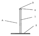
以下、図1ないし図4を参照しつつ、本発明に係る後打ち用のスタッドピンの一実施例を説明すると、図において、Aは導電性の材質からそれぞれ構成されてなる本発明の後打ち用のスタッドピンである。そして、Bは0.4mm厚の亜鉛メッキ製の鉄板で成型加工された通風ダクト(母材)である。
さらに詳細には、図中1は真鍮材からなる長さが50mmでφ1.6mmの軸ピンである。2は軸ピン1の後端にカシメ等により固定されたφ25mmの盤状の座金である。3は軸ピン1の先端に形成された先鋭な円錐形の高さ0.6mmの先端部であって、4はその先端部3の直傍に形成された球面体部の鍔である。そして、この鍔4の球面体部は母材Bに対しR3.2mmの凸状湾曲面を形成してなる。
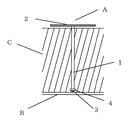
図2は、スタッドピンAが被覆材Cを貫通して、その先端部が母材Bに接した状態の通電前の概念説明図である。そして、次の図3は、同様にスタッドピンAが被覆材Cを貫通して、その先端部が母材Bに接した状態において、通電して溶接した後の概念説明図である。この図からも明らかなように本発明によるスタッドピンAと母材Bとは広い溶着面積4’●で溶接されおり、従来のストレートなスタッドピンの場合による母材Bとの溶着面積1’○との差が理解できる。Hereinafter, an embodiment of a stud pin for post-scoring according to the present invention will be described with reference to FIGS. 1 to 4. In the figure, A represents the post-striking of the present invention formed of a conductive material. It is a stud pin for. B is a ventilation duct (base material) molded by a galvanized iron plate having a thickness of 0.4 mm.
More specifically,
FIG. 2 is a conceptual explanatory diagram before energization in a state in which the stud pin A penetrates the covering material C and the tip portion thereof is in contact with the base material B. Next, FIG. 3 is a conceptual explanatory view after the energization and welding in the state where the stud pin A penetrates the covering material C and the tip thereof is in contact with the base material B. As is apparent from this figure, the stud pin A and the base material B according to the present invention are welded with a wide welding area 4 '●, and the welding area 1' ○ with the base material B in the case of a conventional straight stud pin is welded. You can understand the difference.
図4の部分拡大図において示すように、スタッドピンAにあってはφ1.6mm軸ピン1に対し鍔4の凸状湾曲面の断面形状R値の曲線が破線40の凸状湾曲面線40として示され、破線40’のように、従来のスタッドピンの成型加工に際して発生することのある単純傾斜線40’とは異なる。 As shown in the partially enlarged view of FIG. 4, in the stud pin A, the convex
本発明よるスタッドピンAの溶接手順は、母材Bの外壁に外張りされた被覆材Cの適切な個所にスタッドピンAを差し込んで、軸ピン1の先端部3を母材Bに接触させる。次いで、溶接機本体を操作して溶接ガンを介して座金2より溶接電流を流して通常のスタッド溶接を実施する。 In the welding procedure of the stud pin A according to the present invention, the stud pin A is inserted into an appropriate portion of the covering material C that is externally attached to the outer wall of the base material B, and the
上記、実施するための形態として、0.4mm厚の母材Bを用いた通風ダクトにおいて被覆材Cを外張りし、その被覆材Cを通風ダクトに固定する場合についてスタッドピンAの使用例を示したが、本発明のスタッドピンAは、通風ダクトの用途のみに限定されるものではなく、通常のスタッド溶接分野においても使用できるものである。また、0.4mm厚の母材Bに対しての特性を示したが、これよりも厚い母材に対しても、より安定した溶接が可能なことは言及するまでもない。そして、スタッドピンAの座金を消去することで、先打ち用のスタッドピンとして使用可能なことも言及するまでもない。
更には、スタッドピンA、母材Bそして被覆材Cの強度や重量等に制限や条件を付することで、材質に流れる溶接電流の放電特性に照らしての算出から多様な構成によるスタッドピンが提供できる。As an embodiment for carrying out the above, an example of using the stud pin A in the case where the covering material C is externally attached in the ventilation duct using the base material B having a thickness of 0.4 mm and the covering material C is fixed to the ventilation duct. Although shown, the stud pin A of the present invention is not limited to the use of a ventilation duct, and can be used in the field of ordinary stud welding. Moreover, although the characteristic with respect to the base material B of 0.4 mm thickness was shown, it cannot be overemphasized that the more stable welding is possible also to the base material thicker than this. Then, it goes without saying that it is possible to use the stud pin A as a leading stud pin by erasing the washer of the stud pin A.
Furthermore, by applying restrictions and conditions to the strength and weight of the stud pin A, the base material B, and the covering material C, stud pins with various configurations can be obtained from calculations in light of the discharge characteristics of the welding current flowing through the material. Can be provided.
A・・・本発明のスタッドピン
B・・・母材
C・・・被覆材
1・・・軸ピン
1’・・・軸ピン溶接面積
2・・・座金
3・・・先端部
4・・・球面体部
4’・・・球面体部溶接面積
40・・・凸状湾曲面線
40’・・・単純傾斜線A ... Stud pin B of the present invention ... Base material C ... Covering
Claims (3)
Priority Applications (1)
| Application Number | Priority Date | Filing Date | Title |
|---|---|---|---|
| JP2016021278A JP2017127902A (en) | 2016-01-20 | 2016-01-20 | Stud pin |
Applications Claiming Priority (1)
| Application Number | Priority Date | Filing Date | Title |
|---|---|---|---|
| JP2016021278A JP2017127902A (en) | 2016-01-20 | 2016-01-20 | Stud pin |
Publications (1)
| Publication Number | Publication Date |
|---|---|
| JP2017127902A true JP2017127902A (en) | 2017-07-27 |
Family
ID=59394294
Family Applications (1)
| Application Number | Title | Priority Date | Filing Date |
|---|---|---|---|
| JP2016021278A Pending JP2017127902A (en) | 2016-01-20 | 2016-01-20 | Stud pin |
Country Status (1)
| Country | Link |
|---|---|
| JP (1) | JP2017127902A (en) |
Cited By (2)
| Publication number | Priority date | Publication date | Assignee | Title |
|---|---|---|---|---|
| JP2020093275A (en) * | 2018-12-11 | 2020-06-18 | 日鉄日新製鋼株式会社 | Energizing jig for stud welding and stud welding method |
| JP7336107B1 (en) | 2022-06-15 | 2023-08-31 | 株式会社スローテック | mounting pin |
-
2016
- 2016-01-20 JP JP2016021278A patent/JP2017127902A/en active Pending
Cited By (6)
| Publication number | Priority date | Publication date | Assignee | Title |
|---|---|---|---|---|
| JP2020093275A (en) * | 2018-12-11 | 2020-06-18 | 日鉄日新製鋼株式会社 | Energizing jig for stud welding and stud welding method |
| JP7172539B2 (en) | 2018-12-11 | 2022-11-16 | 日本製鉄株式会社 | Energizing jig for stud welding and stud welding method |
| JP7336107B1 (en) | 2022-06-15 | 2023-08-31 | 株式会社スローテック | mounting pin |
| JP7370552B1 (en) | 2022-06-15 | 2023-10-30 | 株式会社スローテック | mounting pin |
| JP2023183376A (en) * | 2022-06-15 | 2023-12-27 | 株式会社スローテック | mounting pin |
| JP2023183410A (en) * | 2022-06-15 | 2023-12-27 | 株式会社スローテック | mounting pin |
Similar Documents
| Publication | Publication Date | Title |
|---|---|---|
| US11701733B2 (en) | High performance contact tip and nozzle assembly for an arc welding apparatus | |
| JP2007000933A (en) | TIG or braze welding using metal transfer through a liquid bridge | |
| DE212013000247U1 (en) | System for starting and using a combined cored wire feed and high intensity power source for welding | |
| EP2213402A1 (en) | TIG welding torch, electrode unit for and method for operating the Torch | |
| US8776369B2 (en) | Through-hole manufacturing method for cylindrical body wall and cylindrical body structure | |
| KR101764032B1 (en) | Torch for welding | |
| JP2013252523A (en) | Two-electrode type hot wire mag welding method | |
| Spiridonova et al. | The use of composite coatings during metallurgical equipment parts repair | |
| KR101846814B1 (en) | welding tip | |
| US3053966A (en) | Metal cutting by means of electric arc | |
| JPS63295068A (en) | Bar-shaped electrodeposited stud | |
| JP6242836B2 (en) | Stud welding method | |
| CN103920971A (en) | Welding method, comb plate and welding rod used in process of storage battery production | |
| JPH11291065A (en) | Friction joining method | |
| JP2000246450A (en) | Plasma arc overlay welding of extremely low melting point metal | |
| US10955133B2 (en) | Method for flame straightening and burner assembly for this purpose | |
| KR20090030606A (en) | Submerged Arc Welding Wire | |
| JPH1110338A (en) | Welding apparatus and its control method | |
| RU167600U1 (en) | Spiral welding electrode | |
| JP3112900B2 (en) | Stud welding pin | |
| JPS63171273A (en) | Method for attaching ceramics piece | |
| US2403438A (en) | Welding method | |
| KR101482228B1 (en) | Welding tip, jig for tip coaing, and method for coating a tip | |
| CN114682877A (en) | Baffle plate structure suitable for welding thin-wall component and welding method thereof | |
| KR200333342Y1 (en) | Bended arc electrode |