JP7561551B2 - Motor - Google Patents

Motor Download PDF

Info

Publication number
JP7561551B2
JP7561551B2 JP2020152985A JP2020152985A JP7561551B2 JP 7561551 B2 JP7561551 B2 JP 7561551B2 JP 2020152985 A JP2020152985 A JP 2020152985A JP 2020152985 A JP2020152985 A JP 2020152985A JP 7561551 B2 JP7561551 B2 JP 7561551B2
Authority
JP
Japan
Prior art keywords
recess
insulator
terminal
conductor
conductive
Prior art date
Legal status (The legal status is an assumption and is not a legal conclusion. Google has not performed a legal analysis and makes no representation as to the accuracy of the status listed.)
Active
Application number
JP2020152985A
Other languages
Japanese (ja)
Other versions
JP2022047205A (en
Inventor
友久 鈴木
Current Assignee (The listed assignees may be inaccurate. Google has not performed a legal analysis and makes no representation or warranty as to the accuracy of the list.)
MinebeaMitsumi Inc
Original Assignee
MinebeaMitsumi Inc
Priority date (The priority date is an assumption and is not a legal conclusion. Google has not performed a legal analysis and makes no representation as to the accuracy of the date listed.)
Filing date
Publication date
Application filed by MinebeaMitsumi Inc filed Critical MinebeaMitsumi Inc
Priority to JP2020152985A priority Critical patent/JP7561551B2/en
Publication of JP2022047205A publication Critical patent/JP2022047205A/en
Application granted granted Critical
Publication of JP7561551B2 publication Critical patent/JP7561551B2/en
Active legal-status Critical Current
Anticipated expiration legal-status Critical

Links

Images

Landscapes

  • Windings For Motors And Generators (AREA)
  • Insulation, Fastening Of Motor, Generator Windings (AREA)

Description

本発明は、モータに関する。 The present invention relates to a motor.

モータや発電機等のステータにおいて、コイルから引き出された導線が端子に接続される場合がある。その際、導線が接続される端子を、インシュレータの壁部に回転軸方向に向けて設ける技術が知られている。 In the stators of motors, generators, etc., the conductor wires drawn from the coils may be connected to terminals. In such cases, a technique is known in which the terminals to which the conductor wires are connected are provided on the wall of the insulator facing the direction of the rotation axis.

特開2015-173544号公報JP 2015-173544 A 特開2008-167604号公報JP 2008-167604 A

しかし、インシュレータの壁部に端子を回転軸方向に向けて設ける場合、コイルと端子との間の距離が大きくなる。この場合において、コイルと端子との間を接続する導線が、モータの振動等により断線しやすくなる場合がある。 However, when the terminals are provided on the wall of the insulator facing the direction of the rotation axis, the distance between the coil and the terminal becomes large. In this case, the conductor connecting the coil and the terminal may be easily broken due to motor vibration, etc.

一つの側面では、導線の断線を抑制できるモータを提供することを目的とする。 In one aspect, the objective is to provide a motor that can prevent breakage of conductors.

一つの態様において、モータは、ステータを備える。前記ステータは、壁部を有するインシュレータと、コイルと、端子とを備える。前記端子は、前記インシュレータに装着される連結部と、当該連結部から分岐した第1導電部および第2導電部と、当該第1導電部と当該第2導電部とで形成される凹部と、を備える。前記壁部の一部には、凹部が形成されており、前記コイルを形成する導線の一部は、前記インシュレータの凹部を通過しており、前記導線は前記端子に電気接続している。前記導線は前記端子の凹部に接続されている。 In one aspect, the motor includes a stator. The stator includes an insulator having a wall portion, a coil, and a terminal. The terminal includes a connecting portion attached to the insulator, a first conductive portion and a second conductive portion branching from the connecting portion, and a recess formed by the first conductive portion and the second conductive portion. A recess is formed in a portion of the wall portion, and a portion of a conductor forming the coil passes through the recess of the insulator, and the conductor is electrically connected to the terminal. The conductor is connected to the recess of the terminal.

一つの態様によれば、導線の断線を抑制できる。 According to one aspect, breakage of the conductor can be prevented.

図1は、第1の実施形態におけるモータの一例を示す斜視図である。FIG. 1 is a perspective view illustrating an example of a motor according to a first embodiment. 図2Aは、第1の実施形態における端子が装着されたインシュレータの一例を示す正面斜視図である。FIG. 2A is a front perspective view showing an example of an insulator to which a terminal is attached according to the first embodiment. FIG. 図2Bは、第1の実施形態における端子が装着されたインシュレータの一例を示す背面斜視図である。FIG. 2B is a rear perspective view illustrating an example of an insulator to which a terminal is attached according to the first embodiment. 図3は、第1の実施形態におけるインシュレータの一例を示す背面斜視図である。FIG. 3 is a rear perspective view illustrating an example of the insulator according to the first embodiment. 図4Aは、第1の実施形態におけるコイルが巻き回されたインシュレータの一例を示す正面斜視図である。FIG. 4A is a front perspective view illustrating an example of an insulator around which a coil is wound in the first embodiment. FIG. 図4Bは、第1の実施形態におけるコイルが巻き回されたインシュレータの一例を示す背面斜視図である。FIG. 4B is a rear perspective view illustrating an example of the insulator around which a coil is wound in the first embodiment. 図5は、第1の実施形態におけるにおける端子の一例を示す正面図である。FIG. 5 is a front view showing an example of a terminal according to the first embodiment. 図6は、第1の実施形態における凹部への端子の溶着状態を示す正面図である。FIG. 6 is a front view showing a state in which the terminal is welded to the recess in the first embodiment. 図7Aは、第2の実施形態における端子が装着されたインシュレータの一例を示す正面斜視図である。FIG. 7A is a front perspective view showing an example of an insulator to which a terminal is attached according to the second embodiment. 図7Bは、第2の実施形態における端子が装着されたインシュレータの一例を示す背面斜視図である。FIG. 7B is a rear perspective view showing an example of an insulator to which a terminal is attached according to the second embodiment. 図8は、第2の実施形態におけるインシュレータの一例を示す背面斜視図である。FIG. 8 is a rear perspective view illustrating an example of an insulator according to the second embodiment. 図9は、第3の実施形態における端子が装着されたインシュレータの一例を示す斜視図である。FIG. 9 is a perspective view showing an example of an insulator to which a terminal is attached according to the third embodiment. 図10は、第3の実施形態における端子が装着されたインシュレータの一例を示す拡大斜視図である。FIG. 10 is an enlarged perspective view showing an example of an insulator to which a terminal is attached according to the third embodiment. 図11Aは、変形例における端子の一例を示す正面図である。FIG. 11A is a front view showing an example of a terminal in a modified example. 図11Bは、別の変形例における端子の一例を示す正面図である。FIG. 11B is a front view showing an example of a terminal in another modified example.

以下、実施形態に係るモータについて図面を参照して説明する。なお、図面における各要素の寸法の関係、各要素の比率などは、現実と異なる場合がある。図面の相互間においても、互いの寸法の関係や比率が異なる部分が含まれている場合がある。各図面において、説明を分かりやすくするために、モータ1における軸方向、径方向及び周方向のうち、少なくともいずれかを含む座標系を図示する場合がある。 The motor according to the embodiment will be described below with reference to the drawings. Note that the dimensional relationships of the elements in the drawings, the ratios of the elements, etc. may differ from reality. The drawings may also include parts with different dimensional relationships and ratios. To make the description easier to understand, each drawing may show a coordinate system that includes at least one of the axial, radial, and circumferential directions of the motor 1.

図1は、第1の実施形態におけるモータの一例を示す斜視図である。図1に示すように、実施形態におけるモータ1は、例えば、ステータ2と、フレーム61と、ロータ62と、回転軸(シャフト)63とを含む。ステータ2は、例えば、フレーム61の内部に収容される。なお、実施形態で説明するステータ2は、インナーロータ型のブラシレスモータにおけるステータであり、例えば、ステータ2の内周側には、マグネットを構成部品として持つロータ62が配置されており、さらにこのロータ62には回転軸(シャフト)63が結合している。また、ステータ2が実装されるモータ1は、例えば、車載用モータとして用いられる。アウターロータ型のブラシレスモータにも適用可能である。 Figure 1 is a perspective view showing an example of a motor in the first embodiment. As shown in Figure 1, the motor 1 in the embodiment includes, for example, a stator 2, a frame 61, a rotor 62, and a rotating shaft (shaft) 63. The stator 2 is housed, for example, inside the frame 61. The stator 2 described in the embodiment is a stator in an inner rotor type brushless motor, and for example, a rotor 62 having a magnet as a component is arranged on the inner periphery of the stator 2, and a rotating shaft (shaft) 63 is further connected to this rotor 62. The motor 1 in which the stator 2 is mounted is used, for example, as an in-vehicle motor. It can also be applied to an outer rotor type brushless motor.

第1の実施形態におけるステータ2は、後述するティース3aを有するステータコア3(不図示)と、複数のインシュレータ10と、コイル50とを備える。第1の実施形態におけるステータコア3は、例えば、円環状に形成された、ケイ素鋼板等の磁性体で形成された鋼板が、所定枚数、軸方向に積み重ねられて構成されている。ステータコア3は、外周部と、径方向に延在する、複数の内周部(磁極部)となるティース3a(不図示)と、外周部と内周部を連結する中間部と、を有する。中間部には、コイル50がインシュレータ10を介して巻き回されている。第1の実施形態におけるステータコア3は、例えば、等間隔で周方向に並ぶように形成される、12個のティース3aを備える。 The stator 2 in the first embodiment includes a stator core 3 (not shown) having teeth 3a (described later), a plurality of insulators 10, and a coil 50. The stator core 3 in the first embodiment is configured, for example, by stacking a predetermined number of steel plates formed into an annular shape and made of a magnetic material such as silicon steel plate in the axial direction. The stator core 3 has an outer periphery, a plurality of teeth 3a (not shown) that form an inner periphery (magnetic pole portion) extending in the radial direction, and an intermediate portion that connects the outer periphery and the inner periphery. A coil 50 is wound around the intermediate portion via the insulator 10. The stator core 3 in the first embodiment includes, for example, 12 teeth 3a that are formed to be arranged at equal intervals in the circumferential direction.

第1の実施形態におけるインシュレータ10は、例えば、ステータコア3のティース3aに、軸方向における上方向から装着される。なお、インシュレータ10は、例えば、ステータコア3のティース3aに、軸方向における下方向から装着される部位をさらに含んでもよい。第1の実施形態におけるステータ2は、例えば、ティース3aの数と同数(12個)のインシュレータ10を備える。なお、以下において、各インシュレータ10を区別して表現する場合に、インシュレータ10α乃至10μと表記する場合がある。図1においては、12個のインシュレータ10α乃至10μのうち、インシュレータ10λ及び10δのみを図示している。また、12個のインシュレータ10α乃至10μは、いずれも同一の構造である。 In the first embodiment, the insulator 10 is attached to the teeth 3a of the stator core 3 from above in the axial direction, for example. The insulator 10 may further include a portion that is attached to the teeth 3a of the stator core 3 from below in the axial direction. The stator 2 in the first embodiment includes, for example, the same number (12) of insulators 10 as the number of teeth 3a. In the following, when each insulator 10 is to be expressed separately, they may be referred to as insulators 10α to 10μ. In FIG. 1, only insulators 10λ and 10δ are illustrated among the 12 insulators 10α to 10μ. Also, all of the 12 insulators 10α to 10μ have the same structure.

インシュレータ10は、例えば、絶縁性樹脂を用いた射出成形によって形成される。図2Aは、第1の実施形態における端子が装着されたインシュレータの一例を示す正面斜視図である。図2Bは、第1の実施形態における端子が装着されたインシュレータの一例を示す背面斜視図である。図3は、第1の実施形態におけるインシュレータの一例を示す背面斜視図である。図2A乃至図3に示すように、インシュレータ10は、外周部11と、壁部12と、内周部13と、孔部としての挿入孔14と、接続部15と、凹部18と、を備える。また、インシュレータ10の挿入孔14には、後に説明する端子70が挿入される。 The insulator 10 is formed, for example, by injection molding using an insulating resin. FIG. 2A is a front perspective view showing an example of an insulator equipped with a terminal according to the first embodiment. FIG. 2B is a rear perspective view showing an example of an insulator equipped with a terminal according to the first embodiment. FIG. 3 is a rear perspective view showing an example of an insulator according to the first embodiment. As shown in FIGS. 2A to 3, the insulator 10 includes an outer peripheral portion 11, a wall portion 12, an inner peripheral portion 13, an insertion hole 14 as a hole portion, a connection portion 15, and a recess 18. A terminal 70, which will be described later, is inserted into the insertion hole 14 of the insulator 10.

インシュレータ10の外周部11は、図1に示すフレーム61の内周面と対向する。壁部12は、外周部11と、接続部15との間に形成される。内周部13は、図1に示すロータ62の外周面と対向する。挿入孔14は、例えば、外周部11に形成される、軸方向に延在する凹部である。接続部15は、ステータコア3の中間部を覆うように鞍状に形成される。また、接続部15には、後に説明するコイル50が巻き回される。接続部15は、例えば、巻き回されるコイル50が断線することを抑制するために、例えば、図2Aに示すように、縁が丸みを帯びるように形成されてもよい。 The outer peripheral portion 11 of the insulator 10 faces the inner peripheral surface of the frame 61 shown in FIG. 1. The wall portion 12 is formed between the outer peripheral portion 11 and the connection portion 15. The inner peripheral portion 13 faces the outer peripheral surface of the rotor 62 shown in FIG. 1. The insertion hole 14 is, for example, a recess formed in the outer peripheral portion 11 and extending in the axial direction. The connection portion 15 is formed in a saddle shape so as to cover the middle portion of the stator core 3. The coil 50, which will be described later, is wound around the connection portion 15. The connection portion 15 may be formed to have a rounded edge, for example, as shown in FIG. 2A, in order to prevent the wound coil 50 from breaking.

凹部18は、壁部12に形成される。凹部18は、例えば、図2A及び図2Bに示すように、外周部11の挿入孔14に挿入される端子70の凹部78と対向する位置に形成される。凹部18は、例えば、引き出させる導線51が断線することを抑制するために、例えば、図2Aに示すように、後に説明する底面18zと側面18x及び18yとの境界が丸みを帯びるように形成されてもよい。端子70は、例えば単一の導電部材である板材を打ち抜くことにより形成される。導電部材には、例えば、銅や真鍮等の電気伝導度の高い金属が用いられる。 The recess 18 is formed in the wall portion 12. The recess 18 is formed at a position facing the recess 78 of the terminal 70 to be inserted into the insertion hole 14 of the outer peripheral portion 11, as shown in Figs. 2A and 2B, for example. The recess 18 may be formed so that the boundaries between the bottom surface 18z and the side surfaces 18x and 18y, which will be described later, are rounded, as shown in Fig. 2A, for example, in order to prevent the lead wire 51 from being broken. The terminal 70 is formed, for example, by punching out a plate material that is a single conductive member. The conductive member is made of a metal with high electrical conductivity, such as copper or brass.

インシュレータ10の接続部15には、コイル50が巻き回される。また、第1の実施形態において、コイル50から引き出された導線51は、凹部18を介して、端子70に電気的に接続される。図4Aは、第1の実施形態におけるコイルが巻き回されたインシュレータの一例を示す正面斜視図である。図4Bは、第1の実施形態におけるコイルが巻き回されたインシュレータの一例を示す背面斜視図である。なお、図4A及び図4Bにおいては、インシュレータ10の下部及びティース3aの図示を一部省略している。また、図4A及び図4Bにおいては、説明の便宜上、コイル50の巻数を一部省略している。 A coil 50 is wound around the connection portion 15 of the insulator 10. In the first embodiment, the conductor 51 drawn from the coil 50 is electrically connected to the terminal 70 via the recess 18. FIG. 4A is a front perspective view showing an example of an insulator around which a coil is wound in the first embodiment. FIG. 4B is a rear perspective view showing an example of an insulator around which a coil is wound in the first embodiment. Note that in FIGS. 4A and 4B, the lower portion of the insulator 10 and the teeth 3a are partially omitted. In addition, in FIGS. 4A and 4B, for the sake of convenience, the number of turns of the coil 50 is partially omitted.

図4A及び図4Bに示すように、コイル50は、インシュレータ10の接続部15を介して、ステータコア3の各中間部に巻き回される。なお、図4A及び図4Bにおいては、ステータコア3の図示を省略している。そして、コイル50から引き出された導線51は、インシュレータ10の壁部12に形成された凹部18から、径方向の外側に向けて引き出される。凹部18から引き出された導線51は、端子70の凹部78に挿入される。 As shown in Figures 4A and 4B, the coil 50 is wound around each intermediate portion of the stator core 3 via the connection portion 15 of the insulator 10. Note that the stator core 3 is not shown in Figures 4A and 4B. The conductor wire 51 drawn from the coil 50 is drawn radially outward from a recess 18 formed in the wall portion 12 of the insulator 10. The conductor wire 51 drawn from the recess 18 is inserted into the recess 78 of the terminal 70.

また、第1の実施形態において、外周部11は、軸方向における上側の端面11aが、例えば、図2Bに示すように、壁部12の軸方向における上側の端面12aよりも低くなるように形成される。かかる構成において、第1の実施形態における壁部12は、接続部15を介して巻き回されるコイル50と、外周部11の挿入孔14に挿入された端子70とが、互いに接することを抑制する。 In the first embodiment, the outer peripheral portion 11 is formed such that the upper end face 11a in the axial direction is lower than the upper end face 12a in the axial direction of the wall portion 12, as shown in FIG. 2B, for example. In this configuration, the wall portion 12 in the first embodiment prevents the coil 50 wound around the connection portion 15 and the terminal 70 inserted into the insertion hole 14 of the outer peripheral portion 11 from coming into contact with each other.

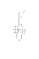
図5は、第1の実施形態におけるにおける端子の一例を示す正面図である。例えば、図5に示すように、第1の実施形態における端子70は、凹部78を形成する、一方向(図示の例では軸方向)に延在する2つの導電部である第1導電部71及び第2導電部72と、第2導電部72から一方向(軸方向)に突出した突出部としての外部接続端子73と、連結部74とを含む。 Figure 5 is a front view showing an example of a terminal in the first embodiment. For example, as shown in Figure 5, the terminal 70 in the first embodiment includes a first conductive part 71 and a second conductive part 72, which are two conductive parts extending in one direction (axial direction in the illustrated example) and form a recess 78, an external connection terminal 73 as a protruding part protruding in one direction (axial direction) from the second conductive part 72, and a connecting part 74.

2つの導電部である第1導電部71及び第2導電部72は、直接又は間接につながっている。例えば、2つの導電部である第1導電部71及び第2導電部72は、連結部74につながっており、この連結部74から分岐して形成される。第1導電部71及び第2導電部72は、軸方向と交差する方向(例えば、軸方向に直交する方向であり、図面では第1導電部71及び第2導電部72の一方から他方に向かう左右方向)において分岐し、凹部78を隔てて相互に対向する。凹部78は、例えば一方向(軸方向)に延在する。 The two conductive parts, the first conductive part 71 and the second conductive part 72, are directly or indirectly connected. For example, the two conductive parts, the first conductive part 71 and the second conductive part 72, are connected to a connecting part 74 and are formed by branching off from this connecting part 74. The first conductive part 71 and the second conductive part 72 branch off in a direction intersecting the axial direction (for example, a direction perpendicular to the axial direction, in the drawing, the left-right direction from one of the first conductive part 71 and the second conductive part 72 to the other) and face each other across a recess 78. The recess 78 extends, for example, in one direction (axial direction).

外部接続端子73は、第2導電部72から、軸方向に延在する。外部接続端子73には、例えば電源等の外部の装置や、他の端子に接続するための配線が電気的に接続される。 The external connection terminal 73 extends in the axial direction from the second conductive portion 72. The external connection terminal 73 is electrically connected to an external device such as a power source or a wiring for connecting to another terminal.

連結部74は、軸方向において、外部接続端子73とは反対の方向に延在する。連結部74は、インシュレータ10の挿入孔14に挿入される。連結部74には、複数の凹凸部74aが形成される。 The connecting portion 74 extends in the axial direction opposite to the external connection terminal 73. The connecting portion 74 is inserted into the insertion hole 14 of the insulator 10. The connecting portion 74 has a plurality of uneven portions 74a formed thereon.

また、第1の実施形態において、第1導電部71には、軸方向における外部接続端子73側(図面の上側)の部分に傾斜面71bが形成される。傾斜面71bは、第1導電部71と対向する第2導電部72が延在する方向に対して傾斜し、第2導電部72から離れて延在する。傾斜面71bと第2導電部72との距離は、例えば、連結部74から外部接続端子73に向かうにつれて大きくなっている。 In the first embodiment, the first conductive portion 71 has an inclined surface 71b formed on the axial side of the external connection terminal 73 (upper side in the drawing). The inclined surface 71b is inclined with respect to the direction in which the second conductive portion 72, which faces the first conductive portion 71, extends, and extends away from the second conductive portion 72. The distance between the inclined surface 71b and the second conductive portion 72 increases, for example, from the connecting portion 74 toward the external connection terminal 73.

また、第1の実施形態における第1導電部71は、外側面71cと、この外側面71cから突出した突起部71dとを含む。突起部71dは、例えば、第2導電部72側とは幅方向(図面の左右方向)において反対側に突出する。なお、第1導電部71の端部の幅は、突起部71dの幅を含んでも、第2導電部72の幅よりも小さい。すなわち、第1導電部71の曲げ剛性は第2導電部72の曲げ剛性よりも小さく、変形しやすい。 The first conductive part 71 in the first embodiment includes an outer surface 71c and a protrusion 71d protruding from the outer surface 71c. The protrusion 71d protrudes, for example, on the opposite side of the second conductive part 72 in the width direction (left-right direction in the drawing). The width of the end of the first conductive part 71 is smaller than the width of the second conductive part 72, even including the width of the protrusion 71d. In other words, the bending rigidity of the first conductive part 71 is smaller than the bending rigidity of the second conductive part 72, and is easily deformed.

第1の実施形態において、導線51は、例えば、耐熱性樹脂で被覆された、銅線等の電気伝導度の高い金属線により形成される。耐熱性樹脂で被覆された導線51を端子70に結線する際、一般的なはんだ付けでは処理温度が不足して被覆を溶かすことができない。そこで、第1の実施形態においては、端子70を形成する金属部材に電流を流して発熱させることにより、導線51の導体(金属線の部分)を露出させて端子との電気伝導を可能にさせるヒュージング処理(熱カシメ)が用いられる。 In the first embodiment, the conductor 51 is formed of a metal wire with high electrical conductivity, such as a copper wire, coated with a heat-resistant resin. When connecting the conductor 51 coated with heat-resistant resin to the terminal 70, the processing temperature is insufficient with ordinary soldering to melt the coating. Therefore, in the first embodiment, a fusing process (thermal crimping) is used in which an electric current is passed through the metal member forming the terminal 70 to generate heat, exposing the conductor (metal wire portion) of the conductor 51 and enabling electrical conduction with the terminal.

図6は、第1の実施形態における凹部への端子の溶着状態を示す正面図である。図6の(a)は、導線51がインシュレータ10の凹部18を介して、端子70の凹部78に挿入された状態を、径方向の内側から外側に向けて図示している。端子70と、端子70に挿入された導線51とは、端子70に対する熱カシメ処理により、図6の(b)に示すようにそれぞれ変形する。なお、図6において、導線51aは、熱カシメ処理により変形する前の導線51を示し、導線51bは、熱カシメ処理により変形した導線51を示す。同様に、端子70aは、熱カシメ処理により変形する前の端子70を示し、端子70bは、熱カシメ処理により変形した端子70を示す。 Figure 6 is a front view showing the state in which the terminal is welded to the recess in the first embodiment. Figure 6 (a) shows the state in which the conductor 51 is inserted into the recess 78 of the terminal 70 through the recess 18 of the insulator 10 from the inside to the outside in the radial direction. The terminal 70 and the conductor 51 inserted into the terminal 70 are deformed as shown in Figure 6 (b) by the thermal crimping process on the terminal 70. In Figure 6, the conductor 51a indicates the conductor 51 before it is deformed by the thermal crimping process, and the conductor 51b indicates the conductor 51 deformed by the thermal crimping process. Similarly, the terminal 70a indicates the terminal 70 before it is deformed by the thermal crimping process, and the terminal 70b indicates the terminal 70 deformed by the thermal crimping process.

第1の実施形態における熱カシメ処理は、例えば、凹部78に導線51aが挿入された端子70aの第1導電部71及び第2導電部72に、周方向の両側から電極58、59を押し付け、端子70aに電流を流すことにより行われる。その際、例えば、電極59は端子70の第2導電部72に接触した状態で固定され、電極58が、矢印Dに示す方向に端子70aの第1導電部71を押圧する。そして、電極58及び59から端子70aに電流が流されることにより、端子70aが発熱する。これにより、凹部78に挿入された導線51aの被覆が剥がされ、導線51と端子70とが溶着して電気的に接続される。また、端子70の第1導電部71も、電極58から圧力を受けて変形し、又は移動することで、第2導電部72と、部分77においてつながる。 In the first embodiment, the thermal crimping process is performed, for example, by pressing the electrodes 58 and 59 against the first conductive part 71 and the second conductive part 72 of the terminal 70a, in which the conductor 51a is inserted into the recess 78, from both sides in the circumferential direction, and passing a current through the terminal 70a. At that time, for example, the electrode 59 is fixed in contact with the second conductive part 72 of the terminal 70, and the electrode 58 presses the first conductive part 71 of the terminal 70a in the direction indicated by the arrow D. Then, the terminal 70a heats up as a result of passing a current from the electrodes 58 and 59 to the terminal 70a. As a result, the coating of the conductor 51a inserted into the recess 78 is peeled off, and the conductor 51 and the terminal 70 are welded together and electrically connected. The first conductive part 71 of the terminal 70 also deforms or moves under pressure from the electrode 58, and is connected to the second conductive part 72 at the portion 77.

また、端子70における発熱は、導線51を通じて、インシュレータ10の凹部18にも伝わる。この結果、例えば樹脂で形成された凹部18の一部が熱で溶けることにより、導線51とインシュレータ10とも溶着する。例えば、図6の(b)に示す部分52において、熱で被覆が剥がされ、変形した導線51bと、熱で一部が溶けたインシュレータ10の凹部18の底面18zとが溶着する。熱カシメ処理によって、これにより、導線51bはインシュレータ10の凹部18に固定されるので、モータ1の振動等が導線51bに伝わる場合においても、導線51bがインシュレータ10及び端子70bから外れることが抑制される。なお、図6においては、インシュレータ10の凹部18の底面18zが導線51bと溶着する例について説明したが、これに限られず、凹部18の側面18x又は18yが導線51bと溶着するような構成であってもよい。 The heat generated at the terminal 70 is also transmitted to the recess 18 of the insulator 10 through the conductor 51. As a result, a portion of the recess 18, which is made of resin, melts due to the heat, and the conductor 51 and the insulator 10 are also welded together. For example, at portion 52 shown in FIG. 6B, the coating is peeled off by the heat, and the deformed conductor 51b is welded to the bottom surface 18z of the recess 18 of the insulator 10, which is partially melted by the heat. The thermal crimping process fixes the conductor 51b to the recess 18 of the insulator 10, so that even if vibrations of the motor 1 are transmitted to the conductor 51b, the conductor 51b is prevented from coming off the insulator 10 and the terminal 70b. In addition, in FIG. 6, an example is described in which the bottom surface 18z of the recess 18 of the insulator 10 is welded to the conductor 51b, but this is not limited thereto, and the side surface 18x or 18y of the recess 18 may be welded to the conductor 51b.

以上説明したように、第1の実施形態におけるモータ1は、ステータ2を備える。ステータ2は、壁部12を有するインシュレータ10と、コイル50と、端子70とを備える。壁部12の一部には、凹部18が形成されており、コイル50を形成する導線51の一部は、インシュレータ10の凹部18を通過しており、導線51は端子70に電気接続している。かかる構成によれば、コイル50から引き出されて端子70に接続される導線51が、インシュレータ10の凹部18により保護されるので、モータ1における導線の断線を抑制できる。 As described above, the motor 1 in the first embodiment includes a stator 2. The stator 2 includes an insulator 10 having a wall portion 12, a coil 50, and a terminal 70. A recess 18 is formed in a portion of the wall portion 12, and a portion of the conductor 51 forming the coil 50 passes through the recess 18 of the insulator 10, and the conductor 51 is electrically connected to the terminal 70. With this configuration, the conductor 51 drawn from the coil 50 and connected to the terminal 70 is protected by the recess 18 of the insulator 10, so that breakage of the conductor in the motor 1 can be suppressed.

また、端子70は凹部78を備え、導線51は端子70の凹部78に接続されてもよい。その際、径方向において、インシュレータ10の凹部18と、端子70の凹部78とは対向するように配置される。これにより、コイル50から引き出された導線51を、容易に端子70の凹部78に引き回すことができる。 The terminal 70 may also have a recess 78, and the conductor 51 may be connected to the recess 78 of the terminal 70. In this case, the recess 18 of the insulator 10 and the recess 78 of the terminal 70 are arranged to face each other in the radial direction. This allows the conductor 51 drawn from the coil 50 to be easily routed to the recess 78 of the terminal 70.

また、インシュレータ10は外周部11を備え、回転軸方向において、外周部11は、端面11aが壁部12の端面12aよりも低くなるように形成されており、端子70は、外周部11に設けられてもよい。これにより、端子70を含むステータ2の軸方向における高さを削減することができる。 The insulator 10 also has an outer periphery 11, which is formed so that the end face 11a is lower than the end face 12a of the wall portion 12 in the direction of the rotation axis, and the terminal 70 may be provided on the outer periphery 11. This allows the height of the stator 2, including the terminal 70, in the axial direction to be reduced.

また、コイル50は、壁部12に対して、端子70がある側とは反対側に配置されていてもよい。かかる構成によれば、壁部12により、コイル50が端子70になだれ込むことを防ぐことができる。 The coil 50 may also be disposed on the opposite side of the wall 12 to the side on which the terminal 70 is located. With this configuration, the wall 12 can prevent the coil 50 from flowing into the terminal 70.

また、インシュレータ10を形成する部材と、導線51の一部とが接着していてもよい。これにより、導線51をより確実にインシュレータ10に固定させることができる。 Also, the member forming the insulator 10 and a part of the conductor 51 may be bonded together. This allows the conductor 51 to be more securely fixed to the insulator 10.

次に、本発明に係るその他の実施形態及び変形例について説明する。なお、以下の各実施形態及び各変形例において、先に説明した図面に示す部位と同一の部位には同一の符号を付し、重複する説明は省略する。 Next, other embodiments and modifications of the present invention will be described. In each of the following embodiments and modifications, the same parts as those shown in the drawings described above will be given the same reference numerals, and duplicated descriptions will be omitted.

[第2の実施形態]
第2の実施形態におけるインシュレータ20は、端子70が複数挿入される点において、第1の実施形態におけるインシュレータ10とは異なる。図7Aは、第2の実施形態における端子が装着されたインシュレータの一例を示す正面斜視図である。図7Bは、第2の実施形態における端子が装着されたインシュレータの一例を示す背面斜視図である。図8は、第2の実施形態におけるインシュレータの一例を示す背面斜視図である。図7A乃至図8に示すように、インシュレータ20は、外周部21と、壁部22と、内周部13と、2つの挿入孔24m、24nと、接続部15と、2つの凹部28、29と、を備える。インシュレータ20の挿入孔24m、24nには、それぞれ端子70m、70nが挿入される。
Second Embodiment
The insulator 20 in the second embodiment differs from the insulator 10 in the first embodiment in that a plurality of terminals 70 are inserted into the insulator 20. Fig. 7A is a front perspective view showing an example of the insulator to which the terminals in the second embodiment are attached. Fig. 7B is a rear perspective view showing an example of the insulator to which the terminals in the second embodiment are attached. Fig. 8 is a rear perspective view showing an example of the insulator in the second embodiment. As shown in Figs. 7A to 8, the insulator 20 includes an outer peripheral portion 21, a wall portion 22, an inner peripheral portion 13, two insertion holes 24m, 24n, a connection portion 15, and two recesses 28, 29. Terminals 70m, 70n are inserted into the insertion holes 24m, 24n of the insulator 20, respectively.

すなわち、第2の実施形態において、インシュレータ20には、複数の端子70m、70nが挿入されるとともに、端子と同数の凹部28、29が形成される。この場合においても、第1の実施形態と同様に、インシュレータ20の凹部28は、端子70mの凹部78mと対向し、インシュレータ20の凹部29は、端子70nの凹部78nと対向する。また、例えば、コイル50から複数の導線51が引き出される場合において、1つの導線51は凹部28を介して端子70mに電気的に接続され、他の1つの導線51は凹部29を介して端子70nに電気的に接続される。 That is, in the second embodiment, multiple terminals 70m, 70n are inserted into the insulator 20, and the same number of recesses 28, 29 are formed as the number of terminals. In this case, as in the first embodiment, the recess 28 of the insulator 20 faces the recess 78m of the terminal 70m, and the recess 29 of the insulator 20 faces the recess 78n of the terminal 70n. Also, for example, when multiple conductors 51 are drawn out from the coil 50, one conductor 51 is electrically connected to the terminal 70m via the recess 28, and the other conductor 51 is electrically connected to the terminal 70n via the recess 29.

以上説明したように、第2の実施形態において、インシュレータ20の壁部22には、複数の凹部28、29が形成され、外周部21には、複数の端子70m、70nが設けられる。これにより、1つのインシュレータ20に対し、複数の端子70を設ける場合においても、複数の導線51が、インシュレータ20の凹部28、29によりそれぞれ保護されるので、モータ1における導線の断線を抑制できる。 As described above, in the second embodiment, the wall portion 22 of the insulator 20 is formed with multiple recesses 28, 29, and multiple terminals 70m, 70n are provided on the outer periphery 21. As a result, even when multiple terminals 70 are provided on one insulator 20, the multiple conductors 51 are each protected by the recesses 28, 29 of the insulator 20, so that breakage of the conductors in the motor 1 can be suppressed.

[第3の実施形態]
第1の実施形態において、インシュレータ10の外周部11は、周方向における中央付近において、径方向における厚みが最大になるように形成される。この場合において、外周部11に端子70を挿入する際、外周部11の厚みが大きくなる部分に、端子70が挿入されることが、インシュレータ10の強度上好ましい。
[Third embodiment]
In the first embodiment, the outer circumferential portion 11 of the insulator 10 is formed so that the radial thickness is greatest near the center in the circumferential direction. In this case, when inserting the terminal 70 into the outer circumferential portion 11, it is preferable in terms of the strength of the insulator 10 that the terminal 70 is inserted into the portion of the outer circumferential portion 11 where the thickness is greatest.

そこで、第3の実施形態におけるインシュレータ30は、第1の実施形態におけるインシュレータ10の凹部18とは異なり、凹部38が径方向に延在するのではなく、図9に示すように、径方向に対して斜めに形成される。図9は、第3の実施形態における端子が装着されたインシュレータの一例を示す斜視図である。図9に示すように、第3の実施形態におけるインシュレータ30は、ティース3aに、軸方向における上方向から装着される。また、第3の実施形態において、インシュレータ10は、例えば、ステータコア3のティース3aに、軸方向における下方向から装着される部位40をさらに含む。 Therefore, unlike the recess 18 of the insulator 10 in the first embodiment, the insulator 30 in the third embodiment has a recess 38 that does not extend radially, but is formed at an angle to the radial direction as shown in FIG. 9. FIG. 9 is a perspective view showing an example of an insulator to which a terminal in the third embodiment is attached. As shown in FIG. 9, the insulator 30 in the third embodiment is attached to the teeth 3a from above in the axial direction. Furthermore, in the third embodiment, the insulator 10 further includes a portion 40 that is attached to the teeth 3a of the stator core 3 from below in the axial direction, for example.

図9に示すように、インシュレータ30は、外周部31と、壁部32と、内周部13と、2つの挿入孔34m、34nと、接続部35と、2つの凹部38、39と、を備える。インシュレータ30の挿入孔34m、34nには、それぞれ端子70m、70nが挿入される。図9に示すように、第3の実施形態におけるインシュレータ30において、凹部38は、径方向における外側に向かう際に、外周部31の周縁部付近から中央付近に近づくように、径方向に対して斜めに形成される。なお、第3の実施形態における接続部35は、形状以外は接続部15と同様の構成を有するため、詳細な説明は省略する。 As shown in FIG. 9, the insulator 30 includes an outer periphery 31, a wall 32, an inner periphery 13, two insertion holes 34m, 34n, a connection portion 35, and two recesses 38, 39. Terminals 70m, 70n are inserted into the insertion holes 34m, 34n of the insulator 30, respectively. As shown in FIG. 9, in the insulator 30 of the third embodiment, the recesses 38 are formed at an angle to the radial direction so that they move from near the periphery of the outer periphery 31 toward the center as they move radially outward. Note that the connection portion 35 of the third embodiment has the same configuration as the connection portion 15 except for its shape, so a detailed description will be omitted.

第3の実施形態においても、端子70は、インシュレータ30の外周部31に形成された挿入孔34m、34nに挿入される。また、端子70は、凹部78が、インシュレータ30の凹部38と対向するように配置される。すなわち、第3の実施形態における端子70は、第1の実施形態における端子70よりも、周方向において、外周部31の中央付近に設けられる。かかる構成においては、端子70が挿入される挿入孔34mを、外周部31において、径方向における厚みが大きくなる位置に形成することができる。これにより、端子70がインシュレータ30に挿入された際の安定性を強化することができる。 In the third embodiment, the terminal 70 is also inserted into the insertion holes 34m, 34n formed in the outer periphery 31 of the insulator 30. The terminal 70 is arranged so that the recess 78 faces the recess 38 of the insulator 30. That is, the terminal 70 in the third embodiment is provided closer to the center of the outer periphery 31 in the circumferential direction than the terminal 70 in the first embodiment. In this configuration, the insertion hole 34m into which the terminal 70 is inserted can be formed in a position in the outer periphery 31 where the thickness in the radial direction is greater. This enhances the stability of the terminal 70 when it is inserted into the insulator 30.

また、第3の実施形態において、インシュレータ30の凹部38の側面38x、38yには、図10に示すように、突出した凸部38a、38bが形成されていてもよい。図10は、第3の実施形態における端子が装着されたインシュレータの一例を示す拡大斜視図である。図10は、図9の領域Fで示される部分の拡大図である。かかる構成において、径方向における内側から凹部38に挿通される導線51は、まず、側面38xに形成された凸部38aにより、周方向において、外周部31の中央付近へと向かうように屈曲する。すなわち、凸部38aは、導線51を、凹部38の内周部側から外周部側へとガイドするガイド部として作用する。 In the third embodiment, the side surfaces 38x and 38y of the recess 38 of the insulator 30 may have protruding convex portions 38a and 38b formed thereon, as shown in FIG. 10. FIG. 10 is an enlarged perspective view showing an example of an insulator to which a terminal is attached in the third embodiment. FIG. 10 is an enlarged view of a portion shown by region F in FIG. 9. In this configuration, the conductor 51 inserted into the recess 38 from the inside in the radial direction is first bent in the circumferential direction by the convex portion 38a formed on the side surface 38x so as to move toward the center of the outer periphery 31. In other words, the convex portion 38a acts as a guide portion that guides the conductor 51 from the inner periphery side to the outer periphery side of the recess 38.

第3の実施形態において、インシュレータ30の凸部38aによりガイドされた導線51は、側面38yに形成された凸部38bにより、凹部38と対向する端子70の凹部78へと向かうように、さらに屈曲する。すなわち、凸部38bも、導線51を、凹部38の内周部側から外周部側へとガイドするガイド部として作用する。 In the third embodiment, the conductor 51 guided by the convex portion 38a of the insulator 30 is further bent by the convex portion 38b formed on the side surface 38y so as to be directed toward the concave portion 78 of the terminal 70 that faces the concave portion 38. In other words, the convex portion 38b also acts as a guide portion that guides the conductor 51 from the inner peripheral side to the outer peripheral side of the concave portion 38.

なお、図9に示すように、第3の実施形態におけるインシュレータ30には、第2の実施形態におけるインシュレータ20と同様に、複数の端子70が挿入されていてもよい。この場合において、インシュレータ30の凹部は、インシュレータ30に挿入される端子70の数に応じて形成されてもよい。図9に示すように、例えば、端子70が2つ挿入されるインシュレータ30には、2つの凹部38、39が形成される。 As shown in FIG. 9, the insulator 30 in the third embodiment may have multiple terminals 70 inserted therein, similar to the insulator 20 in the second embodiment. In this case, the recesses in the insulator 30 may be formed according to the number of terminals 70 to be inserted therein. As shown in FIG. 9, for example, two recesses 38 and 39 are formed in the insulator 30 into which two terminals 70 are inserted.

以上説明したように、第3の実施形態において、インシュレータ30の凹部38は、モータ1の径方向に対して斜めに形成され、径方向において、インシュレータ30の凹部38と、端子70の凹部98とは対向していてもよい。この際、インシュレータ30の凹部38には凸部38a、38bが形成され、インシュレータ30の凹部38に挿入された導線51は、凸部38a、38bにより進行方向が変化してもよい。かかる構成によれば、端子70の挿入孔34m又は34nを、径方向における厚みが大きくなる外周部31の中央部付近に設ける場合においても、コイル50から引き出された導線51を容易に端子70に接続させることができる。 As described above, in the third embodiment, the recess 38 of the insulator 30 may be formed at an angle to the radial direction of the motor 1, and the recess 38 of the insulator 30 and the recess 98 of the terminal 70 may face each other in the radial direction. In this case, the recess 38 of the insulator 30 may have protrusions 38a and 38b formed therein, and the direction of the conductor 51 inserted into the recess 38 of the insulator 30 may be changed by the protrusions 38a and 38b. With this configuration, even if the insertion hole 34m or 34n of the terminal 70 is provided near the center of the outer periphery 31 where the thickness in the radial direction is large, the conductor 51 drawn from the coil 50 can be easily connected to the terminal 70.

また、コイル50から引き出される導線51は、インシュレータ10の周方向における周縁部付近に引き出された場合でも、導線51の断線の発生を抑止できる。また、インシュレータ10の凹部18から径方向における外側に引き出された導線51を、インシュレータ10の外周部11の中央付近に挿入された端子70に接続させる際、コイル50と端子70との間の距離が大きくなっても、導線51の断線の発生を抑止できる。 In addition, even if the conductor 51 drawn from the coil 50 is drawn near the peripheral edge of the insulator 10 in the circumferential direction, the occurrence of breakage of the conductor 51 can be prevented. Furthermore, when the conductor 51 drawn outward in the radial direction from the recess 18 of the insulator 10 is connected to the terminal 70 inserted near the center of the outer periphery 11 of the insulator 10, even if the distance between the coil 50 and the terminal 70 becomes large, the occurrence of breakage of the conductor 51 can be prevented.

また、凹部38が、導線51を、インシュレータ30の周方向における周縁部付近から中央付近にガイドする構成について説明したが、実施の形態はこれに限られない。図9に示すように、例えば、凹部39が、径方向における外側に向かう際に、外周部31の中央付近から周縁部付近に近づくように、径方向に対して斜めに形成されていてもよい。この場合、導線51は、インシュレータ30の周方向における中央付近から周縁部付近にガイドされる。 Although the recess 38 has been described as guiding the conductor 51 from near the peripheral edge to near the center in the circumferential direction of the insulator 30, the embodiment is not limited to this. As shown in FIG. 9, for example, the recess 39 may be formed at an angle to the radial direction so that it approaches from near the center of the outer circumferential portion 31 to near the peripheral edge as it moves radially outward. In this case, the conductor 51 is guided from near the center to near the peripheral edge in the circumferential direction of the insulator 30.

また、凹部38が、モータ1の径方向に対して斜めに形成される例について説明したが、例えば、凹部38は、モータ1の軸方向に対して斜めに形成されていてもよい。すなわち、壁部32の内周側と外周側とで、凹部38の底面の高さが異なるような構成であってもよい。これにより、例えば、端子70の凹部78の底面の高さに合わせて、導線51をガイドすることができる。 Although an example has been described in which the recess 38 is formed at an angle to the radial direction of the motor 1, for example, the recess 38 may be formed at an angle to the axial direction of the motor 1. In other words, the height of the bottom surface of the recess 38 may be different on the inner and outer circumferential sides of the wall portion 32. This allows the conductor 51 to be guided to match the height of the bottom surface of the recess 78 of the terminal 70, for example.

以上、本発明の実施形態について説明したが、本発明は上記実施形態に限定されるものではなく、その趣旨を逸脱しない限りにおいて種々の変更が可能である。例えば、端子70の形状は上記したものに限られず、任意の形状とすることができる。図11Aは、変形例における端子の一例を示す正面図である。例えば、図11Aに示すように、変形例における端子80は、第1導電部81及び第2導電部82と、外部接続端子73と、連結部74と、凹部88とを含む。 Although the embodiment of the present invention has been described above, the present invention is not limited to the above embodiment, and various modifications are possible without departing from the spirit of the present invention. For example, the shape of the terminal 70 is not limited to the above, and can be any shape. FIG. 11A is a front view showing an example of a terminal in a modified example. For example, as shown in FIG. 11A, the terminal 80 in the modified example includes a first conductive portion 81 and a second conductive portion 82, an external connection terminal 73, a connecting portion 74, and a recess 88.

第1導電部81及び第2導電部82は、軸方向と交差する方向(例えば、軸方向に直交する方向であり、図面では第1導電部81及び第2導電部82の一方から他方に向かう左右方向)において分岐し、凹部88を隔てて相互に対向する。凹部88は、例えば一方向(軸方向)に延在する。第1の実施形態において、凹部88の幅は、例えば、導線51の外形よりもやや小さく設定される。 The first conductive portion 81 and the second conductive portion 82 branch off in a direction intersecting the axial direction (for example, a direction perpendicular to the axial direction, which in the drawings is a left-right direction from one of the first conductive portion 81 and the second conductive portion 82 to the other) and face each other across the recess 88. The recess 88 extends, for example, in one direction (axial direction). In the first embodiment, the width of the recess 88 is set, for example, slightly smaller than the outer shape of the conductor 51.

図11Aに示すように、本変形例において、外部接続端子73が延在する方向(図面の上下方向)と直交する方向(図面の左右方向)における、端子80の第1導電部81の幅W1は、第2導電部82の幅W2よりも小さくなるように形成される。 As shown in FIG. 11A, in this modified example, the width W1 of the first conductive portion 81 of the terminal 80 in the direction perpendicular to the direction in which the external connection terminal 73 extends (the vertical direction in the drawing) (the horizontal direction in the drawing) is formed to be smaller than the width W2 of the second conductive portion 82.

第1の実施形態において、第1導電部81及び第2導電部82の一方には第1凹部81aがあり、第1導電部81及び第2導電部82の他方には第2凹部82aがある。第2凹部82aの外形は、第1凹部81aの外形と同じか、又は小さい。第1凹部81aと第2凹部82aとは対向している。具体的には、図11Aに示すように、第1導電部81の第2導電部82と対向する面には、第1凹部81aが形成される。同様に、第2導電部82の第1導電部81と対向する面には、第2凹部82aが形成される。第1の実施形態においては、第1凹部81a及び第2凹部82aは、正面視においてそれぞれ略半円弧状に形成され、また相互に対向して形成される。これにより、第1凹部81a及び第2凹部82aは、熱カシメ処理により、合わさって略楕円形状を形成する。変形例において、導線51は、第1凹部81aと第2凹部82aとに挟まれた領域に固定される。 In the first embodiment, one of the first conductive portion 81 and the second conductive portion 82 has a first recess 81a, and the other of the first conductive portion 81 and the second conductive portion 82 has a second recess 82a. The outer shape of the second recess 82a is the same as or smaller than the outer shape of the first recess 81a. The first recess 81a and the second recess 82a are opposed to each other. Specifically, as shown in FIG. 11A, the first recess 81a is formed on the surface of the first conductive portion 81 facing the second conductive portion 82. Similarly, the second recess 82a is formed on the surface of the second conductive portion 82 facing the first conductive portion 81. In the first embodiment, the first recess 81a and the second recess 82a are each formed in an approximately semicircular arc shape when viewed from the front, and are also formed opposite each other. As a result, the first recess 81a and the second recess 82a are joined together to form an approximately elliptical shape by thermal caulking. In the modified example, the conductor 51 is fixed in the area between the first recess 81a and the second recess 82a.

また、第1の実施形態においては、図11Aに示すように、第1凹部81aと第2凹部82aとは、軸方向において、高さが相互に異なる。具体的には、軸方向において、第1凹部81aは、第2凹部82aよりも上方向に位置する。なお、変形例はこれに限られず、例えば、軸方向において、第2凹部82aが、第1凹部81aよりも上方向に位置するような構成であってもよい。 In the first embodiment, as shown in FIG. 11A, the first recess 81a and the second recess 82a have different heights in the axial direction. Specifically, the first recess 81a is located higher than the second recess 82a in the axial direction. Note that the modified example is not limited to this, and for example, the second recess 82a may be located higher than the first recess 81a in the axial direction.

図11Bは、別の変形例における端子の一例を示す正面図である。別の変形例における端子90は、第1導電部91及び第2導電部92と、外部接続端子73と、連結部74と、凹部98とを含む。別の変形例における第1導電部91は、図11Aに示す端子80の第1導電部81と同様に、第1凹部91aを含む。また、別の変形例における第2導電部92は、図11Aに示す端子80の第2導電部82と同様に、第2凹部92aを含む。別の変形例においても、導線51は、第1凹部81aと第2凹部82aとに挟まれた領域に固定される。 Figure 11B is a front view showing an example of a terminal in another modified example. The terminal 90 in another modified example includes a first conductive portion 91 and a second conductive portion 92, an external connection terminal 73, a connecting portion 74, and a recess 98. The first conductive portion 91 in another modified example includes a first recess 91a, similar to the first conductive portion 81 of the terminal 80 shown in Figure 11A. The second conductive portion 92 in another modified example includes a second recess 92a, similar to the second conductive portion 82 of the terminal 80 shown in Figure 11A. In the other modified example, the conductor 51 is also fixed in the region between the first recess 81a and the second recess 82a.

別の変形例における端子90において、凹部98は、モータ1の回転軸方向において、第1導電部91及び第2導電部92が分岐する部分に向かう方向に対して、第2導電部92から離れる方向に傾斜している部分97を有する。 In another modified terminal 90, the recess 98 has a portion 97 that is inclined in the direction of the rotation axis of the motor 1 away from the second conductive portion 92 with respect to the direction toward the portion where the first conductive portion 91 and the second conductive portion 92 branch off.

また、インシュレータ10、20、30の凹部18、28、29、38、39には、当該インシュレータに巻き回されたコイル50から引き出された導線51が挿通される構成について説明したが、これに限れない。例えば、他のインシュレータ10、20、30に巻き回されたコイル50から引き出された導線51や、他の端子70、80、90に接続された導線51が、凹部18、28、29、38、39に挿通されるような構成であってもよい。 In addition, the configuration has been described in which the conductor 51 drawn from the coil 50 wound around the insulator is inserted into the recesses 18, 28, 29, 38, 39 of the insulator 10, 20, 30, but this is not limited to the configuration. For example, the conductor 51 drawn from the coil 50 wound around another insulator 10, 20, 30 or the conductor 51 connected to another terminal 70, 80, 90 may be inserted into the recesses 18, 28, 29, 38, 39.

また、上述した実施形態では、モータ1が車載用に用いられるインナーロータ型のブラシレスモータである場合について説明したが、モータ1は、車載用以外に用いられるモータであってもよく、アウターロータ型のブラシレスモータであってもよく、またブラシ付きモータやステッピングモータなどの公知の他のモータであってもよい。 In the above embodiment, the motor 1 is an inner rotor type brushless motor used for vehicle applications, but the motor 1 may be a motor used for purposes other than vehicle applications, an outer rotor type brushless motor, or other known motors such as a brushed motor or a stepping motor.

また、上記実施の形態により本発明が限定されるものではない。上述した各構成要素を適宜組み合わせて構成したものも本発明に含まれる。また、さらなる変形例は、当業者によって容易に導き出すことができる。よって、本発明のより広範な態様は、上記の実施の形態に限定されるものではなく、様々な変更が可能である。 Furthermore, the present invention is not limited to the above-mentioned embodiment. The present invention also includes configurations in which the above-mentioned components are appropriately combined. Further modifications can be easily derived by those skilled in the art. Therefore, the broader aspects of the present invention are not limited to the above-mentioned embodiment, and various modifications are possible.

1 モータ、2 ステータ、3 ステータコア、10,20,30 インシュレータ、11,21,31 外周部、12,22,32 壁部、13 内周部、14,24m,24n,34m,34n 挿入孔、15,35 接続部、18,28,29,38,39 凹部、50 コイル、51 導線、61 フレーム、62 ロータ、63 回転軸(シャフト)、70,80,90 端子、78,88,98 凹部 1 motor, 2 stator, 3 stator core, 10, 20, 30 insulator, 11, 21, 31 outer periphery, 12, 22, 32 wall, 13 inner periphery, 14, 24m, 24n, 34m, 34n insertion hole, 15, 35 connection, 18, 28, 29, 38, 39 recess, 50 coil, 51 conductor, 61 frame, 62 rotor, 63 rotating shaft, 70, 80, 90 terminal, 78, 88, 98 recess

Claims (8)

ステータを備え、
前記ステータは、
壁部を有するインシュレータと、
コイルと、
端子と、
を備え、
前記端子は、前記インシュレータに装着される連結部と、当該連結部から分岐した第1導電部および第2導電部と、当該第1導電部と当該第2導電部とで形成される凹部と、を備え、
前記壁部の一部には、凹部が形成されており、
前記コイルを形成する導線の一部は、前記インシュレータの凹部を通過しており、
前記導線は前記端子に電気接続し、
前記導線は前記端子の凹部に接続されている、
モータ。
A stator is provided.
The stator includes:
an insulator having a wall portion;
A coil and
The terminals and
Equipped with
the terminal includes a connecting portion attached to the insulator, a first conductive portion and a second conductive portion branched from the connecting portion, and a recess formed by the first conductive portion and the second conductive portion,
A recess is formed in a portion of the wall,
A portion of the conductor forming the coil passes through a recess in the insulator,
the conductor is electrically connected to the terminal ;
The conductive wire is connected to the recess of the terminal.
Motor.
径方向において、前記インシュレータの凹部と、前記端子の凹部とは対向している、請求項に記載のモータ。 The motor according to claim 1 , wherein the recess of the insulator and the recess of the terminal face each other in a radial direction. 前記インシュレータは外周部を備え、
回転軸方向において、前記外周部は、端面が前記壁部の端面よりも低くなるように形成されており、
前記端子は、前記外周部に設けられている、
請求項1又は2に記載のモータ。
The insulator has an outer periphery,
In the rotation axis direction, the outer circumferential portion is formed such that an end face is lower than an end face of the wall portion,
The terminal is provided on the outer periphery.
3. The motor according to claim 1 or 2 .
前記コイルは、前記壁部に対して、前記端子がある側とは反対側に配置されている、請求項1乃至3のいずれか1つに記載のモータ。 The motor according to claim 1 , wherein the coil is disposed on an opposite side of the wall portion to a side on which the terminal is disposed. 前記インシュレータを形成する部材と、前記インシュレータの凹部を通過する前記導線の一部とが接着している、請求項1乃至4のいずれか1つに記載のモータ。 5. The motor according to claim 1, wherein a member forming the insulator and a part of the conductor passing through a recess of the insulator are bonded to each other. 前記インシュレータは、外周部を備え、
前記壁部には、前記凹部を含む複数の凹部が形成され、
前記外周部には、前記端子を含む複数の端子が設けられる、請求項1乃至5のいずれか1つに記載のモータ。
The insulator has an outer periphery,
A plurality of recesses including the recess are formed in the wall portion ,
The motor according to claim 1 , wherein a plurality of terminals including the terminal are provided on the outer circumferential portion.
前記インシュレータの凹部は、前記モータの径方向に対して斜めに形成され、
径方向において、前記インシュレータの凹部と、前記端子の凹部とは対向している、請求項1乃至6のいずれか1つに記載のモータ。
The recess of the insulator is formed obliquely with respect to a radial direction of the motor,
7. The motor according to claim 1 , wherein the recess of the insulator and the recess of the terminal face each other in a radial direction.
前記インシュレータの凹部には凸部が形成され、
前記インシュレータの凹部に挿入された前記導線は、前記凸部により進行方向が変化する、請求項に記載のモータ。
A protrusion is formed in the recess of the insulator,
The motor according to claim 7 , wherein the direction of travel of the conductor inserted into the recess of the insulator is changed by the protrusion.
JP2020152985A 2020-09-11 2020-09-11 Motor Active JP7561551B2 (en)

Priority Applications (1)

Application Number Priority Date Filing Date Title
JP2020152985A JP7561551B2 (en) 2020-09-11 2020-09-11 Motor

Applications Claiming Priority (1)

Application Number Priority Date Filing Date Title
JP2020152985A JP7561551B2 (en) 2020-09-11 2020-09-11 Motor

Publications (2)

Publication Number Publication Date
JP2022047205A JP2022047205A (en) 2022-03-24
JP7561551B2 true JP7561551B2 (en) 2024-10-04

Family

ID=80780217

Family Applications (1)

Application Number Title Priority Date Filing Date
JP2020152985A Active JP7561551B2 (en) 2020-09-11 2020-09-11 Motor

Country Status (1)

Country Link
JP (1) JP7561551B2 (en)

Citations (3)

* Cited by examiner, † Cited by third party
Publication number Priority date Publication date Assignee Title
JP2006280155A (en) 2005-03-30 2006-10-12 Honda Motor Co Ltd Rotating electric machine and manufacturing method thereof
JP2011205817A (en) 2010-03-26 2011-10-13 Aisin Seiki Co Ltd Stator for rotary electrical machine
JP2018207616A (en) 2017-05-31 2018-12-27 ミネベアミツミ株式会社 motor

Family Cites Families (1)

* Cited by examiner, † Cited by third party
Publication number Priority date Publication date Assignee Title
JPS55150655U (en) * 1979-04-12 1980-10-30

Patent Citations (3)

* Cited by examiner, † Cited by third party
Publication number Priority date Publication date Assignee Title
JP2006280155A (en) 2005-03-30 2006-10-12 Honda Motor Co Ltd Rotating electric machine and manufacturing method thereof
JP2011205817A (en) 2010-03-26 2011-10-13 Aisin Seiki Co Ltd Stator for rotary electrical machine
JP2018207616A (en) 2017-05-31 2018-12-27 ミネベアミツミ株式会社 motor

Also Published As

Publication number Publication date
JP2022047205A (en) 2022-03-24

Similar Documents

Publication Publication Date Title
JP6727457B1 (en) Stator and electric motor
CN113809862B (en) Power distribution components
CN104541437A (en) Stator unit and motor
JP4486678B2 (en) Rotating motor armature, rotating motor and manufacturing method thereof
US10418864B2 (en) Stator core
JP7561551B2 (en) Motor
JP5237767B2 (en) Commutator, armature and motor including the commutator, method for manufacturing the armature, and method for manufacturing the motor
CN114902537A (en) Motor
JP7268541B2 (en) Wiring member for rotary electric machine and its fixing structure
CN110692180B (en) motor
JP7405089B2 (en) motor
CN115349214A (en) Motor
US12348096B2 (en) Coil having segment conductors welded with a welded metal portion
JP7469104B2 (en) Terminals
JP7268542B2 (en) Arrangement structure of wiring members for rotary electric machine
JP7631634B2 (en) Stator, motor, and method for manufacturing a stator
JP7205505B2 (en) power distribution material
JP7429521B2 (en) motor
CN115315887A (en) Motor
JP7503378B2 (en) motor
JP2017212781A (en) Rotary electric machine
JP7437403B2 (en) motor
CN118216067A (en) Motor
JP2024041555A (en) Stator and stator manufacturing method
JP2026002236A (en) Motor

Legal Events

Date Code Title Description
A621 Written request for application examination

Free format text: JAPANESE INTERMEDIATE CODE: A621

Effective date: 20230824

A977 Report on retrieval

Free format text: JAPANESE INTERMEDIATE CODE: A971007

Effective date: 20240215

A131 Notification of reasons for refusal

Free format text: JAPANESE INTERMEDIATE CODE: A131

Effective date: 20240305

A521 Request for written amendment filed

Free format text: JAPANESE INTERMEDIATE CODE: A523

Effective date: 20240502

TRDD Decision of grant or rejection written
A01 Written decision to grant a patent or to grant a registration (utility model)

Free format text: JAPANESE INTERMEDIATE CODE: A01

Effective date: 20240828

A61 First payment of annual fees (during grant procedure)

Free format text: JAPANESE INTERMEDIATE CODE: A61

Effective date: 20240924

R150 Certificate of patent or registration of utility model

Ref document number: 7561551

Country of ref document: JP

Free format text: JAPANESE INTERMEDIATE CODE: R150