JP7601330B2 - Scintillator and radiation measuring device - Google Patents
Scintillator and radiation measuring device Download PDFInfo
- Publication number
- JP7601330B2 JP7601330B2 JP2021028343A JP2021028343A JP7601330B2 JP 7601330 B2 JP7601330 B2 JP 7601330B2 JP 2021028343 A JP2021028343 A JP 2021028343A JP 2021028343 A JP2021028343 A JP 2021028343A JP 7601330 B2 JP7601330 B2 JP 7601330B2
- Authority
- JP
- Japan
- Prior art keywords
- scintillator
- crystal
- crystal phase
- eutectic
- light
- Prior art date
- Legal status (The legal status is an assumption and is not a legal conclusion. Google has not performed a legal analysis and makes no representation as to the accuracy of the status listed.)
- Active
Links
Images
Landscapes
- Measurement Of Radiation (AREA)
- Luminescent Compositions (AREA)
Description
本発明は、シンチレータおよび放射線測定装置に関する。 The present invention relates to a scintillator and a radiation measuring device.
中性子線検出器(測定装置)の応用分野は、有機物・無機物に対する結晶構造解析、中性子線を用いたホウ素中性子捕捉療法などの医療技術、高エネルギー放射光施設での中性子線検出、非破壊検査分野、あるいは貨物検査等の保安分野等多岐にわたる。また、中性子利用技術の発展に伴い、より感度の高い中性子検出器が求められている。 Neutron detectors (measuring devices) have a wide range of application areas, including crystal structure analysis of organic and inorganic substances, medical technologies such as boron neutron capture therapy using neutron beams, neutron beam detection at high-energy synchrotron radiation facilities, non-destructive testing, and security fields such as cargo inspection. Furthermore, with the development of neutron utilization technology, there is a demand for more sensitive neutron detectors.
例えば特許文献1記載には、Ce添加Cs2LiYCl6の化合物単結晶が、発光量が1中性子あたり73000光子である中性子シンチレータとして開示されている。 For example, Patent Document 1 discloses a single crystal of a Ce-doped Cs 2 LiYCl 6 compound as a neutron scintillator that emits light at an amount of 73,000 photons per neutron.
また、例えば、特許文献2および非特許文献1には、フッ化リチウム結晶とフッ化カルシウム結晶、フッ化ストロンチウムからなる共晶体に、発光中心元素としてCeあるいはEuを含有させ、フッ化カルシウムやフッ化リチウムが放射線励起により発光する共晶体が開示されている。 For example, Patent Document 2 and Non-Patent Document 1 disclose a eutectic consisting of lithium fluoride crystals, calcium fluoride crystals, and strontium fluoride, which contains Ce or Eu as a luminescent center element, and in which calcium fluoride and lithium fluoride emit light when excited by radiation.
しかしながら、特許文献1に係る技術では、単結晶であることから透明度が高く、かつ発光量が高いものの、化合物単結晶の化学組成が限定されるため、Liの含有量を高めることができない。このため、特許文献1に係る技術では、Cs2LiYCl6におけるLiのモル含有率は10%と低いため中性子線に対する感度が低いという問題がある。 However, in the technology of Patent Document 1, although the transparency is high and the amount of light emitted is high because it is a single crystal, the chemical composition of the compound single crystal is limited, so that the Li content cannot be increased. Therefore, in the technology of Patent Document 1 , the molar content of Li in Cs2LiYCl6 is low at 10%, so that there is a problem that the sensitivity to neutron rays is low.
一方、特許文献2および非特許文献1に係る技術では、層状のフッ化リチウム結晶と層状のフッ化カルシウム結晶、フッ化ストロンチウム結晶とが交互に積層した共晶体シンチレータとなっており、フッ化カルシウム結晶やフッ化ストロンチウム結晶が放射線励起により発光する構造となっている。ここで、フッ化リチウム結晶と、層状のフッ化カルシウムと、フッ化ストロンチウムとの屈折率の差が発光波長において0.04以上と大きい。このため、この技術では、放射線励起により発光した光が、各結晶相の間で、散乱、吸収されるため、透過率が低下し、シンチレーション光がシンチレータ内で減衰して受光素子に到達することから、発光量が低下するという問題がある。 On the other hand, the technology disclosed in Patent Document 2 and Non-Patent Document 1 uses a eutectic scintillator in which layered lithium fluoride crystals, layered calcium fluoride crystals, and strontium fluoride crystals are alternately stacked, and the calcium fluoride crystals and strontium fluoride crystals emit light when excited by radiation. Here, the difference in refractive index between the lithium fluoride crystals and the layered calcium fluoride and strontium fluoride is large, at 0.04 or more at the emission wavelength. For this reason, this technology has a problem in that the light emitted by radiation excitation is scattered and absorbed between the crystal phases, reducing the transmittance, and the scintillation light is attenuated within the scintillator before reaching the light receiving element, reducing the amount of light emitted.
上述したように、従来の技術では、高い感度および発光量を得ることができないという問題があった。 As mentioned above, conventional technology has the problem of being unable to achieve high sensitivity and light emission.
本発明は、以上のような問題点を解消するためになされたものであり、高い感度および発光量が得られるシンチレータの提供を目的とする。 The present invention was made to solve the above problems, and aims to provide a scintillator that provides high sensitivity and light emission.
本発明に係るシンチレータは、Liを含有する第1結晶相および放射線励起で発光する第2結晶相を含む複数の結晶相からなる共晶体から構成され、複数の結晶相の各々は、互いの屈折率差が0.04以下である。 The scintillator according to the present invention is composed of a eutectic consisting of multiple crystalline phases, including a first crystalline phase containing Li and a second crystalline phase that emits light when excited by radiation, and each of the multiple crystalline phases has a refractive index difference of 0.04 or less.
上記シンチレータの一構成例において、第2結晶相は、発光中心としてPr、Ce、Nd、Sm、Eu、Gd、Tb、Dy、Ho、Dy、Er、Tm、Yb、Tl、Pb、Bi、Ag,Ti,Crのうち少なくとも一種からなる元素を、第2結晶相の総物質量に対して0.001mol%以上含有する。 In one example configuration of the above scintillator, the second crystal phase contains at least one element selected from the group consisting of Pr, Ce, Nd, Sm, Eu, Gd, Tb, Dy, Ho, Dy, Er, Tm, Yb, Tl, Pb, Bi, Ag, Ti, and Cr as a luminescent center in an amount of 0.001 mol% or more relative to the total amount of substance of the second crystal phase.
上記シンチレータの一構成例において、第1結晶相は、化学式AxByXx+2y(0<x<1、0<y≦1)で表されるハロゲン化物を含み、Aは、Li、Na、K、Rb、Csのうち少なくとも一種を含む元素であり、BはBe、Mg、Ca、Sr、Baのうち少なくとも一種を含む元素であり、XはF、Cl、Br、Iのうち少なくとも一種を含む元素である。 In one configuration example of the scintillator described above, the first crystal phase includes a halide represented by a chemical formula A x B y X x+2y (0 < x < 1, 0 < y ≦ 1), where A is an element including at least one of Li, Na, K, Rb, and Cs, B is an element including at least one of Be, Mg, Ca, Sr, and Ba, and X is an element including at least one of F, Cl, Br, and I.
上記シンチレータの一構成例において、第1結晶相は、化学式LiXで表されるハロゲン化物を含み、XはF、Cl、Br、Iのうち少なくとも一種を含む元素である。 In one example of the above scintillator configuration, the first crystal phase contains a halide represented by the chemical formula LiX, where X is an element containing at least one of F, Cl, Br, and I.
本発明に係る放射線測定装置は、上述したいずれかのシンチレータと、シンチレータが発するシンチレーション光を受光する受光素子とを備える。 The radiation measuring device according to the present invention includes any one of the scintillators described above and a light receiving element that receives the scintillation light emitted by the scintillator.
以上説明したように、本発明によれば、シンチレータを構成する共晶体の第1結晶相は、Liを含有するものとし、共晶体を構成する複数の結晶相の各々の、互いの屈折率差を0.04以下としたので、高い感度および発光量が得られるシンチレータが提供できる。 As described above, according to the present invention, the first crystal phase of the eutectic that constitutes the scintillator contains Li, and the refractive index difference between each of the multiple crystal phases that constitute the eutectic is set to 0.04 or less, so that a scintillator that provides high sensitivity and light emission can be provided.
以下、本発明の実施の形態に係るシンチレータについて図1を参照して説明する。このシンチレータは、Liを含有する第1結晶相101、および放射線励起で発光する第2結晶相102を少なくとも含む複数の結晶相からなる共晶体から構成されている。第1結晶相101が、放射線励起により発光する構成とすることもできる。また、このシンチレータを構成する共晶体は、第1結晶相101,第2結晶相102に加え、Liを含有する他の結晶相を含むことができる。また、第1結晶相101,第2結晶相102に加え、放射線励起で発光する他の結晶相を含むことができる。また、シンチレータを構成する複数の結晶相の各々は、互いの屈折率差が0.04以下である。このシンチレータの共晶体を構成する結晶相の形状は、図1に示すように、略円柱形、楕円形、マトリックス形に限らず、種々の形状から構成することができ、例えば、多角形を含む3次元的ラメラ構造とすることもできる。 The scintillator according to the embodiment of the present invention will be described below with reference to FIG. 1. This scintillator is composed of a eutectic consisting of multiple crystalline phases including at least a first crystalline phase 101 containing Li and a second crystalline phase 102 that emits light when excited by radiation. The first crystalline phase 101 can also be configured to emit light when excited by radiation. The eutectic constituting this scintillator can contain other crystalline phases containing Li in addition to the first crystalline phase 101 and the second crystalline phase 102. In addition to the first crystalline phase 101 and the second crystalline phase 102, it can contain other crystalline phases that emit light when excited by radiation. The refractive index difference between each of the multiple crystalline phases constituting the scintillator is 0.04 or less. The shape of the crystalline phase constituting the eutectic of this scintillator is not limited to a substantially cylindrical shape, an elliptical shape, or a matrix shape, as shown in FIG. 1, and can be composed of various shapes, for example, a three-dimensional lamellar structure including a polygon.
このシンチレータは、例えば中性子の入射によってシンチレーション光を発生する中性子シンチレータとして機能する。まず、中性子がLiを含有する第1結晶相101に入射すると、中性子がLi中の6Li同位体に捕獲され、捕獲反応を起こして2次粒子であるα粒子およびトリチウムを生じる。第1結晶相に含有されているLiは、線吸収断面積に優れている。 This scintillator functions as a neutron scintillator that generates scintillation light when neutrons are incident on it. When neutrons are incident on the first crystal phase 101 containing Li, the neutrons are captured by the 6Li isotope in Li, and a capture reaction occurs to generate α particles and tritium, which are secondary particles. The Li contained in the first crystal phase has a superior linear absorption cross section.
次いで、上記2次粒子が、共晶体であるシンチレータ中を遊走し、放射線により発光する第2結晶相102に到達して第2結晶相102を励起する。最終的に、励起された第2結晶相102がシンチレーション光を発する。このように、実施の形態に係るシンチレータは、第1結晶相101が中性子捕獲材となり、第2結晶相102が蛍光体として機能する。前述したように、シンチレータを構成する第1結晶相101は、線吸収断面積に優れたLiを含有するため、このシンチレータは、中性子に対し高い感度を有するものとなる。 Next, the secondary particles travel through the scintillator, which is a eutectic, and reach the second crystal phase 102, which emits light when exposed to radiation, and excite the second crystal phase 102. Finally, the excited second crystal phase 102 emits scintillation light. Thus, in the scintillator according to the embodiment, the first crystal phase 101 functions as a neutron capture material, and the second crystal phase 102 functions as a phosphor. As described above, the first crystal phase 101 constituting the scintillator contains Li, which has an excellent linear absorption cross section, and therefore this scintillator has high sensitivity to neutrons.
さらに、実施の形態に係るシンチレータは、シンチレータを構成する複数の結晶相の各々の、互いの屈折率差が0.04以下であるところに特徴がある。この構成によって、第2結晶相102で発生した光のうち、他の結晶相との界面で全反射条件を満たさない角度で入射した光は減衰することなく透過する。この結果、光は複数の結晶相の間と透過し、シンチレータ内に広がり、最終的にシンチレータより放射される。この結果、例えば、シンチレータの近傍に受光素子を配置すれば、上述した光は、受光素子で受光されることになる。 Furthermore, the scintillator according to the embodiment is characterized in that the difference in refractive index between each of the multiple crystal phases constituting the scintillator is 0.04 or less. With this configuration, light generated in the second crystal phase 102 that is incident at an angle that does not satisfy the total reflection condition at the interface with another crystal phase is transmitted without attenuation. As a result, the light transmits between the multiple crystal phases, spreads within the scintillator, and is ultimately emitted from the scintillator. As a result, for example, if a light receiving element is placed near the scintillator, the above-mentioned light will be received by the light receiving element.
第2結晶相102や放射線励起で発光する他の結晶相は、発光中心としてPr、Ce、Nd、Sm、Eu、Gd、Tb、Dy、Ho、Dy、Er、Tm、Yb、Tl、Pb、Bi、Ag、Ti、Crのうち少なくとも一種からなる元素を、第2結晶相102の総物質量に対して0.001mol%以上含有することが好ましい。 The second crystal phase 102 and other crystal phases that emit light when excited by radiation preferably contain at least one element selected from Pr, Ce, Nd, Sm, Eu, Gd, Tb, Dy, Ho, Dy, Er, Tm, Yb, Tl, Pb, Bi, Ag, Ti, and Cr as a luminescence center in an amount of 0.001 mol % or more relative to the total amount of substance of the second crystal phase 102.
第2結晶相102や放射線励起で発光する他の結晶相が、Nd、Pr,Ce,Eu、Tm、Tl、Smを含有する場合は、f-d遷移による数nsから数100nsec程度の高速な蛍光寿命を示し、Nd,Sm,Eu,Gd,Tb,Dy,Ho,Dy,Er,Tm,Yb、Crを含有する場合はf-f遷移による数百n秒から数μn秒程度の蛍光寿命を示す。また、第2結晶相102が、Ybを含有する場合は、ホスト結晶の組成により、チャージトランスファー発光による数n秒程度の高速な発光を示すこともある。 When the second crystal phase 102 or another crystal phase that emits light upon excitation with radiation contains Nd, Pr, Ce, Eu, Tm, Tl, or Sm, it exhibits a high-speed fluorescence lifetime of several ns to several hundreds of ns due to f-d transitions, and when it contains Nd, Sm, Eu, Gd, Tb, Dy, Ho, Dy, Er, Tm, Yb, or Cr, it exhibits a fluorescence lifetime of several hundred ns to several μns due to f-f transitions. Also, when the second crystal phase 102 contains Yb, it may exhibit high-speed emission of approximately several ns due to charge transfer emission, depending on the composition of the host crystal.
第1結晶相101は、化学式AxByXx+2y(0<x<1、0<y≦1)で表されるハロゲン化物を含み、Aは、Li、Na、K、Rb、Csのうち少なくとも一種を含む元素であり、BはBe、Mg、Ca、Sr、Baのうち少なくとも一種を含む元素であり、XはF、Cl、Br、Iのうち少なくとも一種を含む元素である。また、第1結晶相101は、化学式LiXで表されるハロゲン化物を含み、XはF、Cl、Br、Iのうち少なくとも一種を含む元素でとすることができる。 The first crystal phase 101 contains a halide represented by a chemical formula A x B y X x+2y (0 < x<1, 0<y≦1), where A is an element including at least one of Li, Na, K, Rb, and Cs, B is an element including at least one of Be, Mg, Ca, Sr, and Ba, and X is an element including at least one of F, Cl, Br, and I. The first crystal phase 101 also contains a halide represented by a chemical formula LiX, where X is an element including at least one of F, Cl, Br, and I.
第1結晶相101において、含有するLi元素の6Li同位体比は、20~99%とすることが好ましい。6Li同位体比を20%以上とすることによって、前述した捕獲反応の確率が高まり、中性子の検出効率が向上する。一方、同位体濃縮に係るコストを鑑みると、6Li同位体比は、99%以下とすることが好ましい。 In the first crystal phase 101, the 6 Li isotope ratio of the Li element contained is preferably 20 to 99%. By making the 6 Li isotope ratio 20% or more, the probability of the above-mentioned capture reaction increases, and the neutron detection efficiency improves. On the other hand, in consideration of the cost related to isotope enrichment, the 6 Li isotope ratio is preferably 99% or less.
実施の形態に係るシンチレータの、前述した中性子線感度および光導波機能を、より一層向上させるためには、Liの含有率は、シンチレータの各イオンのモル量に対して、15モル%以上の量で含むことが好ましく、25モル%以上の量で含むことがより好ましい。また、各結晶相の屈折率差は0.3以下が好ましく、発光量は1中性子に対し15000光子が好ましく、1中性子に対し30000光子がより好ましい。またそれぞれの結晶相の屈折率差は発光波長において0.04未満が好ましく、0.03以下がより好ましく、0.02以下がさらに好ましい。 To further improve the above-mentioned neutron beam sensitivity and optical waveguide function of the scintillator according to the embodiment, the Li content is preferably 15 mol% or more, and more preferably 25 mol% or more, relative to the molar amount of each ion in the scintillator. The refractive index difference between each crystal phase is preferably 0.3 or less, and the light emission amount is preferably 15,000 photons per neutron, and more preferably 30,000 photons per neutron. The refractive index difference between each crystal phase is preferably less than 0.04 at the emission wavelength, more preferably 0.03 or less, and even more preferably 0.02 or less.
実施の形態によれば、シンチレータを構成する共晶体の、それぞれの結晶相の屈折率差が、0.04以下と小さいため、放射線励起によって発光した光が減衰することなく周囲に拡散する。この結果、実施の形態によれば、発光波長における透明度が高く、発光量の高い中性子シンチレータを得ることができる。また、Liを含有する第1結晶相101を有する共晶体とすることでLiの含有率を高め、中性子線に対する感度の高い、シンチレータを得ることができる。また、このシンチレータを用いた中性子測定装置によれば、中性子線を高感度で測定できる。 According to the embodiment, the difference in refractive index between the crystal phases of the eutectic that constitutes the scintillator is small, at 0.04 or less, so that the light emitted by radiation excitation diffuses to the surroundings without attenuation. As a result, according to the embodiment, a neutron scintillator with high transparency at the emission wavelength and high light emission can be obtained. In addition, by making the eutectic have a first crystal phase 101 that contains Li, the Li content can be increased, and a scintillator with high sensitivity to neutron rays can be obtained. In addition, a neutron measurement device using this scintillator can measure neutron rays with high sensitivity.
ところで、図1を用いて説明した共晶構造を有するシンチレータを得るためには、概ね共晶組成でシンチレータを製造することが好ましい。ただし、必ずしも共晶組成から外れてはならないというものではなく、共晶組成比に対して共晶組成±20mol%の範囲は許容範囲とすることができる。 Incidentally, in order to obtain a scintillator having the eutectic structure described with reference to FIG. 1, it is preferable to manufacture the scintillator with a roughly eutectic composition. However, it is not necessary to deviate from the eutectic composition, and a range of ±20 mol% of the eutectic composition can be considered as an acceptable range for the eutectic composition ratio.
上述した組成の許容範囲を規定する要因は、共晶組成近傍で上記材料の凝固を行うことで図1に示すような構造を有する共晶体を得ることができるからである。上記許容範囲外、つまり上記組成比が共晶組成±15mol%の範囲を逸脱している場合は、一方の結晶相が先に析出するが、それぞれの結晶相の屈折率差が小さい場合、シンチレータ内で生じるシンチレータ光は、減衰が小さく受光素子に到達するため、不規則な形状やサイズの結晶相が析出しても問題はなく、共晶体の構造や結晶相の形状はいずれの形状でも良い。 The reason for defining the above-mentioned allowable range of the composition is that a eutectic having the structure shown in Figure 1 can be obtained by solidifying the above materials near the eutectic composition. Outside the allowable range, that is, when the composition ratio deviates from the range of the eutectic composition ±15 mol%, one crystal phase will precipitate first, but if the difference in refractive index between the crystal phases is small, the scintillator light generated in the scintillator reaches the light receiving element with little attenuation, so there is no problem even if crystal phases of irregular shapes and sizes precipitate, and the structure of the eutectic and the shape of the crystal phases can be any shape.
[シンチレータ共晶体の製造]
シンチレータ共晶体を製造する方法は、所望の材料系を最適組成において溶融凝固する方法であればいずれの方法によっても製造が可能である。例えば、チョクラルスキー法やマイクロ引き下げ法、ブリッジマン法、EFG(Edge-defined Film-fed. Growth)法、キロプロス法のように融液から結晶を育成する方法により製造可能である。さらに、フローティングゾーン法でも製造可能である。
[Production of scintillator eutectic]
The scintillator eutectic can be produced by any method that melts and solidifies a desired material system with an optimal composition. For example, it can be produced by a method that grows a crystal from a melt, such as the Czochralski method, the micro-pulling down method, the Bridgman method, the EFG (Edge-defined Film-fed Growth) method, or the Kyropoulos method. It can also be produced by the floating zone method.
また、シンチレータの結晶相の粒径や結晶相間の最近接距離の周期の平均値は、凝固速度に依存し、特に最近接距離の周期に関しては次式の相関があるとされる。すなわち、周期をλとし、凝固速度をvとすれば、λ2・v=一定である。したがって、凝固速度を制御することで、結晶相の粒径や結晶相間の最近接距離の周期を制御することができる。 In addition, the grain size of the crystal phase of the scintillator and the average period of the closest distance between crystal phases depend on the solidification rate, and in particular, the period of the closest distance is said to have the following correlation. In other words, if the period is λ and the solidification rate is v, then λ2·v = constant. Therefore, by controlling the solidification rate, it is possible to control the grain size of the crystal phase and the period of the closest distance between crystal phases.
[シンチレータの利用]
相分離構造を有するシンチレータは、受光素子と組み合わせることで中性子線などの放射線測定器(検出器)として用いることが可能である。特に、実施の形態に係るシンチレータは、光の導波機能を有しているために、隔壁を設けること無く、受光素子に向けて特定の方向に光を導波する必要がある状況に適用することができる。例えば、位置有感型光電子増倍管、半導体受光素子アレイ、イメージインテンシファイヤー、CCDカメラなどの受光素子と組み合わせることができる。これら場合、発光相(第2結晶相102)への他材料の添加や、発光中心物質の添加をすることで、受光素子の受光感度特性に適合するようにシンチレータの発光波長を調整することが可能である。
[Use of scintillators]
A scintillator having a phase separation structure can be used as a radiation measuring device (detector) for neutrons and the like by combining with a light receiving element. In particular, the scintillator according to the embodiment has a light guide function, and therefore can be applied to a situation where light needs to be guided in a specific direction toward a light receiving element without providing a partition. For example, it can be combined with a light receiving element such as a position-sensitive photomultiplier tube, a semiconductor light receiving element array, an image intensifier, or a CCD camera. In these cases, it is possible to adjust the emission wavelength of the scintillator to match the light receiving sensitivity characteristics of the light receiving element by adding other materials or a luminescent center substance to the light emitting phase (second crystal phase 102).
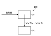
例えば、図2に示されるように、シンチレータ201が発するシンチレーション光を受光できる受光素子202と組み合わせることで、放射線測定装置200としての使用が可能となる。
For example, as shown in FIG. 2, by combining the
以下、本発明の実施例を挙げて具体的に説明するが、本発明はこれらの実施例によって何ら制限されるものではない。また、実施例の中で説明されている特徴の組み合わせ全てが本発明の解決手段に必須のものとは限らない。 The present invention will be specifically explained below with reference to examples, but the present invention is not limited to these examples. Furthermore, not all of the combinations of features described in the examples are necessarily essential to the solution of the present invention.
[実施例]
まず、表1の実施例1~実施例8に示すように、各結晶相の組み合わせにおいて、各組成比になるように評量した。この混合粉末に、総物質量に対してハロゲン化ユーロピウムを1mol%添加した試料を十分に混合した粉末を準備した。また、ハロゲン化リチウムについては、6Li同位体比が95%の原料を用いた。
[Example]
First, the combinations of each crystal phase were weighed to obtain each composition ratio as shown in Examples 1 to 8 in Table 1. A sample in which europium halide was added at 1 mol% relative to the total amount of material was thoroughly mixed with this mixed powder to prepare a powder. For the lithium halide, a raw material with a 6 Li isotope ratio of 95% was used.
次いで、上述した原料の混合物を、内径が6mmの石英管に充填し、真空排気装置を用いて、石英管の内部を2.0×10⁻⁴Pa以下まで真空排気した後、ガスバーナーにより石英管を封入した。 Next, the mixture of the above-mentioned raw materials was filled into a quartz tube having an inner diameter of 6 mm, and the inside of the quartz tube was evacuated to 2.0×10 −4 Pa or less using a vacuum exhaust device, and then the quartz tube was sealed with a gas burner.
次に、加熱ヒーターによって石英管の中の原料混合物を加熱して溶融・固化した。なお、この加熱の後において、融液の温度を降下させる速度、すなわち凝固速度は、20mm/hrとした。この降温の操作により、融液を全て凝固させ、実施例における共晶体を得た。 Next, the raw material mixture in the quartz tube was heated by a heater to melt and solidify. After this heating, the rate at which the temperature of the melt was lowered, i.e., the solidification rate, was 20 mm/hr. Through this temperature-lowering operation, the entire melt was solidified, and the eutectic in the example was obtained.
[比較例]
まず、表1に示す比較例1および比較例2の各結晶相の組み合わせにおいて、各組成比になるように評量した。この混合粉末に、総物質量に対してフッ化ユーロピウムを1mol%添加した試料を十分に混合した粉末を準備した。また、フッ化リチウムについては、6Li同位体比が95%の原料を用いた。
[Comparative Example]
First, the combinations of the crystal phases in Comparative Example 1 and Comparative Example 2 shown in Table 1 were weighed to obtain the respective composition ratios. A powder was prepared by thoroughly mixing this mixed powder with a sample in which 1 mol% of europium fluoride was added to the total substance amount. For lithium fluoride, a raw material with a 6Li isotope ratio of 95% was used.
次いで、作製した原料混合物を、内径が6mmのカーボンルツボに充填し、加熱ヒーターを備える真空チャンバー内に設置した。さらに、真空排気装置を用いて、真空チャンバーの内部を2.0×10⁻⁴Pa以下まで真空排気した後、アルゴンガスを導入した。 The raw material mixture was then filled into a carbon crucible having an inner diameter of 6 mm and placed in a vacuum chamber equipped with a heater. The inside of the vacuum chamber was evacuated to 2.0×10 −4 Pa or less using a vacuum exhaust device, and argon gas was then introduced into the vacuum chamber.
真空チャンバー内のガス置換操作を行った後、加熱ヒーターによって原料混合物を加熱して溶融・固化した。なお、この加熱の後の、融液の温度を降下させる速度、すなわち凝固速度は20mm/hrとした。この降温の操作により、融液を全て凝固させ、比較例の共晶体を得た。 After the gas replacement operation in the vacuum chamber was performed, the raw material mixture was heated by a heater to melt and solidify. After this heating, the rate at which the temperature of the melt was lowered, i.e., the solidification rate, was 20 mm/hr. Through this temperature lowering operation, the entire melt was solidified, and the eutectic of the comparative example was obtained.
次に、実施例1~8および比較例1,比較例2で得られた共晶体を粉砕した粉末について粉末X線回折測定を行い、結晶相を同定した。また、得られた共晶体を、ダイヤモンドワイヤーを備えたワイヤーソーによって0.1mm厚に切断し、切断面を鏡面研磨してウエハとした。得られたウエハについて透過率を測定した。さらに、得られたウエハにX線を照射し、分光器を用いて発光スペクトルを取得し、得られたスペクトルのピーク波長を発光波長とした。 Next, the eutectic bodies obtained in Examples 1 to 8 and Comparative Examples 1 and 2 were crushed into powders, and powder X-ray diffraction measurements were performed to identify the crystal phase. The obtained eutectic bodies were cut into pieces with a thickness of 0.1 mm using a wire saw equipped with a diamond wire, and the cut surfaces were mirror-polished to obtain wafers. The transmittance of the obtained wafers was measured. Furthermore, the obtained wafers were irradiated with X-rays, and an emission spectrum was obtained using a spectroscope, and the peak wavelength of the obtained spectrum was determined as the emission wavelength.
[中性子検出器の作製と特性評価]
当該中性子用シンチレータの中性子に対する応答特性を,次に示す方法によって評価した。まず、光電子増倍管(浜松ホトニクス社製、R7600U)の光電面に、中性子用シンチレータを凝固方向に垂直な面で接着し、中性子検出器(測定器)を製作した。光電子増倍管の光電面に外の光が入射しないよう、中性子検出器を黒色のビニールシート製の遮光材で覆った後に、1MBqの放射能の252Cfからの中性子を、厚さ40mmのポリエチレンブロックからなる中性子減速材を介して減速して照射した。
[Fabrication and Characterization of Neutron Detectors]
The response characteristics of the neutron scintillator to neutrons were evaluated by the following method. First, the neutron scintillator was attached to the photoelectric surface of a photomultiplier tube (R7600U, manufactured by Hamamatsu Photonics) on a surface perpendicular to the solidification direction to fabricate a neutron detector (measurement device). After covering the neutron detector with a light-shielding material made of a black vinyl sheet to prevent external light from entering the photoelectric surface of the photomultiplier tube, neutrons from 252Cf with a radioactivity of 1MBq were moderated and irradiated through a neutron moderator made of a polyethylene block with a thickness of 40mm.
中性子用シンチレータより発せられたシンチレーション光を計測するため、光電子増倍管には、電源供給線より800Vの高電圧を印加し、シンチレーション光を電気信号に変換し、信号出力線より出力した。ここで、光電子増倍管より出力される電気信号は、シンチレーション光を反映したパルス状の信号であり、パルスの波高がシンチレーション光の発光強度を表す。光電子増倍管より出力された電気信号を整形増幅器で整形、増幅した後、多重波高分析器に入力して解析し、波高分布スペクトルを作成し、中性子シンチレータの基準材料であるLi-ガラスと発光量を比較し、発光量を算出した。 To measure the scintillation light emitted by the neutron scintillator, a high voltage of 800V was applied to the photomultiplier tube from the power supply line, and the scintillation light was converted into an electrical signal, which was output from the signal output line. Here, the electrical signal output from the photomultiplier tube was a pulsed signal reflecting the scintillation light, and the pulse height represented the luminous intensity of the scintillation light. The electrical signal output from the photomultiplier tube was shaped and amplified by a shaping amplifier, and then input to a multiple pulse height analyzer for analysis, creating a pulse height distribution spectrum, and the amount of light emitted was compared with that of Li-glass, the reference material for neutron scintillators, to calculate the amount of light emitted.
実施例1~8および比較例1,比較例2で得られた共晶体の評価結果を表1に示す。比較例1,比較例2のシンチレータでは、それぞれの結晶相の屈折率差が0.04以上あるために、透過率が低い。さらに発光量が低いことから、中性子の検出器(測定器)として用いた場合の性能が低下する。一般に、中性子検出器では、1インチ径、1インチ厚を超える大型の中性子シンチレータを用いるため、透過率の低い比較例1、比較例2のシンチレータでは、結晶のサイズ、厚みが大きくなるほど、シンチレータ内の光の減衰が大きくなり、発光量がさらに減少することとなる。 Table 1 shows the evaluation results of the eutectic bodies obtained in Examples 1 to 8 and Comparative Examples 1 and 2. In the scintillators of Comparative Examples 1 and 2, the difference in refractive index between the respective crystal phases is 0.04 or more, so the transmittance is low. Furthermore, the amount of light emitted is low, so performance is reduced when used as a neutron detector (measuring device). Generally, neutron detectors use large neutron scintillators with a diameter of over 1 inch and a thickness of over 1 inch, so in the scintillators of Comparative Examples 1 and 2, which have low transmittance, the larger the crystal size and thickness, the greater the attenuation of light within the scintillator, and the further the amount of light emitted is reduced.
実施例1~8に示す共晶体では、それぞれの結晶相の屈折率差が0.03以下であることから65%以上の透過率を示す。さらに、発光量が1中性子あたり35000光子以上と高く、Liのモル含有率も14%以上と高いため、感度に優れた中性子検出器を実現できる。 The eutectic bodies shown in Examples 1 to 8 have a transmittance of 65% or more because the difference in refractive index between the crystal phases is 0.03 or less. Furthermore, the amount of light emitted is high at 35,000 photons or more per neutron, and the molar content of Li is also high at 14% or more, making it possible to realize a neutron detector with excellent sensitivity.

以上に説明したように、本発明によれば、シンチレータを構成する共晶体の第1結晶相は、Liを含有するものとし、共晶体を構成する複数の結晶相の各々の、互いの屈折率差を0.04以下としたので、高い感度および発光量が得られるシンチレータが提供できるようになる。 As described above, according to the present invention, the first crystal phase of the eutectic that constitutes the scintillator contains Li, and the refractive index difference between each of the multiple crystal phases that constitute the eutectic is set to 0.04 or less, making it possible to provide a scintillator that provides high sensitivity and a high amount of light emission.
なお、本発明は以上に説明した実施の形態に限定されるものではなく、本発明の技術的思想内で、当分野において通常の知識を有する者により、多くの変形および組み合わせが実施可能であることは明白である。 The present invention is not limited to the embodiments described above, and it is clear that many modifications and combinations can be implemented by those with ordinary skill in the art within the technical concept of the present invention.
101…第1結晶相、102…第2結晶相。 101...first crystal phase, 102...second crystal phase.
Claims (3)
前記複数の結晶相の各々は、互いの屈折率差が0.04以下であり、
前記第2結晶相は、発光中心としてPr、Ce、Nd、Sm、Eu、Gd、Tb、Dy、Ho、Dy、Er、Tm、Yb、Tl、Pb、Bi、Ag,Ti,Crのうち少なくとも一種からなる元素を、前記第2結晶相の総物質量に対して0.001mol%以上含有し、
前記第1結晶相は、化学式A x B y X x+2y (0<x<1、0<y≦1)で表されるハロゲン化物を含み、
Aは、Liであり、
BはBe、Mg、Ca、Sr、Baのうち少なくとも一種を含む元素であり、
XはCl、Br、Iのうち少なくとも一種を含む元素である
ことを特徴とするシンチレータ。 The present invention is composed of a eutectic having a plurality of crystalline phases including a first crystalline phase containing Li and a second crystalline phase that emits light when excited by radiation;
The refractive index difference between each of the plurality of crystal phases is 0.04 or less ,
The second crystal phase contains at least one element selected from the group consisting of Pr, Ce, Nd, Sm, Eu, Gd, Tb, Dy, Ho, Dy, Er, Tm, Yb, Tl, Pb, Bi, Ag, Ti, and Cr as a luminescence center in an amount of 0.001 mol% or more with respect to the total amount of substance of the second crystal phase;
The first crystalline phase contains a halide represented by a chemical formula A x B y X x+2y (0<x<1, 0<y≦1),
A is Li;
B is an element including at least one of Be, Mg, Ca, Sr, and Ba;
X is an element containing at least one of Cl , Br and I.
前記複数の結晶相の各々は、互いの屈折率差が0.04以下であり、
前記第2結晶相は、発光中心としてPr、Ce、Nd、Sm、Eu、Gd、Tb、Dy、Ho、Dy、Er、Tm、Yb、Tl、Pb、Bi、Ag,Ti,Crのうち少なくとも一種からなる元素を、前記第2結晶相の総物質量に対して0.001mol%以上含有し、
前記第1結晶相は、化学式LiXで表されるハロゲン化物を含み、XはCl、Br、Iのうち少なくとも一種を含む元素であることを特徴とするシンチレータ。 The present invention is composed of a eutectic having a plurality of crystalline phases including a first crystalline phase containing Li and a second crystalline phase that emits light when excited by radiation;
The refractive index difference between each of the plurality of crystal phases is 0.04 or less,
The second crystal phase contains at least one element selected from the group consisting of Pr, Ce, Nd, Sm, Eu, Gd, Tb, Dy, Ho, Dy, Er, Tm, Yb, Tl, Pb, Bi, Ag, Ti, and Cr as a luminescence center in an amount of 0.001 mol% or more with respect to the total amount of substance of the second crystal phase;
The first crystal phase contains a halide represented by a chemical formula LiX, where X is an element containing at least one of Cl , Br, and I.
前記シンチレータが発するシンチレーション光を受光する受光素子と
を備える放射線測定装置。 A scintillator according to claim 1 or 2 ;
and a light receiving element that receives scintillation light emitted by the scintillator.
Priority Applications (1)
| Application Number | Priority Date | Filing Date | Title |
|---|---|---|---|
| JP2021028343A JP7601330B2 (en) | 2021-02-25 | 2021-02-25 | Scintillator and radiation measuring device |
Applications Claiming Priority (1)
| Application Number | Priority Date | Filing Date | Title |
|---|---|---|---|
| JP2021028343A JP7601330B2 (en) | 2021-02-25 | 2021-02-25 | Scintillator and radiation measuring device |
Publications (2)
| Publication Number | Publication Date |
|---|---|
| JP2022129614A JP2022129614A (en) | 2022-09-06 |
| JP7601330B2 true JP7601330B2 (en) | 2024-12-17 |
Family
ID=83151049
Family Applications (1)
| Application Number | Title | Priority Date | Filing Date |
|---|---|---|---|
| JP2021028343A Active JP7601330B2 (en) | 2021-02-25 | 2021-02-25 | Scintillator and radiation measuring device |
Country Status (1)
| Country | Link |
|---|---|
| JP (1) | JP7601330B2 (en) |
Citations (6)
| Publication number | Priority date | Publication date | Assignee | Title |
|---|---|---|---|---|
| WO2015064588A1 (en) | 2013-10-28 | 2015-05-07 | 株式会社トクヤマ | Neutron scintillator, neutron detector and method for manufacturing neutron scintillator |
| WO2015190444A1 (en) | 2014-06-09 | 2015-12-17 | 株式会社トクヤマ | Neutron scintillator and neutron detector |
| JP2017149883A (en) | 2016-02-26 | 2017-08-31 | 国立大学法人東北大学 | Scintillator and radiation detector |
| JP2018175080A (en) | 2017-04-05 | 2018-11-15 | キヤノン株式会社 | Radiation imaging apparatus, radiation imaging system, control method and program for radiation imaging apparatus |
| JP2019119798A (en) | 2018-01-04 | 2019-07-22 | 国立研究開発法人物質・材料研究機構 | Scintillator material, manufacturing method therefor, x ray radiation detector, and x ray radiation imaging device |
| JP2021025806A (en) | 2019-07-31 | 2021-02-22 | キヤノン株式会社 | Scintillator unit and radiation detector |
-
2021
- 2021-02-25 JP JP2021028343A patent/JP7601330B2/en active Active
Patent Citations (7)
| Publication number | Priority date | Publication date | Assignee | Title |
|---|---|---|---|---|
| WO2015064588A1 (en) | 2013-10-28 | 2015-05-07 | 株式会社トクヤマ | Neutron scintillator, neutron detector and method for manufacturing neutron scintillator |
| WO2015190444A1 (en) | 2014-06-09 | 2015-12-17 | 株式会社トクヤマ | Neutron scintillator and neutron detector |
| US20170052265A1 (en) | 2014-06-09 | 2017-02-23 | Tokuyama Corporation | Neutron scintillator and neutron detector |
| JP2017149883A (en) | 2016-02-26 | 2017-08-31 | 国立大学法人東北大学 | Scintillator and radiation detector |
| JP2018175080A (en) | 2017-04-05 | 2018-11-15 | キヤノン株式会社 | Radiation imaging apparatus, radiation imaging system, control method and program for radiation imaging apparatus |
| JP2019119798A (en) | 2018-01-04 | 2019-07-22 | 国立研究開発法人物質・材料研究機構 | Scintillator material, manufacturing method therefor, x ray radiation detector, and x ray radiation imaging device |
| JP2021025806A (en) | 2019-07-31 | 2021-02-22 | キヤノン株式会社 | Scintillator unit and radiation detector |
Also Published As
| Publication number | Publication date |
|---|---|
| JP2022129614A (en) | 2022-09-06 |
Similar Documents
| Publication | Publication Date | Title |
|---|---|---|
| RU2638158C2 (en) | Scintillator composition, radiation detector device and high-energy radiation recording method | |
| CA2717341C (en) | Metal fluoride lanthanide scintillator | |
| Rutstrom et al. | Improved light yield and growth of large-volume ultrafast single crystal scintillators Cs2ZnCl4 and Cs3ZnCl5 | |
| Yanagida et al. | Phosphors for radiation detectors | |
| WO2013022492A2 (en) | Transparent glass scintillators, methods of making same and devices using same | |
| EP0779254A1 (en) | Photostimulable luminescence glass composition | |
| EP3153562B1 (en) | Neutron scintillator and neutron detector | |
| RU2596765C2 (en) | Scintillator, radiation detector and method for detecting radiation | |
| EP2685286A1 (en) | Neutron beam detection device | |
| US11339326B2 (en) | Tl+-based and mixed halide A3B2X9-type scintillators | |
| Shinozaki et al. | High quantum yield luminescence and scintillation properties of high-Ce-doped MgF2–Al2O3–B2O3 glasses and their glass structure | |
| JP2015111107A (en) | Scintillator and radiation detector | |
| US8933408B2 (en) | Colquiriite-type crystal, scintillator for neutron detection and neutron detector | |
| JP2017149883A (en) | Scintillator and radiation detector | |
| US11474264B2 (en) | Self-assembled directionally solidified eutectics for thermal neutron detection | |
| Leonard et al. | Scintillator glasses | |
| Shah et al. | RbGd/sub 2/Br/sub 7: Ce scintillators for gamma-ray and thermal neutron detection | |
| JP2022129614A (en) | scintillators and radiation measuring devices | |
| Yajima et al. | Tl-Doped CsI/⁶LiBr Scintillator for Thermal Neutron Detection With Ultrahigh Light Yield | |
| EP3447107B1 (en) | Scintillator and preparation method therefor | |
| CN101591537A (en) | Scintillator compositions comprising cerium and praseodymium activator ions and related methods and articles of manufacture | |
| Roos | Scintillation Detectors | |
| Kawaguchi et al. | Inorganic Fluoride Scintillators | |
| JP5737978B2 (en) | Neutron detection scintillator and neutron beam detector | |
| JP5737974B2 (en) | Neutron detection scintillator and neutron beam detector |
Legal Events
| Date | Code | Title | Description |
|---|---|---|---|
| A621 | Written request for application examination |
Free format text: JAPANESE INTERMEDIATE CODE: A621 Effective date: 20240209 |
|
| A977 | Report on retrieval |
Free format text: JAPANESE INTERMEDIATE CODE: A971007 Effective date: 20240729 |
|
| A131 | Notification of reasons for refusal |
Free format text: JAPANESE INTERMEDIATE CODE: A131 Effective date: 20240813 |
|
| A521 | Request for written amendment filed |
Free format text: JAPANESE INTERMEDIATE CODE: A523 Effective date: 20241015 |
|
| TRDD | Decision of grant or rejection written | ||
| A01 | Written decision to grant a patent or to grant a registration (utility model) |
Free format text: JAPANESE INTERMEDIATE CODE: A01 Effective date: 20241105 |
|
| A61 | First payment of annual fees (during grant procedure) |
Free format text: JAPANESE INTERMEDIATE CODE: A61 Effective date: 20241126 |
|
| R150 | Certificate of patent or registration of utility model |
Ref document number: 7601330 Country of ref document: JP Free format text: JAPANESE INTERMEDIATE CODE: R150 |