JP7601845B2 - コネクタ及びその導通検査装置 - Google Patents
コネクタ及びその導通検査装置 Download PDFInfo
- Publication number
- JP7601845B2 JP7601845B2 JP2022179764A JP2022179764A JP7601845B2 JP 7601845 B2 JP7601845 B2 JP 7601845B2 JP 2022179764 A JP2022179764 A JP 2022179764A JP 2022179764 A JP2022179764 A JP 2022179764A JP 7601845 B2 JP7601845 B2 JP 7601845B2
- Authority
- JP
- Japan
- Prior art keywords
- front holder
- connector
- connector housing
- continuity
- fitting
- Prior art date
- Legal status (The legal status is an assumption and is not a legal conclusion. Google has not performed a legal analysis and makes no representation as to the accuracy of the status listed.)
- Active
Links
Images



Classifications
-
- H—ELECTRICITY
- H01—ELECTRIC ELEMENTS
- H01R—ELECTRICALLY-CONDUCTIVE CONNECTIONS; STRUCTURAL ASSOCIATIONS OF A PLURALITY OF MUTUALLY-INSULATED ELECTRICAL CONNECTING ELEMENTS; COUPLING DEVICES; CURRENT COLLECTORS
- H01R13/00—Details of coupling devices of the kinds covered by groups H01R12/70 or H01R24/00 - H01R33/00
- H01R13/40—Securing contact members in or to a base or case; Insulating of contact members
-
- H—ELECTRICITY
- H01—ELECTRIC ELEMENTS
- H01R—ELECTRICALLY-CONDUCTIVE CONNECTIONS; STRUCTURAL ASSOCIATIONS OF A PLURALITY OF MUTUALLY-INSULATED ELECTRICAL CONNECTING ELEMENTS; COUPLING DEVICES; CURRENT COLLECTORS
- H01R13/00—Details of coupling devices of the kinds covered by groups H01R12/70 or H01R24/00 - H01R33/00
- H01R13/64—Means for preventing incorrect coupling
- H01R13/641—Means for preventing incorrect coupling by indicating incorrect coupling; by indicating correct or full engagement
-
- H—ELECTRICITY
- H01—ELECTRIC ELEMENTS
- H01R—ELECTRICALLY-CONDUCTIVE CONNECTIONS; STRUCTURAL ASSOCIATIONS OF A PLURALITY OF MUTUALLY-INSULATED ELECTRICAL CONNECTING ELEMENTS; COUPLING DEVICES; CURRENT COLLECTORS
- H01R13/00—Details of coupling devices of the kinds covered by groups H01R12/70 or H01R24/00 - H01R33/00
- H01R13/46—Bases; Cases
-
- G—PHYSICS
- G01—MEASURING; TESTING
- G01R—MEASURING ELECTRIC VARIABLES; MEASURING MAGNETIC VARIABLES
- G01R31/00—Arrangements for testing electric properties; Arrangements for locating electric faults; Arrangements for electrical testing characterised by what is being tested not provided for elsewhere
- G01R31/50—Testing of electric apparatus, lines, cables or components for short-circuits, continuity, leakage current or incorrect line connections
- G01R31/66—Testing of connections, e.g. of plugs or non-disconnectable joints
- G01R31/68—Testing of releasable connections, e.g. of terminals mounted on a printed circuit board
- G01R31/69—Testing of releasable connections, e.g. of terminals mounted on a printed circuit board of terminals at the end of a cable or a wire harness; of plugs; of sockets, e.g. wall sockets or power sockets in appliances
-
- H—ELECTRICITY
- H01—ELECTRIC ELEMENTS
- H01R—ELECTRICALLY-CONDUCTIVE CONNECTIONS; STRUCTURAL ASSOCIATIONS OF A PLURALITY OF MUTUALLY-INSULATED ELECTRICAL CONNECTING ELEMENTS; COUPLING DEVICES; CURRENT COLLECTORS
- H01R13/00—Details of coupling devices of the kinds covered by groups H01R12/70 or H01R24/00 - H01R33/00
- H01R13/40—Securing contact members in or to a base or case; Insulating of contact members
- H01R13/42—Securing in a demountable manner
- H01R13/436—Securing a plurality of contact members by one locking piece or operation
- H01R13/4364—Insertion of locking piece from the front
-
- H—ELECTRICITY
- H01—ELECTRIC ELEMENTS
- H01R—ELECTRICALLY-CONDUCTIVE CONNECTIONS; STRUCTURAL ASSOCIATIONS OF A PLURALITY OF MUTUALLY-INSULATED ELECTRICAL CONNECTING ELEMENTS; COUPLING DEVICES; CURRENT COLLECTORS
- H01R13/00—Details of coupling devices of the kinds covered by groups H01R12/70 or H01R24/00 - H01R33/00
- H01R13/46—Bases; Cases
- H01R13/502—Bases; Cases composed of different pieces
-
- H—ELECTRICITY
- H01—ELECTRIC ELEMENTS
- H01R—ELECTRICALLY-CONDUCTIVE CONNECTIONS; STRUCTURAL ASSOCIATIONS OF A PLURALITY OF MUTUALLY-INSULATED ELECTRICAL CONNECTING ELEMENTS; COUPLING DEVICES; CURRENT COLLECTORS
- H01R13/00—Details of coupling devices of the kinds covered by groups H01R12/70 or H01R24/00 - H01R33/00
- H01R13/62—Means for facilitating engagement or disengagement of coupling parts or for holding them in engagement
- H01R13/629—Additional means for facilitating engagement or disengagement of coupling parts, e.g. aligning or guiding means, levers, gas pressure electrical locking indicators, manufacturing tolerances
-
- H—ELECTRICITY
- H01—ELECTRIC ELEMENTS
- H01R—ELECTRICALLY-CONDUCTIVE CONNECTIONS; STRUCTURAL ASSOCIATIONS OF A PLURALITY OF MUTUALLY-INSULATED ELECTRICAL CONNECTING ELEMENTS; COUPLING DEVICES; CURRENT COLLECTORS
- H01R13/00—Details of coupling devices of the kinds covered by groups H01R12/70 or H01R24/00 - H01R33/00
- H01R13/62—Means for facilitating engagement or disengagement of coupling parts or for holding them in engagement
- H01R13/639—Additional means for holding or locking coupling parts together, after engagement, e.g. separate keylock, retainer strap
-
- H—ELECTRICITY
- H01—ELECTRIC ELEMENTS
- H01R—ELECTRICALLY-CONDUCTIVE CONNECTIONS; STRUCTURAL ASSOCIATIONS OF A PLURALITY OF MUTUALLY-INSULATED ELECTRICAL CONNECTING ELEMENTS; COUPLING DEVICES; CURRENT COLLECTORS
- H01R13/00—Details of coupling devices of the kinds covered by groups H01R12/70 or H01R24/00 - H01R33/00
- H01R13/62—Means for facilitating engagement or disengagement of coupling parts or for holding them in engagement
- H01R13/627—Snap or like fastening
- H01R13/6271—Latching means integral with the housing
- H01R13/6272—Latching means integral with the housing comprising a single latching arm
-
- H—ELECTRICITY
- H01—ELECTRIC ELEMENTS
- H01R—ELECTRICALLY-CONDUCTIVE CONNECTIONS; STRUCTURAL ASSOCIATIONS OF A PLURALITY OF MUTUALLY-INSULATED ELECTRICAL CONNECTING ELEMENTS; COUPLING DEVICES; CURRENT COLLECTORS
- H01R13/00—Details of coupling devices of the kinds covered by groups H01R12/70 or H01R24/00 - H01R33/00
- H01R13/64—Means for preventing incorrect coupling
- H01R13/645—Means for preventing incorrect coupling by exchangeable elements on case or base
- H01R13/6456—Means for preventing incorrect coupling by exchangeable elements on case or base comprising keying elements at different positions along the periphery of the connector
-
- H—ELECTRICITY
- H01—ELECTRIC ELEMENTS
- H01R—ELECTRICALLY-CONDUCTIVE CONNECTIONS; STRUCTURAL ASSOCIATIONS OF A PLURALITY OF MUTUALLY-INSULATED ELECTRICAL CONNECTING ELEMENTS; COUPLING DEVICES; CURRENT COLLECTORS
- H01R2201/00—Connectors or connections adapted for particular applications
- H01R2201/20—Connectors or connections adapted for particular applications for testing or measuring purposes
Landscapes
- Physics & Mathematics (AREA)
- General Physics & Mathematics (AREA)
- Manufacturing Of Electrical Connectors (AREA)
- Connector Housings Or Holding Contact Members (AREA)
Description
前記コネクタハウジングの周壁には、前端から後方に向けて導通検査装置に対する誤嵌合検知用の溝が形成されており、
前記誤嵌合検知用の溝は、前記フロントホルダ挿入スペースに前記フロントホルダが挿入された際に前記フロントホルダに設けられた突起が嵌まるように構成され、
前記誤嵌合検知用の溝は、前記コネクタハウジングに前記フロントホルダが装着されていない前記コネクタの導通検査を行う導通検査装置の嵌合口に前記フロントホルダが装着されていない前記コネクタハウジングを嵌合した際には、前記嵌合口に設けられた凸部を受け入れることで前記コネクタハウジングの嵌合を可能とし、且つ、前記嵌合口に前記フロントホルダが装着されている前記コネクタハウジングを嵌合した際には、前記溝を塞ぐ前記フロントホルダの前記突起と干渉することで前記コネクタハウジングの嵌合を不可とする、ように構成された、
コネクタ。
検査時に前記コネクタハウジングの嵌合する嵌合口に凸部が設けられており、
前記凸部は、前記フロントホルダが装着されていない前記コネクタハウジングが前記嵌合口に嵌合されるときに前記誤嵌合検知用の溝に受け入れられることで前記コネクタハウジングの嵌合を可能とし、且つ、前記フロントホルダが装着されている前記コネクタハウジングが嵌合されたときに前記溝を塞ぐ前記フロントホルダの前記突起と干渉することで前記コネクタハウジングの嵌合を不可とする、
導通検査装置。
検査時に前記コネクタハウジングの嵌合する嵌合口の奥壁にフロントホルダ検知部が設けられており、
前記フロントホルダ検知部は、前記フロントホルダが装着されている前記コネクタハウジングが前記嵌合口に嵌合されたときに前記フロントホルダが有ることを検知し、且つ、前記フロントホルダが装着されていない前記コネクタハウジングが嵌合されたときに前記フロントホルダが無いことを検知する、
導通検査装置。
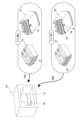
図7に示す導通検査装置40は、コネクタハウジング11にフロントホルダ30が装着されていない場合のフロントホルダ無しコネクタ10専用の導通検査装置である。この導通検査装置40では、検査時にコネクタハウジング11の嵌合する嵌合口41の内底面に凸部46が設けられている。
[1] 端子収容室(12)が設けられたブロック部(13)を有する共に、前記ブロック部(13)に隣接して、端子半挿入検知用のフロントホルダ(30)を前方から挿入するためのフロントホルダ挿入スペース(14)を有するコネクタハウジング(11)を備え、
前記コネクタハウジング(11)の周壁には、前端から後方に向けて導通検査装置(40、50)に対する誤嵌合検知用の溝(16)が形成されており、
前記誤嵌合検知用の溝(16)は、前記フロントホルダ挿入スペース(14)にフロントホルダ(30)が挿入された際に前記フロントホルダ(30)に設けられた突起(36)が嵌まると共に、前記フロントホルダを有さないコネクタ(10)の導通検査装置(40)の嵌合口(41)に当該コネクタハウジング(11)を嵌合した際に前記導通検査装置(40)の嵌合口(41)に設けられた凸部(46)を受け入れる、
コネクタ(10、20)。
検査時に前記コネクタハウジング(11)の嵌合する嵌合口(41)に凸部(46)が設けられており、
前記凸部(46)は、前記フロントホルダを有さないコネクタハウジング(11)が前記嵌合口(41)に嵌合されるときに前記誤嵌合検知用の溝(16)に受け入れられることで前記コネクタハウジング(11)の嵌合を可能とし、且つ、前記フロントホルダ(30)を有するコネクタハウジング(11)が嵌合されたときに前記溝(16)を塞ぐフロントホルダ(30)の突起(36)と干渉することで前記コネクタハウジング(11)の嵌合を不可とする、
導通検査装置(40)。
検査時に前記コネクタハウジング(11)の嵌合する嵌合口(51)の奥壁にフロントホルダ検知部(52)が設けられており、
前記フロントホルダ検知部(52)は、前記フロントホルダ(30)を有するコネクタハウジング(11)が前記嵌合口(51)に嵌合されたときに前記フロントホルダ(30)が有ることを検知し、且つ、前記フロントホルダ(30)を有さないコネクタハウジング(11)が嵌合されたときに前記フロントホルダ(30)が無いことを検知する、
導通検査装置(50)。
11 コネクタハウジング
12 端子収容室
13 ブロック部
14 フロントホルダ挿入スペース
16 誤嵌合検知用の溝
20 フロントホルダ有りコネクタ
30 フロントホルダ
36 突起
40 フロントホルダ無しコネクタ専用の導通検査装置
41 嵌合口
46 凸部
50 フロントホルダ有りコネクタ専用の導通検査装置
51 嵌合口
52 フロントホルダ検知部
Claims (4)
- 端子収容室が設けられたブロック部を有する共に、前記ブロック部に隣接して、端子半挿入検知用のフロントホルダを前方から挿入するためのフロントホルダ挿入スペースを有するコネクタハウジングを備え、前記コネクタハウジングに前記フロントホルダが装着されている状態でも前記フロントホルダが装着されていない状態でも使用可能な、コネクタであって、
前記コネクタハウジングの周壁には、前端から後方に向けて導通検査装置に対する誤嵌合検知用の溝が形成されており、
前記誤嵌合検知用の溝は、前記フロントホルダ挿入スペースに前記フロントホルダが挿入された際に前記フロントホルダに設けられた突起が嵌まるように構成され、
前記誤嵌合検知用の溝は、前記コネクタハウジングに前記フロントホルダが装着されていない前記コネクタの導通検査を行う導通検査装置の嵌合口に前記フロントホルダが装着されていない前記コネクタハウジングを嵌合した際には、前記嵌合口に設けられた凸部を受け入れることで前記コネクタハウジングの嵌合を可能とし、且つ、前記嵌合口に前記フロントホルダが装着されている前記コネクタハウジングを嵌合した際には、前記溝を塞ぐ前記フロントホルダの前記突起と干渉することで前記コネクタハウジングの嵌合を不可とする、ように構成された、
コネクタ。 - 請求項1に記載の、前記コネクタハウジングに前記フロントホルダが装着されていないコネクタ、の導通検査を行う導通検査装置であって、
検査時に前記コネクタハウジングの嵌合する嵌合口に凸部が設けられており、
前記凸部は、前記フロントホルダが装着されていない前記コネクタハウジングが前記嵌合口に嵌合されるときに前記誤嵌合検知用の溝に受け入れられることで前記コネクタハウジングの嵌合を可能とし、且つ、前記フロントホルダが装着されている前記コネクタハウジングが嵌合されたときに前記溝を塞ぐ前記フロントホルダの前記突起と干渉することで前記コネクタハウジングの嵌合を不可とする、
導通検査装置。 - 請求項1に記載の、前記コネクタハウジングに前記フロントホルダが装着されているコネクタ、の導通検査を行う導通検査装置であって、
検査時に前記コネクタハウジングの嵌合する嵌合口の奥壁にフロントホルダ検知部が設けられており、
前記フロントホルダ検知部は、前記フロントホルダが装着されている前記コネクタハウジングが前記嵌合口に嵌合されたときに前記フロントホルダが有ることを検知し、且つ、前記フロントホルダが装着されていない前記コネクタハウジングが嵌合されたときに前記フロントホルダが無いことを検知する、
導通検査装置。 - 請求項1に記載のコネクタと、請求項2に記載の導通検査装置と、請求項3に記載の導通検査装置と、を備えた、コネクタの導通検査システム。
Priority Applications (3)
| Application Number | Priority Date | Filing Date | Title |
|---|---|---|---|
| JP2022179764A JP7601845B2 (ja) | 2022-11-09 | 2022-11-09 | コネクタ及びその導通検査装置 |
| US18/491,728 US12506293B2 (en) | 2022-11-09 | 2023-10-20 | Connector and continuity test device |
| CN202311415603.3A CN118017267A (zh) | 2022-11-09 | 2023-10-26 | 连接器和导通性测试装置 |
Applications Claiming Priority (1)
| Application Number | Priority Date | Filing Date | Title |
|---|---|---|---|
| JP2022179764A JP7601845B2 (ja) | 2022-11-09 | 2022-11-09 | コネクタ及びその導通検査装置 |
Publications (2)
| Publication Number | Publication Date |
|---|---|
| JP2024069012A JP2024069012A (ja) | 2024-05-21 |
| JP7601845B2 true JP7601845B2 (ja) | 2024-12-17 |
Family
ID=90928208
Family Applications (1)
| Application Number | Title | Priority Date | Filing Date |
|---|---|---|---|
| JP2022179764A Active JP7601845B2 (ja) | 2022-11-09 | 2022-11-09 | コネクタ及びその導通検査装置 |
Country Status (3)
| Country | Link |
|---|---|
| US (1) | US12506293B2 (ja) |
| JP (1) | JP7601845B2 (ja) |
| CN (1) | CN118017267A (ja) |
Citations (2)
| Publication number | Priority date | Publication date | Assignee | Title |
|---|---|---|---|---|
| JP2007103177A (ja) | 2005-10-05 | 2007-04-19 | Auto Network Gijutsu Kenkyusho:Kk | シールドコネクタ及びシールドコネクタの製造方法 |
| JP2016103375A (ja) | 2014-11-27 | 2016-06-02 | 矢崎総業株式会社 | カバー、及び、ハウジングとカバーとの接続構造 |
Family Cites Families (14)
| Publication number | Priority date | Publication date | Assignee | Title |
|---|---|---|---|---|
| US4580861A (en) * | 1984-03-30 | 1986-04-08 | Amp Incorporated | Modular connector housing strip |
| JPH0635390Y2 (ja) * | 1989-12-20 | 1994-09-14 | 矢崎総業株式会社 | 端子係止コネクタ |
| JPH0737249Y2 (ja) * | 1990-09-21 | 1995-08-23 | 古河電気工業株式会社 | 雄コネクタ |
| JP2907377B2 (ja) * | 1994-06-03 | 1999-06-21 | 矢崎総業株式会社 | コネクタの結合検知装置 |
| JP3163597B2 (ja) * | 1995-10-12 | 2001-05-08 | 矢崎総業株式会社 | 付属品付コネクタの検査具 |
| JP3099729B2 (ja) * | 1996-04-08 | 2000-10-16 | 住友電装株式会社 | 検査ユニットおよびこれを含むコネクタ検査器 |
| JP3648432B2 (ja) * | 2000-05-25 | 2005-05-18 | 矢崎総業株式会社 | 慣性ロック式コネクタ |
| JP2002343483A (ja) * | 2001-05-11 | 2002-11-29 | Yazaki Corp | ホルダ付きコネクタ |
| US7179135B2 (en) * | 2005-04-25 | 2007-02-20 | J.S. T. Corporation | Electrical connector with a terminal position assurance mechanism |
| JP5635338B2 (ja) * | 2010-08-31 | 2014-12-03 | 矢崎総業株式会社 | コネクタ |
| JP2016004741A (ja) * | 2014-06-19 | 2016-01-12 | 矢崎総業株式会社 | コネクタ |
| US9595789B1 (en) * | 2016-02-10 | 2017-03-14 | I.D. Systems, Inc. | Connector locking mechanism having a sliding connection retention component |
| CN107240800B (zh) * | 2016-03-29 | 2024-03-19 | 泰科电子科技(苏州工业园区)有限公司 | 连接件、连接器、对配连接件、对配连接器及连接组件 |
| JP7424934B2 (ja) | 2020-07-27 | 2024-01-30 | 矢崎総業株式会社 | コネクタ |
-
2022
- 2022-11-09 JP JP2022179764A patent/JP7601845B2/ja active Active
-
2023
- 2023-10-20 US US18/491,728 patent/US12506293B2/en active Active
- 2023-10-26 CN CN202311415603.3A patent/CN118017267A/zh active Pending
Patent Citations (2)
| Publication number | Priority date | Publication date | Assignee | Title |
|---|---|---|---|---|
| JP2007103177A (ja) | 2005-10-05 | 2007-04-19 | Auto Network Gijutsu Kenkyusho:Kk | シールドコネクタ及びシールドコネクタの製造方法 |
| JP2016103375A (ja) | 2014-11-27 | 2016-06-02 | 矢崎総業株式会社 | カバー、及び、ハウジングとカバーとの接続構造 |
Also Published As
| Publication number | Publication date |
|---|---|
| US12506293B2 (en) | 2025-12-23 |
| JP2024069012A (ja) | 2024-05-21 |
| US20240154349A1 (en) | 2024-05-09 |
| CN118017267A (zh) | 2024-05-10 |
Similar Documents
| Publication | Publication Date | Title |
|---|---|---|
| EP2023445B1 (en) | A joint connector and an assembling method therefor | |
| JP5267162B2 (ja) | 防水ジョイントコネクタ | |
| CN101364685B (zh) | 接头连接器及其组装方法 | |
| US20150340790A1 (en) | Joint connector | |
| CN110197969B (zh) | 连接器 | |
| JP4963702B2 (ja) | 端子位置保証装置を有するコネクタ組立体 | |
| EP2363926B1 (en) | Connector assembling jig | |
| CN112600038B (zh) | 连接器 | |
| JP5012326B2 (ja) | ジョイントコネクタ | |
| CN105789976A (zh) | 连接器 | |
| US7438594B2 (en) | Electrical plug-and-socket connector | |
| US6783396B1 (en) | Airtight plug connector and terminal insert | |
| EP1662618B1 (en) | An electrical connector housing, an electrical connector, and a connector assembly. | |
| JP2024069012A (ja) | コネクタ及びその導通検査装置 | |
| JP3433690B2 (ja) | ジョイントコネクタ | |
| JP5056404B2 (ja) | コネクタ | |
| JP4420278B2 (ja) | 整合安定化機構及び電気コネクタ組立体を安定して整合させる方法 | |
| JP2008130561A (ja) | 電気コネクタ | |
| JP7453067B2 (ja) | コネクタセット | |
| CN116368694A (zh) | 连接器 | |
| JP2004119088A (ja) | 電気コネクタ | |
| JP4367313B2 (ja) | コネクタ | |
| JP2005108498A (ja) | コネクタの半嵌合検知構造 | |
| JPH09147988A (ja) | 半嵌合検知機能付きコネクタ | |
| JP4089604B2 (ja) | コネクタ |
Legal Events
| Date | Code | Title | Description |
|---|---|---|---|
| A621 | Written request for application examination |
Free format text: JAPANESE INTERMEDIATE CODE: A621 Effective date: 20240315 |
|
| A977 | Report on retrieval |
Free format text: JAPANESE INTERMEDIATE CODE: A971007 Effective date: 20240927 |
|
| A131 | Notification of reasons for refusal |
Free format text: JAPANESE INTERMEDIATE CODE: A131 Effective date: 20241001 |
|
| A521 | Request for written amendment filed |
Free format text: JAPANESE INTERMEDIATE CODE: A523 Effective date: 20241030 |
|
| TRDD | Decision of grant or rejection written | ||
| A01 | Written decision to grant a patent or to grant a registration (utility model) |
Free format text: JAPANESE INTERMEDIATE CODE: A01 Effective date: 20241203 |
|
| A61 | First payment of annual fees (during grant procedure) |
Free format text: JAPANESE INTERMEDIATE CODE: A61 Effective date: 20241205 |
|
| R150 | Certificate of patent or registration of utility model |
Ref document number: 7601845 Country of ref document: JP Free format text: JAPANESE INTERMEDIATE CODE: R150 |