JP7610532B2 - Cooking equipment - Google Patents

Cooking equipment Download PDF

Info

Publication number
JP7610532B2
JP7610532B2 JP2021570082A JP2021570082A JP7610532B2 JP 7610532 B2 JP7610532 B2 JP 7610532B2 JP 2021570082 A JP2021570082 A JP 2021570082A JP 2021570082 A JP2021570082 A JP 2021570082A JP 7610532 B2 JP7610532 B2 JP 7610532B2
Authority
JP
Japan
Prior art keywords
heat
glass
space
glass plate
air
Prior art date
Legal status (The legal status is an assumption and is not a legal conclusion. Google has not performed a legal analysis and makes no representation as to the accuracy of the status listed.)
Active
Application number
JP2021570082A
Other languages
Japanese (ja)
Other versions
JPWO2021141080A1 (en
Inventor
雅之 岩本
伸二 浅海
浩己 末永
正浩 西島
智宏 北浦
佑 篠原
剛 大谷
Current Assignee (The listed assignees may be inaccurate. Google has not performed a legal analysis and makes no representation or warranty as to the accuracy of the list.)
Sharp Corp
Original Assignee
Sharp Corp
Priority date (The priority date is an assumption and is not a legal conclusion. Google has not performed a legal analysis and makes no representation as to the accuracy of the date listed.)
Filing date
Publication date
Application filed by Sharp Corp filed Critical Sharp Corp
Publication of JPWO2021141080A1 publication Critical patent/JPWO2021141080A1/ja
Application granted granted Critical
Publication of JP7610532B2 publication Critical patent/JP7610532B2/en
Active legal-status Critical Current
Anticipated expiration legal-status Critical

Links

Images

Classifications

    • FMECHANICAL ENGINEERING; LIGHTING; HEATING; WEAPONS; BLASTING
    • F24HEATING; RANGES; VENTILATING
    • F24CDOMESTIC STOVES OR RANGES ; DETAILS OF DOMESTIC STOVES OR RANGES, OF GENERAL APPLICATION
    • F24C15/00Details
    • F24C15/02Doors specially adapted for stoves or ranges
    • F24C15/04Doors specially adapted for stoves or ranges with transparent panels
    • FMECHANICAL ENGINEERING; LIGHTING; HEATING; WEAPONS; BLASTING
    • F24HEATING; RANGES; VENTILATING
    • F24CDOMESTIC STOVES OR RANGES ; DETAILS OF DOMESTIC STOVES OR RANGES, OF GENERAL APPLICATION
    • F24C15/00Details
    • F24C15/006Arrangements for circulation of cooling air
    • FMECHANICAL ENGINEERING; LIGHTING; HEATING; WEAPONS; BLASTING
    • F24HEATING; RANGES; VENTILATING
    • F24CDOMESTIC STOVES OR RANGES ; DETAILS OF DOMESTIC STOVES OR RANGES, OF GENERAL APPLICATION
    • F24C15/00Details
    • F24C15/16Shelves, racks or trays inside ovens; Supports therefor
    • F24C15/162Co-operating with a door, e.g. operated by the door
    • FMECHANICAL ENGINEERING; LIGHTING; HEATING; WEAPONS; BLASTING
    • F24HEATING; RANGES; VENTILATING
    • F24CDOMESTIC STOVES OR RANGES ; DETAILS OF DOMESTIC STOVES OR RANGES, OF GENERAL APPLICATION
    • F24C15/00Details
    • F24C15/34Elements and arrangements for heat storage or insulation
    • HELECTRICITY
    • H05ELECTRIC TECHNIQUES NOT OTHERWISE PROVIDED FOR
    • H05BELECTRIC HEATING; ELECTRIC LIGHT SOURCES NOT OTHERWISE PROVIDED FOR; CIRCUIT ARRANGEMENTS FOR ELECTRIC LIGHT SOURCES, IN GENERAL
    • H05B6/00Heating by electric, magnetic or electromagnetic fields
    • H05B6/64Heating using microwaves
    • H05B6/6414Aspects relating to the door of the microwave heating apparatus

Landscapes

  • Engineering & Computer Science (AREA)
  • Chemical & Material Sciences (AREA)
  • Combustion & Propulsion (AREA)
  • Mechanical Engineering (AREA)
  • General Engineering & Computer Science (AREA)
  • Physics & Mathematics (AREA)
  • Electromagnetism (AREA)
  • Electric Ovens (AREA)

Description

本発明は、加熱調理器に関する。 The present invention relates to a cooking appliance.

加熱調理器が知られている。加熱調理器は、加熱調理室と、引出し体とを備える。加熱調理室は、収容空間を有する。引出し体は、開閉扉と一体化されている。開閉扉は、収容空間を閉塞可能である。引出し体は、加熱調理室に対して引出し可能に設置される。このような加熱調理器は、システムキッチンのキャビネットに組み込まれている。 A cooking appliance is known. The cooking appliance comprises a cooking chamber and a drawer body. The cooking chamber has a storage space. The drawer body is integrated with an opening/closing door. The opening/closing door is capable of closing the storage space. The drawer body is installed so that it can be pulled out from the cooking chamber. Such a cooking appliance is incorporated into a cabinet of a system kitchen.

特許文献1には、加熱調理器が開示されている。特許文献1に開示の加熱調理器の加熱機能は、マイクロ波加熱機能と、高速熱風加熱機能とからなる。マイクロ波加熱機能は、被加熱物に向かってマイクロ波を照射する機能である。高速熱風加熱機能は、被加熱物に向かって熱風を高速で吹き出す機能である。 Patent Document 1 discloses a cooking device. The heating functions of the cooking device disclosed in Patent Document 1 consist of a microwave heating function and a high-speed hot air heating function. The microwave heating function is a function of irradiating microwaves towards an object to be heated. The high-speed hot air heating function is a function of blowing hot air at high speed towards the object to be heated.

特開2010-133634号公報JP 2010-133634 A

しかしながら、特許文献1に開示の加熱調理器では、高速熱風加熱機能を使用する場合、加熱調理室内の温度の上昇に伴い、開閉扉(蓋部)の表面の温度(外面温度)が上昇するおそれがある。However, in the cooking device disclosed in Patent Document 1, when the high-speed hot air heating function is used, there is a risk that the surface temperature (external surface temperature) of the opening and closing door (lid) will rise as the temperature inside the cooking chamber rises.

本発明は、上記課題に鑑み、蓋部の外面温度の上昇を低減することができる加熱調理器を提供することを目的とする。In view of the above problems, the present invention aims to provide a cooking device that can reduce the rise in the outer surface temperature of the lid.

本発明の加熱調理器は、加熱調理室と、蓋部と、熱供給部とを備える。前記加熱調理室は、収容空間と、開口とを有する。前記収容空間には、被加熱物が収容される。前記開口は、前記収容空間と連通する。前記蓋部は、前記開口を閉塞可能にする。前記熱供給部は、熱を前記収容空間内に供給する。前記蓋部は、透視窓部を有する。前記透視窓部は、前記収容空間内を視認可能にする。前記透視窓部は、少なくとも3枚のガラス板を有する。前記少なくとも3枚のガラス板は、熱線反射ガラスと、第1ガラス板と、第2ガラス板とを含む。前記熱線反射ガラスは、熱線を反射する。前記第1ガラス板は、前記収容空間側に位置する。前記第2ガラス板は、前記収容空間側とは反対側に位置する。前記熱線反射ガラスは、前記第1ガラス板と前記第2ガラス板との間に位置する。前記第1ガラス板と、前記熱線反射ガラスと、前記第2ガラス板とは、間隔を空けて並設されている。The cooking device of the present invention comprises a cooking chamber, a lid, and a heat supply unit. The cooking chamber has a storage space and an opening. The storage space contains an object to be heated. The opening communicates with the storage space. The lid allows the opening to be closed. The heat supply unit supplies heat into the storage space. The lid has a see-through window. The see-through window allows the storage space to be viewed. The see-through window has at least three glass plates. The at least three glass plates include a heat ray reflecting glass, a first glass plate, and a second glass plate. The heat ray reflecting glass reflects heat rays. The first glass plate is located on the storage space side. The second glass plate is located on the opposite side to the storage space side. The heat ray reflecting glass is located between the first glass plate and the second glass plate. The first glass plate, the heat ray reflecting glass plate, and the second glass plate are arranged in parallel with each other with a gap therebetween.

本発明の加熱調理器によれば、蓋部の外面温度の上昇を低減することができる。 According to the cooking device of the present invention, the increase in the outer surface temperature of the lid can be reduced.

本発明の実施形態に係る加熱調理器の斜視図である。1 is a perspective view of a cooking device according to an embodiment of the present invention; 本発明の実施形態に係る加熱調理器の斜視図である。1 is a perspective view of a cooking device according to an embodiment of the present invention; 本発明の実施形態に係る加熱調理器の右側面を示す図である。FIG. 2 is a diagram showing a right side view of the cooking device according to the embodiment of the present invention. 本発明の実施形態に係る加熱調理器の左側面を示す図である。FIG. 2 is a diagram showing the left side of the cooking device according to the embodiment of the present invention. 本発明の実施形態に係る加熱調理器の正面図である。FIG. 1 is a front view of a cooking device according to an embodiment of the present invention. 本発明の実施形態に係る加熱調理器の正面図である。FIG. 1 is a front view of a cooking device according to an embodiment of the present invention. 図1の切断線VIIで切断した加熱調理器の断面図である。FIG. 7 is a cross-sectional view of the cooking device taken along line VII in FIG. 1 . 図1の切断線VIIIで切断した加熱調理器の断面図である。FIG. 8 is a cross-sectional view of the cooking device taken along line VIII in FIG. 1 . 本発明の実施形態に係る加熱調理器の斜視図である。1 is a perspective view of a cooking device according to an embodiment of the present invention; 本発明の実施形態に係る加熱調理器の斜視図である。1 is a perspective view of a cooking device according to an embodiment of the present invention; 本発明の実施形態に係る加熱調理器の構成を示すブロック図である。1 is a block diagram showing a configuration of a cooking device according to an embodiment of the present invention. 図1の切断線XIIで切断した引出し体の蓋部の断面図である。1. FIG. 1 is a cross-sectional view of the cover of the drawer body taken along line XII in FIG. 本発明の実施形態に係る加熱調理器の外観を示す斜視図である。1 is a perspective view showing an appearance of a cooking device according to an embodiment of the present invention; 本発明の実施形態に係る加熱調理器の外観を示す斜視図である。1 is a perspective view showing an appearance of a cooking device according to an embodiment of the present invention; 図14の切断線XVで切断した蓋部20の部分断面図である。15 is a partial cross-sectional view of the lid portion 20 taken along the cutting line XV in FIG. 14 . 本発明の実施形態に係る加熱調理器の右側面を示す図である。FIG. 2 is a diagram showing a right side view of the cooking device according to the embodiment of the present invention. 本発明の実施形態に係る加熱調理器の裏面を示す図である。FIG. 2 is a diagram showing the rear surface of the cooking device according to the embodiment of the present invention. 本発明の実施形態に係る加熱調理器の上面を示す図である。FIG. 2 is a diagram showing a top view of the cooking device according to the embodiment of the present invention. 本発明の実施形態に係る加熱調理器の左側面を示す図である。FIG. 2 is a diagram showing the left side of the cooking device according to the embodiment of the present invention. 本発明の実施形態に係る加熱調理器がビルトインされるキャビネットの外観を示す図である。FIG. 2 is a diagram showing the external appearance of a cabinet in which a cooking device according to an embodiment of the present invention is built.

以下、図面を参照して、本発明に係る加熱調理器の実施形態について説明する。なお、図中、同一又は相当部分については同一の参照符号を付して説明を繰り返さない。Hereinafter, an embodiment of the cooking device according to the present invention will be described with reference to the drawings. Note that in the drawings, the same or corresponding parts are designated by the same reference symbols and the description will not be repeated.

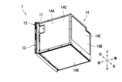
図1及び図2を参照して、本実施形態に係る加熱調理器1について説明する。図1及び図2は、本実施形態に係る加熱調理器1の斜視図である。詳しくは、図1は、右斜め前の上方から観た加熱調理器1を示す。図2は、右斜め後の下方から観た加熱調理器1を示す。The cooking device 1 according to this embodiment will be described with reference to Figures 1 and 2. Figures 1 and 2 are perspective views of the cooking device 1 according to this embodiment. In detail, Figure 1 shows the cooking device 1 as viewed from above, diagonally to the right and front. Figure 2 shows the cooking device 1 as viewed from below, diagonally to the right and rear.

加熱調理器1は、被加熱物を加熱調理する。被加熱物は、例えば、食品である。図1に示すように、加熱調理器1は、加熱調理室10と、操作パネル部12と、引出し体13と、筐体14とを備える。The cooking device 1 cooks an object to be heated. The object to be heated is, for example, food. As shown in FIG. 1, the cooking device 1 includes a cooking chamber 10, an operation panel unit 12, a drawer body 13, and a housing 14.

本実施形態では、加熱調理器1の操作パネル部12が配置される側を前側とし、その反対側を後側と規定する。また、加熱調理器1を前側から見たときの右側を右側とし、その反対側を左側と規定する。また、加熱調理器1の前後方向及び左右方向と直交する方向において、操作パネル部12が配置される側を上側とし、その反対側を下側と規定する。なお、これらの向きは、本発明の加熱調理器の使用時の向きを限定するものではない。In this embodiment, the side on which the operation panel unit 12 of the cooking appliance 1 is arranged is defined as the front side, and the opposite side is defined as the rear side. In addition, the right side when the cooking appliance 1 is viewed from the front side is defined as the right side, and the opposite side is defined as the left side. In addition, in the direction perpendicular to the front-to-rear and left-to-right directions of the cooking appliance 1, the side on which the operation panel unit 12 is arranged is defined as the upper side, and the opposite side is defined as the lower side. Note that these orientations do not limit the orientation of the cooking appliance of the present invention when in use.

加熱調理室10は、箱状である。加熱調理室10は、収容空間1Aを内部に有する。収容空間1Aには、被加熱物が収容される。The cooking chamber 10 is box-shaped. The cooking chamber 10 has a storage space 1A inside. The object to be heated is stored in the storage space 1A.

本実施形態では、加熱調理器1は、加熱調理モードとして、レンジ加熱モード、第1熱風循環加熱モード、第2熱風循環加熱モード、及びグリル加熱モードを有する。レンジ加熱モードは、主として、収容空間1A内にマイクロ波を放射することによって、被加熱物を加熱調理するモードである。第1熱風循環加熱モードは、主として、収容空間1A内に第1熱風H1を循環させて、被加熱物を加熱調理するモードである。第2熱風循環加熱モードは、主として、第1モード及び第2モードを含む。第1モードは、第2熱風H2を被加熱物の上面に直接吹き付けることによって、被加熱物を加熱調理するモードである。第2モードは、収容空間1A内に第2熱風H2を循環させて、収容空間1A内を短時間で予熱するモードである。グリル加熱モードは、主として、熱放射に曝すことによって、被加熱物を加熱調理するモードである。In this embodiment, the cooking device 1 has a range heating mode, a first hot air circulation heating mode, a second hot air circulation heating mode, and a grill heating mode as cooking modes. The range heating mode is a mode in which the object to be heated is cooked by mainly radiating microwaves into the storage space 1A. The first hot air circulation heating mode is a mode in which the object to be heated is cooked by mainly circulating the first hot air H1 into the storage space 1A. The second hot air circulation heating mode mainly includes the first mode and the second mode. The first mode is a mode in which the object to be heated is cooked by directly blowing the second hot air H2 onto the upper surface of the object to be heated. The second mode is a mode in which the second hot air H2 is circulated into the storage space 1A to preheat the storage space 1A in a short time. The grill heating mode is a mode in which the object to be heated is cooked by mainly exposing it to thermal radiation.

加熱調理室10は、パネル11を有する。パネル11は、加熱調理室10の前側に配置されている。パネル11は、開口11Aを有する。開口11Aは、パネル11の略中央部に位置する。開口11Aは矩形状である。開口11Aは、収容空間1Aと連通している。パネル11の詳細については、図6を参照して後述する。The cooking chamber 10 has a panel 11. The panel 11 is disposed at the front side of the cooking chamber 10. The panel 11 has an opening 11A. The opening 11A is located approximately in the center of the panel 11. The opening 11A is rectangular. The opening 11A is in communication with the storage space 1A. Details of the panel 11 will be described later with reference to FIG. 6.

操作パネル部12は、ユーザーからの操作を受け付ける。操作パネル部12は、パネル11より前側に配置されている。つまり、操作パネル部12は、加熱調理室10の前側に配置されている。操作パネル部12は、加熱調理器1の上部に位置する。The operation panel unit 12 accepts operations from the user. The operation panel unit 12 is arranged in front of the panel 11. In other words, the operation panel unit 12 is arranged in front of the heating cooking chamber 10. The operation panel unit 12 is located at the top of the heating cooker 1.

引出し体13は、収容空間1Aに対して引出し方向に引出し自在である。詳しくは、引出し体13は、加熱調理室10の前側に引き出される。引出し体13は、操作パネル部12の下側に位置する。引出し体13の構成の詳細については、図3及び図4を参照して後述する。引出し方向は、前後方向と略平行である。The drawer body 13 can be freely pulled out in a pull-out direction relative to the storage space 1A. More specifically, the drawer body 13 is pulled out to the front side of the cooking chamber 10. The drawer body 13 is located below the operation panel unit 12. Details of the configuration of the drawer body 13 will be described later with reference to Figures 3 and 4. The pull-out direction is approximately parallel to the front-rear direction.

筐体14は、加熱調理室10を収容する。筐体14は、前側が開口した直方体状物である。図2に示すように、筐体14は、右壁14A、左壁14B、上壁14C、下壁14D及び後壁14Eを有する。The housing 14 houses the cooking chamber 10. The housing 14 is a rectangular parallelepiped with an open front. As shown in Figure 2, the housing 14 has a right wall 14A, a left wall 14B, an upper wall 14C, a lower wall 14D, and a rear wall 14E.

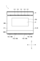
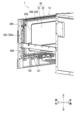
次に、図1~図5を参照して、引出し体13について更に説明する。図3は、本実施形態に係る加熱調理器1の右側面を示す図である。詳しくは、図3は、筐体14が取り外された状態の加熱調理器1の右側面を示す。図4は、本実施形態に係る加熱調理器1の左側面を示す図である。詳しくは、図4は、筐体14が取り外された状態の加熱調理器1の左側面を示す。図5は、本実施形態に係る加熱調理器1の正面図である。Next, the drawer body 13 will be further described with reference to Figures 1 to 5. Figure 3 is a diagram showing the right side of the cooking device 1 according to this embodiment. Specifically, Figure 3 shows the right side of the cooking device 1 with the housing 14 removed. Figure 4 is a diagram showing the left side of the cooking device 1 according to this embodiment. Specifically, Figure 4 shows the left side of the cooking device 1 with the housing 14 removed. Figure 5 is a front view of the cooking device 1 according to this embodiment.

図3及び図4に示すように、引出し体13は、蓋部20と、載置部131と、左右一対のスライド部材132と、支持部材133とを有する。As shown in Figures 3 and 4, the drawer body 13 has a lid portion 20, a mounting portion 131, a pair of left and right slide members 132, and a support member 133.

蓋部20は、パネル11の開口11A(図1参照)を閉塞可能である。図5に示すように、蓋部20は、略矩形の板状部材である。蓋部20は、透視窓部21を有する。透視窓部21は、左右方向及び上下方向において、蓋部20の略中央部に位置する。透視窓部21は、加熱調理室10内の収容空間1A(図1参照)を視認可能にする。透視窓部21の構成については、図12を参照して後述する。蓋部20の構成の詳細については、図13~図15を参照して説明する。The lid portion 20 is capable of closing the opening 11A (see FIG. 1) of the panel 11. As shown in FIG. 5, the lid portion 20 is a substantially rectangular plate-shaped member. The lid portion 20 has a see-through window portion 21. The see-through window portion 21 is located substantially in the center of the lid portion 20 in the left-right and up-down directions. The see-through window portion 21 allows the storage space 1A (see FIG. 1) within the cooking chamber 10 to be viewed. The configuration of the see-through window portion 21 will be described later with reference to FIG. 12. Details of the configuration of the lid portion 20 will be described with reference to FIGS. 13 to 15.

図3及び図4に示すように、載置部131は、被加熱物を載置可能である。蓋部20は、後面20Aを有する。蓋部20の後面20Aは、パネル11の開口11A(図1参照)と対向する。載置部131は、蓋部20の後面20Aに取り付けられている。3 and 4, the placement portion 131 is capable of placing an object to be heated. The lid portion 20 has a rear surface 20A. The rear surface 20A of the lid portion 20 faces the opening 11A of the panel 11 (see FIG. 1). The placement portion 131 is attached to the rear surface 20A of the lid portion 20.

左右一対のスライド部材132は、蓋部20を支持する。左右一対のスライド部材132は、蓋部20を支持することにより、載置部131を支持する。左右一対のスライド部材132は、蓋部20の後面20Aに取り付けられている。左右一対のスライド部材132は、右側スライド部材132a(図3参照)と、左側スライド部材132b(図4参照)とを有する。右側スライド部材132a(図3参照)及び左側スライド部材132b(図4参照)の各々は、前後方向を長手方向とする。The pair of left and right slide members 132 support the lid portion 20. The pair of left and right slide members 132 support the lid portion 20, thereby supporting the placement portion 131. The pair of left and right slide members 132 are attached to the rear surface 20A of the lid portion 20. The pair of left and right slide members 132 include a right slide member 132a (see FIG. 3) and a left slide member 132b (see FIG. 4). The right slide member 132a (see FIG. 3) and the left slide member 132b (see FIG. 4) each have a longitudinal direction in the front-to-rear direction.

支持部材133は、蓋部20を支持する。支持部材133は、蓋部20を支持することにより、載置部131を支持する。支持部材133は、蓋部20の後面20Aの左右方向の略中央部で、かつ載置部131よりも下側に取り付けられている。支持部材133は、前後方向を長手方向とする板状部材である。 The support member 133 supports the lid portion 20. The support member 133 supports the lid portion 20, and thereby supports the mounting portion 131. The support member 133 is attached to the rear surface 20A of the lid portion 20 at approximately the center in the left-right direction, below the mounting portion 131. The support member 133 is a plate-shaped member whose longitudinal direction is the front-rear direction.

支持部材133は、ラック部を有する。ラック部は複数の歯を有する。加熱調理器1は、図11を参照して後述する駆動機構36を有する。駆動機構36は、図8を参照して後述する吸気空間AR内に収納されている。駆動機構36は、支持部材133のラック部と噛み合うことで、引出し体13を開状態又は閉状態にする。引出し体13の開状態とは、引出し体13の載置部131が収容空間1A内から引き出された状態を示す。引出し体13の閉状態とは、引出し体13の載置部131が収容空間1A内に引き込まれた状態を示す。The support member 133 has a rack portion. The rack portion has a number of teeth. The cooking appliance 1 has a drive mechanism 36, which will be described later with reference to Figure 11. The drive mechanism 36 is housed in the intake space AR, which will be described later with reference to Figure 8. The drive mechanism 36 opens or closes the drawer body 13 by engaging with the rack portion of the support member 133. The open state of the drawer body 13 refers to a state in which the mounting portion 131 of the drawer body 13 is pulled out from within the storage space 1A. The closed state of the drawer body 13 refers to a state in which the mounting portion 131 of the drawer body 13 is pulled into the storage space 1A.

次に、図1~図6を参照して、パネル11について更に説明する。図6は、本実施形態に係る加熱調理器1の正面図である。詳しくは、図6は、引出し体13が取り外された状態の加熱調理器1を示す。Next, the panel 11 will be further described with reference to Figures 1 to 6. Figure 6 is a front view of the cooking device 1 according to this embodiment. In particular, Figure 6 shows the cooking device 1 with the drawer body 13 removed.

図6に示すように、パネル11は、矩形状の板状部材である。パネル11は、開口11Aに加えて、複数の第1貫通孔部11Bと、複数の第2貫通孔部11Cと、一対の第3貫通孔部11Dと、第4貫通孔部11Eと、一対の第5貫通孔部11Fとを有する。以下、複数の第2貫通孔部11Cをまとめて「排気孔部11C」と記載する。As shown in Figure 6, the panel 11 is a rectangular plate-like member. In addition to the opening 11A, the panel 11 has a plurality of first through hole portions 11B, a plurality of second through hole portions 11C, a pair of third through hole portions 11D, a fourth through hole portion 11E, and a pair of fifth through hole portions 11F. Hereinafter, the plurality of second through hole portions 11C will be collectively referred to as "exhaust hole portions 11C."

複数の第1貫通孔部11Bは、パネル11の開口11Aより下側部分に位置する。複数の第1貫通孔部11Bは、4つの列を形成する。本実施形態では、4つの列の各々は、6つ又は7つの第1貫通孔部11Bが上下方向に沿って一列に配置されてなる。4つの列のうちの2列は、パネル11の右側部分に位置する。4列のうちの残りの2列は、パネル11の左側部分に位置する。以下、4列のうち最も左側に位置する列を除いた各列を構成する7つの第1貫通孔部11Bをまとめて「吸気孔部11BA」と記載する場合がある。以下、4列のうち最も左側に位置する列を構成する6つの第1貫通孔部11Bをまとめて「排気孔部11BB」と記載する場合がある。各吸気孔部11BAは、図7及び図8を参照して後述する空間Rと、加熱調理器1の外部とを連通する。各吸気孔部11BAは、図9~図11を参照して後述する冷却用ファン40が吹き出す吹出気流BFに対して上流に位置する。The multiple first through-holes 11B are located in a lower portion of the opening 11A of the panel 11. The multiple first through-holes 11B form four rows. In this embodiment, each of the four rows is composed of six or seven first through-holes 11B arranged in a row along the vertical direction. Two of the four rows are located on the right side of the panel 11. The remaining two of the four rows are located on the left side of the panel 11. Hereinafter, the seven first through-holes 11B constituting each row except the row located on the left side of the four rows may be collectively referred to as the "intake hole section 11BA". Hereinafter, the six first through-holes 11B constituting the row located on the left side of the four rows may be collectively referred to as the "exhaust hole section 11BB". Each intake hole section 11BA communicates with the space R described later with reference to Figures 7 and 8 and the outside of the cooking appliance 1. Each of the air intake holes 11BA is located upstream of an airflow BF blown out by a cooling fan 40, which will be described later with reference to FIGS.

排気孔部11Cは、図7及び図8を参照して後述する空間Rと、加熱調理器1の外部とを連通する。排気孔部11Cは、図9~図11を参照して後述する冷却用ファン40が吹き出す吹出気流BFに対して下流に位置する。また、排気孔部11Cは、パネル11の開口11Aより上側部分に位置する。複数の第2貫通孔部11Cは、パネル11の右部から左部に渡って一列に配置されている。また、図5に示すように、排気孔部11Cは、上下方向において、引出し体13(図1参照)と操作パネル部12との間に位置する。The exhaust hole portion 11C communicates between the space R, which will be described later with reference to Figures 7 and 8, and the outside of the cooking appliance 1. The exhaust hole portion 11C is located downstream of the outlet airflow BF blown out by the cooling fan 40, which will be described later with reference to Figures 9 to 11. The exhaust hole portion 11C is located above the opening 11A of the panel 11. The multiple second through-hole portions 11C are arranged in a row from the right to the left of the panel 11. As shown in Figure 5, the exhaust hole portion 11C is located between the drawer body 13 (see Figure 1) and the operation panel portion 12 in the vertical direction.

図6に示すように、一対の第3貫通孔部11Dは、右側第3貫通孔部11Daと、左側第3貫通孔部11Dbとを有する。右側第3貫通孔部11Daは、パネル11の開口11Aより右側部分に位置する。左側第3貫通孔部11Dbは、パネル11の開口11Aより左側部分に位置する。図3及び図4を参照して説明した右側スライド部材132aは、パネル11の右側第3貫通孔部11Daを貫通する。図3及び図4を参照して説明した左側スライド部材132bは、パネル11の左側第3貫通孔部11Dbを貫通する。As shown in Figure 6, the pair of third through hole portions 11D have a right third through hole portion 11Da and a left third through hole portion 11Db. The right third through hole portion 11Da is located to the right of the opening 11A of the panel 11. The left third through hole portion 11Db is located to the left of the opening 11A of the panel 11. The right slide member 132a described with reference to Figures 3 and 4 passes through the right third through hole portion 11Da of the panel 11. The left slide member 132b described with reference to Figures 3 and 4 passes through the left third through hole portion 11Db of the panel 11.

第4貫通孔部11Eは、パネル11の開口11Aより下側部分で、かつ左右方向の略中央部に位置する。図3及び図4を参照して説明した支持部材133は、パネル11の第4貫通孔部11Eを貫通する。The fourth through hole portion 11E is located below the opening 11A of the panel 11 and approximately in the center in the left-right direction. The support member 133 described with reference to Figures 3 and 4 penetrates the fourth through hole portion 11E of the panel 11.

一対の第5貫通孔部11Fは、右側第5貫通孔部11Faと、左側第5貫通孔部11Fbとを有する。右側第5貫通孔部11Faは、引出し体13の閉状態において、図14を参照して後述する右側給気孔部23Aaと対向する。詳しくは、右側第5貫通孔部11Faは、パネル11の開口11Aより右側部分で、かつ右側第3貫通孔部11Daよりも上側部分に位置する。左側第5貫通孔部11Fbは、引出し体13の閉状態において、図14を参照して後述する左側給気孔部23Abと対向する。詳しくは、左側第5貫通孔部11Fbは、パネル11の開口11Aより左側部分で、かつ左側第3貫通孔部11Dbよりも上側部分に位置する。引出し体13の閉状態は、図3及び図4を参照して説明した蓋部20が開口11Aを閉塞する状態を含む。The pair of fifth through-holes 11F includes a right fifth through-hole 11Fa and a left fifth through-hole 11Fb. When the drawer body 13 is in the closed state, the right fifth through-hole 11Fa faces the right air supply hole 23Aa, which will be described later with reference to FIG. 14. More specifically, the right fifth through-hole 11Fa is located to the right of the opening 11A of the panel 11 and above the right third through-hole 11Da. When the drawer body 13 is in the closed state, the left fifth through-hole 11Fb faces the left air supply hole 23Ab, which will be described later with reference to FIG. 14. More specifically, the left fifth through-hole 11Fb is located to the left of the opening 11A of the panel 11 and above the left third through-hole 11Db. The closed state of the drawer body 13 includes the state in which the cover 20 described with reference to FIGS. 3 and 4 closes the opening 11A.

次に、図1~図6を参照して、加熱調理器1の構成について更に説明する。Next, the configuration of the cooking device 1 will be further explained with reference to Figures 1 to 6.

図3及び図4に示すように、加熱調理器1は、左右一対の連結部15と、左右一対のスライドレール16とを更に備える。As shown in Figures 3 and 4, the cooking device 1 further includes a pair of left and right connecting portions 15 and a pair of left and right slide rails 16.

左右一対の連結部15は、左右一対のスライドレール16と加熱調理室10とを連結する。左右一対の連結部15は、右側連結部15a(図3参照)と、左側連結部15b(図4参照)とを有する。図3に示すように、加熱調理室10は、右壁10Aを有する。右側連結部15aは、加熱調理室10の右壁10Aに取り付けられている。図4に示すように、加熱調理室10は、左壁10Bを有する。左側連結部15bは、加熱調理室10の左壁10Bに取り付けられている。右側連結部15aと左側連結部15bとの構成は、略同一である。The pair of left and right connecting parts 15 connect the pair of left and right slide rails 16 and the cooking chamber 10. The pair of left and right connecting parts 15 have a right connecting part 15a (see FIG. 3) and a left connecting part 15b (see FIG. 4). As shown in FIG. 3, the cooking chamber 10 has a right wall 10A. The right connecting part 15a is attached to the right wall 10A of the cooking chamber 10. As shown in FIG. 4, the cooking chamber 10 has a left wall 10B. The left connecting part 15b is attached to the left wall 10B of the cooking chamber 10. The right connecting part 15a and the left connecting part 15b are substantially identical in configuration.

左右一対のスライドレール16は、引出し体13を前後方向にスライド自在に支持する。図3及び図4に示すように、左右一対のスライドレール16は、右側スライドレール16a(図3参照)と、左側スライドレール16b(図4参照)とを有する。The pair of left and right slide rails 16 support the drawer body 13 so that it can slide freely in the front-rear direction. As shown in Figures 3 and 4, the pair of left and right slide rails 16 includes a right slide rail 16a (see Figure 3) and a left slide rail 16b (see Figure 4).

右側スライドレール16a及び左側スライドレール16bの各々は、加熱調理室10の外面に取り付けられている。詳しくは、図3に示すように、右側スライドレール16aは、右側連結部15aに取り付けられている。図4に示すように、左側スライドレール16bは、左側連結部15bに取り付けられている。右側スライドレール16a及び左側スライドレール16bの各々は、前後方向を長手方向とするレール部を有する。右側スライドレール16aのレール部は、右側スライド部材132aと係合する。右側スライド部材132aは、右側スライドレール16aにスライド自在に支持される。左側スライドレール16bのレール部は、左側スライド部材132bと係合する。左側スライド部材132bは、左側スライドレール16bにスライド自在に支持される。右側スライドレール16aと左側スライドレール16bとの構成は、略同一である。Each of the right-side slide rail 16a and the left-side slide rail 16b is attached to the outer surface of the cooking chamber 10. In detail, as shown in FIG. 3, the right-side slide rail 16a is attached to the right-side connecting portion 15a. As shown in FIG. 4, the left-side slide rail 16b is attached to the left-side connecting portion 15b. Each of the right-side slide rail 16a and the left-side slide rail 16b has a rail portion whose longitudinal direction is the front-rear direction. The rail portion of the right-side slide rail 16a engages with the right-side slide member 132a. The right-side slide member 132a is slidably supported by the right-side slide rail 16a. The rail portion of the left-side slide rail 16b engages with the left-side slide member 132b. The left-side slide member 132b is slidably supported by the left-side slide rail 16b. The configurations of the right-side slide rail 16a and the left-side slide rail 16b are substantially the same.

次に、図1~図8を参照して、本実施形態に係る加熱調理器1の構成について更に説明する。図7は、図1の切断線VIIで切断した加熱調理器1の断面図である。図8は、図1の切断線VIIIで切断した加熱調理器1の断面図である。Next, the configuration of the cooking device 1 according to this embodiment will be further described with reference to Figures 1 to 8. Figure 7 is a cross-sectional view of the cooking device 1 taken along the cutting line VII in Figure 1. Figure 8 is a cross-sectional view of the cooking device 1 taken along the cutting line VIII in Figure 1.

図7に示すように、加熱調理室10は、右壁10A及び左壁10Bに加えて、上壁10C、下壁10D、及び後壁10Eを有する。収容空間1Aは、右壁10A、左壁10B、上壁10C、下壁10D及び後壁10Eによって形成されている。加熱調理室10の収容空間1Aは、略直方体状である。As shown in Figure 7, the cooking chamber 10 has a right wall 10A and a left wall 10B, as well as an upper wall 10C, a lower wall 10D, and a rear wall 10E. The storage space 1A is formed by the right wall 10A, the left wall 10B, the upper wall 10C, the lower wall 10D, and the rear wall 10E. The storage space 1A of the cooking chamber 10 is approximately rectangular.

加熱調理器1は、第1送風部31と、第2送風部32と、マイクロ波供給部33と、グリル部34(図8参照)と、ダンパー部35(図8参照)とを更に備える。加熱調理器1は、空間Rを有する。空間Rは、加熱調理室10の外面S10と、筐体14の内面S14との間に形成されている。第1送風部31、第2送風部32、及びグリル部34は、熱供給部の一例である。空間Rは、第1空間の一例である。The cooking appliance 1 further includes a first air blowing section 31, a second air blowing section 32, a microwave supply section 33, a grill section 34 (see FIG. 8), and a damper section 35 (see FIG. 8). The cooking appliance 1 has a space R. The space R is formed between the outer surface S10 of the cooking chamber 10 and the inner surface S14 of the housing 14. The first air blowing section 31, the second air blowing section 32, and the grill section 34 are examples of a heat supply section. The space R is an example of a first space.

第1送風部31は、第1熱風H1を収容空間1A内に供給する。つまり、第1送風部31は、第1熱風循環加熱モードを実行する。第1送風部31は、後壁10Eの外側に取り付けられている。後壁10Eは、複数の第1吹出孔部10E1及び複数の第1吸込孔部10E2を有する。複数の第1吸込孔部10E2は、後壁10Eの略中央部に位置する。複数の第1吹出孔部10E1は、後壁10Eの複数の第1吸込孔部10E2の外側部分に位置する。The first blowing section 31 supplies the first hot air H1 into the storage space 1A. In other words, the first blowing section 31 executes the first hot air circulation heating mode. The first blowing section 31 is attached to the outside of the rear wall 10E. The rear wall 10E has a plurality of first blowing hole sections 10E1 and a plurality of first suction hole sections 10E2. The plurality of first suction hole sections 10E2 are located approximately in the center of the rear wall 10E. The plurality of first blowing hole sections 10E1 are located in the outer portion of the plurality of first suction hole sections 10E2 of the rear wall 10E.

第1送風部31は、第1送風室310と、第1ヒーター311と、第1遠心ファン312と、第1駆動部313と、第1通電部314とを有する。第1ヒーター311及び第1遠心ファン312は、第1送風室310内に収容されている。第1駆動部313及び第1通電部314は、第1送風室310の外側に位置する。The first blowing section 31 has a first blowing chamber 310, a first heater 311, a first centrifugal fan 312, a first drive section 313, and a first current supply section 314. The first heater 311 and the first centrifugal fan 312 are housed in the first blowing chamber 310. The first drive section 313 and the first current supply section 314 are located outside the first blowing chamber 310.

第1通電部314は、第1ヒーター311を通電する。通電された第1ヒーター311は、第1送風室310内の空気を加熱する。第1駆動部313は、第1遠心ファン312を駆動する。駆動した第1遠心ファン312は、複数の第1吹出孔部10E1を介して、第1送風室310内の空気を収容空間1A内に吹き付ける。また、駆動した第1遠心ファン312は、複数の第1吸込孔部10E2を介して、収容空間1A内の空気を第1送風室310内に吸い込む。複数の第1吸込孔部10E2は、第1遠心ファン312の軸方向において、第1遠心ファン312と対向している。第1ヒーター311は、例えば、シーズヒーターである。第1駆動部313は、例えば、モーターである。The first current supplying unit 314 energizes the first heater 311. The energized first heater 311 heats the air in the first blowing chamber 310. The first driving unit 313 drives the first centrifugal fan 312. The driven first centrifugal fan 312 blows the air in the first blowing chamber 310 into the storage space 1A through the multiple first blowing hole sections 10E1. The driven first centrifugal fan 312 also sucks the air in the storage space 1A into the first blowing chamber 310 through the multiple first suction hole sections 10E2. The multiple first suction hole sections 10E2 face the first centrifugal fan 312 in the axial direction of the first centrifugal fan 312. The first heater 311 is, for example, a sheath heater. The first driving unit 313 is, for example, a motor.

第2送風部32は、第2熱風H2を収容空間1A内に供給する。つまり、第2送風部32は、第2熱風循環加熱モードを実行する。第2送風部32は、上壁10Cの外側に取り付けられている。上壁10Cは、複数の第2吹出孔部10C1及び複数の第2吸込孔部10C2を有する。複数の第2吹出孔部10C1及び複数の第2吸込孔部10C2は、上壁10Cの略中央部に位置する。The second blower section 32 supplies the second hot air H2 into the storage space 1A. That is, the second blower section 32 executes the second hot air circulation heating mode. The second blower section 32 is attached to the outside of the upper wall 10C. The upper wall 10C has a plurality of second blower hole sections 10C1 and a plurality of second suction hole sections 10C2. The plurality of second blower hole sections 10C1 and the plurality of second suction hole sections 10C2 are located approximately in the center of the upper wall 10C.

第2送風部32は、第2送風室320と、第2ヒーター321と、第2遠心ファン322と、第2駆動部323と、第2通電部324とを有する。第2ヒーター321及び第2遠心ファン322は、第2送風室320内に収容されている。第2駆動部323及び第2通電部324は、第2送風室320の外側に位置する。The second blowing section 32 has a second blowing chamber 320, a second heater 321, a second centrifugal fan 322, a second drive section 323, and a second current conducting section 324. The second heater 321 and the second centrifugal fan 322 are housed in the second blowing chamber 320. The second drive section 323 and the second current conducting section 324 are located outside the second blowing chamber 320.

第2通電部324は、第2ヒーター321を通電する。通電された第2ヒーター321は、第2送風室320内の空気を加熱する。第2駆動部323は、第2遠心ファン322を駆動する。駆動した第2遠心ファン322は、複数の第2吹出孔部10C1を介して、第2送風室320内の空気を収容空間1A内に吹き付ける。また、駆動した第2遠心ファン322は、複数の第2吸込孔部10C2を介して、収容空間1A内の空気を第2送風室320内に吸い込む。複数の第2吸込孔部10C2は、第2遠心ファン322の軸方向において、第2遠心ファン322と対向している。第2ヒーター321は、例えば、シーズヒーターである。第2駆動部323は、例えば、モーターである。The second current supplying unit 324 energizes the second heater 321. The energized second heater 321 heats the air in the second blowing chamber 320. The second driving unit 323 drives the second centrifugal fan 322. The driven second centrifugal fan 322 blows the air in the second blowing chamber 320 into the storage space 1A through the multiple second blowing hole sections 10C1. The driven second centrifugal fan 322 also sucks the air in the storage space 1A into the second blowing chamber 320 through the multiple second suction hole sections 10C2. The multiple second suction hole sections 10C2 face the second centrifugal fan 322 in the axial direction of the second centrifugal fan 322. The second heater 321 is, for example, a sheath heater. The second driving unit 323 is, for example, a motor.

マイクロ波供給部33は、マイクロ波を収容空間1A内に供給する。つまり、マイクロ波供給部33は、レンジ加熱モードを実行する。マイクロ波供給部33は、下壁10D側に取り付けられている。The microwave supply unit 33 supplies microwaves into the storage space 1A. In other words, the microwave supply unit 33 executes the range heating mode. The microwave supply unit 33 is attached to the bottom wall 10D side.

図8に示すように、マイクロ波供給部33は、マグネトロン331と、回転アンテナ332と、導波管333と、アンテナモーター334とを有する。下壁10Dは、凹部10D1を有する。凹部10D1は、下壁10Dの略中央部に位置する。加熱調理室10は、オーブントレイ330を有する。オーブントレイ330は、下壁10Dに取り付けられている。オーブントレイ330は、板状部材である。オーブントレイ330は、凹部10D1を覆っている。オーブントレイ330は、凹部10D1との間に空間10D2を形成する。 As shown in FIG. 8, the microwave supply unit 33 has a magnetron 331, a rotating antenna 332, a waveguide 333, and an antenna motor 334. The bottom wall 10D has a recess 10D1. The recess 10D1 is located approximately in the center of the bottom wall 10D. The cooking chamber 10 has an oven tray 330. The oven tray 330 is attached to the bottom wall 10D. The oven tray 330 is a plate-shaped member. The oven tray 330 covers the recess 10D1. The oven tray 330 forms a space 10D2 between itself and the recess 10D1.

回転アンテナ332は、空間10D2内に位置する。マグネトロン331、導波管333、アンテナモーター334は、凹部10D1の外側に位置する。マグネトロン331はマイクロ波を発生する。凹部10D1は、給電孔部10D3を有する。導波管333は、発生したマイクロ波を給電孔部10D3に伝播する。この結果、マイクロ波は、回転アンテナ332を介して収容空間1A内に供給される。アンテナモーター334は、回転アンテナ332を駆動する。回転アンテナ332は、マイクロ波を攪拌し、収容空間1A内にマイクロ波を放射させる。 The rotating antenna 332 is located within the space 10D2. The magnetron 331, the waveguide 333, and the antenna motor 334 are located outside the recess 10D1. The magnetron 331 generates microwaves. The recess 10D1 has a power feed hole portion 10D3. The waveguide 333 propagates the generated microwaves to the power feed hole portion 10D3. As a result, the microwaves are supplied into the storage space 1A via the rotating antenna 332. The antenna motor 334 drives the rotating antenna 332. The rotating antenna 332 agitates the microwaves and radiates them into the storage space 1A.

オーブントレイ330の材質は、セラミックス又はガラスを含む。オーブントレイ330の材質がセラミックス又はガラスを含むことで、オーブントレイ330は、マイクロ波を透過しやすくなる。そのため、加熱調理器1は、レンジ加熱モードが実行される際、マイクロ波が凹部10D1側から供給され、被加熱物を効率良く加熱調理することができる。The material of the oven tray 330 includes ceramics or glass. When the material of the oven tray 330 includes ceramics or glass, the oven tray 330 is easily permeable to microwaves. Therefore, when the range heating mode is executed in the cooking device 1, microwaves are supplied from the recess 10D1 side, and the heated object can be efficiently cooked.

グリル部34は、主として、熱放射を収容空間1A内に供給する。グリル部34は、グリル加熱モードを実行する。グリル部34は、加熱調理用ヒーター部341と、第3通電部342とを有する。加熱調理用ヒーター部341は、収容空間1A内の上部に位置する。加熱調理用ヒーター部341は、加熱調理室10の左壁10Bの内面から突出している。第3通電部342は、左壁10Bの外側に位置する。第3通電部342は、加熱調理室10の左壁10Bの外面から突出している。第3通電部342は、加熱調理用ヒーター部341に通電する。通電された加熱調理用ヒーター部341は、発熱すると共に熱放射する。加熱調理用ヒーター部341は、例えば、U字状のシーズヒーターである。The grill section 34 mainly supplies heat radiation into the storage space 1A. The grill section 34 executes the grill heating mode. The grill section 34 has a heating cooking heater section 341 and a third current supply section 342. The heating cooking heater section 341 is located at the upper part of the storage space 1A. The heating cooking heater section 341 protrudes from the inner surface of the left wall 10B of the heating cooking chamber 10. The third current supply section 342 is located on the outside of the left wall 10B. The third current supply section 342 protrudes from the outer surface of the left wall 10B of the heating cooking chamber 10. The third current supply section 342 supplies electricity to the heating cooking heater section 341. The current-supplied heating cooking heater section 341 generates heat and radiates heat. The heating cooking heater section 341 is, for example, a U-shaped sheath heater.

図7に示すように、本実施形態では、グリル部34の加熱調理用ヒーター部341は、前後方向において、略中央部に位置する。従って、グリル部34の加熱調理用ヒーター部341は、被加熱物の真上に位置しやすい。その結果、加熱調理器1は、グリル部34が駆動している際、より均一に被加熱物を加熱することができる。As shown in Figure 7, in this embodiment, the cooking heater section 341 of the grill section 34 is located approximately in the center in the front-to-rear direction. Therefore, the cooking heater section 341 of the grill section 34 is likely to be located directly above the object to be heated. As a result, the cooking appliance 1 can heat the object to be heated more uniformly when the grill section 34 is operating.

図8に示すように、右壁10Aは、複数の給気孔部10A1を有する。複数の給気孔部10A1は、右壁10Aを貫通している。左壁10Bは、複数の排気孔部10B1を有する。複数の排気孔部10B1は、左壁10Bを貫通している。As shown in FIG. 8, the right wall 10A has a plurality of air supply holes 10A1. The plurality of air supply holes 10A1 penetrate the right wall 10A. The left wall 10B has a plurality of exhaust holes 10B1. The plurality of exhaust holes 10B1 penetrate the left wall 10B.

ダンパー部35は、複数の給気孔部10A1及び複数の排気孔部10B1を開放又は閉塞する。例えば、ダンパー部35が複数の給気孔部10A1及び複数の排気孔部10B1を開放すると、収容空間1Aは空間Rと連通する。ダンパー部35が複数の給気孔部10A1及び複数の排気孔部10B1を閉塞すると、収容空間1Aは空間Rと連通しない。ダンパー部35は、給気ダンパー35aと、排気ダンパー35bとを有する。The damper section 35 opens or closes the multiple air supply holes 10A1 and the multiple exhaust holes 10B1. For example, when the damper section 35 opens the multiple air supply holes 10A1 and the multiple exhaust holes 10B1, the storage space 1A communicates with the space R. When the damper section 35 closes the multiple air supply holes 10A1 and the multiple exhaust holes 10B1, the storage space 1A does not communicate with the space R. The damper section 35 has an air supply damper 35a and an exhaust damper 35b.

給気ダンパー35aは、複数の給気孔部10A1を開放又は閉塞する。給気ダンパー35aは、右壁10Aの外側に取り付けられている。The air supply damper 35a opens or closes the multiple air supply holes 10A1. The air supply damper 35a is attached to the outside of the right wall 10A.

排気ダンパー35bは、複数の排気孔部10B1を開放又は閉塞する。排気ダンパー35bは、左壁10Bの外側に取り付けられている。図4に示すように、排気ダンパー35bは、湿度センサー35b1を有する。湿度センサー35b1は、複数の排気孔部10B1(図8参照)が開放されている際、排気孔部10B1を通って収容空間1A(図8参照)から排出された空気に含まれる蒸気の量を検知する。従って、レンジ加熱モードが実行されている際に、加熱調理器1は、湿度センサー35b1が検知した蒸気の量に基づいて、加熱調理されている被加熱物の仕上がりを検知可能である。排気ダンパー35bは、排気孔部10B1(図8参照)を通って収容空間1A(図8参照)から排出された空気を、空間R(図8参照)内の空気と接触させずに、排気孔部11BB(図6参照)に案内する。The exhaust damper 35b opens or closes the multiple exhaust holes 10B1. The exhaust damper 35b is attached to the outside of the left wall 10B. As shown in FIG. 4, the exhaust damper 35b has a humidity sensor 35b1. When the multiple exhaust holes 10B1 (see FIG. 8) are open, the humidity sensor 35b1 detects the amount of steam contained in the air exhausted from the storage space 1A (see FIG. 8) through the exhaust holes 10B1. Therefore, when the range heating mode is being executed, the cooking device 1 can detect the finish of the heated object being cooked based on the amount of steam detected by the humidity sensor 35b1. The exhaust damper 35b guides the air exhausted from the storage space 1A (see FIG. 8) through the exhaust holes 10B1 (see FIG. 8) to the exhaust holes 11BB (see FIG. 6) without contacting the air in the space R (see FIG. 8).

加熱調理室10の外面の温度は、第1送風部31、第2送風部32又はグリル部34の駆動による収容空間1A内の温度の上昇に伴い、高温になりやすい。左右一対の連結部15、左右一対のスライドレール16、及び左右一対のスライド部材132は、金属製である。加熱調理室10の外面の熱は、左右一対の連結部15、左右一対のスライドレール16、及び左右一対のスライド部材132に熱伝導されやすい。そのため、左右一対の連結部15、左右一対のスライドレール16、及び左右一対のスライド部材132は、収容空間1A内の温度の上昇に伴い、高温になる。The temperature of the outer surface of the cooking chamber 10 tends to become high as the temperature in the storage space 1A rises due to the operation of the first air blower 31, the second air blower 32, or the grill section 34. The pair of left and right connecting parts 15, the pair of left and right slide rails 16, and the pair of left and right slide members 132 are made of metal. The heat of the outer surface of the cooking chamber 10 is easily conducted to the pair of left and right connecting parts 15, the pair of left and right slide rails 16, and the pair of left and right slide members 132. Therefore, the pair of left and right connecting parts 15, the pair of left and right slide rails 16, and the pair of left and right slide members 132 tend to become high as the temperature in the storage space 1A rises.

次に、図1~図10を参照して、加熱調理器1の構成について更に説明する。図9は、本実施形態に係る加熱調理器1の斜視図である。詳しくは、図9は、右斜め後ろの上方から観た、筐体14が取り外された状態の加熱調理器1を示す。図10は、本実施形態に係る加熱調理器1の斜視図である。詳しくは、図10は、左斜め後ろの上方から観た、筐体14が取り外された状態の加熱調理器1を示す。Next, the configuration of the cooking device 1 will be further described with reference to Figures 1 to 10. Figure 9 is an oblique view of the cooking device 1 according to this embodiment. Specifically, Figure 9 shows the cooking device 1 with the housing 14 removed, as viewed from above and diagonally rear to the right. Figure 10 is an oblique view of the cooking device 1 according to this embodiment. Specifically, Figure 10 shows the cooking device 1 with the housing 14 removed, as viewed from above and diagonally rear to the left.

図9に示すように、加熱調理器1は、冷却用ファン40と、仕切り板41と、複数の風向板42と、マグネトロン用ファン43とを更に備える。冷却用ファン40、仕切り板41、複数の風向板42、及びマグネトロン用ファン43は、空間R(図7参照)内に位置する。冷却用ファン40は、ファンの一例である。As shown in Figure 9, the cooking appliance 1 further includes a cooling fan 40, a partition plate 41, a plurality of airflow direction plates 42, and a magnetron fan 43. The cooling fan 40, the partition plate 41, the plurality of airflow direction plates 42, and the magnetron fan 43 are located within a space R (see Figure 7). The cooling fan 40 is an example of a fan.

冷却用ファン40は、主として、加熱調理室10(図7参照)の外面の周囲に配置されている冷却対象部品を冷却する。冷却対象部品は、左右一対のスライド部材132、左右一対のスライドレール16、蓋部20、第1送風部31、第2送風部32、及びグリル部34を含む。詳しくは、冷却用ファン40は、加熱調理器1の外部の空気を空間R(図7参照)内に取り込むと共に、空間R(図7参照)内の空気を加熱調理器1の外部に排出する。図9に示すように、冷却用ファン40は、空間R(図7参照)の下側部分で、かつ後側部分に配置されている。冷却用ファン40は、パネル11の吸気孔部11BA(図6参照)の高さと同じ高さに位置する。冷却用ファン40は、上方向に空気を吹出して、吹出気流BFを生成する。本実施形態では、冷却用ファン40は、クロスフローファンである。The cooling fan 40 mainly cools the parts to be cooled that are arranged around the outer surface of the cooking chamber 10 (see FIG. 7). The parts to be cooled include a pair of left and right slide members 132, a pair of left and right slide rails 16, the cover 20, the first blower 31, the second blower 32, and the grill 34. In detail, the cooling fan 40 takes in air outside the cooking device 1 into the space R (see FIG. 7) and exhausts air in the space R (see FIG. 7) to the outside of the cooking device 1. As shown in FIG. 9, the cooling fan 40 is arranged in the lower part and rear part of the space R (see FIG. 7). The cooling fan 40 is located at the same height as the intake hole 11BA (see FIG. 6) of the panel 11. The cooling fan 40 blows air upward to generate a blowing airflow BF. In this embodiment, the cooling fan 40 is a cross-flow fan.

図8に示すように、仕切り板41は、空間Rを吸気空間ARと排気空間BRとに仕切る。吸気空間ARは、上下方向において、空間Rのうち仕切り板41の下側に位置する。排気空間BRは、上下方向において、空間Rのうち仕切り板41の上側に位置する。吸気空間ARには、冷却用ファン40の駆動によって生成される吸気気流AFが流通する。吸気気流AFは、加熱調理器1の外部から複数の吸気孔部11BA(図6参照)を通って冷却用ファン40に向かう空気の流れを示す。排気空間BRには、冷却用ファン40の駆動によって生成される吹出気流BFが流通する。図9に示すように、仕切り板41は、2つの吹出孔部41b1を有する。吹出気流BFは、冷却用ファン40から仕切り板41の2つの吹出孔部41b1を通って上方向に吹き出される。吹出気流BFは、主として、排気孔部11C(図6参照)に向かう空気の流れを示す。As shown in FIG. 8, the partition plate 41 divides the space R into an intake space AR and an exhaust space BR. The intake space AR is located below the partition plate 41 in the space R in the vertical direction. The exhaust space BR is located above the partition plate 41 in the space R in the vertical direction. In the intake space AR, an intake airflow AF generated by driving the cooling fan 40 flows. The intake airflow AF indicates the flow of air from the outside of the cooking device 1 through a plurality of intake holes 11BA (see FIG. 6) toward the cooling fan 40. In the exhaust space BR, an outlet airflow BF generated by driving the cooling fan 40 flows. As shown in FIG. 9, the partition plate 41 has two outlet holes 41b1. The outlet airflow BF is blown out from the cooling fan 40 in the upward direction through the two outlet holes 41b1 of the partition plate 41. The blown airflow BF mainly indicates the flow of air directed toward the exhaust hole portion 11C (see FIG. 6).

図9及び図10に示すように、仕切り板41は、空間Rの冷却用ファン40より上側部分で、かつ左右一対のスライドレール16より下側部分に位置する。仕切り板41は、加熱調理室10の右壁10Aの前側の端部から左壁10Bの前側の端部に渡って、加熱調理室10の外面に取り付けられている。9 and 10, the partition plate 41 is located above the cooling fan 40 in the space R and below the pair of left and right slide rails 16. The partition plate 41 is attached to the outer surface of the cooking chamber 10, spanning from the front end of the right wall 10A of the cooking chamber 10 to the front end of the left wall 10B.

本実施形態では、図8に示すように、マイクロ波供給部33のマグネトロン331は、吸気空間AR内に位置する。左右一対のスライドレール16、第1送風部31、第2送風部32、及びグリル部34の第3通電部342は、排気空間BR内に位置する。そのため、排気空間BR内の空気の温度は、加熱調理器1の駆動によって、吸気空間AR内の空気の温度よりも高くなりやすい。In this embodiment, as shown in Figure 8, the magnetron 331 of the microwave supply unit 33 is located in the intake space AR. The pair of left and right slide rails 16, the first air blower 31, the second air blower 32, and the third current-carrying unit 342 of the grill unit 34 are located in the exhaust space BR. Therefore, the temperature of the air in the exhaust space BR tends to become higher than the temperature of the air in the intake space AR when the cooking appliance 1 is driven.

図9に示すように、複数の風向板42は、冷却用ファン40が上方向に吹き出す吹出気流BFを分岐して、冷却対象部品に導くと共に、冷却対象部品の各々の冷却に必要な風量に吹出気流BFを分配する。詳しくは、複数の風向板42は、吹出気流BFの一部を5つに分岐するダクトとして機能する。複数の風向板42は、加熱調理室10の後壁10Eの外面に取り付けられている。複数の風向板42は、第1風向板42aと、第2風向板42bと、第3風向板42cと、第4風向板42dとを有する。9, the multiple airflow direction vanes 42 branch the airflow BF blown upward by the cooling fan 40 and guide it to the components to be cooled, while distributing the airflow BF to the amount of air required to cool each of the components to be cooled. In more detail, the multiple airflow direction vanes 42 function as ducts that branch a portion of the airflow BF into five. The multiple airflow direction vanes 42 are attached to the outer surface of the rear wall 10E of the cooking chamber 10. The multiple airflow direction vanes 42 include a first airflow direction vane 42a, a second airflow direction vane 42b, a third airflow direction vane 42c, and a fourth airflow direction vane 42d.

第1風向板42aは、冷却用ファン40が上方向に吹き出す吹出気流BFの一部を右側スライドレール16aに導く。更に、第1風向板42aは、右側スライドレール16aの冷却に必要な風量に吹出気流BFを分配する。従って、第1風向板42aは、右側スライドレール用風向板として機能する。The first airflow direction vane 42a guides a portion of the airflow BF blown upward by the cooling fan 40 to the right slide rail 16a. Furthermore, the first airflow direction vane 42a distributes the airflow BF to the amount of air required to cool the right slide rail 16a. Therefore, the first airflow direction vane 42a functions as an airflow direction vane for the right slide rail.

第2風向板42bは、冷却用ファン40が上方向に吹き出す吹出気流BFの一部を給気ダンパー35aに導く。従って、第2風向板42bは、給気ダンパー用風向板として機能する。The second airflow direction vane 42b guides a portion of the airflow BF blown upward by the cooling fan 40 to the air supply damper 35a. Therefore, the second airflow direction vane 42b functions as an air supply damper airflow direction vane.

図10に示すように、第3風向板42cは、冷却用ファン40が上方向に吹き出す吹出気流BFの一部を左側スライドレール16bに導く。第3風向板42cは、左側スライドレール16bの冷却に必要な風量に吹出気流BFを分配する。従って、第3風向板42cは、左側スライドレール用風向板として機能する。As shown in Figure 10, the third airflow direction vane 42c guides a portion of the airflow BF blown upward by the cooling fan 40 to the left slide rail 16b. The third airflow direction vane 42c distributes the airflow BF to the amount of air required to cool the left slide rail 16b. Therefore, the third airflow direction vane 42c functions as an airflow direction vane for the left slide rail.

第4風向板42dは、冷却用ファン40が上方向に吹き出す吹出気流BFの一部をグリル部34の第3通電部342に導く。第4風向板42dは、グリル部34の第3通電部342の冷却に必要な風量に吹出気流BFを分配する。従って、第4風向板42dは、グリル部用風向板として機能する。The fourth airflow direction vane 42d guides a portion of the airflow BF blown upward by the cooling fan 40 to the third current-carrying part 342 of the grill section 34. The fourth airflow direction vane 42d distributes the airflow BF to the amount of air required to cool the third current-carrying part 342 of the grill section 34. Thus, the fourth airflow direction vane 42d functions as an airflow direction vane for the grill section.

図9に示すように、マグネトロン用ファン43は、マイクロ波供給部33のマグネトロン331を冷却する。詳しくは、マグネトロン用ファン43は、加熱調理器1の外部の空気を、図6を参照して説明した複数の吸気孔部11BAを通して吸引し、マグネトロン331に吹き付ける。マグネトロン331の動作特性は、マグネトロン331の温度に依存する。そのため、マグネトロン用ファン43は、マグネトロン331の動作特性の変動を抑制する。マグネトロン用ファン43は、加熱調理室10より下側で、かつマグネトロン331より前側に位置する。マグネトロン用ファン43は、例えば、シロッコファンである。 As shown in FIG. 9, the magnetron fan 43 cools the magnetron 331 of the microwave supply unit 33. More specifically, the magnetron fan 43 draws in air outside the cooking appliance 1 through the multiple air intakes 11BA described with reference to FIG. 6, and blows it onto the magnetron 331. The operating characteristics of the magnetron 331 depend on the temperature of the magnetron 331. Therefore, the magnetron fan 43 suppresses fluctuations in the operating characteristics of the magnetron 331. The magnetron fan 43 is located below the cooking chamber 10 and in front of the magnetron 331. The magnetron fan 43 is, for example, a sirocco fan.

図11を参照して、加熱調理器1の構成について更に説明する。図11は、本実施形態に係る加熱調理器1の構成を示すブロック図である。The configuration of the cooking device 1 will be further described with reference to Figure 11. Figure 11 is a block diagram showing the configuration of the cooking device 1 according to this embodiment.

図11に示すように、加熱調理器1は、駆動機構36と、制御部37と、記憶部38とを更に備える。As shown in FIG. 11, the cooking device 1 further includes a drive mechanism 36, a control unit 37, and a memory unit 38.

駆動機構36は、駆動機構用駆動モーター361と、ラックピニオン機構とを有する。ラックピニオン機構は、ピニオンを有する。制御部37は、駆動機構用駆動モーター361を制御して、ピニオンを正回転又は逆回転させる駆動力を生成する。ピニオンは、図3及び図4を参照して説明した支持部材133のラック部と噛み合う。駆動機構36は、ピニオンを正回転又は逆回転させることにより、引出し体13を開状態又は閉状態にする。The drive mechanism 36 has a drive motor 361 for the drive mechanism and a rack and pinion mechanism. The rack and pinion mechanism has a pinion. The control unit 37 controls the drive motor 361 for the drive mechanism to generate a drive force that rotates the pinion forward or reverse. The pinion meshes with the rack portion of the support member 133 described with reference to Figures 3 and 4. The drive mechanism 36 rotates the pinion forward or reverse to open or close the drawer body 13.

記憶部38は、RAM(Random Access Memory)、及びROM(Read Only Memory)によって構成される。記憶部38は、加熱調理器1の各部の動作を制御するための制御プログラムを記憶する。記憶部38は、操作パネル部12が操作されて入力された設定情報を記憶する。The memory unit 38 is composed of a RAM (Random Access Memory) and a ROM (Read Only Memory). The memory unit 38 stores a control program for controlling the operation of each part of the cooking device 1. The memory unit 38 stores setting information input by operating the operation panel unit 12.

制御部37は、ハードウェア回路である。ハードウェア回路は、CPU(Central Processing Unit)のようなプロセッサーを含む。制御部37は、記憶部38に格納された制御プログラムを実行することにより、操作パネル部12、第1駆動部313、第1通電部314、第2駆動部323、第2通電部324、第3通電部342、マイクロ波供給部33、給気ダンパー35a、排気ダンパー35b、冷却用ファン40、マグネトロン用ファン43、駆動機構用駆動モーター361、及び記憶部38を制御する。The control unit 37 is a hardware circuit. The hardware circuit includes a processor such as a CPU (Central Processing Unit). The control unit 37 executes a control program stored in the memory unit 38 to control the operation panel unit 12, the first drive unit 313, the first current supply unit 314, the second drive unit 323, the second current supply unit 324, the third current supply unit 342, the microwave supply unit 33, the intake damper 35a, the exhaust damper 35b, the cooling fan 40, the magnetron fan 43, the drive mechanism drive motor 361, and the memory unit 38.

制御部37は、操作パネル部12が受け付けた加熱調理モードの種類に応じて、冷却用ファン40及びマグネトロン用ファン43の駆動を制御する。操作パネル部12は、ユーザーから操作されて、レンジ加熱モード、第1熱風循環加熱モード、第2熱風循環加熱モード、及びグリル加熱モードのいずれかの加熱調理モードを設定する指令を受け付ける。制御部37は、操作パネル部12が受け付けた指令に応じた加熱調理モードを設定する。例えば、制御部37は、加熱調理モードとして、第1熱風循環加熱モード、第2熱風循環加熱モード、又はグリル加熱モードを設定すると、冷却用ファン40を駆動させる。この際、制御部37は、マグネトロン用ファン43を駆動させない。制御部37は、例えば、加熱調理モードとして、レンジ加熱モードを設定すると、冷却用ファン40及びマグネトロン用ファン43を駆動させる。The control unit 37 controls the driving of the cooling fan 40 and the magnetron fan 43 according to the type of cooking mode accepted by the operation panel unit 12. The operation panel unit 12 is operated by the user to accept an instruction to set one of the cooking modes, the microwave heating mode, the first hot air circulation heating mode, the second hot air circulation heating mode, and the grill heating mode. The control unit 37 sets the cooking mode according to the instruction accepted by the operation panel unit 12. For example, when the control unit 37 sets the first hot air circulation heating mode, the second hot air circulation heating mode, or the grill heating mode as the cooking mode, it drives the cooling fan 40. At this time, the control unit 37 does not drive the magnetron fan 43. For example, when the control unit 37 sets the microwave heating mode as the cooking mode, it drives the cooling fan 40 and the magnetron fan 43.

制御部37は、操作パネル部12が受け付けた加熱調理モードの種類に応じて、給気ダンパー35a及び排気ダンパー35bを制御する。詳しくは、制御部37は、加熱調理モードとして、第1熱風循環加熱モード、第2熱風循環加熱モード、又はグリル加熱モードを設定すると、給気ダンパー35a及び排気ダンパー35bに、給気孔部10A1及び排気孔部10B1を閉塞させる。これにより、第1熱風循環加熱モード、第2熱風循環加熱モード、又はグリル加熱モードが実行されている際、収容空間1Aは閉鎖される。その結果、収容空間1A内の温度が保持される。The control unit 37 controls the air intake damper 35a and the exhaust damper 35b according to the type of cooking mode received by the operation panel unit 12. In detail, when the control unit 37 sets the first hot air circulation heating mode, the second hot air circulation heating mode, or the grill heating mode as the cooking mode, it causes the air intake damper 35a and the exhaust damper 35b to close the air intake hole portion 10A1 and the exhaust hole portion 10B1. This closes the storage space 1A when the first hot air circulation heating mode, the second hot air circulation heating mode, or the grill heating mode is being executed. As a result, the temperature within the storage space 1A is maintained.

制御部37は、加熱調理モードとして、レンジ加熱モードを設定すると、給気ダンパー35a及び排気ダンパー35bに、給気孔部10A1及び排気孔部10B1を開放させる。これにより、レンジ加熱モードが実行されている際、収容空間1Aは開放される。その結果、ダンパー部35は、加熱調理されている被加熱物の仕上がりを検知することができる。When the control unit 37 sets the microwave heating mode as the heating cooking mode, it causes the intake damper 35a and the exhaust damper 35b to open the intake hole 10A1 and the exhaust hole 10B1. This opens the storage space 1A when the microwave heating mode is being executed. As a result, the damper unit 35 can detect the doneness of the heated object being cooked.

詳しくは、レンジ加熱モードが実行されている際、収容空間1A内の被加熱物から放出される水蒸気は、収容空間1A内から排気ダンパー35b内に移動する。湿度センサー35b1は、排気ダンパー35b内の蒸気の量を検知する。排気ダンパー35b内の蒸気の量は、加熱調理されている被加熱物の温度に依存する。制御部37は、湿度センサー35b1が検知した蒸気の量が所定値以上であるか否かを判定する。所定値は、所望する被加熱物の仕上がり温度に対応する蒸気の量を示す。制御部37は、湿度センサー35b1が検知した蒸気の量が所定値以上であると判定した場合、マイクロ波供給部33の駆動を終了させる。制御部37は、湿度センサー35b1が検知した蒸気の量が所定値以上でないと判定した場合、マイクロ波供給部33の駆動を終了させない。記憶部38は、所定値を記憶している。排気ダンパー35b内の空気は、図6を参照して説明した排気孔部11BBを通って、加熱調理器1の外部に排出される。In detail, when the microwave heating mode is being executed, the water vapor released from the heated object in the storage space 1A moves from the storage space 1A into the exhaust damper 35b. The humidity sensor 35b1 detects the amount of steam in the exhaust damper 35b. The amount of steam in the exhaust damper 35b depends on the temperature of the heated object being cooked. The control unit 37 judges whether the amount of steam detected by the humidity sensor 35b1 is equal to or greater than a predetermined value. The predetermined value indicates the amount of steam corresponding to the desired finished temperature of the heated object. If the control unit 37 judges that the amount of steam detected by the humidity sensor 35b1 is equal to or greater than the predetermined value, it terminates the operation of the microwave supply unit 33. If the control unit 37 judges that the amount of steam detected by the humidity sensor 35b1 is not equal to or greater than the predetermined value, it does not terminate the operation of the microwave supply unit 33. The memory unit 38 stores the predetermined value. The air in the exhaust damper 35b is exhausted to the outside of the cooking appliance 1 through the exhaust hole portion 11BB described with reference to FIG.

次に、図12を参照して、引出し体13の透視窓部21の構成について更に説明する。図12は、図1の切断線XIIで切断した引出し体13の蓋部20の断面図である。Next, the configuration of the viewing window portion 21 of the drawer body 13 will be further described with reference to Figure 12. Figure 12 is a cross-sectional view of the cover portion 20 of the drawer body 13 taken along the cutting line XII in Figure 1.

図12に示すように、本実施形態では、蓋部20は、図5を参照して説明した透視窓部21と、枠部22と、カバー部材23とを有する。枠部22は、開口部22Aを有する。開口部22Aは、上下方向及び左右方向において、枠部22の略中央部に位置する。開口部22Aは、前後方向において、枠部22を貫通している。透視窓部21は、枠部22の開口部22Aに取り付けられている。換言すると、枠部22は、透視窓部21を支持する。透視窓部21は、引出し体13の閉状態において、収容空間1Aと対向する。枠部22の構成の詳細については、図14を参照して後述する。カバー部材23の構成の詳細については、図14~図16を参照して後述する。As shown in FIG. 12, in this embodiment, the lid portion 20 has the see-through window portion 21 described with reference to FIG. 5, a frame portion 22, and a cover member 23. The frame portion 22 has an opening 22A. The opening 22A is located at approximately the center of the frame portion 22 in the up-down and left-right directions. The opening 22A penetrates the frame portion 22 in the front-rear direction. The see-through window portion 21 is attached to the opening 22A of the frame portion 22. In other words, the frame portion 22 supports the see-through window portion 21. The see-through window portion 21 faces the storage space 1A when the drawer body 13 is in the closed state. Details of the configuration of the frame portion 22 will be described later with reference to FIG. 14. Details of the configuration of the cover member 23 will be described later with reference to FIGS. 14 to 16.

本実施形態では、蓋部20の透視窓部21は、3枚のガラス板210と、パンチング金属板214とからなる。3枚のガラス板210は、前側ガラス板211と、熱線反射ガラス212と、後側ガラス板213とからなる。後側ガラス板213は、第1ガラス板の一例である。前側ガラス板211は、第2ガラス板の一例である。In this embodiment, the viewing window portion 21 of the lid portion 20 is made up of three glass plates 210 and a punched metal plate 214. The three glass plates 210 are made up of a front glass plate 211, a heat ray reflecting glass 212, and a rear glass plate 213. The rear glass plate 213 is an example of a first glass plate. The front glass plate 211 is an example of a second glass plate.

前側ガラス板211、熱線反射ガラス212、パンチング金属板214、及び後側ガラス板213は、引出し体13の引出し方向に沿って、間隔を空けてこの順に並設されている。換言すると、後側ガラス板213は、3枚のガラス板210のうち、最も収容空間1A側に位置する。前側ガラス板211は、収容空間1A側とは反対側に位置する。熱線反射ガラス212は、後側ガラス板213と前側ガラス板211との間に位置する。換言すると、熱線反射ガラス212は、後側ガラス板213の隣りに位置する。The front glass plate 211, the heat ray reflecting glass 212, the punched metal plate 214, and the rear glass plate 213 are arranged in this order with a gap between them along the drawer direction of the drawer body 13. In other words, of the three glass plates 210, the rear glass plate 213 is located closest to the storage space 1A. The front glass plate 211 is located on the opposite side to the storage space 1A. The heat ray reflecting glass 212 is located between the rear glass plate 213 and the front glass plate 211. In other words, the heat ray reflecting glass 212 is located next to the rear glass plate 213.

前側ガラス板211、熱線反射ガラス212、及び後側ガラス板213の各々は、矩形状である。前側ガラス板211、熱線反射ガラス212、及び後側ガラス板213の各々は、この順に面積が小さい。図5に示すように、蓋部20は、前面20Bを有する。前面20Bは、下領域20B1を有する。本実施形態では、前側ガラス板211は、蓋部20の前面20Bの下領域20B1を除いた部位を覆っている。つまり、前側ガラス板211は、蓋部20の前面20Bの大部分を覆っている。従って、蓋部20の外面温度は、前側ガラス板211の温度に依存する。蓋部20の外面温度は、蓋部20の前面20Bの温度を示す。The front glass plate 211, the heat ray reflecting glass 212, and the rear glass plate 213 are each rectangular. The front glass plate 211, the heat ray reflecting glass 212, and the rear glass plate 213 have an area that is smaller in that order. As shown in FIG. 5, the lid portion 20 has a front surface 20B. The front surface 20B has a lower region 20B1. In this embodiment, the front glass plate 211 covers the front surface 20B of the lid portion 20 except for the lower region 20B1. In other words, the front glass plate 211 covers most of the front surface 20B of the lid portion 20. Therefore, the outer surface temperature of the lid portion 20 depends on the temperature of the front glass plate 211. The outer surface temperature of the lid portion 20 indicates the temperature of the front surface 20B of the lid portion 20.

本実施形態では、前側ガラス板211及び後側ガラス板213の各々は、フロート耐熱強化ガラス、すり板耐熱強化ガラス、型板耐熱強化ガラス、低反射ガラス、フロート板ガラス、磨き板ガラス、型板ガラス、網入板ガラス、線入板ガラス、合わせガラス、強化ガラス、複層ガラス、又は倍強化ガラスを含む。前側ガラス板211及び後側ガラス板213の各々の厚みは、好ましくは3mm以上12mm以下であり、コスト等の観点から、より好ましくは3mmである。前側ガラス板211及び後側ガラス板213の各々は、市販品であってもよい。In this embodiment, each of the front glass plate 211 and the rear glass plate 213 includes float heat-resistant tempered glass, ground heat-resistant tempered glass, patterned heat-resistant tempered glass, low-reflection glass, float glass plate, polished glass plate, patterned glass, wired glass plate, lined glass plate, laminated glass, tempered glass, double-layered glass, or double-tempered glass. The thickness of each of the front glass plate 211 and the rear glass plate 213 is preferably 3 mm or more and 12 mm or less, and more preferably 3 mm from the viewpoint of cost, etc. Each of the front glass plate 211 and the rear glass plate 213 may be a commercially available product.

続いて、図12を参照して、熱線反射ガラス212及びパンチング金属板214を更に説明する。熱線反射ガラス212は、熱線(赤外線)を反射する。熱線は、遠赤外線を含む。詳しくは、熱線反射ガラス212は、主として、第1送風部31の第1ヒーター311(図7参照)、第2送風部32の第2ヒーター321(図7参照)又はグリル部34の加熱調理用ヒーター部341(図8参照)から放射される熱線を反射する。Next, the heat ray reflecting glass 212 and the punched metal plate 214 will be further described with reference to FIG. 12. The heat ray reflecting glass 212 reflects heat rays (infrared rays). The heat rays include far infrared rays. In detail, the heat ray reflecting glass 212 mainly reflects heat rays radiated from the first heater 311 of the first blowing section 31 (see FIG. 7), the second heater 321 of the second blowing section 32 (see FIG. 7), or the heating and cooking heater section 341 of the grill section 34 (see FIG. 8).

図12に示すように、熱線反射ガラス212は、ガラス基板212Aと、熱線反射性膜212Bとを有する。熱線反射性膜212Bは、ガラス基板212Aの片面の表面の全面に積層されている。熱線反射ガラス212は、蓋部20において、熱線反射性膜212Bが収容空間1A側となるように配置されている。As shown in Figure 12, the heat ray reflecting glass 212 has a glass substrate 212A and a heat ray reflecting film 212B. The heat ray reflecting film 212B is laminated over the entire surface of one side of the glass substrate 212A. The heat ray reflecting glass 212 is positioned in the lid portion 20 so that the heat ray reflecting film 212B faces the storage space 1A.

ガラス基板212Aは、フロート耐熱強化ガラス、すり板耐熱強化ガラス、型板耐熱強化ガラス、低反射ガラス、フロート板ガラス、磨き板ガラス、型板ガラス、網入板ガラス、線入板ガラス、合わせガラス、強化ガラス、複層ガラス、又は倍強化ガラスを含む。ガラス基板212Aの厚みは、例えば、8mm以上12mm以下である。The glass substrate 212A includes float heat-resistant tempered glass, ground heat-resistant tempered glass, patterned heat-resistant tempered glass, low-reflection glass, float plate glass, polished plate glass, patterned plate glass, wired plate glass, lined plate glass, laminated glass, tempered glass, double-layer glass, or double-tempered glass. The thickness of the glass substrate 212A is, for example, 8 mm or more and 12 mm or less.

熱線反射性膜212Bは、熱線を反射する。熱線反射性膜212Bは、金属酸化物膜、金属膜、合金膜又は積層膜を含む。積層膜は、金属酸化物膜と、金属膜との積層体を示す。金属膜の材質は、例えば、銀(Ag)を含む。合金層の材質は、例えば、銀(Ag)、パラジウム(Pd)、金(Au)、銅(Cu)、又は白金(Pt)を含む。金属酸化物膜の材質は、例えば、酸化ビスマス(Bi23)、酸化スズ(SnO2)、酸化亜鉛(ZnO)、五酸化タンタル(Ta25)、五酸化ニオブ(Nb25)、三酸化タングステン(WO3)、二酸化チタン(TiO2)、酸化アルミニウム(Al23)、酸化ジルコニウム(ZrO2)、又は酸化インジウム(In23)を含む。熱線反射性膜212Bの厚みは、好ましくは50nm以上400nm以下である。 The heat ray reflective film 212B reflects heat rays. The heat ray reflective film 212B includes a metal oxide film, a metal film, an alloy film, or a laminated film. The laminated film indicates a laminate of a metal oxide film and a metal film. The material of the metal film includes, for example, silver (Ag). The material of the alloy layer includes, for example, silver (Ag), palladium (Pd), gold (Au), copper (Cu), or platinum (Pt). The material of the metal oxide film includes, for example, bismuth oxide ( Bi2O3 ), tin oxide ( SnO2 ), zinc oxide (ZnO), tantalum pentoxide ( Ta2O5 ), niobium pentoxide ( Nb2O5 ), tungsten trioxide ( WO3 ), titanium dioxide ( TiO2 ), aluminum oxide ( Al2O3 ), zirconium oxide ( ZrO2 ), or indium oxide ( In2O3 ) . The thickness of the heat ray reflective film 212B is preferably 50 nm or more and 400 nm or less .

熱線反射ガラス212は、市販品であってもよい。熱線反射ガラス212は、熱線反射耐熱強化ガラスを含む。The heat reflective glass 212 may be a commercially available product. The heat reflective glass 212 includes heat reflective heat-resistant tempered glass.

パンチング金属板214は、マイクロ波供給部33(図8参照)の駆動によって収容空間1A内に放射されるマイクロ波が、透視窓部21を介して、加熱調理器1の外部に漏洩することを確実に防止する。更に、パンチング金属板214は、第1送風部31の第1ヒーター311(図7参照)、第2送風部32の第2ヒーター321(図7参照)又はグリル部34の加熱調理用ヒーター部341(図8参照)から放射される熱線の透過を抑制する。The punched metal plate 214 reliably prevents the microwaves radiated into the storage space 1A by the operation of the microwave supply unit 33 (see FIG. 8) from leaking outside the cooking device 1 through the viewing window 21. Furthermore, the punched metal plate 214 suppresses the transmission of heat rays radiated from the first heater 311 (see FIG. 7) of the first blower 31, the second heater 321 (see FIG. 7) of the second blower 32, or the cooking heater unit 341 (see FIG. 8) of the grill unit 34.

パンチング金属板214は、複数のパンチ穴を有する。複数のパンチ穴は、マイクロ波供給部33(図8参照)から放射されるマイクロ波の透過を遮断する。複数のパンチ穴は、使用者が加熱調理室10の収容空間1Aを透視できるように形成されている。具体的に、パンチング金属板214の複数のパンチ穴は、網目状に形成されている。パンチング金属板214の材質は、金属を含む。The punched metal plate 214 has a plurality of punched holes. The plurality of punched holes block the transmission of microwaves emitted from the microwave supply unit 33 (see FIG. 8). The plurality of punched holes are formed so that a user can see through the storage space 1A of the heating and cooking chamber 10. Specifically, the plurality of punched holes in the punched metal plate 214 are formed in a mesh pattern. The material of the punched metal plate 214 includes metal.

本実施形態では、前側ガラス板211、熱線反射ガラス212、パンチング金属板214、及び後側ガラス板213は、引出し体13の引出し方向に沿って、間隔を空けてこの順に並設されている。従って、蓋部20は、熱線遮断空間CRと、断熱空間DRとを有する。熱線遮断空間CRは、主として、熱線の透過を遮断すると共に、熱伝導を抑制する。熱線遮断空間CRは、熱線反射ガラス212の後面、後側ガラス板213の前面、及び枠部22によって形成された密閉空間を示す。断熱空間DRは、主として、熱伝導を抑制する。断熱空間DRは、前側ガラス板211の後面、熱線反射ガラス212の前面、及び枠部22によって形成された密閉空間を示す。熱線遮断空間CRは、断熱空間DRの後側に位置する。In this embodiment, the front glass plate 211, the heat ray reflecting glass 212, the punched metal plate 214, and the rear glass plate 213 are arranged in this order with a gap between them along the drawer direction of the drawer body 13. Therefore, the cover portion 20 has a heat ray blocking space CR and a heat insulating space DR. The heat ray blocking space CR mainly blocks the transmission of heat rays and suppresses heat conduction. The heat ray blocking space CR indicates an enclosed space formed by the rear surface of the heat ray reflecting glass 212, the front surface of the rear glass plate 213, and the frame portion 22. The heat insulating space DR mainly suppresses heat conduction. The heat insulating space DR indicates an enclosed space formed by the rear surface of the front glass plate 211, the front surface of the heat ray reflecting glass 212, and the frame portion 22. The heat ray blocking space CR is located behind the heat insulating space DR.

収容空間1A内の空気は、第1送風部31、第2送風部32、又はグリル部34の駆動によって、高温になる。更に、第1送風部31、第2送風部32、又はグリル部34は、駆動によって、収容空間1A内に熱線を放射する。後側ガラス板213は、熱線を吸収して発熱する。従って、後側ガラス板213は、熱伝導、対流熱伝達又は熱放射によって、高温になりやすい。 The air in the storage space 1A becomes hot by driving the first air blower 31, the second air blower 32, or the grill section 34. Furthermore, the first air blower 31, the second air blower 32, or the grill section 34 radiate heat rays into the storage space 1A when driven. The rear glass plate 213 absorbs the heat rays and generates heat. Therefore, the rear glass plate 213 is likely to become hot by thermal conduction, convection heat transfer, or thermal radiation.

本実施形態では、蓋部20は、熱線遮断空間CRを有する。熱線遮断空間CR内の空気は、断熱材として機能する。そのため、後側ガラス板213の熱は、熱線反射ガラス212に熱伝導しにくい。更に、本実施形態では、熱線反射ガラス212は、熱線反射性膜212Bを有する。熱線反射ガラス212は、熱線反射性膜212Bが後側になるように配置されている。熱線反射性膜212Bは、熱線を反射する。そのため、熱線は、熱線反射ガラス212のガラス基板212Aに到達しにくい。つまり、熱線の吸収に起因する熱線反射ガラス212の発熱は、抑制される。これらの結果、熱線反射ガラス212の温度は、熱線反射ガラス212の代わりに耐熱強化ガラスを用いた場合よりも低下する。In this embodiment, the cover 20 has a heat ray blocking space CR. The air in the heat ray blocking space CR functions as a heat insulating material. Therefore, the heat of the rear glass plate 213 is not easily thermally conducted to the heat ray reflecting glass 212. Furthermore, in this embodiment, the heat ray reflecting glass 212 has a heat ray reflecting film 212B. The heat ray reflecting glass 212 is arranged so that the heat ray reflecting film 212B is on the rear side. The heat ray reflecting film 212B reflects heat rays. Therefore, heat rays are less likely to reach the glass substrate 212A of the heat ray reflecting glass 212. In other words, the heat generation of the heat ray reflecting glass 212 due to the absorption of heat rays is suppressed. As a result, the temperature of the heat ray reflecting glass 212 is lower than when heat-resistant tempered glass is used instead of the heat ray reflecting glass 212.

本実施形態では、蓋部20は、断熱空間DRを有する。断熱空間DR内の空気は、断熱材として機能する。そのため、熱線反射ガラス212の熱は、前側ガラス板211に熱伝導しにくい。更に、本実施形態では、熱線反射ガラス212が熱線反射性膜212Bを有する。そのため、収容空間1A内に放射された熱線は、前側ガラス板211に到達しにくい。つまり、熱線の吸収に起因する前側ガラス板211の発熱は、抑制される。これらの結果、前側ガラス板211の温度は、熱線反射ガラス212の代わりに耐熱強化ガラスを用いた場合よりも低下する。従って、加熱調理器1は、蓋部20の外面温度の上昇を抑制することができる。In this embodiment, the lid portion 20 has an insulating space DR. The air in the insulating space DR functions as an insulating material. Therefore, the heat of the heat reflective glass 212 is not easily conducted to the front glass plate 211. Furthermore, in this embodiment, the heat reflective glass 212 has a heat reflective film 212B. Therefore, the heat rays radiated into the storage space 1A are not easily able to reach the front glass plate 211. In other words, the heat generation of the front glass plate 211 due to the absorption of heat rays is suppressed. As a result, the temperature of the front glass plate 211 is lower than when heat-resistant tempered glass is used instead of the heat reflective glass 212. Therefore, the cooking device 1 can suppress the rise in the outer surface temperature of the lid portion 20.

次に、図1~図13を参照して、枠部22の構成について更に説明する。図13は、本実施形態に係る加熱調理器1の外観を示す斜視図である。詳しくは、図13は、引出し体13が引き出された状態の加熱調理器1を右斜め後の上方から観た外観を示す。また、図13は、カバー部材23が取り付けられていない状態の加熱調理器1を示す。 Next, the configuration of the frame portion 22 will be further described with reference to Figures 1 to 13. Figure 13 is a perspective view showing the appearance of the cooking device 1 according to this embodiment. In particular, Figure 13 shows the appearance of the cooking device 1 with the drawer body 13 pulled out, viewed from above and diagonally rear right. Figure 13 also shows the cooking device 1 without the cover member 23 attached.

図13に示すように、蓋部20の枠部22は、図12を参照して説明した開口部22Aに加えて、チョーク溝22Bを有する。チョーク溝22Bは、透視窓部21を囲うように形成されている。図6に示すように、パネル11は、前面11Gを有する。チョーク溝22Bは、引出し体13の閉状態において、パネル11の前面11Gと対向する。つまり、チョーク溝22Bは、引出し体13の閉状態において、パネル11の開口11Aよりも外方に位置する。蓋部20及びパネル11の各々の材質は、金属である。As shown in Figure 13, the frame portion 22 of the lid portion 20 has a choke groove 22B in addition to the opening 22A described with reference to Figure 12. The choke groove 22B is formed to surround the viewing window portion 21. As shown in Figure 6, the panel 11 has a front surface 11G. The choke groove 22B faces the front surface 11G of the panel 11 when the drawer body 13 is in the closed state. In other words, the choke groove 22B is located outward from the opening 11A of the panel 11 when the drawer body 13 is in the closed state. The material of each of the lid portion 20 and the panel 11 is metal.

チョーク溝22Bは、引出し体13の閉状態において、パネル11の前面11Gと蓋部20の後面20Aとの間の隙間の発生を防止する。これにより、チョーク溝22Bは、マイクロ波供給部33が駆動している際、収容空間1A内に放射させるマイクロ波が加熱調理器1の外部に漏洩することを確実に防止する。The choke groove 22B prevents a gap from occurring between the front surface 11G of the panel 11 and the rear surface 20A of the lid 20 when the drawer body 13 is closed. As a result, the choke groove 22B reliably prevents the microwaves radiated into the storage space 1A from leaking outside the cooking appliance 1 when the microwave supply unit 33 is operating.

次に、図1~図15を参照して、蓋部20の構成の詳細について説明する。図14は、本実施形態に係る加熱調理器1の外観を示す斜視図である。詳しくは、図14は、引出し体13が引き出された状態の加熱調理器1を右斜め後の上方から観た外観を示す。図14中、破線は、引出し体13の閉状態において、蓋部20の後面20Aのうちパネル11の開口11A(図6参照)に対向する領域を示す。図15は、図14の切断線XVで切断した蓋部20の部分断面図である。 Next, the configuration of the lid portion 20 will be described in detail with reference to Figures 1 to 15. Figure 14 is a perspective view showing the appearance of the cooking appliance 1 according to this embodiment. In detail, Figure 14 shows the appearance of the cooking appliance 1 when the drawer body 13 is pulled out, viewed from above at an angle to the rear right. In Figure 14, the dashed line indicates the area of the rear surface 20A of the lid portion 20 that faces the opening 11A of the panel 11 (see Figure 6) when the drawer body 13 is in the closed state. Figure 15 is a partial cross-sectional view of the lid portion 20 taken along the cutting line XV in Figure 14.

図14に示すように、蓋部20は、図12を参照して説明した透視窓部21及び枠部22に加えて、カバー部材23を有する。カバー部材23は、蓋部20のチョーク溝22Bの溝内にゴミが侵入することを防止する。As shown in Fig. 14, the lid 20 has a cover member 23 in addition to the transparent window 21 and frame 22 described with reference to Fig. 12. The cover member 23 prevents dust from entering the choke groove 22B of the lid 20.

カバー部材23は、矩形枠状物である。カバー部材23は、蓋部20のチョーク溝22Bの全体を覆う。詳しくは、カバー部材23は、引出し体13の閉状態において、パネル11の開口11Aよりも外方に位置する。カバー部材23の材質は、合成樹脂である。合成樹脂は、例えば、ポリプロピンを含む。The cover member 23 is a rectangular frame-shaped object. The cover member 23 covers the entire choke groove 22B of the lid portion 20. More specifically, the cover member 23 is positioned outward of the opening 11A of the panel 11 when the drawer body 13 is in the closed state. The material of the cover member 23 is a synthetic resin. The synthetic resin includes, for example, polypropylene.

図14に示すように、カバー部材23は、一対の給気孔部23Aを有する。一対の給気孔部23Aは、引出し体13の閉状態において、吹出気流BFの一部を、図15を参照して後述する空冷空間ERに案内する。一対の給気孔部23Aは、右側給気孔部23Aaと、左側給気孔部23Abとを有する。右側給気孔部23Aaは、カバー部材23の裏面の右側部分に位置する。右側給気孔部23Aaは、引出し体13の閉状態において、図6を参照して説明したパネル11の右側第5貫通孔部11Faと対向する。左側給気孔部23Abは、カバー部材23の裏面の左側部分に位置する。左側給気孔部23Abは、引出し体13の閉状態において、図6を参照して説明したパネル11の左側第5貫通孔部11Fbと対向する。図15に示すように、一対の給気孔部23Aは、カバー部材23を貫通している。一対の給気孔部23Aは、第1貫通孔部の一例である。 As shown in FIG. 14, the cover member 23 has a pair of air supply holes 23A. When the drawer body 13 is in the closed state, the pair of air supply holes 23A guide a portion of the blown air flow BF to the air-cooled space ER, which will be described later with reference to FIG. 15. The pair of air supply holes 23A has a right air supply hole 23Aa and a left air supply hole 23Ab. The right air supply hole 23Aa is located on the right side of the back surface of the cover member 23. When the drawer body 13 is in the closed state, the right air supply hole 23Aa faces the right fifth through hole 11Fa of the panel 11 described with reference to FIG. 6. The left air supply hole 23Ab is located on the left side of the back surface of the cover member 23. When the drawer body 13 is in the closed state, the left air supply hole 23Ab faces the left fifth through hole 11Fb of the panel 11 described with reference to FIG. 6. 15, the pair of air supply holes 23A penetrate through the cover member 23. The pair of air supply holes 23A are an example of first through holes.

図15に示すように、カバー部材23は、枠部22の内側面S22に位置する。枠部22の内側面S22は、枠部22の収容空間1A側の面を示す。カバー部材23は、枠部22に取り付けられた際、枠部22の内側面S22との間に空冷空間ERを形成する。空冷空間ERは、透視窓部21を囲うように形成されている。空冷空間ERは、カバー部材23の一対の給気孔部23Aと連通している。空冷空間ERは、第2空間の一例である。 As shown in Figure 15, the cover member 23 is located on the inner surface S22 of the frame portion 22. The inner surface S22 of the frame portion 22 indicates the surface of the frame portion 22 facing the storage space 1A. When the cover member 23 is attached to the frame portion 22, it forms an air-cooled space ER between itself and the inner surface S22 of the frame portion 22. The air-cooled space ER is formed to surround the viewing window portion 21. The air-cooled space ER is connected to a pair of air supply hole portions 23A of the cover member 23. The air-cooled space ER is an example of a second space.

図3及び図4に示すように、蓋部20の枠部22は、一対の排気孔部22Cを有する。図15に示すように、空冷空間ERは、枠部22の一対の排気孔部22Cと連通している。図3及び図4に示すように、一対の排気孔部22Cは、空冷空間ER内の空気を加熱調理器1の外部に案内する。一対の排気孔部22Cは、右側排気孔部22Caと、左側排気孔部22Cbとを有する。蓋部20は、右壁20Cと、左壁20Dとを有する。右側排気孔部22Caは、蓋部20の右壁20Cの上方に位置する。右側排気孔部22Caは、蓋部20の右壁20Cを貫通している。左側排気孔部22Cbは、蓋部20の左壁20Dの上方に位置する。左側排気孔部22Cbは、蓋部20の左壁20Dを貫通している。一対の排気孔部22Cは、第2貫通孔部の一例である。3 and 4, the frame 22 of the lid 20 has a pair of exhaust holes 22C. As shown in FIG. 15, the air-cooled space ER is connected to the pair of exhaust holes 22C of the frame 22. As shown in FIG. 3 and 4, the pair of exhaust holes 22C guide the air in the air-cooled space ER to the outside of the cooking appliance 1. The pair of exhaust holes 22C has a right exhaust hole 22Ca and a left exhaust hole 22Cb. The lid 20 has a right wall 20C and a left wall 20D. The right exhaust hole 22Ca is located above the right wall 20C of the lid 20. The right exhaust hole 22Ca penetrates the right wall 20C of the lid 20. The left exhaust hole 22Cb is located above the left wall 20D of the lid 20. The left exhaust hole 22Cb penetrates the left wall 20D of the lid 20. The pair of exhaust hole portions 22C are an example of second through hole portions.

次に、図15~図19を参照して、冷却用ファン40の駆動によって発生する空気の流れについて説明する。図16は、本実施形態に係る加熱調理器1の右側面を示す図である。図17は、本実施形態に係る加熱調理器1の裏面を示す図である。図18は、本実施形態に係る加熱調理器1の上面を示す図である。図19は、本実施形態に係る加熱調理器1の左側面を示す図である。なお、図17~図19中、筐体14は、省略されている。 Next, the air flow generated by driving the cooling fan 40 will be described with reference to Figures 15 to 19. Figure 16 is a diagram showing the right side of the cooking device 1 according to this embodiment. Figure 17 is a diagram showing the back side of the cooking device 1 according to this embodiment. Figure 18 is a diagram showing the top surface of the cooking device 1 according to this embodiment. Figure 19 is a diagram showing the left side surface of the cooking device 1 according to this embodiment. Note that the housing 14 is omitted in Figures 17 to 19.

図16に示すように、冷却用ファン40は駆動すると、吸気気流AFを生成する。吸気気流AFは、図8を参照して説明した吸気空間AR内を流通する。この際、吸気気流AFは、吸気空間AR内に位置する電源及び電装部品を冷却する。As shown in Figure 16, when the cooling fan 40 is driven, it generates an intake airflow AF. The intake airflow AF flows through the intake space AR described with reference to Figure 8. At this time, the intake airflow AF cools the power supply and electrical components located within the intake space AR.

冷却用ファン40は駆動すると、吹出気流BFを生成する。吹出気流BFは、図8を参照して説明した排気空間BR内を流通する。When the cooling fan 40 is driven, it generates an outlet airflow BF. The outlet airflow BF flows through the exhaust space BR described with reference to FIG. 8.

図17に示すように、吹出気流BFは、図9及び図10を参照して説明した複数の風向板42によって、主として、第1吹出気流BF1~第5吹出気流BF5に分岐される。As shown in Figure 17, the outlet airflow BF is mainly branched into a first outlet airflow BF1 to a fifth outlet airflow BF5 by a plurality of air deflectors 42 described with reference to Figures 9 and 10.

第1吹出気流BF1は、第1風向板42aによって形成される。詳しくは、第1吹出気流BF1は、上方向に吹き出される吹出気流BFの一部が第1風向板42aに接触して、右側スライドレール16aに向けて流通することによって形成される。The first outlet airflow BF1 is formed by the first airflow direction vane 42a. More specifically, the first outlet airflow BF1 is formed when a portion of the outlet airflow BF blown out in the upward direction comes into contact with the first airflow direction vane 42a and flows toward the right-side slide rail 16a.

図16に示すように、第1吹出気流BF1は、右側スライドレール16aに沿って流通した後、上方向に流通する。この際、第1吹出気流BF1は、右側スライド部材132a、及び右側スライドレール16a等を冷却する。As shown in Figure 16, the first outlet airflow BF1 flows along the right slide rail 16a and then flows upward. At this time, the first outlet airflow BF1 cools the right slide member 132a, the right slide rail 16a, etc.

また、第1吹出気流BF1の一部は、図6を参照して説明したパネル11の右側第5貫通孔部11Faを介して、カバー部材23の右側給気孔部23Aa(図14参照)に流通する。次いで、図15に示すように、第1吹出気流BF1は、空冷空間ER内を流通する。枠部22は、第1送風部31、第2送風部32又はグリル部34の駆動による収容空間1A内の温度の上昇に伴い、高温となりやすい。第1吹出気流BF1は、空冷空間ER内を流通することで、枠部22を冷却する。空冷空間ER内の第1吹出気流BF1は、空冷空間ER内の第2吹出気流BF2と合流する。冷却による熱交換で温度上昇した第1吹出気流BF1及び第2吹出気流BF2は、蓋部20の右側排気孔部22Caから加熱調理器1の外部に排出される。 A portion of the first outlet airflow BF1 flows through the right-side fifth through-hole portion 11Fa of the panel 11 described with reference to FIG. 6 to the right-side air supply hole portion 23Aa (see FIG. 14) of the cover member 23. Next, as shown in FIG. 15, the first outlet airflow BF1 flows through the air-cooled space ER. The frame portion 22 is likely to become hot as the temperature in the storage space 1A increases due to the driving of the first blower section 31, the second blower section 32, or the grill section 34. The first outlet airflow BF1 cools the frame portion 22 by flowing through the air-cooled space ER. The first outlet airflow BF1 in the air-cooled space ER merges with the second outlet airflow BF2 in the air-cooled space ER. The first blown airflow BF1 and the second blown airflow BF2, whose temperatures have increased due to heat exchange caused by cooling, are exhausted to the outside of the cooking appliance 1 from the right exhaust hole portion 22Ca of the lid portion 20.

図18に示すように、第1吹出気流BF1は、加熱調理室10の上壁10Cに沿って、図6を参照して説明した排気孔部11Cに向けて流通する。この際、第1吹出気流BF1は、第2吹出気流BF2~第5吹出気流BF5と合流する。次いで、冷却による熱交換で温度上昇した吹出気流BFは、パネル11の排気孔部11Cから加熱調理器1の外部に排出される。As shown in Figure 18, the first outlet airflow BF1 flows along the upper wall 10C of the cooking chamber 10 toward the exhaust hole portion 11C described with reference to Figure 6. At this time, the first outlet airflow BF1 merges with the second outlet airflow BF2 to the fifth outlet airflow BF5. Next, the outlet airflow BF, whose temperature has increased due to heat exchange caused by cooling, is discharged to the outside of the cooking appliance 1 through the exhaust hole portion 11C of the panel 11.

図17に示すように、第2吹出気流BF2は、第2風向板42bによって形成される。詳しくは、第2吹出気流BF2は、上方向に吹き出される吹出気流BFの一部が、第2風向板42bに接触して、給気ダンパー35aに向けて流通することによって形成される。図16に示すように、第2吹出気流BF2は、加熱調理室10の右壁10Aに沿って流通した後、上方向に流通する。この際、第2吹出気流BF2の一部は、給気ダンパー35aが加熱調理室10の給気孔部10A1を開放しているとき、収容空間1A内に供給される。As shown in Figure 17, the second outlet airflow BF2 is formed by the second airflow direction vane 42b. More specifically, the second outlet airflow BF2 is formed when a portion of the outlet airflow BF blown out in the upward direction comes into contact with the second airflow direction vane 42b and flows toward the air supply damper 35a. As shown in Figure 16, the second outlet airflow BF2 flows along the right wall 10A of the cooking chamber 10, and then flows upward. At this time, a portion of the second outlet airflow BF2 is supplied into the storage space 1A when the air supply damper 35a opens the air supply hole portion 10A1 of the cooking chamber 10.

また、第2吹出気流BF2の一部は、図6を参照して説明したパネル11の右側第5貫通孔部11Faを介して、カバー部材23の右側給気孔部23Aa(図14参照)に流通する。次いで、図15に示すように、第2吹出気流BF2は、空冷空間ER内を流通する。第2吹出気流BF2は、空冷空間ER内を流通することで、枠部22を冷却する。また、空冷空間ER内の第2吹出気流BF2は、空冷空間ER内の第1吹出気流BF1と合流する。冷却による熱交換で温度上昇した第1吹出気流BF1及び第2吹出気流BF2は、蓋部20の右側排気孔部22Caから加熱調理器1の外部に排出される。 A portion of the second blown airflow BF2 flows through the right-side fifth through-hole portion 11Fa of the panel 11 described with reference to FIG. 6 to the right-side air supply hole portion 23Aa (see FIG. 14) of the cover member 23. Next, as shown in FIG. 15, the second blown airflow BF2 flows through the air-cooled space ER. The second blown airflow BF2 cools the frame portion 22 by flowing through the air-cooled space ER. The second blown airflow BF2 in the air-cooled space ER merges with the first blown airflow BF1 in the air-cooled space ER. The first blown airflow BF1 and the second blown airflow BF2, whose temperatures have increased due to heat exchange caused by cooling, are exhausted to the outside of the cooking appliance 1 from the right-side exhaust hole portion 22Ca of the lid portion 20.

図18に示すように、第2吹出気流BF2は、加熱調理室10の上壁10Cに沿って、図6を参照して説明した排気孔部11Cに向けて流通する。この際、第2吹出気流BF2は、第1吹出気流BF1、第3吹出気流BF3~第5吹出気流BF5と合流する。次いで、冷却による熱交換で温度上昇した吹出気流BFは、パネル11の排気孔部11Cから加熱調理器1の外部に排出される。As shown in Figure 18, the second outlet airflow BF2 flows along the upper wall 10C of the cooking chamber 10 toward the exhaust hole portion 11C described with reference to Figure 6. At this time, the second outlet airflow BF2 merges with the first outlet airflow BF1 and the third outlet airflow BF3 to fifth outlet airflow BF5. Next, the outlet airflow BF, whose temperature has increased due to heat exchange caused by cooling, is discharged to the outside of the cooking appliance 1 through the exhaust hole portion 11C of the panel 11.

図17に示すように、第3吹出気流BF3は、第3風向板42cによって形成される。詳しくは、第3吹出気流BF3は、上方向に吹き出される吹出気流BFが第3風向板42cに接触して、左側スライドレール16bに向けて流通することによって形成される。17, the third outlet airflow BF3 is formed by the third airflow direction vane 42c. In detail, the third outlet airflow BF3 is formed when the outlet airflow BF blown out in the upward direction comes into contact with the third airflow direction vane 42c and flows toward the left slide rail 16b.

図19に示すように、第3吹出気流BF3は、左側スライドレール16bに沿って流通した後、上方向に流通する。この際、第3吹出気流BF3は、左側スライド部材132b、左側スライドレール16b等を冷却する。As shown in Figure 19, the third outlet airflow BF3 flows along the left slide rail 16b and then flows upward. At this time, the third outlet airflow BF3 cools the left slide member 132b, the left slide rail 16b, etc.

また、第3吹出気流BF3の一部は、図6を参照して説明したパネル11の左側第5貫通孔部11Fbを介して、カバー部材23の左側給気孔部23Ab(図14参照)に流通する。次いで、第3吹出気流BF3は、第1吹出気流BF1と同様に空冷空間ER内を流通する。第3吹出気流BF3は、空冷空間ER内を流通することで、枠部22を冷却する。また、空冷空間ER内の第3吹出気流BF3は、空冷空間ER内の第4吹出気流BF4と合流する。冷却による熱交換で温度上昇した第3吹出気流BF3及び第4吹出気流BF4は、図19に示すように蓋部20の左側排気孔部22Cbから加熱調理器1の外部に排出される。 A part of the third blown airflow BF3 flows through the left fifth through hole portion 11Fb of the panel 11 described with reference to FIG. 6 to the left air supply hole portion 23Ab (see FIG. 14) of the cover member 23. Next, the third blown airflow BF3 flows through the air-cooled space ER in the same manner as the first blown airflow BF1. The third blown airflow BF3 cools the frame portion 22 by flowing through the air-cooled space ER. The third blown airflow BF3 in the air-cooled space ER merges with the fourth blown airflow BF4 in the air-cooled space ER. The third blown airflow BF3 and the fourth blown airflow BF4, whose temperatures have increased due to heat exchange caused by cooling, are discharged to the outside of the cooking appliance 1 from the left exhaust hole portion 22Cb of the lid portion 20 as shown in FIG. 19.

図18に示すように、第3吹出気流BF3は、加熱調理室10の上壁10Cに沿って、図6を参照して説明した排気孔部11Cに向けて流通する。この際、第3吹出気流BF3は、第1吹出気流BF1、第2吹出気流BF2、第4吹出気流BF4、及び第5吹出気流BF5と合流する。次いで、冷却による熱交換で温度上昇した吹出気流BFは、パネル11の排気孔部11Cから加熱調理器1の外部に排出される。As shown in Figure 18, the third outlet airflow BF3 flows along the upper wall 10C of the cooking chamber 10 toward the exhaust hole portion 11C described with reference to Figure 6. At this time, the third outlet airflow BF3 merges with the first outlet airflow BF1, the second outlet airflow BF2, the fourth outlet airflow BF4, and the fifth outlet airflow BF5. Next, the outlet airflow BF, whose temperature has increased due to heat exchange caused by cooling, is discharged to the outside of the cooking appliance 1 through the exhaust hole portion 11C of the panel 11.

図17に示すように、第4吹出気流BF4は、第4風向板42dによって形成される。詳しくは、第4吹出気流BF4は、上方向に吹き出される吹出気流BFの一部が第4風向板42dに接触して、グリル部34の第3通電部342に向けて流通することによって形成される。17, the fourth outlet airflow BF4 is formed by the fourth airflow direction vane 42d. In detail, the fourth outlet airflow BF4 is formed when a part of the outlet airflow BF blown out in the upward direction comes into contact with the fourth airflow direction vane 42d and flows toward the third current conducting part 342 of the grill part 34.

図19に示すように、第4吹出気流BF4は、加熱調理室10の左壁10Bに沿って流通した後、上方向に流通する。この際、第4吹出気流BF4は、グリル部34の第3通電部342等を冷却する。As shown in Figure 19, the fourth outlet airflow BF4 flows along the left wall 10B of the cooking chamber 10 and then flows upward. At this time, the fourth outlet airflow BF4 cools the third conductive part 342 of the grill section 34 and the like.

また、第4吹出気流BF4の一部は、図6を参照して説明したパネル11の左側第5貫通孔部11Fbを介して、カバー部材23の左側給気孔部23Ab(図14参照)に流通する。次いで、第4吹出気流BF4は、第2吹出気流BF2と同様に空冷空間ER内を流通する。第4吹出気流BF4は、空冷空間ER内を流通することで、枠部22を冷却する。また、空冷空間ER内の第4吹出気流BF4は、空冷空間ER内の第3吹出気流BF3と合流する。冷却による熱交換で温度上昇した第3吹出気流BF3及び第4吹出気流BF4は、図19に示すように、蓋部20の左側排気孔部22Cbから加熱調理器1の外部に排出される。 A part of the fourth outlet airflow BF4 flows through the left fifth through hole 11Fb of the panel 11 described with reference to FIG. 6 to the left air supply hole 23Ab (see FIG. 14) of the cover member 23. Next, the fourth outlet airflow BF4 flows through the air-cooled space ER in the same manner as the second outlet airflow BF2. The fourth outlet airflow BF4 cools the frame portion 22 by flowing through the air-cooled space ER. The fourth outlet airflow BF4 in the air-cooled space ER merges with the third outlet airflow BF3 in the air-cooled space ER. The third outlet airflow BF3 and the fourth outlet airflow BF4, whose temperatures have increased due to heat exchange caused by cooling, are discharged to the outside of the cooking appliance 1 from the left exhaust hole 22Cb of the lid portion 20, as shown in FIG. 19.

図18に示すように、第4吹出気流BF4は、加熱調理室10の上壁10Cに沿って、図6を参照して説明した排気孔部11Cに向けて流通する。この際、第4吹出気流BF4は、第1吹出気流BF1~第3吹出気流BF3、及び第5吹出気流BF5と合流する。次いで、冷却による熱交換で温度上昇した吹出気流BFは、パネル11の排気孔部11Cから加熱調理器1の外部に排出される。As shown in Figure 18, the fourth outlet airflow BF4 flows along the upper wall 10C of the cooking chamber 10 toward the exhaust hole portion 11C described with reference to Figure 6. At this time, the fourth outlet airflow BF4 merges with the first outlet airflow BF1 to the third outlet airflow BF3 and the fifth outlet airflow BF5. Next, the outlet airflow BF, whose temperature has increased due to heat exchange caused by cooling, is discharged to the outside of the cooking appliance 1 through the exhaust hole portion 11C of the panel 11.

図17に示すように、第5吹出気流BF5は、複数の風向板42と接触しないことによって形成される。第5吹出気流BF5は、加熱調理室10の後壁10Eの外面に沿って、上方向に流通する。次いで、図18に示すように、第5吹出気流BF5は、加熱調理室10の上壁10Cに沿って、図6を参照して説明した排気孔部11Cに向けて流通する。この際、第5吹出気流BF5は、第1吹出気流BF1~第4吹出気流BF4と合流する。次いで、冷却による熱交換で温度上昇した吹出気流BFは、パネル11の排気孔部11Cから加熱調理器1の外部に排出される。As shown in FIG. 17, the fifth outlet airflow BF5 is formed by not coming into contact with the multiple airflow direction vanes 42. The fifth outlet airflow BF5 flows upward along the outer surface of the rear wall 10E of the cooking chamber 10. Then, as shown in FIG. 18, the fifth outlet airflow BF5 flows along the upper wall 10C of the cooking chamber 10 toward the exhaust hole portion 11C described with reference to FIG. 6. At this time, the fifth outlet airflow BF5 merges with the first outlet airflow BF1 to the fourth outlet airflow BF4. Then, the outlet airflow BF, whose temperature has increased due to heat exchange caused by cooling, is discharged to the outside of the cooking appliance 1 through the exhaust hole portion 11C of the panel 11.

続いて、図20を参照して、加熱調理器1がビルトインされるキャビネット2について説明する。図20は、本実施形態に係る加熱調理器1がビルトインされるキャビネット2の外観を示す図である。Next, the cabinet 2 in which the cooking device 1 is built-in will be described with reference to Fig. 20. Fig. 20 is a diagram showing the external appearance of the cabinet 2 in which the cooking device 1 according to this embodiment is built-in.

加熱調理器1は、キャビネット2内にビルトインされて配置される。図20に示すように、キャビネット2は、収容空間FRを有する。収容空間FR内には、加熱調理器1が配置される。収容空間FRは、直方体状の空間である。キャビネット2は、右内面2A、左内面2B、上内面2C、下内面2D、及び後内面2Eを有する。収容空間FRは、右内面2A、左内面2B、上内面2C、下内面2D、及び後内面2Eによって形成されている。The cooking appliance 1 is built-in and arranged inside the cabinet 2. As shown in FIG. 20, the cabinet 2 has a storage space FR. The cooking appliance 1 is arranged inside the storage space FR. The storage space FR is a rectangular parallelepiped space. The cabinet 2 has a right inner surface 2A, a left inner surface 2B, an upper inner surface 2C, a lower inner surface 2D, and a rear inner surface 2E. The storage space FR is formed by the right inner surface 2A, the left inner surface 2B, the upper inner surface 2C, the lower inner surface 2D, and the rear inner surface 2E.

図1~図20を参照して説明したように、本実施形態では、加熱調理器1は、加熱調理室10と、蓋部20と、第1送風部31と、第2送風部32と、グリル部34とを備える。蓋部20は、透視窓部21を有する。透視窓部21は、3枚のガラス板210を有する。3枚のガラス板210は、熱線反射ガラス212と、後側ガラス板213と、前側ガラス板211とを含む。熱線反射ガラス212は、後側ガラス板213と、前側ガラス板211との間に位置する。後側ガラス板213と、熱線反射ガラス212と、前側ガラス板211とは、間隔を空けて並設されている。これにより、透視窓部21は、熱線遮断空間CRと、断熱空間DRとを有する。熱線遮断空間CR内の空気及び断熱空間DR内の空気は、断熱材として機能する。更に、熱線遮断空間CRは、熱線の透過を遮断する。従って、熱線は、熱線反射ガラス212を有しない場合よりも、前側ガラス板211に到達しにくい。そのため、前側ガラス板211は、熱線の吸収によって、発熱しにくい。つまり、前側ガラス板211の温度は、熱線反射ガラス212を有しない場合よりも、低下する。その結果、加熱調理器1は、蓋部20の外面温度の上昇を低減することができる。また、熱線反射ガラス212の熱線反射性膜212Bを構成する粒子の一部がはがれても、はがれた粒子が収容空間1A内に侵入することを確実に防止することができる。 As described with reference to Figures 1 to 20, in this embodiment, the cooking device 1 includes a cooking chamber 10, a lid section 20, a first air blowing section 31, a second air blowing section 32, and a grill section 34. The lid section 20 has a see-through window section 21. The see-through window section 21 has three glass plates 210. The three glass plates 210 include a heat ray reflecting glass 212, a rear glass plate 213, and a front glass plate 211. The heat ray reflecting glass 212 is located between the rear glass plate 213 and the front glass plate 211. The rear glass plate 213, the heat ray reflecting glass 212, and the front glass plate 211 are arranged side by side with a gap between them. As a result, the see-through window section 21 has a heat ray blocking space CR and a heat insulating space DR. The air in the heat ray blocking space CR and the air in the heat insulating space DR function as heat insulating materials. Furthermore, the heat ray blocking space CR blocks the transmission of heat rays. Therefore, heat rays are less likely to reach the front glass plate 211 than when the heat ray reflecting glass 212 is not provided. Therefore, the front glass plate 211 is less likely to generate heat due to the absorption of heat rays. In other words, the temperature of the front glass plate 211 is lower than when the heat ray reflecting glass 212 is not provided. As a result, the cooking device 1 can reduce the rise in the temperature of the outer surface of the lid 20. Furthermore, even if some of the particles constituting the heat ray reflecting film 212B of the heat ray reflecting glass 212 peels off, the peeled particles can be reliably prevented from entering the storage space 1A.

また、本実施形態では、加熱調理器1は、マイクロ波供給部33の駆動の際に、被加熱物を回転させない。そのため、グリル加熱モードの際に、被加熱物を均一に加熱するために、加熱調理用ヒーター部341は、図7を参照して説明したように、前後方向の略中央部に位置している必要がある。加熱調理用ヒーター部341が前後方向の略中央部に位置すると、前後方向の後部に位置している場合よりも、蓋部20の外面温度は、高温になりやすい。蓋部20の外面温度の上昇を抑制するための方法として、加熱調理用ヒーター部341の出力を下げることが考えられる。本実施形態では、後側ガラス板213と、熱線反射ガラス212と、前側ガラス板211とは、間隔を空けて並設されている。そのため、加熱調理器1は、加熱調理用ヒーター部341の出力を下げなくても、蓋部20の外面温度の上昇を低減することができる。例えば、加熱調理器1は、収容空間1A内の温度が240度程度であっても、蓋部20の外面温度を80度程度に維持することができる。 In addition, in this embodiment, the cooking device 1 does not rotate the object to be heated when the microwave supply unit 33 is driven. Therefore, in order to uniformly heat the object to be heated during the grill heating mode, the cooking heater unit 341 needs to be located approximately in the center in the front-rear direction, as described with reference to FIG. 7. When the cooking heater unit 341 is located approximately in the center in the front-rear direction, the outer surface temperature of the lid unit 20 is more likely to become high than when it is located at the rear in the front-rear direction. As a method for suppressing the rise in the outer surface temperature of the lid unit 20, it is possible to reduce the output of the cooking heater unit 341. In this embodiment, the rear glass plate 213, the heat ray reflecting glass 212, and the front glass plate 211 are arranged side by side with a gap between them. Therefore, the cooking device 1 can reduce the rise in the outer surface temperature of the lid unit 20 without reducing the output of the cooking heater unit 341. For example, the cooking device 1 can maintain the outer surface temperature of the lid portion 20 at approximately 80 degrees even if the temperature inside the accommodation space 1A is approximately 240 degrees.

図1~図20を参照して説明したように、後側ガラス板213は、3枚のガラス板210のうち、最も収容空間1A側に位置する。熱線反射ガラス212は、後側ガラス板213の隣りに位置する。従って、熱線遮断空間CRは、後側ガラス板213の隣りに位置する。これにより、熱線の吸収に起因して発熱するガラス板の枚数をより少なくすることができる。そのため、前側ガラス板211の温度は、例えば、断熱空間DRが後側ガラス板213の隣りに位置する場合よりも、低下する。その結果、加熱調理器1は、蓋部20の外面温度の上昇をより低減することができる。 As explained with reference to Figures 1 to 20, the rear glass plate 213 is located closest to the storage space 1A among the three glass plates 210. The heat reflective glass 212 is located next to the rear glass plate 213. Therefore, the heat ray blocking space CR is located next to the rear glass plate 213. This makes it possible to reduce the number of glass plates that generate heat due to the absorption of heat rays. Therefore, the temperature of the front glass plate 211 is lower than when, for example, the insulating space DR is located next to the rear glass plate 213. As a result, the cooking appliance 1 can further reduce the increase in the outer surface temperature of the lid portion 20.

図1~図20を参照して説明したように、熱線反射ガラス212は、ガラス基板212Aと、熱線反射性膜212Bとを有する。熱線反射性膜212Bは、ガラス基板212Aの片面に形成されている。熱線反射ガラス212は、熱線反射性膜212Bが収容空間1A側となるように、配置されている。これにより、熱線反射性膜212Bが収容空間1Aとは反対側となるように熱線反射ガラス212が配置された場合よりも、熱線は、熱線反射ガラス212のガラス基板212Aに到達しにくくなる。そのため、ガラス基板212Aは、熱線の吸収に起因する発熱をおこしにくい。その結果、加熱調理器1は、蓋部20の外面温度の上昇をより低減することができる。 As described with reference to Figures 1 to 20, the heat ray reflecting glass 212 has a glass substrate 212A and a heat ray reflecting film 212B. The heat ray reflecting film 212B is formed on one side of the glass substrate 212A. The heat ray reflecting glass 212 is arranged so that the heat ray reflecting film 212B faces the storage space 1A. This makes it more difficult for heat rays to reach the glass substrate 212A of the heat ray reflecting glass 212 than when the heat ray reflecting glass 212 is arranged so that the heat ray reflecting film 212B faces the opposite side to the storage space 1A. Therefore, the glass substrate 212A is less likely to generate heat due to the absorption of heat rays. As a result, the cooking device 1 can further reduce the rise in the outer surface temperature of the lid portion 20.

図1~図20を参照して説明したように、加熱調理器1は、筐体14と、冷却用ファン40とを更に備える。蓋部20は、枠部22と、カバー部材23とを更に有する。カバー部材23は、蓋部20が開口11Aを閉塞する状態において、開口11Aよりも外方に位置する。カバー部材23は、内側面S22との間に空冷空間ERを形成する。カバー部材23は、一対の給気孔部23Aを含む。枠部22は、一対の排気孔部22Cを有する。これにより、加熱調理器1は、冷却用ファン40の駆動によって加熱調理室10の外面を流通する吹出気流BFの一部を空冷空間ERに案内して、加熱調理器1の外部に排出できる。そのため、加熱調理器1は、第1送風部31、第2送風部32又はグリル部34の駆動によって高温となった蓋部20を冷却することができる。その結果、加熱調理器1は、蓋部20の外面温度の上昇をより低減することができる。 As described with reference to Figures 1 to 20, the cooking device 1 further includes a housing 14 and a cooling fan 40. The lid portion 20 further includes a frame portion 22 and a cover member 23. When the lid portion 20 is closing the opening 11A, the cover member 23 is located outside the opening 11A. The cover member 23 forms an air-cooled space ER between the cover member 23 and the inner surface S22. The cover member 23 includes a pair of air supply holes 23A. The frame portion 22 has a pair of exhaust holes 22C. This allows the cooking device 1 to guide a part of the blown airflow BF flowing along the outer surface of the cooking chamber 10 by driving the cooling fan 40 to the air-cooled space ER and discharge it to the outside of the cooking device 1. Therefore, the cooking device 1 can cool the lid portion 20 that has become hot by driving the first blower portion 31, the second blower portion 32, or the grill portion 34. As a result, the cooking appliance 1 can further reduce the increase in the outer surface temperature of the lid portion 20.

図1~図20を参照して説明したように、加熱調理器1は、グリル部34を含む。これにより、加熱調理器1は、輻射熱による加熱調理が可能である。 As described with reference to Figures 1 to 20, the cooking device 1 includes a grill section 34. This enables the cooking device 1 to perform cooking using radiant heat.

図1~図20を参照して説明したように、加熱調理器1は、第1送風部31と、第2送風部32とを含む。これにより、加熱調理器1は、熱風による加熱調理が可能である。更に、加熱調理器1は、加熱条件の異なる熱風を利用して被加熱物の加熱調理が可能となる。 As described with reference to Figures 1 to 20, the cooking device 1 includes a first air blowing section 31 and a second air blowing section 32. This allows the cooking device 1 to cook using hot air. Furthermore, the cooking device 1 can cook an object to be heated by using hot air with different heating conditions.

図1~図20を参照して説明したように、加熱調理器1は、マイクロ波供給部33を備える。加熱調理器1は、マイクロ波による加熱調理が可能である。 As described with reference to Figures 1 to 20, the cooking device 1 is equipped with a microwave supply unit 33. The cooking device 1 is capable of cooking using microwaves.

図1~図20を参照して説明したように、加熱調理器1は、仕切り板41を備える。排気空間BR内の空気の温度は、加熱調理室10の外面の温度等に起因して吸気空間AR内の空気の温度より高い。仕切り板41は、吸気空間AR内の空気と、排気空間BR内の空気との混合をより確実に防止することができる。これにより、加熱調理器1は、低温の空気を排気空間BRに吹き出しやすくなる。その結果、加熱調理器1は、冷却対象部品を効率良く冷却することができる。 As explained with reference to Figures 1 to 20, the cooking appliance 1 is equipped with a partition plate 41. The temperature of the air in the exhaust space BR is higher than the temperature of the air in the intake space AR due to the temperature of the outer surface of the cooking chamber 10, etc. The partition plate 41 can more reliably prevent the air in the intake space AR from mixing with the air in the exhaust space BR. This makes it easier for the cooking appliance 1 to blow out low-temperature air into the exhaust space BR. As a result, the cooking appliance 1 can efficiently cool the components to be cooled.

図1~図20を参照して説明したように、パネル11は、開口11Aを有する。図6に示すように、吸気孔部11BAと排気孔部11Cとは、開口11Aを挟むように配置されている。これにより、排気孔部11Cから排気された高温の空気は、吸気孔部11BAから吸気されにくくなる。その結果、加熱調理器1は、冷却対象部品を効率良く冷却することができる。 As explained with reference to Figures 1 to 20, the panel 11 has an opening 11A. As shown in Figure 6, the intake hole section 11BA and the exhaust hole section 11C are arranged on either side of the opening 11A. This makes it difficult for the high-temperature air exhausted from the exhaust hole section 11C to be drawn in from the intake hole section 11BA. As a result, the cooking appliance 1 can efficiently cool the components to be cooled.

図1~図20を参照して説明したように、吸気孔部11BAは、開口11Aの下側に配置されている。排気孔部11Cは、開口11Aの上側に配置されている。高温の空気は、低温の空気よりも上昇しやすい。そのため、排気孔部11Cから排気された高温の空気は、吸気孔部11BAからより吸気されにくくなる。その結果、加熱調理器1は、冷却対象部品をより効率良く冷却することができる。また、加熱調理器1は、開口11Aの右側及び左側に吸気孔部11BA及び排気孔部11Cを配置するスペースがなくても、冷却対象部品の温度の上昇を効率的に抑制することができる。 As explained with reference to Figures 1 to 20, the intake hole portion 11BA is located below the opening 11A. The exhaust hole portion 11C is located above the opening 11A. High temperature air rises more easily than low temperature air. Therefore, high temperature air exhausted from the exhaust hole portion 11C is less likely to be drawn in from the intake hole portion 11BA. As a result, the cooking appliance 1 can cool the components to be cooled more efficiently. Furthermore, the cooking appliance 1 can efficiently suppress the rise in temperature of the components to be cooled even if there is no space to arrange the intake hole portion 11BA and the exhaust hole portion 11C on the right and left sides of the opening 11A.

図1~図20を参照して説明したように、冷却用ファン40は、吸気孔部11BAの高さと同じ高さに位置する。これにより、冷却用ファン40は、吸気孔部11BAの高さと同じ高さに配置されていない場合に比べて、吸気孔部11BAから空気を吸気しやすくなる。その結果、加熱調理器1は、冷却対象部品をより効率良く冷却することができる。 As described with reference to Figures 1 to 20, the cooling fan 40 is positioned at the same height as the air intake hole 11BA. This makes it easier for the cooling fan 40 to draw in air through the air intake hole 11BA compared to when the cooling fan 40 is not positioned at the same height as the air intake hole 11BA. As a result, the cooking appliance 1 can more efficiently cool the components to be cooled.

図1~図20を参照して説明したように、冷却用ファン40は、加熱調理室10の後側に位置する。これにより、冷却用ファン40は、加熱調理室10の後側から空気を吹き出すことができる。これにより、加熱調理器1は、吹出気流BFを冷却対象部品の各々に案内しやすくなる。その結果、加熱調理器1は、冷却対象部品をより効率良く冷却することができる。 As explained with reference to Figures 1 to 20, the cooling fan 40 is positioned at the rear of the cooking chamber 10. This allows the cooling fan 40 to blow air out from the rear of the cooking chamber 10. This makes it easier for the cooking appliance 1 to guide the blown airflow BF to each of the components to be cooled. As a result, the cooking appliance 1 can more efficiently cool the components to be cooled.

図1~図20を参照して説明したように、冷却用ファン40は、クロスフローファンを有する。クロスフローファンは、遠心送風機に比べて、左右方向(水平方向)の広い範囲に渡って、空気を吸気することができる。そのため、加熱調理器1は、吸気孔部11BAから空気を効率的に吸気すると共に、冷却対象部品をより効率的に冷却することができる。遠心送風機は、シロッコファンを含む。 As explained with reference to Figures 1 to 20, the cooling fan 40 has a crossflow fan. A crossflow fan can draw in air over a wider range in the left-right direction (horizontal direction) than a centrifugal blower. Therefore, the cooking appliance 1 can efficiently draw in air from the intake hole portion 11BA and more efficiently cool the components to be cooled. The centrifugal blower includes a sirocco fan.

以上、図面(図1~図20)を参照しながら本発明の実施形態を説明した。但し、本発明は、上記の実施形態に限られるものではなく、その要旨を逸脱しない範囲で種々の態様において実施することが可能である(例えば、下記に示す(1)~(8))。図面は、理解しやすくするために、それぞれの構成要素を主体に模式的に示しており、図示された各構成要素の厚み、長さ、個数等は、図面作成の都合上から実際とは異なる。また、上記の実施形態で示す各構成要素の材質や形状、寸法等は一例であって、特に限定されるものではなく、本発明の効果から実質的に逸脱しない範囲で種々の変更が可能である。 Above, an embodiment of the present invention has been described with reference to the drawings (Figs. 1 to 20). However, the present invention is not limited to the above embodiment, and can be implemented in various forms without departing from the gist of the present invention (for example, (1) to (8) shown below). The drawings are mainly schematic illustrations of each component for ease of understanding, and the thickness, length, number, etc. of each component shown in the drawings differ from the actual ones due to the convenience of creating the drawings. In addition, the material, shape, dimensions, etc. of each component shown in the above embodiment are merely examples and are not particularly limited, and various modifications are possible within a range that does not substantially deviate from the effects of the present invention.

(1)図1~図20を参照して説明したように、本実施形態では、蓋部20の透視窓部21は、3枚のガラス板210を有するが、本発明はこれに限定されない。例えば、透視窓部21は、4枚以上のガラス板を有していてもよい。具体的に、透視窓部21は、第1隙間及び第2隙間の少なくとも一方に、1枚以上の耐熱強化ガラスを有する構成を含み得る。第1隙間は、前側ガラス板211と熱線反射ガラス212との間を示す。第2隙間は、後側ガラス板213と熱線反射ガラス212との間を示す。耐熱強化ガラスは、熱線反射ガラス212、フロート耐熱強化ガラス、合わせガラス、又は複層ガラスを含む。 (1) As described with reference to Figures 1 to 20, in this embodiment, the viewing window portion 21 of the lid portion 20 has three glass plates 210, but the present invention is not limited to this. For example, the viewing window portion 21 may have four or more glass plates. Specifically, the viewing window portion 21 may include a configuration having one or more heat-resistant tempered glass in at least one of the first gap and the second gap. The first gap indicates the gap between the front glass plate 211 and the heat ray reflecting glass 212. The second gap indicates the gap between the rear glass plate 213 and the heat ray reflecting glass 212. The heat-resistant tempered glass includes heat ray reflecting glass 212, float heat-resistant tempered glass, laminated glass, or double glazing.

(2)図1~図20を参照して説明したように、本実施形態では、熱線反射ガラス212は、後側ガラス板213の隣りに位置するが、本発明はこれに限定されない。例えば、透視窓部21が4枚以上のガラス板を有する場合、熱線反射ガラス212は、後側ガラス板213の隣りに位置しなくてもよい。 (2) As described with reference to Figures 1 to 20, in this embodiment, the heat reflective glass 212 is located next to the rear glass plate 213, but the present invention is not limited to this. For example, if the viewing window portion 21 has four or more glass plates, the heat reflective glass 212 does not need to be located next to the rear glass plate 213.

(3)図1~図20を参照して説明したように、本実施形態では、熱線反射ガラス212は、ガラス基板212Aと、ガラス基板212Aの片面に形成された熱線反射性膜212Bとを有するが、本発明はこれに限定されない。熱線反射ガラス212は、ガラス基板212Aと、ガラス基板212Aの両面に形成された熱線反射性膜212Bとを備える構成を含み得る。 (3) As described with reference to Figures 1 to 20, in this embodiment, the heat ray reflecting glass 212 has a glass substrate 212A and a heat ray reflecting film 212B formed on one side of the glass substrate 212A, but the present invention is not limited to this. The heat ray reflecting glass 212 may include a configuration including a glass substrate 212A and a heat ray reflecting film 212B formed on both sides of the glass substrate 212A.

(4)図1~図20を参照して説明したように、本実施形態では、蓋部20は、カバー部材23を有するが、本発明はこれに限定されない。蓋部20は、カバー部材23を有しなくてもよい。 (4) As described with reference to Figures 1 to 20, in this embodiment, the lid portion 20 has a cover member 23, but the present invention is not limited to this. The lid portion 20 does not have to have a cover member 23.

(5)図1~図20を参照して説明したように、本実施形態では、加熱調理器1は、引出し体13を備えるが、本発明はこれに限定されない。加熱調理器1は、引出し体13を備えなくてもよい。この場合、加熱調理器1は、開口11Aを開閉可能な回動扉を備えていてもよい。回動扉は、例えば、回動扉の下側の辺を軸に加熱調理室10に対して回動可能である。 (5) As described with reference to Figures 1 to 20, in this embodiment, the cooking device 1 includes a drawer body 13, but the present invention is not limited to this. The cooking device 1 does not have to include a drawer body 13. In this case, the cooking device 1 may include a pivoting door that can open and close the opening 11A. The pivoting door can be pivoted relative to the cooking chamber 10, for example, around the lower edge of the pivoting door as an axis.

(6)図1~図20を参照して説明したように、本実施形態では、加熱調理器1は、第1送風部31、第2送風部32及びグリル部34を備えるが、本発明はこれに限定されない。例えば、加熱調理器1は、第1送風部31、第2送風部32及びグリル部34のうちの1つ又は2つを備えていてもよい。 (6) As described with reference to Figures 1 to 20, in this embodiment, the cooking device 1 includes the first air blowing section 31, the second air blowing section 32, and the grill section 34, but the present invention is not limited to this. For example, the cooking device 1 may include one or two of the first air blowing section 31, the second air blowing section 32, and the grill section 34.

(7)図1~図20を参照して説明したように、本実施形態では、加熱調理器1は、マイクロ波供給部33を備えるが、本発明はこれに限定されない。加熱調理器1は、マイクロ波供給部33を備えていなくてもよい。 (7) As described with reference to Figures 1 to 20, in this embodiment, the cooking device 1 is equipped with a microwave supply unit 33, but the present invention is not limited to this. The cooking device 1 does not have to be equipped with a microwave supply unit 33.

(8)図1~図20を参照して説明したように、本実施形態では、冷却用ファン40として、クロスフローファンを用いたが、本発明はこれに限定されない。例えば、冷却用ファン40として、遠心ファンを用いてもよいし、圧縮機を用いてもよい。また、本実施形態では、冷却用ファン40として、クロスフローファンを2つ用いたが、本発明はこれに限定されない。例えば、冷却用ファン40として、クロスフローファンを1つだけ用いてもよいし、3つ以上用いてもよい。 (8) As described with reference to Figures 1 to 20, in this embodiment, a cross-flow fan is used as the cooling fan 40, but the present invention is not limited to this. For example, a centrifugal fan or a compressor may be used as the cooling fan 40. Also, in this embodiment, two cross-flow fans are used as the cooling fan 40, but the present invention is not limited to this. For example, only one cross-flow fan may be used as the cooling fan 40, or three or more cross-flow fans may be used.

本発明は、例えば、加熱調理器の分野に有用である。 The present invention is useful, for example, in the field of heating and cooking appliances.

1 加熱調理器
1A 収容空間
10 加熱調理室
11A 開口
14 筐体
20 蓋部
21 透視窓部
210 3枚のガラス板
211 前側ガラス板
212 熱線反射ガラス
213 後側ガラス板
31 第1送風部
32 第2送風部
34 グリル部
REFERENCE SIGNS LIST 1 Cooking device 1A Storage space 10 Cooking chamber 11A Opening 14 Housing 20 Lid 21 See-through window 210 Three glass plates 211 Front glass plate 212 Heat-reflecting glass 213 Rear glass plate 31 First air blowing section 32 Second air blowing section 34 Grill section

Claims (9)

被加熱物が収容される収容空間と、前記収容空間と連通する開口とを有する加熱調理室と、
前記開口を閉塞可能な蓋部と、
熱を前記収容空間内に供給する熱供給部と
前記加熱調理室を収容する筐体と、
前記加熱調理室と前記筐体との間に形成された第1空間内に配置されたファンと
を備え、
前記蓋部は、前記収容空間内を視認可能にする透視窓部を有し、
前記透視窓部は、少なくとも3枚のガラス板を有し、
前記少なくとも3枚のガラス板は、
熱線を反射する熱線反射ガラスと、
前記収容空間側に位置する第1ガラス板と、
前記収容空間側とは反対側に位置する第2ガラス板と
を含み、
前記熱線反射ガラスは、前記第1ガラス板と前記第2ガラス板との間に位置し、
前記第1ガラス板と、前記熱線反射ガラスと、前記第2ガラス板とは、間隔を空けて並設されており、
前記蓋部は、
前記透視窓部を支持する枠部と、
前記枠部の前記収容空間側の内側面に位置するカバー部材と
を更に有し、
前記カバー部材は、前記蓋部が前記開口を閉塞する状態において前記開口よりも外方に位置し、
前記カバー部材は、前記内側面との間に第2空間を形成し、
前記カバー部材は、前記蓋部が前記開口を閉塞する状態において、前記ファンが吹出した空気を前記第2空間内に案内する第1貫通孔部を含み、
前記枠部は、前記第2空間内の前記空気を加熱調理器の外部に案内する第2貫通孔部を有する、加熱調理器。
A cooking chamber having an accommodation space in which an object to be heated is accommodated and an opening communicating with the accommodation space;
A lid portion capable of closing the opening;
A heat supply unit that supplies heat into the accommodation space ;
A housing that houses the cooking chamber;
a fan disposed in a first space formed between the cooking chamber and the housing;
Equipped with
The lid portion has a see-through window portion through which the inside of the storage space can be viewed,
The viewing window portion has at least three glass plates,
The at least three glass sheets are
Heat-reflecting glass that reflects heat rays,
A first glass plate located on the side of the storage space;
a second glass plate located on the opposite side to the storage space,
the heat reflecting glass is located between the first glass plate and the second glass plate,
The first glass plate, the heat ray reflecting glass plate, and the second glass plate are arranged side by side with a gap therebetween,
The lid portion is
A frame portion supporting the viewing window portion;
a cover member located on an inner surface of the frame portion on the side of the storage space;
Further comprising:
the cover member is located outwardly of the opening when the lid portion closes the opening,
The cover member forms a second space between the cover member and the inner surface,
the cover member includes a first through-hole portion that guides air blown out by the fan into the second space when the lid portion closes the opening,
The frame portion has a second through hole portion that guides the air in the second space to the outside of the cooking device .
前記第1ガラス板は、前記少なくとも3枚のガラス板のうち、最も前記収容空間側に位置し、
前記熱線反射ガラスは、前記第1ガラス板の隣りに位置する、請求項1に記載の加熱調理器。
The first glass plate is located closest to the storage space among the at least three glass plates,
The cooking device according to claim 1 , wherein the heat reflecting glass is located adjacent to the first glass plate.
前記収容空間に対して引出し自在である引出し体を更に備え、
前記引出し体は、前記蓋部を有し、
前記少なくとも3枚のガラス板の各々は、前記引出し体の引出し方向に沿って、間隔を空けて並設されている、請求項1又は2に記載の加熱調理器。
A drawer body that can be freely drawn out from the storage space is further provided,
The drawer body has the lid portion,
3. The cooking device according to claim 1 , wherein the at least three glass plates are arranged side by side at intervals in a drawer direction of the drawer body.
前記熱線反射ガラスは、
ガラス基板と、
前記ガラス基板の片面に形成された熱線反射性膜と
を有し、
前記熱線反射性膜は、前記熱線を反射し、
前記熱線反射ガラスは、前記熱線反射性膜が前記収容空間側に位置するように配置されている、請求項1~請求項のいずれか1項に記載の加熱調理器。
The heat reflective glass is
A glass substrate;
and a heat ray reflective film formed on one surface of the glass substrate,
The heat ray reflective film reflects the heat rays,
The cooking device according to any one of claims 1 to 3 , wherein the heat reflective glass is disposed so that the heat reflective film is located on the side of the accommodation space.
前記熱供給部は、熱放射を前記収容空間内に供給するグリル部を有する、請求項1~請求項のいずれか1項に記載の加熱調理器。 The cooking device according to any one of claims 1 to 4 , wherein the heat supplying section has a grill section that supplies radiant heat into the accommodation space. 前記熱供給部は、熱風を前記収容空間内に供給する送風部を有する、請求項1~請求項のいずれか1項に記載の加熱調理器。 The cooking device according to any one of claims 1 to 5 , wherein the heat supplying section has an air blowing section that supplies hot air into the accommodation space. 前記送風部は、第1送風部と、第2送風部とを含む、請求項に記載の加熱調理器。 The cooking device according to claim 6 , wherein the air blowing section includes a first air blowing section and a second air blowing section. 前記収容空間内にマイクロ波を供給するマイクロ波供給部を備える、請求項1~請求項のいずれか1項に記載の加熱調理器。 The cooking device according to any one of claims 1 to 7 , further comprising a microwave supply unit that supplies microwaves into the accommodation space. 被加熱物が収容される収容空間と、前記収容空間と連通する開口とを有する加熱調理室と、
前記開口を閉塞可能な蓋部と、
熱を前記収容空間内に供給する熱供給部と、
前記収容空間に対して引出し自在である引出し体と
前記加熱調理室を収容する筐体と、
前記加熱調理室と前記筐体との間に形成された第1空間内に配置されたファンと、
前記引出し体をスライド自在に支持する一対のスライドレールと
を備え、
前記蓋部は、前記収容空間内を視認可能にする透視窓部を有し、
前記透視窓部は、少なくとも3枚のガラス板を有し、
前記少なくとも3枚のガラス板は、
熱線を反射する熱線反射ガラスと、
前記収容空間側に位置する第1ガラス板と、
前記収容空間側とは反対側に位置する第2ガラス板と
を含み、
前記熱線反射ガラスは、前記第1ガラス板と前記第2ガラス板との間に位置し、
前記第1ガラス板と、前記熱線反射ガラスと、前記第2ガラス板とは、間隔を空けて並設されており、
前記第1空間には、前記ファンが吹出した吹出気流の一部を前記一対のスライドレールの一方に案内する第1風向板と、前記吹出気流の一部を前記一対のスライドレールの他方に案内する第2風向板が設けられている、加熱調理器。
A cooking chamber having an accommodation space in which an object to be heated is accommodated and an opening communicating with the accommodation space;
A lid portion capable of closing the opening;
A heat supply unit that supplies heat into the accommodation space;
A drawer body that can be freely drawn out from the storage space ;
A housing that houses the cooking chamber;
A fan disposed in a first space formed between the cooking chamber and the housing;
A pair of slide rails that slidably support the drawer body;
Equipped with
The lid portion has a see-through window portion through which the inside of the storage space can be viewed,
The viewing window portion has at least three glass plates,
The at least three glass sheets are
Heat-reflecting glass that reflects heat rays,
A first glass plate located on the side of the storage space;
a second glass plate located on the opposite side to the storage space,
the heat reflecting glass is located between the first glass plate and the second glass plate,
The first glass plate, the heat ray reflecting glass plate, and the second glass plate are arranged side by side with a gap therebetween,
In the first space, a first air deflector is provided for guiding a portion of the airflow blown out by the fan to one of the pair of slide rails, and a second air deflector is provided for guiding a portion of the airflow blown out to the other of the pair of slide rails .
JP2021570082A 2020-01-09 2021-01-07 Cooking equipment Active JP7610532B2 (en)

Applications Claiming Priority (3)

Application Number Priority Date Filing Date Title
JP2020002249 2020-01-09
PCT/JP2021/000350 WO2021141080A1 (en) 2020-01-09 2021-01-07 Cooker

Publications (2)

Publication Number Publication Date
JPWO2021141080A1 JPWO2021141080A1 (en) 2021-07-15
JP7610532B2 true JP7610532B2 (en) 2025-01-08

Family

ID=76788079

Family Applications (1)

Application Number Title Priority Date Filing Date
JP2021570082A Active JP7610532B2 (en) 2020-01-09 2021-01-07 Cooking equipment

Country Status (5)

Country Link
US (1) US20230048380A1 (en)
EP (1) EP4089333B1 (en)
JP (1) JP7610532B2 (en)
CA (1) CA3164423A1 (en)
WO (1) WO2021141080A1 (en)

Families Citing this family (1)

* Cited by examiner, † Cited by third party
Publication number Priority date Publication date Assignee Title
WO2023075053A1 (en) * 2021-10-28 2023-05-04 엘지전자 주식회사 Cooking apparatus

Citations (6)

* Cited by examiner, † Cited by third party
Publication number Priority date Publication date Assignee Title
JP2005249218A (en) 2004-03-01 2005-09-15 Matsushita Electric Ind Co Ltd High frequency cooking device
JP2005245629A (en) 2004-03-02 2005-09-15 Sharp Corp Built-in frame and cooking device using the same
JP2009204180A (en) 2008-02-26 2009-09-10 Mitsubishi Electric Corp Heating cooker
JP2010035835A (en) 2008-08-06 2010-02-18 Mitsubishi Electric Corp Cooker
JP2015036608A (en) 2013-08-16 2015-02-23 株式会社パロマ Heating cooker
JP2015152228A (en) 2014-02-14 2015-08-24 タニコー株式会社 Cooking device

Family Cites Families (26)

* Cited by examiner, † Cited by third party
Publication number Priority date Publication date Assignee Title
US3192575A (en) * 1962-07-25 1965-07-06 Perkin Elmer Corp Heat insulating window
US3370155A (en) * 1964-09-08 1968-02-20 Instron Corp Environmental stress-strain test chamber
US3612825A (en) * 1969-08-08 1971-10-12 Shatterproof Glass Corp Windowed high-temperature ovens
NO770418L (en) * 1976-02-13 1977-08-16 Witte & Co Stephan MICROWAVE STOVE.
US4207863A (en) * 1977-01-06 1980-06-17 Les Industries Bfg Limitee Door for pyrolytic range
CH678913A5 (en) * 1989-05-31 1991-11-29 Electrolux Ag Oven for forced cooling - with heat transferred to air which flows along channels in oven walls and door
DE9114710U1 (en) * 1991-03-05 1992-01-23 Bosch-Siemens Hausgeräte GmbH, 8000 München Microwave household appliance with specified viewing windows
US5441036A (en) * 1994-08-29 1995-08-15 Whirlpool Corporation Cool multi-sectioned oven door for a large window oven
JPH08152140A (en) * 1994-11-30 1996-06-11 Sanyo Electric Co Ltd Heating cooker
FR2788841B1 (en) * 1999-01-22 2001-04-27 Rehau Sa SEALING SYSTEM FOR CLOSING A COOKING CABINET, PARTICULARLY FOR A PYROLYTIC CLEANING OVEN DOOR
DE10349313A1 (en) * 2003-10-23 2005-05-25 BSH Bosch und Siemens Hausgeräte GmbH Double glazed oven door with the cooling airflows from the side frames split into lower and upper paths to minimise the heating effect before entering the space between the windows
KR101013376B1 (en) * 2003-12-10 2011-02-14 삼성전자주식회사 Cooking device and its control method
KR100600742B1 (en) * 2004-04-12 2006-07-14 엘지전자 주식회사 Cooling structure of cookware
KR100836352B1 (en) * 2006-09-12 2008-06-09 엘지전자 주식회사 Cooker
KR101291273B1 (en) * 2006-10-26 2013-07-30 엘지전자 주식회사 Cooking Device
WO2008105581A1 (en) * 2007-01-17 2008-09-04 Lg Electronics Inc. Oven
US8857422B2 (en) * 2007-02-06 2014-10-14 Bsh Home Appliances Corporation Oven door assembly having shield for drawing heat away from an oven door window
EP2090832B1 (en) * 2008-02-15 2013-06-12 Electrolux Home Products Corporation N.V. Door system for closing a feeding opening of the cooking cavity of a cooking oven
US8253084B2 (en) * 2008-11-28 2012-08-28 Sharp Kabushiki Kaisha Drawer type cooking device having turntable mechanism
JP2010133634A (en) * 2008-12-04 2010-06-17 Sharp Corp Drawer type cooking device
JP6178159B2 (en) * 2013-08-16 2017-08-09 株式会社パロマ Cooker
US9784457B2 (en) * 2014-08-01 2017-10-10 Samsung Electronics Co., Ltd. Oven, door assembly applied to the same, and method for controlling the oven
US10154549B2 (en) * 2014-08-29 2018-12-11 Sharp Kabushiki Kaisha Heating cooker
JP6484801B2 (en) * 2015-03-19 2019-03-20 パナソニックIpマネジメント株式会社 Cooker
KR102087974B1 (en) * 2017-06-28 2020-03-11 엘지전자 주식회사 Light emitting door and cooking appliance therewith
KR102415402B1 (en) * 2017-08-31 2022-06-30 삼성전자주식회사 Oven

Patent Citations (6)

* Cited by examiner, † Cited by third party
Publication number Priority date Publication date Assignee Title
JP2005249218A (en) 2004-03-01 2005-09-15 Matsushita Electric Ind Co Ltd High frequency cooking device
JP2005245629A (en) 2004-03-02 2005-09-15 Sharp Corp Built-in frame and cooking device using the same
JP2009204180A (en) 2008-02-26 2009-09-10 Mitsubishi Electric Corp Heating cooker
JP2010035835A (en) 2008-08-06 2010-02-18 Mitsubishi Electric Corp Cooker
JP2015036608A (en) 2013-08-16 2015-02-23 株式会社パロマ Heating cooker
JP2015152228A (en) 2014-02-14 2015-08-24 タニコー株式会社 Cooking device

Also Published As

Publication number Publication date
EP4089333A1 (en) 2022-11-16
EP4089333B1 (en) 2025-06-18
US20230048380A1 (en) 2023-02-16
WO2021141080A1 (en) 2021-07-15
JPWO2021141080A1 (en) 2021-07-15
CA3164423A1 (en) 2021-07-15
EP4089333A4 (en) 2023-06-28

Similar Documents

Publication Publication Date Title
JP7398950B2 (en) heating cooker
US10154549B2 (en) Heating cooker
JP6898140B2 (en) Cooker
CN105940267A (en) heating cooker
KR20120126215A (en) Door of electric oven
JP7610532B2 (en) Cooking equipment
JP4996994B2 (en) Cooker
US20220287160A1 (en) Pull-out heating cooking apparatus
US20240107636A1 (en) Heating cooking apparatus
KR20060030560A (en) Electric oven range
US20250137661A1 (en) Heating cooker
EP4550934A1 (en) Heating cooker
US20250244022A1 (en) Heating cooker
US20250142683A1 (en) Heating cooker
US20250137662A1 (en) Heating cooker
EP4092327B1 (en) Cooking apparatus
US20250247925A1 (en) Heating cooker
US20250244021A1 (en) Heating cooker
US20250321008A1 (en) Cooker
US20250137657A1 (en) Heating cooker
JP2016217584A (en) Cooker
JP2025118003A (en) Cooking appliance
KR100809779B1 (en) Oven
WO2022113998A1 (en) Heating cooker
JP3112622B2 (en) Cooking device

Legal Events

Date Code Title Description
A621 Written request for application examination

Free format text: JAPANESE INTERMEDIATE CODE: A621

Effective date: 20230920

RD03 Notification of appointment of power of attorney

Free format text: JAPANESE INTERMEDIATE CODE: A7423

Effective date: 20240603

A131 Notification of reasons for refusal

Free format text: JAPANESE INTERMEDIATE CODE: A131

Effective date: 20241008

A521 Request for written amendment filed

Free format text: JAPANESE INTERMEDIATE CODE: A523

Effective date: 20241108

TRDD Decision of grant or rejection written
A01 Written decision to grant a patent or to grant a registration (utility model)

Free format text: JAPANESE INTERMEDIATE CODE: A01

Effective date: 20241126

A61 First payment of annual fees (during grant procedure)

Free format text: JAPANESE INTERMEDIATE CODE: A61

Effective date: 20241220

R150 Certificate of patent or registration of utility model

Ref document number: 7610532

Country of ref document: JP

Free format text: JAPANESE INTERMEDIATE CODE: R150