JP7664728B2 - トリポード型等速自在継手 - Google Patents
トリポード型等速自在継手 Download PDFInfo
- Publication number
- JP7664728B2 JP7664728B2 JP2021052157A JP2021052157A JP7664728B2 JP 7664728 B2 JP7664728 B2 JP 7664728B2 JP 2021052157 A JP2021052157 A JP 2021052157A JP 2021052157 A JP2021052157 A JP 2021052157A JP 7664728 B2 JP7664728 B2 JP 7664728B2
- Authority
- JP
- Japan
- Prior art keywords
- roller
- curvature
- tripod
- guideway
- constant velocity
- Prior art date
- Legal status (The legal status is an assumption and is not a legal conclusion. Google has not performed a legal analysis and makes no representation as to the accuracy of the status listed.)
- Active
Links
Images






Landscapes
- Rolling Contact Bearings (AREA)
Description
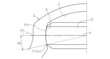
(1)ローラ11の外周面11aは、脚軸7の軸線7x上に曲率中心をおく部分球面で形成されていること。
(2)ローラ案内面6は、トラック溝5のピッチ円PCとトラック溝5の中心線との交点を通る水平線上に曲率中心をおく部分円筒面で形成されていること。
(3)継手にトルクが負荷されてない状態で、ローラ11の外周面11aの端部がローラ案内面6と当接すること。

(1)ローラユニットのインナリングが脚軸に外嵌され、ローラユニットが脚軸に対して傾斜可能であると共に、ローラがトラック溝のローラ案内面に沿って移動可能で、かつ、ローラがトラック溝内で傾斜可能なトリポード型等速自在継手において、
(2)ローラの外周面は、脚軸の軸線上に曲率中心がある部分球面で形成されていること。
(3)ローラ案内面は、前記トラック溝のピッチ円とトラック溝の中心線との交点を通る水平線上に曲率中心がある部分円筒面で形成されていること。
(4)ローラ案内面の部分円筒面の曲率半径Rと、ローラの外周面の部分球面の曲率半径rとの接触率R/rを0.95≦R/r≦1.08の範囲としたことにより、継手の誘起スラストを低減させたこと。
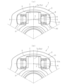
2 外側継手部材
3 トリポード部材
4 ローラユニット
5 トラック溝
5x トラック溝の中心線
6 ローラ案内面
7 脚軸
7x 脚軸の軸線
9 シャフト
11 ローラ
11a 外周面
11e 端部
12 インナリング
12a 内周面
13 針状ころ
C 接触点
K 退避部
Lc 幅方向中央領域
PC トラック溝のピッチ円
Q 丸み部
R、R’ ローラ案内面の部分円筒面の曲率半径
T 交点
X-X 水平線
a 長軸
b 短軸
m 隙間
r、r’ ローラの外周面の部分球面の曲率半径
θ 接触角
δ トラック隙間
Claims (5)
- 円周方向に対向して配置されたローラ案内面を有する3つのトラック溝が形成された外側継手部材と、半径方向に突出した3つの脚軸を備えたトリポード部材と、ローラと該ローラを回転自在に支持するインナリングとを備えたローラユニットとからなり、前記インナリングが前記脚軸に外嵌されると共に前記ローラが前記トラック溝のローラ案内面に沿って移動可能であって、前記インナリングの内周面がインナリングの縦断面において円弧状凸面に形成され、前記脚軸の外周面が、脚軸の軸線を含んだ縦断面においてはストレート形状で、かつ、前記脚軸の軸線と直交する横断面においては略楕円形状であり、前記脚軸の外周面が、継手の軸線と直交する方向で前記インナリングの内周面と当接すると共に、継手の軸線方向で前記インナリングの内周面との間にすきまが形成されており、前記ローラが前記トラック溝内で傾斜可能なトリポード型等速自在継手において、
前記ローラの外周面は、前記脚軸の軸線上に曲率中心がある部分球面で形成され、
前記ローラ案内面は、前記トラック溝のピッチ円とトラック溝の中心線との交点を通る水平線上に曲率中心がある部分円筒面で形成され、
前記ローラ案内面の部分円筒面の曲率中心は、前記トラック溝の中心線からずれた位置にあり、
前記ローラ案内面と前記ローラの外周面との間にトラック隙間が設けられ、
前記ローラ案内面の部分円筒面の曲率半径Rと、ローラの外周面の部分球面の曲率半径rとの接触率R/rを0.95≦R/r≦1.08の範囲としたことにより、
継手にトルクが負荷されてない状態で、前記ローラの外周面の端部が、ローラ直径方向の両側で前記ローラ案内面と当接することを特徴とするトリポード型等速自在継手。 - 前記インナリングと前記ローラとの間に複数の転動体を配置したことを特徴とする請求項1に記載のトリポード型等速自在継手。
- 前記転動体が針状ころであることを特徴とする請求項2にトリポード型等速自在継手。
- 前記ローラの外周面の両端部に前記ローラの外周面の部分球面の曲率半径rより小さな曲率半径をもつ丸み部が形成されていることを特徴とする請求項1に記載のトリポード型等速自在継手。
- 前記ローラの外周面は、その幅方向中央領域を部分球面とし、前記幅方向中央領域から端部までの領域に退避部を形成し中高形状にしたことを特徴とする請求項1に記載のトリポード型等速自在継手。
Priority Applications (4)
| Application Number | Priority Date | Filing Date | Title |
|---|---|---|---|
| CN202180037247.9A CN115698531A (zh) | 2020-06-01 | 2021-05-13 | 三球销型等速万向联轴器 |
| US17/927,119 US12460680B2 (en) | 2020-06-01 | 2021-05-13 | Tripod type constant velocity universal joint |
| EP21818297.0A EP4160031B1 (en) | 2020-06-01 | 2021-05-13 | Tripod-type constant-velocity universal joint |
| PCT/JP2021/018270 WO2021246129A1 (ja) | 2020-06-01 | 2021-05-13 | トリポード型等速自在継手 |
Applications Claiming Priority (2)
| Application Number | Priority Date | Filing Date | Title |
|---|---|---|---|
| JP2020095337 | 2020-06-01 | ||
| JP2020095337 | 2020-06-01 |
Publications (2)
| Publication Number | Publication Date |
|---|---|
| JP2021188742A JP2021188742A (ja) | 2021-12-13 |
| JP7664728B2 true JP7664728B2 (ja) | 2025-04-18 |
Family
ID=78848300
Family Applications (1)
| Application Number | Title | Priority Date | Filing Date |
|---|---|---|---|
| JP2021052157A Active JP7664728B2 (ja) | 2020-06-01 | 2021-03-25 | トリポード型等速自在継手 |
Country Status (1)
| Country | Link |
|---|---|
| JP (1) | JP7664728B2 (ja) |
Families Citing this family (2)
| Publication number | Priority date | Publication date | Assignee | Title |
|---|---|---|---|---|
| JP7840177B2 (ja) * | 2022-03-04 | 2026-04-03 | Ntn株式会社 | トリポード型等速自在継手 |
| JPWO2023170967A1 (ja) * | 2022-03-11 | 2023-09-14 |
Citations (5)
| Publication number | Priority date | Publication date | Assignee | Title |
|---|---|---|---|---|
| US20030232655A1 (en) | 2002-06-14 | 2003-12-18 | Delphi Technologies Inc. | Tripot universal joint |
| JP2005054834A (ja) | 2003-07-31 | 2005-03-03 | Ntn Corp | トリポード型等速自在継手 |
| JP2005098402A (ja) | 2003-09-25 | 2005-04-14 | Ntn Corp | トリポード型等速自在継手 |
| US20090312108A1 (en) | 2008-06-13 | 2009-12-17 | Wia Corporation | Constant velocity joint of tripod type |
| JP2020046063A (ja) | 2018-09-21 | 2020-03-26 | Ntn株式会社 | トリポード型等速自在継手 |
Family Cites Families (1)
| Publication number | Priority date | Publication date | Assignee | Title |
|---|---|---|---|---|
| KR100664886B1 (ko) * | 2005-06-23 | 2007-01-04 | 오승탁 | 마찰저감형 트라이포드 등속조인트 |
-
2021
- 2021-03-25 JP JP2021052157A patent/JP7664728B2/ja active Active
Patent Citations (5)
| Publication number | Priority date | Publication date | Assignee | Title |
|---|---|---|---|---|
| US20030232655A1 (en) | 2002-06-14 | 2003-12-18 | Delphi Technologies Inc. | Tripot universal joint |
| JP2005054834A (ja) | 2003-07-31 | 2005-03-03 | Ntn Corp | トリポード型等速自在継手 |
| JP2005098402A (ja) | 2003-09-25 | 2005-04-14 | Ntn Corp | トリポード型等速自在継手 |
| US20090312108A1 (en) | 2008-06-13 | 2009-12-17 | Wia Corporation | Constant velocity joint of tripod type |
| JP2020046063A (ja) | 2018-09-21 | 2020-03-26 | Ntn株式会社 | トリポード型等速自在継手 |
Also Published As
| Publication number | Publication date |
|---|---|
| JP2021188742A (ja) | 2021-12-13 |
Similar Documents
| Publication | Publication Date | Title |
|---|---|---|
| US7682253B2 (en) | Tripod type constant velocity joint | |
| AU742472B2 (en) | Constant velocity universal joint | |
| JP7664728B2 (ja) | トリポード型等速自在継手 | |
| JPH04307116A (ja) | 同期回り継手 | |
| US8608578B2 (en) | Constant velocity joint of tripod type | |
| US7217194B2 (en) | Constant velocity universal joint | |
| EP1253337B1 (en) | Constant velocity joint | |
| JP7166859B2 (ja) | トリポード型等速自在継手 | |
| EP1489323B1 (en) | Constant velocity universal joint | |
| CN219809306U (zh) | 三球销型等速万向联轴器 | |
| WO2015071877A1 (en) | Improved torque-transmitting joint and joint components, methods of manufacturing, and methods of inspection | |
| WO2024127952A1 (ja) | トリポード型等速自在継手 | |
| JP2008509345A (ja) | 回転ホモキネティックジョイント | |
| WO2021246129A1 (ja) | トリポード型等速自在継手 | |
| JP3949865B2 (ja) | 等速自在継手 | |
| JP7796787B2 (ja) | トリポード型等速自在継手 | |
| US20070049380A1 (en) | Tripod type constant velocity universal joint | |
| JP4574242B2 (ja) | トリポード型等速自在継手 | |
| JPH08312660A (ja) | すべり自在継手 | |
| KR20250005476A (ko) | 트라이포드 조인트 | |
| WO2025258342A1 (ja) | トリポード型等速自在継手 | |
| JP2025139917A (ja) | トリポード型等速自在継手 | |
| WO2025187206A1 (ja) | トリポード型等速自在継手 | |
| JP2025139922A (ja) | トリポード型等速自在継手 |
Legal Events
| Date | Code | Title | Description |
|---|---|---|---|
| A621 | Written request for application examination |
Free format text: JAPANESE INTERMEDIATE CODE: A621 Effective date: 20240226 |
|
| A131 | Notification of reasons for refusal |
Free format text: JAPANESE INTERMEDIATE CODE: A131 Effective date: 20240531 |
|
| A521 | Request for written amendment filed |
Free format text: JAPANESE INTERMEDIATE CODE: A523 Effective date: 20240725 |
|
| A02 | Decision of refusal |
Free format text: JAPANESE INTERMEDIATE CODE: A02 Effective date: 20240930 |
|
| A521 | Request for written amendment filed |
Free format text: JAPANESE INTERMEDIATE CODE: A523 Effective date: 20241217 |
|
| A911 | Transfer to examiner for re-examination before appeal (zenchi) |
Free format text: JAPANESE INTERMEDIATE CODE: A911 Effective date: 20241224 |
|
| TRDD | Decision of grant or rejection written | ||
| A01 | Written decision to grant a patent or to grant a registration (utility model) |
Free format text: JAPANESE INTERMEDIATE CODE: A01 Effective date: 20250324 |
|
| A61 | First payment of annual fees (during grant procedure) |
Free format text: JAPANESE INTERMEDIATE CODE: A61 Effective date: 20250408 |
|
| R150 | Certificate of patent or registration of utility model |
Ref document number: 7664728 Country of ref document: JP Free format text: JAPANESE INTERMEDIATE CODE: R150 |