JP7675676B2 - 通信装置、及び半導体装置 - Google Patents
通信装置、及び半導体装置 Download PDFInfo
- Publication number
- JP7675676B2 JP7675676B2 JP2022034687A JP2022034687A JP7675676B2 JP 7675676 B2 JP7675676 B2 JP 7675676B2 JP 2022034687 A JP2022034687 A JP 2022034687A JP 2022034687 A JP2022034687 A JP 2022034687A JP 7675676 B2 JP7675676 B2 JP 7675676B2
- Authority
- JP
- Japan
- Prior art keywords
- signal
- pulse signal
- sub
- circuit
- pulse
- Prior art date
- Legal status (The legal status is an assumption and is not a legal conclusion. Google has not performed a legal analysis and makes no representation as to the accuracy of the status listed.)
- Active
Links
Images




Classifications
-
- H—ELECTRICITY
- H04—ELECTRIC COMMUNICATION TECHNIQUE
- H04L—TRANSMISSION OF DIGITAL INFORMATION, e.g. TELEGRAPHIC COMMUNICATION
- H04L25/00—Baseband systems
- H04L25/02—Details ; arrangements for supplying electrical power along data transmission lines
- H04L25/026—Arrangements for coupling transmitters, receivers or transceivers to transmission lines; Line drivers
-
- H—ELECTRICITY
- H02—GENERATION; CONVERSION OR DISTRIBUTION OF ELECTRIC POWER
- H02M—APPARATUS FOR CONVERSION BETWEEN AC AND AC, BETWEEN AC AND DC, OR BETWEEN DC AND DC, AND FOR USE WITH MAINS OR SIMILAR POWER SUPPLY SYSTEMS; CONVERSION OF DC OR AC INPUT POWER INTO SURGE OUTPUT POWER; CONTROL OR REGULATION THEREOF
- H02M3/00—Conversion of DC power input into DC power output
- H02M3/22—Conversion of DC power input into DC power output with intermediate conversion into AC
- H02M3/24—Conversion of DC power input into DC power output with intermediate conversion into AC by static converters
- H02M3/28—Conversion of DC power input into DC power output with intermediate conversion into AC by static converters using discharge tubes with control electrode or semiconductor devices with control electrode to produce the intermediate AC
- H02M3/325—Conversion of DC power input into DC power output with intermediate conversion into AC by static converters using discharge tubes with control electrode or semiconductor devices with control electrode to produce the intermediate AC using devices of a triode or a transistor type requiring continuous application of a control signal
- H02M3/335—Conversion of DC power input into DC power output with intermediate conversion into AC by static converters using discharge tubes with control electrode or semiconductor devices with control electrode to produce the intermediate AC using devices of a triode or a transistor type requiring continuous application of a control signal using semiconductor devices only
- H02M3/33507—Conversion of DC power input into DC power output with intermediate conversion into AC by static converters using discharge tubes with control electrode or semiconductor devices with control electrode to produce the intermediate AC using devices of a triode or a transistor type requiring continuous application of a control signal using semiconductor devices only with automatic control of the output voltage or current, e.g. flyback converters
- H02M3/33523—Conversion of DC power input into DC power output with intermediate conversion into AC by static converters using discharge tubes with control electrode or semiconductor devices with control electrode to produce the intermediate AC using devices of a triode or a transistor type requiring continuous application of a control signal using semiconductor devices only with automatic control of the output voltage or current, e.g. flyback converters with galvanic isolation between input and output of both the power stage and the feedback loop
-
- H—ELECTRICITY
- H02—GENERATION; CONVERSION OR DISTRIBUTION OF ELECTRIC POWER
- H02M—APPARATUS FOR CONVERSION BETWEEN AC AND AC, BETWEEN AC AND DC, OR BETWEEN DC AND DC, AND FOR USE WITH MAINS OR SIMILAR POWER SUPPLY SYSTEMS; CONVERSION OF DC OR AC INPUT POWER INTO SURGE OUTPUT POWER; CONTROL OR REGULATION THEREOF
- H02M1/00—Details of apparatus for conversion
- H02M1/08—Circuits specially adapted for the generation of control voltages for semiconductor devices incorporated in static converters
-
- H—ELECTRICITY
- H04—ELECTRIC COMMUNICATION TECHNIQUE
- H04B—TRANSMISSION
- H04B1/00—Details of transmission systems, not covered by a single one of groups H04B3/00 - H04B13/00; Details of transmission systems not characterised by the medium used for transmission
- H04B1/02—Transmitters
- H04B1/04—Circuits
-
- H—ELECTRICITY
- H04—ELECTRIC COMMUNICATION TECHNIQUE
- H04B—TRANSMISSION
- H04B5/00—Near-field transmission systems, e.g. inductive or capacitive transmission systems
- H04B5/20—Near-field transmission systems, e.g. inductive or capacitive transmission systems characterised by the transmission technique; characterised by the transmission medium
- H04B5/22—Capacitive coupling
-
- H—ELECTRICITY
- H04—ELECTRIC COMMUNICATION TECHNIQUE
- H04L—TRANSMISSION OF DIGITAL INFORMATION, e.g. TELEGRAPHIC COMMUNICATION
- H04L25/00—Baseband systems
- H04L25/02—Details ; arrangements for supplying electrical power along data transmission lines
- H04L25/08—Modifications for reducing interference; Modifications for reducing effects due to line faults ; Receiver end arrangements for detecting or overcoming line faults
Landscapes
- Engineering & Computer Science (AREA)
- Computer Networks & Wireless Communication (AREA)
- Signal Processing (AREA)
- Power Engineering (AREA)
- Electronic Switches (AREA)
- Detection And Prevention Of Errors In Transmission (AREA)
- Dc Digital Transmission (AREA)
Description
図1及び図2を用いて通信装置1の構成例を説明する。図1は、通信装置1の構成例を示すブロック図である。図1に示すように、通信装置1は、例えばデジタルアイソレーであり、送信側と受信側とが電気的に絶縁された状態で、デジタルの論理信号を伝送するための装置である。このデジタルアイソレータは、CMOSプロセスなどの汎用性の高い半導体プロセスを適用して形成することが可能な半導体装置である。
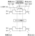
例えばガルバニック絶縁を確保しながら、パルス信号Spi1、Sni1に応じた微分波Dpi02、Dni02を2次側の受信回路20に伝送する。交流結合素子108は、微分波Dpi02、Dni02を増幅器110に出力する。なお、本実施形態に係る交流結合素子108は、絶縁マイクロトランスであるがこれに限定されない。例えば、交流結合素子108は、ガルバニック絶縁された絶縁マイクロキャパシタでもよい。


Claims (10)
- 送信回路を備える通信装置であって、
前記送信回路は、符号化器を有し、
前記符号化器は、
論理信号の立ち上がりに応じた第1主パルス信号と、立ち下がりに応じた第2主パルス信号と、を生成する主パルス信号生成回路と、
前記第1主パルス信号を生成した所定時間後に前記第1主パルス信号に対応する第1副パルス信号を所定の間隔で生成する第1生成処理、及び、前記第2主パルス信号を生成した所定時間後に前記第2主パルス信号に対応する第2副パルス信号を所定の間隔で生成する第2生成処理の少なくとも一方を行う副パルス信号生成回路と、
前記第1主パルス信号、前記第2主パルス信号、前記第1副パルス信号、及び前記第2副パルス信号の少なくともいずれかを出力する出力回路と、有し、
前記出力回路は、前記第1副パルス信号、及び前記第2副パルス信号の少なくとも一方の出力を停止する、通信装置。 - 前記出力回路は、前記立ち上がり、及び前記立ち下がりの少なくとも一方に応じて、前記第1副パルス信号、及び前記第2副パルス信号の少なくとも一方の出力を停止する、請求項1に記載の通信装置。
- 前記第1主パルス信号は、複数のパルス信号の第1組合せであり、前記第2主パルス信号は、前記第1組合せと異なる複数のパルス信号の第2組合せである、請求項1に記載の通信装置。
- 受信回路を更に備え、
前記受信回路は、復号器を有し、
前記復号器は、
前記第1主パルス信号、及び前記第1副パルス信号それぞれに対応する第3主パルス信号、及び第3副パルス信号それぞれに応じてハイレベル信号を生成し、
前記第2主パルス信号、及び前記第2副パルス信号それぞれに対応する第4主パルス信号、及び第4副パルス信号のいずれかが入力されるまでハイレベル信号を出力する信号保持回路を有する、請求項1に記載の通信装置。 - 前記復号器は、
前記第4主パルス信号及び前記第4副パルス信号それぞれに応じてロウレベル信号を生成し、
前記信号保持回路は、第3主パルス信号、及び第3副パルス信号のいずれかが入力されるまでロウレベル信号を出力する、請求項4に記載の通信装置。 - 前記第1副パルス信号は、複数のパルス信号の第1組合せであり、前記第2副パルス信号は、前記第1組合せと異なる複数のパルス信号の第2組合せであり、
前記復号器は、前記第1副パルス信号、及び前記第2副パルス信号に応じてリフレッシュ動作を行う、請求項5に記載の通信装置。 - 前記復号器は、
前記第3主パルス信号、前記第3副パルス信号、前記第4主パルス信号及び前記第4副パルス信号が有する複数パルス信号の中の一番目のパルス信号に応じて所定信号を出力する第1パルス検出回路と、
前記第1パルス検出回路の出力信号に少なくとも基づき、前記第3主パルス信号、前記第3副パルス信号、前記第4主パルス信号及び前記第4副パルス信号が有する複数パルス信号のなかの2番目のパルス信号に応じて所定信号を出力する第2パルス検出回路と、
前記第2パルス検出回路の出力信号に少なくとも基づき、前記立ち上がりに応じた第1信号、前記立ち下がりに応じた第2信号を出力する検出回路と、
前記第3主パルス信号、前記第3副パルス信号、前記第4主パルス信号及び前記第4副パルス信号のそれぞれが有する複数パルス信号の中の最後のパルス信号に応じて、前記第1パルス検出回路、及び前記第2パルス検出回路を初期値にするリセット信号を生成するリセット回路と、を有し、
前記信号保持回路は、前記第1信号及び第2信号に応じて、前記ハイレベル信号又は前記ロウレベル信号を出力する、請求項6に記載の通信装置。 - 前記出力回路が出力する前記第1主パルス信号、前記第2主パルス信号、前記第1副パルス信号、及び前記第2副パルス信号の少なくともいずれかを前記受信回路に伝送する交流結合素子を更に備える、請求項4に記載された通信装置。
- 前記交流結合素子は、絶縁マイクロトランス、及びマイクロキャパシタのいずれかでありであり、
前記送信回路と前記受信回路とは、前記絶縁マイクロトランス、及び前記マイクロキャパシタのいずれかによってガルバニック絶縁される、請求項8に記載の通信装置。 - 符号化器を備える半導体装置であって、
前記符号化器は、
論理信号の立ち上がりに応じた第1主パルス信号と、立ち下がりに応じた第2主パルス信号と、を生成する主パルス信号生成回路と、
前記第1主パルス信号を生成した所定時間後に前記第1主パルス信号に対応する第1副パルス信号を所定の間隔で生成する第1生成処理、及び、前記第2主パルス信号を生成した所定時間後に前記第2主パルス信号に対応する第2副パルス信号を所定の間隔で生成する第2生成処理の少なくとも一方を行う副パルス信号生成回路と、
前記第1主パルス信号、前記第2主パルス信号、前記第1副パルス信号、及び前記第2副パルス信号の少なくともいずれかを出力する出力回路と、有し、
前記出力回路は、前記第1副パルス信号、及び前記第2副パルス信号の少なくとも一方の出力を停止する、半導体装置。
Priority Applications (3)
| Application Number | Priority Date | Filing Date | Title |
|---|---|---|---|
| JP2022034687A JP7675676B2 (ja) | 2022-03-07 | 2022-03-07 | 通信装置、及び半導体装置 |
| CN202210938147.XA CN116781458A (zh) | 2022-03-07 | 2022-08-05 | 通信装置以及半导体装置 |
| US17/941,681 US12278567B2 (en) | 2022-03-07 | 2022-09-09 | Communication apparatus and semiconductor device |
Applications Claiming Priority (1)
| Application Number | Priority Date | Filing Date | Title |
|---|---|---|---|
| JP2022034687A JP7675676B2 (ja) | 2022-03-07 | 2022-03-07 | 通信装置、及び半導体装置 |
Publications (2)
| Publication Number | Publication Date |
|---|---|
| JP2023130171A JP2023130171A (ja) | 2023-09-20 |
| JP7675676B2 true JP7675676B2 (ja) | 2025-05-13 |
Family
ID=87850003
Family Applications (1)
| Application Number | Title | Priority Date | Filing Date |
|---|---|---|---|
| JP2022034687A Active JP7675676B2 (ja) | 2022-03-07 | 2022-03-07 | 通信装置、及び半導体装置 |
Country Status (3)
| Country | Link |
|---|---|
| US (1) | US12278567B2 (ja) |
| JP (1) | JP7675676B2 (ja) |
| CN (1) | CN116781458A (ja) |
Citations (6)
| Publication number | Priority date | Publication date | Assignee | Title |
|---|---|---|---|---|
| JP2009060272A (ja) | 2007-08-30 | 2009-03-19 | Toyota Industries Corp | 信号伝達回路 |
| WO2009128486A1 (ja) | 2008-04-18 | 2009-10-22 | ソニー株式会社 | 磁気メモリ素子の記録方法 |
| JP2014207668A (ja) | 2013-04-08 | 2014-10-30 | アバゴ・テクノロジーズ・ジェネラル・アイピー(シンガポール)プライベート・リミテッド | アイソレーターを介するデジタル信号及びアナログ信号の送受信 |
| JP2016046723A (ja) | 2014-08-25 | 2016-04-04 | ルネサスエレクトロニクス株式会社 | 受信装置、通信装置、及び通信方法 |
| JP2016174346A (ja) | 2015-03-17 | 2016-09-29 | ルネサスエレクトロニクス株式会社 | 送信回路、半導体装置及びデータ送信方法 |
| JP2019102822A (ja) | 2017-11-28 | 2019-06-24 | 三菱電機株式会社 | デジタルアイソレータおよび駆動装置 |
Family Cites Families (11)
| Publication number | Priority date | Publication date | Assignee | Title |
|---|---|---|---|---|
| EP1940025A1 (fr) * | 2006-12-28 | 2008-07-02 | St Microelectronics S.A. | Transfert de données numériques à travers un isolement |
| JP5566153B2 (ja) * | 2010-03-29 | 2014-08-06 | パナソニック株式会社 | 絶縁通信システム |
| US8847503B2 (en) | 2010-09-21 | 2014-09-30 | Avago Technologies General Ip (Singapore) Pte. Ltd. | Transmitting and receiving digital and analog signals across an isolator |
| JP5880225B2 (ja) * | 2012-04-02 | 2016-03-08 | 富士電機株式会社 | 半導体装置 |
| US9143373B2 (en) * | 2013-08-30 | 2015-09-22 | Silicon Laboratories Inc. | Transport of an analog signal across an isolation barrier |
| EP3070896A1 (en) | 2015-03-17 | 2016-09-21 | Renesas Electronics Corporation | Transmitter circuit, semiconductor apparatus and data transmission method |
| JP2017147538A (ja) | 2016-02-16 | 2017-08-24 | 三菱電機株式会社 | アイソレータ及びアイソレーション方法 |
| US9941999B1 (en) * | 2017-03-08 | 2018-04-10 | Allegro Microsystems, Llc | Methods and apparatus for communication over an isolation barrier with monitoring |
| JP7119757B2 (ja) | 2018-08-21 | 2022-08-17 | 富士通株式会社 | パルス位置変調回路及び送信回路 |
| US11637724B2 (en) * | 2021-03-12 | 2023-04-25 | Analog Devices, Inc. | Coding schemes for communicating multiple logic states through a digital isolator |
| US11515900B1 (en) * | 2021-07-30 | 2022-11-29 | Amazing Microelectronics Corp. | Transmitter circuit |
-
2022
- 2022-03-07 JP JP2022034687A patent/JP7675676B2/ja active Active
- 2022-08-05 CN CN202210938147.XA patent/CN116781458A/zh active Pending
- 2022-09-09 US US17/941,681 patent/US12278567B2/en active Active
Patent Citations (7)
| Publication number | Priority date | Publication date | Assignee | Title |
|---|---|---|---|---|
| JP2009060272A (ja) | 2007-08-30 | 2009-03-19 | Toyota Industries Corp | 信号伝達回路 |
| WO2009128486A1 (ja) | 2008-04-18 | 2009-10-22 | ソニー株式会社 | 磁気メモリ素子の記録方法 |
| US20110032744A1 (en) | 2008-04-18 | 2011-02-10 | Sony Corporation | Recording method for magnetic memory device |
| JP2014207668A (ja) | 2013-04-08 | 2014-10-30 | アバゴ・テクノロジーズ・ジェネラル・アイピー(シンガポール)プライベート・リミテッド | アイソレーターを介するデジタル信号及びアナログ信号の送受信 |
| JP2016046723A (ja) | 2014-08-25 | 2016-04-04 | ルネサスエレクトロニクス株式会社 | 受信装置、通信装置、及び通信方法 |
| JP2016174346A (ja) | 2015-03-17 | 2016-09-29 | ルネサスエレクトロニクス株式会社 | 送信回路、半導体装置及びデータ送信方法 |
| JP2019102822A (ja) | 2017-11-28 | 2019-06-24 | 三菱電機株式会社 | デジタルアイソレータおよび駆動装置 |
Also Published As
| Publication number | Publication date |
|---|---|
| JP2023130171A (ja) | 2023-09-20 |
| US20230283187A1 (en) | 2023-09-07 |
| US12278567B2 (en) | 2025-04-15 |
| CN116781458A (zh) | 2023-09-19 |
Similar Documents
| Publication | Publication Date | Title |
|---|---|---|
| US7701257B2 (en) | Data receiver and semiconductor device including the data receiver | |
| US10038346B2 (en) | Transmission unit, reception unit, and communication system | |
| US9479363B2 (en) | Partial response receiver and related method | |
| US6583647B2 (en) | Signal converting system having level converter for use in high speed semiconductor device and method therefor | |
| US11626869B2 (en) | Comparator and decision feedback equalization circuit | |
| JP7675676B2 (ja) | 通信装置、及び半導体装置 | |
| US11073862B2 (en) | Synchronization circuit and cascaded synchronization circuit for converting asynchronous signal into synchronous signal | |
| CN107809285B (zh) | 一种用于突发模式接收机的限幅放大器 | |
| KR102478263B1 (ko) | 하이브리드 송신기, 이의 동작 방법 및 이를 포함하는 송수신 시스템 | |
| US11481217B2 (en) | Data transmitting and receiving system including clock and data recovery device and operating method of the data transmitting and receiving system | |
| KR102657607B1 (ko) | 듀오바이너리 신호를 송수신하는 트랜시버 및 그 동작 방법 | |
| JP3562964B2 (ja) | スキュー抑制のための調整機能を備えた信号伝送システムおよび方法 | |
| KR102410192B1 (ko) | 표본 및 보존 회로를 이용하는 싱글 엔디드 수신기 및 그 동작 방법 | |
| US6441644B1 (en) | Logic device for outputting a signal within a through rate range | |
| JP4460182B2 (ja) | 信号補償回路及び復調回路 | |
| CN110247734B (zh) | 一种数据传输方法、装置及电子设备 | |
| US12155508B2 (en) | Digital isolator | |
| US3978283A (en) | Switching arrangement for receiving dc signals | |
| US20140103972A1 (en) | Duty cycle protection circuit | |
| US11249510B2 (en) | Semiconductor apparatus with domain crossing function | |
| US20240322836A1 (en) | Receiver device, communication system, and reception method | |
| JP2026055545A (ja) | 通信システム | |
| US20260065970A1 (en) | Signal processing circuit and memory | |
| JP2017220820A (ja) | 受信装置 | |
| KR20240174378A (ko) | Vtc 및 이의 동작 방법 |
Legal Events
| Date | Code | Title | Description |
|---|---|---|---|
| A621 | Written request for application examination |
Free format text: JAPANESE INTERMEDIATE CODE: A621 Effective date: 20240611 |
|
| A977 | Report on retrieval |
Free format text: JAPANESE INTERMEDIATE CODE: A971007 Effective date: 20250117 |
|
| A131 | Notification of reasons for refusal |
Free format text: JAPANESE INTERMEDIATE CODE: A131 Effective date: 20250128 |
|
| A521 | Request for written amendment filed |
Free format text: JAPANESE INTERMEDIATE CODE: A523 Effective date: 20250326 |
|
| TRDD | Decision of grant or rejection written | ||
| A01 | Written decision to grant a patent or to grant a registration (utility model) |
Free format text: JAPANESE INTERMEDIATE CODE: A01 Effective date: 20250404 |
|
| A61 | First payment of annual fees (during grant procedure) |
Free format text: JAPANESE INTERMEDIATE CODE: A61 Effective date: 20250428 |
|
| R150 | Certificate of patent or registration of utility model |
Ref document number: 7675676 Country of ref document: JP Free format text: JAPANESE INTERMEDIATE CODE: R150 |