JP7692000B2 - System and method for identifying human visual axis - Google Patents
System and method for identifying human visual axis Download PDFInfo
- Publication number
- JP7692000B2 JP7692000B2 JP2022562383A JP2022562383A JP7692000B2 JP 7692000 B2 JP7692000 B2 JP 7692000B2 JP 2022562383 A JP2022562383 A JP 2022562383A JP 2022562383 A JP2022562383 A JP 2022562383A JP 7692000 B2 JP7692000 B2 JP 7692000B2
- Authority
- JP
- Japan
- Prior art keywords
- eye
- patient
- multifocal
- visual axis
- location
- Prior art date
- Legal status (The legal status is an assumption and is not a legal conclusion. Google has not performed a legal analysis and makes no representation as to the accuracy of the status listed.)
- Active
Links
Images








Classifications
-
- A—HUMAN NECESSITIES
- A61—MEDICAL OR VETERINARY SCIENCE; HYGIENE
- A61B—DIAGNOSIS; SURGERY; IDENTIFICATION
- A61B3/00—Apparatus for testing the eyes; Instruments for examining the eyes
- A61B3/10—Objective types, i.e. instruments for examining the eyes independent of the patients' perceptions or reactions
- A61B3/113—Objective types, i.e. instruments for examining the eyes independent of the patients' perceptions or reactions for determining or recording eye movement
-
- A—HUMAN NECESSITIES
- A61—MEDICAL OR VETERINARY SCIENCE; HYGIENE
- A61B—DIAGNOSIS; SURGERY; IDENTIFICATION
- A61B3/00—Apparatus for testing the eyes; Instruments for examining the eyes
- A61B3/10—Objective types, i.e. instruments for examining the eyes independent of the patients' perceptions or reactions
- A61B3/103—Objective types, i.e. instruments for examining the eyes independent of the patients' perceptions or reactions for determining refraction, e.g. refractometers, skiascopes
-
- A—HUMAN NECESSITIES
- A61—MEDICAL OR VETERINARY SCIENCE; HYGIENE
- A61B—DIAGNOSIS; SURGERY; IDENTIFICATION
- A61B3/00—Apparatus for testing the eyes; Instruments for examining the eyes
- A61B3/0016—Operational features thereof
- A61B3/0025—Operational features thereof characterised by electronic signal processing, e.g. eye models
-
- A—HUMAN NECESSITIES
- A61—MEDICAL OR VETERINARY SCIENCE; HYGIENE
- A61B—DIAGNOSIS; SURGERY; IDENTIFICATION
- A61B3/00—Apparatus for testing the eyes; Instruments for examining the eyes
- A61B3/0091—Fixation targets for viewing direction
-
- A—HUMAN NECESSITIES
- A61—MEDICAL OR VETERINARY SCIENCE; HYGIENE
- A61B—DIAGNOSIS; SURGERY; IDENTIFICATION
- A61B3/00—Apparatus for testing the eyes; Instruments for examining the eyes
- A61B3/10—Objective types, i.e. instruments for examining the eyes independent of the patients' perceptions or reactions
- A61B3/14—Arrangements specially adapted for eye photography
Landscapes
- Health & Medical Sciences (AREA)
- Life Sciences & Earth Sciences (AREA)
- Engineering & Computer Science (AREA)
- Surgery (AREA)
- General Health & Medical Sciences (AREA)
- Biophysics (AREA)
- Biomedical Technology (AREA)
- Heart & Thoracic Surgery (AREA)
- Medical Informatics (AREA)
- Molecular Biology (AREA)
- Physics & Mathematics (AREA)
- Animal Behavior & Ethology (AREA)
- Ophthalmology & Optometry (AREA)
- Public Health (AREA)
- Veterinary Medicine (AREA)
- Signal Processing (AREA)
- Human Computer Interaction (AREA)
- Prostheses (AREA)
- Eye Examination Apparatus (AREA)
- Eyeglasses (AREA)
- Magnetic Resonance Imaging Apparatus (AREA)
Description
本開示の実施形態は、一般的には視覚を特徴付ける方法及び装置に関し、より詳細には眼の視軸を正確に識別する方法及び装置に関する。 Embodiments of the present disclosure relate generally to methods and apparatus for characterizing vision, and more particularly to methods and apparatus for accurately identifying the visual axis of the eye.
老眼治療の従来の技法は典型的には、患者の各眼の視軸の相対場所を特定することを含む。これらの軸の正確な特定は、小面積の二焦点、多焦点、及び拡張焦点深度(EDOF)眼内レンズ(IOL)を有効に配置するのに極めて重要である。これらの軸のわずかな位置合わせずれであっても、その外科的移植によって意図されるあらゆる恩恵を大きく損なう恐れがある。また、視軸の特定から恩恵を受け得る老眼治療の他の例として少数を挙げれば、LASIK、プレスビーLASIK、又は多焦点LASIK、及びレーザー屈折矯正角膜切除(PRK)術がある。 Conventional techniques for treating presbyopia typically involve identifying the relative location of the visual axis of each eye of a patient. Accurate identification of these axes is crucial for effective placement of small area bifocal, multifocal, and extended depth of focus (EDOF) intraocular lenses (IOLs). Even slight misalignment of these axes can seriously compromise any intended benefit of their surgical implantation. Other examples of presbyopia treatments that may also benefit from identification of the visual axis include LASIK, Presby LASIK, or multifocal LASIK, and laser photorefractive keratectomy (PRK), to name a few.
視軸とは、網膜における小さな窪みであり、固視点が患者の視野にある状態で最もクリアな視点である眼の中心窩に合流する直線である実際の視線である。したがって、視軸の測定は二焦点及び多層点レンズの配置を決めるのに極めて重要であり、何故ならば、そのようなレンズの視域は狭く、わずかな位置合わせずれであってもそれらの機能を大きく損なう恐れがあるためである。現在、視軸の場所を正確且つ精密に特定する診断デバイスはない。代わりに、視軸の場所は一般に、光軸と角膜頂又は角膜外面での固視光の反射である第1プルキンエ像との間の中間として近似される。この方法は、視軸は上記中間点から遠く離れて位置することがある(例えば特に損傷のある眼又は通常の形状ではない眼で)ため、往々にして不正確である。 The visual axis is the actual line of sight, which is a small depression in the retina and a straight line that meets the fovea of the eye, which is the clearest line of sight when the fixation point is in the patient's field of vision. Therefore, measuring the visual axis is crucial for positioning bifocal and multi-point lenses, because such lenses have a small viewing zone and even slight misalignment can seriously impair their function. Currently, there are no diagnostic devices that pinpoint the location of the visual axis accurately and precisely. Instead, the location of the visual axis is generally approximated as the midpoint between the optical axis and the first Purkinje image, which is the reflection of the fixation light at the corneal apex or outer surface of the cornea. This method is often inaccurate, because the visual axis can be located far away from the midpoint (e.g., especially in damaged or abnormally shaped eyes).
したがって、当該分野では、眼の視軸を識別する方法及び装置の改良が必要とされている。 Therefore, there is a need in the art for improved methods and devices for identifying the visual axis of the eye.
本開示は、一般的には眼の視軸を正確に識別する方法及び装置に関する。 The present disclosure generally relates to methods and apparatus for accurately identifying the visual axis of the eye.
特定の実施形態において、患者の眼の視軸の場所を特定する方法が提供される。本方法は、患者の眼に隣接して多焦点光学レンズを配置することを含み、多焦点光学レンズは、多焦点光学レンズの光学中心に、対応する空間的に一致する光学中心を有する2つ以上の屈折力を含む。固視光ビームを生成し、患者の眼に向け、固視光ビームは、多焦点レンズの2つ以上の屈折力に対応する2つ以上の像を患者の網膜近くに形成する。本方法は、固視光ビームの方向に沿った患者の眼及び光学レンズの画像を捕捉することと、多焦点光学レンズの光学中心のX/Y場所に対する患者の眼のX/Y場所を特定することとを更に含む。多焦点光学レンズは、患者のビューにおいて2つ以上の像の中心が一致するまで、患者が注視を固視光に維持する間、X/Y方向に沿って移動する。その時点で、患者の眼の視軸の場所は、患者の眼の瞳面において検出、位置特定され、視軸の場所は、固視光ビームの方向から見た多焦点光学レンズの光学中心の場所に対応する。 In certain embodiments, a method of locating a visual axis of a patient's eye is provided. The method includes positioning a multifocal optical lens adjacent to the patient's eye, the multifocal optical lens including two or more refractive powers with corresponding spatially coincident optical centers at the optical center of the multifocal optical lens. A fixation light beam is generated and directed at the patient's eye, the fixation light beam forming two or more images near the patient's retina corresponding to the two or more refractive powers of the multifocal lens. The method further includes capturing an image of the patient's eye and the optical lens along the direction of the fixation light beam and locating an X/Y location of the patient's eye relative to the X/Y location of the optical center of the multifocal optical lens. The multifocal optical lens is moved along the X/Y direction while the patient maintains gaze on the fixation light until the centers of the two or more images coincide in the patient's view. At that point, a location of the visual axis of the patient's eye is detected and located in a pupil plane of the patient's eye, the location of the visual axis corresponding to the location of the optical center of the multifocal optical lens as viewed from the direction of the fixation light beam.
上記で列挙した本開示の特徴を詳細に理解できるように、上記で簡潔に要約した本開示のより詳細な説明が、実施形態を参照することによって得られ得、そのうちのいくつかを添付図面に示す。しかしながら、添付図面は、例示的な実施形態を示すにすぎないため、その範囲を限定するとみなされるべきではなく、他の同様に効果的な実施形態が認められ得ることに留意すべきである。 So that the above-listed features of the present disclosure can be understood in detail, a more detailed description of the present disclosure briefly summarized above can be obtained by reference to embodiments, some of which are illustrated in the accompanying drawings. It should be noted, however, that the accompanying drawings only illustrate exemplary embodiments and should not be considered as limiting the scope thereof, as other equally effective embodiments may be recognized.
理解を容易にするために、可能な場合、複数の図に共通する同一の要素を示すために、同一の参照符号が使用されている。1つの実施形態の要素及び特徴は、更に記述することなく他の実施形態に有益に組み込まれ得ることが考えられる。 For ease of understanding, wherever possible, identical reference numerals have been used to indicate identical elements that are common to multiple figures. It is contemplated that elements and features of one embodiment may be beneficially incorporated in other embodiments without further description.
本開示は、一般的には眼の視軸を正確に識別する方法及び装置に関する。特定の実施形態において、視軸識別システムは、固視光源、カメラ、処理システム、及び多焦点レンズを含む。多焦点レンズは、患者又は患者外デバイスによって装着される検眼用フレームに結合し得る。患者の視軸の場所を特定するに当たり、患者は多焦点レンズを通して、固視光源によって提供される固視光ビームを注視する。固視光ビームが多焦点レンズを通ると、患者の網膜上又はその近くに2つ以上の像が作成される。患者が固視光ビームへの注視を連続して維持している間、多焦点レンズ及び/又は患者の眼を次いで互いに対して移動させる。患者の視軸は、多焦点像の中心が網膜上で一致するとき、患者の眼に対する多焦点検眼レンズの光学中心の場所を特定することによって位置特定し得る。 The present disclosure generally relates to methods and apparatus for accurately identifying the visual axis of an eye. In certain embodiments, the visual axis identification system includes a fixation light source, a camera, a processing system, and a multifocal lens. The multifocal lens may be coupled to an ophthalmic frame worn by the patient or a patient-external device. In locating the patient's visual axis, the patient gazes through the multifocal lens at a fixation light beam provided by a fixation light source. As the fixation light beam passes through the multifocal lens, two or more images are created on or near the patient's retina. The multifocal lens and/or the patient's eye are then moved relative to each other while the patient continuously maintains gaze on the fixation light beam. The patient's visual axis may be located by locating the optical center of the multifocal ophthalmic lens relative to the patient's eye when the centers of the multifocal images coincide on the retina.
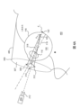
図1は、例示的な人間の眼100の簡易化された断面上面図を示す。眼100のこめかみ側及び鼻側が参照のために図1に示されている。一般に、眼100は、角膜104、中心106が示されている瞳、虹彩108、自然の水晶体110、毛様筋112、及び網膜116を含む。瞳孔軸118は虹彩108の平面に直交し、瞳孔中心106を通る。
FIG. 1 shows a simplified cross-sectional top view of an exemplary
図1は、固視点P1角膜104及び瞳孔を通り、網膜116における小さな窪みとして参照される中心窩122への視軸120を更に示す。視野の中心は中心窩122で結像し、中心窩122において、錐体が特に集中しており、したがって、視力は視軸120に沿って最も高い。したがって、視軸120の場所130の正確な特定は、二焦点又は多焦点矯正レンズの位置合わせ成功にとって極めて重要である。視軸120の場所130は、視軸120が通る虹彩108の平面又は瞳面上の点のX/Y位置又は場所を指す。しかしながら上述したように、現在、視軸120の場所130を精密に識別することができる眼科診断デバイスは存在していない。
FIG. 1 further shows the
従来の眼科技法は、瞳孔中心106と、角膜頂132又は固視光源の方向から見て角膜104の前面からの鏡面反射の場所として定義される第1プルキンエ像との間の中間点として、視軸120の場所130を近似することを含む。現行の近似技法は、多焦点矯正レンズの位置ずれ又は老眼若しくはPRK治療等の非有効又は最適未満の矯正処置に繋がる恐れがある。本開示の実施形態は、視軸120と眼の瞳面との交点(場所130)を正確に位置特定するシステム及び方法の改良を提供する。したがって、本開示の実施形態は、矯正レンズの位置合わせ及び多焦点LASIK又は多焦点PRK手術等の眼科手術を含む他の眼科処置に利用し得る。
Conventional ophthalmic techniques include approximating the
図2は、幾つかの実施形態による例示的な視軸識別システム200の簡易化された模式図を示す。視軸識別システム200は、固視光源202、撮像カメラ204、画像処理システム206、及び多焦点レンズ208を含む。一般に、固視光源202及び1つ又は複数の関連する光学中継デバイス210は、固視光ビーム212を眼100に提供するように構成される。例えば、固視光源202は、固視光ビーム212を発するように構成された1つ又は複数の発光ダイオード(LED)を含み得る。固視光源202に利用し得る適した光源の他の例には白熱電球等がある。幾つかの実施形態において、固視光源202は、複数の波長を有する固視光ビーム212を提供し得る。1つ又は複数の光学中継デバイス210は、リレーレンズ、ビームスプリッタ、フィルタ等の任意の適した光学中継デバイスを含み得る。
2 shows a simplified schematic diagram of an exemplary visual
撮像カメラ204は、眼100及び多焦点レンズ208の画像を捕捉し、それらの場所(例えばX/Y並進位置)を特定する、眼球追跡カメラ又は同様の光学センサ等の任意の適したデジタル撮像デバイス又は画像検出器を含み得る。幾つかの実施形態において、撮像カメラ204は、眼100のX/Y場所及び多焦点レンズ208のX/Y場所を追跡するように構成された赤外線光学センサである。そのような実施形態において、眼100は赤外線固視光源202で照明される。幾つかの実施形態において、撮像カメラ204は、眼100の白色外層である強膜内の脈管等の眼100内の脈管(例えば血管)のシフト(例えば動き)をマッピングし検出することにより、眼100の移動を追跡するように構成された光学センサである。
The
撮像カメラ204は、画像処理システム206に通信可能に結合され、画像処理システム206と単一のデバイスを形成し得る。例えば、撮像カメラ204及び画像処理システム206は、単一の撮像デバイス又はシステム内の別々の構成要素であり得る。一般に、撮像カメラ204は、眼100の画像を捕捉し、視軸識別システム200の利用中に分析するために、それらの画像を画像処理システム206に送信するように構成される。次いで画像処理システム206は、眼100のX/Y場所及び多焦点レンズ208のX/Y場所を特定するように構成される。
The
画像処理システム206による眼100のX/Y場所の特定は、多焦点レンズ208のX/Y場所に対して行われる。多焦点レンズ208は、多焦点光学レンズの任意の適したタイプであり得る。特定の実施形態において、多焦点レンズ208は、二焦点レンズ等の2つ以上の屈折力を有する多焦点レンズである。特定の実施形態において、多焦点レンズ208は、2つ以上の側面に反射コーティングを有する多焦点レンズである。更なる実施形態において、多焦点レンズ208は、ホログラフィック要素、フレネル型レンズ等の回折光学要素を含む。更なる実施形態において、多焦点レンズ208は、単一焦点の代わりに長又は超長焦線(即ちベッセルビーム)を形成するアキシコン又は非球面拡張焦点深度レンズを含む。超長焦線FLを形成する例示的なアキシコン218を図2Bに示す。また、多焦点レンズ208は特定の楕円形を有して提示されているが、多焦点レンズ208は、本明細書における種々の図に示されている異なる形状等の任意の適した形状を有し得ることに留意する。
The determination of the X/Y location of the
本明細書に記載される実施形態で使用することができる異なるタイプの多焦点レンズの例を図3A、図3B、図4A~図4C、及び図6A~図6Dに関してより詳細に更に説明する。例えば図3A、図3B、及び図4A~図4Cに示すように、多焦点レンズ308は2つの異なる対応する焦点を生み出す少なくとも2つの屈折力を含む: 遠見視の場合には眼100の屈折誤差を矯正するように構成された第1の屈折力307及び近見視の場合には第2の屈折力309又は「加入度数」。特定の実施形態において、第1の屈折力307は1つの光学要素又は領域に対応する一方、第2の屈折力309は別個の第2の光学要素又は領域に対応する。さらに、第1の屈折力307及び第2の屈折力309は、多焦点レンズ308の光学中心314において一致(例えば重複)する光学中心を有する。したがって、第1の屈折力307及び第2の屈折力309は光学中心314を共有すると言える。幾つかの実施形態において、第2の屈折力309は、約1.5mm未満の直径等の瞳孔の直径未満の直径と、約2ジオプタの屈折力とを有する屈折要素によって提供される。
Examples of different types of multifocal lenses that can be used in the embodiments described herein are further described in more detail with respect to Figures 3A, 3B, 4A-4C, and 6A-6D. As shown, for example, in Figures 3A, 3B, and 4A-4C, the
図3A及び図3Bに関して示し説明するように、多焦点レンズ308は、視軸識別システム200の利用中、眼科テストデバイス等の患者外デバイスに結合し(例えば取り付け)得る。したがって、患者外デバイスの移動は、患者の眼100に対して多焦点レンズ308を変位させる。代替的には、多焦点レンズ308は、図4A~図4Cに示される、患者によって装着される検眼用フレーム440に結合し得る。したがって、患者が検眼用フレーム440を装着している間の患者の頭部の回転は、眼100に対して多焦点レンズ308をシフトさせ、シフトは、多焦点レンズ308と眼100との間の距離及び患者の頭部の回転角度に比例する。更なる実施形態において、多焦点レンズ308の光学中心は、位置特定をより容易にするために、多焦点レンズ308の光学中心を識別するための十字マーク等のマーク312を含む。
3A and 3B, the
図6A~図6Dに示す別の例において、多焦点レンズ608は、対向する側面に形成される反射コーティング603を含む。したがってコーティング603は屈折力307及び309の機能を置換し、多焦点レンズ608を通る光を用いて複数の焦点を生み出す。多焦点レンズ308と同様に、多焦点レンズ608は、使用中、患者外デバイス又は検眼用フレームに結合し得る。
In another example shown in Figures 6A-6D, a
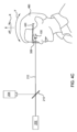
上述したように、図3A及び図3Bは、患者外デバイスと共に利用される場合の多焦点レンズ308の簡易化された模式図を示す一方、図4A~図4Cは、特定の実施形態による、検眼用フレーム440において患者によって装着されている多焦点レンズ308の簡易化された上面及び側面模式図を示す。図5は、幾つかの実施形態による、患者外デバイス又は検眼用フレーム440に結合された多焦点レンズ308を含み得る図2の視軸識別システム200を用いて視軸120の場所130を特定する方法500の流れ図を示す。したがって、図3A、図3B、及び図4A~図4Cについて、明確にするために図5と一緒に本明細書においてより詳細に説明する。
As mentioned above, FIGS. 3A and 3B show simplified schematic diagrams of a
一般に、動作510において、視軸識別システム200を使用している間、患者は多焦点レンズ308を通して見て、固視光ビーム212を注視する。患者が固視光ビーム212を固視する際、焦点F1が、患者の視野の中心が配置される中心窩122に形成される。多焦点レンズ308の第2の屈折力209も、網膜116の近くで多焦点レンズ308の光軸318に沿って第2の焦点F2を生じさせる。焦点F2は、例えば正ジオプタを有する多焦点レンズ308の第2の屈折力209による固視光ビーム212中の光線の合焦増大(例えば収束)に起因して、網膜116上に配置された焦点F1と異なる側方場所を有する。
Generally, in
焦点F1及び焦点F2は、図3A及び図4Aに示されるように視軸120に沿って位置合わせされておらず(例えば互いに重複せず、又は互いに対して並進シフトしていない)、2つの分離された(例えば位置合わせされない、重複していない)画像が患者の網膜116上に形成される。これらの状況下で、患者は固視光ビーム212によって形成される2つの「スポット」を視覚化し得る:焦点F1によって作成される第1の鮮鋭な像及び焦点F2によって作成される第2のぼやけた(例えばかすれた又は曖昧な)像。しかしながら、焦点F1及び焦点F2が図3B及び図4Bに示すように視軸120に沿って重なる場合、患者は固視光ビーム212の2つの位置合わせされた(例えば一致した、重なった)像を網膜116上に視覚化し得る。2つの像の位置合わせ、重複、又は一致は本明細書では、焦点F1及びF2によって形成された2つの像の中心が空間的に位置合わせされ、重複し、又は一致することと参照される。そのような位置合わせは、多焦点レンズ308の屈折力307、309の共通光学中心314が厳密に眼100の視軸120上にある場合に生じる。
When focal points F1 and F2 are not aligned (e.g., do not overlap or are not translationally shifted relative to each other) along the
したがって、動作520において、多焦点レンズ308及び/又は患者の頭部は、多焦点レンズ308の共通光学中心314を眼100の視軸120上に位置決めするように移動させる。図3A及び図3Bに示す例において、患者外デバイスに結合された多焦点レンズ308は、患者が固視光ビーム212への注視を連続して維持する間、視軸120上で焦点F2を焦点F1と位置合わせするように患者の頭部に対してX軸及びY軸に沿って移動し得る。代替的には、試行して、焦点F2を焦点F1と位置合わせ又は視覚的に重ねるために、患者が頭部をX軸及びY軸に沿って移動させ、固視光ビーム212への注視を連続して維持する間、多焦点レンズ308は静止している。
Thus, in
焦点F2を視軸120と位置合わせすると、患者は中心が空間的に一致した状態で2つの重なった像又はスポットを見る。互いと位置合わせされている間であっても、焦点F1によって形成される第1の像又はスポットは鮮鋭であり、焦点F2によって形成される第2の像又はスポットはいくらかぼやけている。図3Bに示すように、焦点F2は視軸120上の焦点F1と重なるとき、固視光源202の出力点(例えば固視光ビーム212の発端)を多焦点レンズ308の共通光学中心314に結ぶ線は、視軸120の厳密なX/Y位置における角膜104の前面(例えば瞳面)と交わる。
When the focal point F2 is aligned with the
これより図4A~図4Cの実施形態を参照すると、多焦点レンズ308を患者外デバイスに結合する代わりに、多焦点レンズ308は、患者によって装着された検眼用フレーム440に配置される。そのような実施形態において、患者は、検眼用フレーム440を装着し、固視光ビーム212への注視を連続して維持している間、頭部460を移動(例えば上、下、左、及び右に回転又は傾斜)させて、試行し、視軸120上で焦点F2を焦点F1と位置合わせ又は視覚的に重ね得る。
4A-4C , instead of coupling the
図4Aに示すように、患者が固視光ビーム212に注視するとき、第1の焦点F1が中心窩122に形成される。多焦点レンズ308の光学中心314は視軸120と位置合わせされていないため、多焦点レンズ308は、視軸120と重ならない光軸318に沿って眼100の眼球空間内に第2の焦点F2を形成する。図4Bにおいて、患者は、固視光ビーム212に焦点を合わせながら頭部460を移動又は回転させて、視軸120上で焦点F2を焦点F1と位置合わせし、したがって、固視光ビーム212によって形成される、中心が空間的に一致した状態で2つの像又はスポットを見る。上述したように、焦点F2は視軸120上で焦点F1と重なるとき、固視光源202を検眼用フレーム440内の多焦点レンズ308の共通光学中心314と結ぶ線は、視軸120の場所130において角膜前面と交わる。
As shown in Figure 4A, when the patient gazes at the
明確にするために、図4Cは、検眼用フレーム440内に配置された場合、多焦点レンズ308を装着した患者の側面模式図を示す。患者は、固視光ビーム212への注視を固定する際、頭部460を「イエス」(例えばY回転)移動又は「ノー」(例えばX回転)移動で回転させる。患者の眼100と多焦点レンズ308との間の距離に起因して、患者の頭部460の回転移動は、患者の眼100及び固視光ビーム212に対して多焦点レンズ308を変位させる。この変位は、図3A及び図3Bを参照して説明した多焦点レンズ308の移動と同じ効果を有する。したがって例えば、眼100と多焦点レンズ308との間の距離が12mmであり、患者が固視光ビーム212への注視を維持しながらX移動又はY移動のいずれかで頭部を5度回転させる場合、多焦点レンズ308は眼100に対して(12mm*tan(5°))=1.05mm移動する。
For clarity, FIG. 4C shows a schematic side view of a patient wearing the
患者の頭部460及び/又は多焦点レンズ308の移動と同時に、動作530において、撮像カメラ204は多焦点レンズ308及び眼100の画像又は映像を捕捉する。一般に、撮像カメラ204は、固視光ビーム212が眼100に移動する際に沿う方向から画像を捕捉する。幾つかの例において、方法500中の眼100を記録した映像は、視軸120の場所130を識別するに当たり正確性を上げ得る。多焦点レンズ308及び眼100の画像又は映像は次いで画像処理システム206に中継され、画像処理システム206は、患者の頭部及び/又は多焦点レンズ308の移動中、多焦点レンズ308の光学中心314に対する眼100の場所を特定する。上述したように、眼100のX/Y場所の特定は、眼100の強膜の脈管をランドマークとして利用することによって達成し得る。幾つかの例において、光学中心314は、撮像カメラ204及び/又は画像処理システム206による識別のために、多焦点レンズ308上で十字マーク312を用いて示される。
Concurrently with the movement of the patient's
動作540において、患者の頭部及び/又は多焦点レンズ308の移動は、患者が、2つ以上の像の中心が一致するような固視光ビーム212の重複像を見ていると報告するまで続けられる。次いで動作550において、画像処理システム206は患者の視軸120の場所130を特定する。一般に、固視光源202の出力点を多焦点レンズ308の光学中心314に結ぶ線は、患者が、中心が空間的に位置合わせされた状態で2つの像を視覚化するとき、視軸120の厳密な場所において角膜104の外面と交わり、したがって、この交点を位置特定することにより、視軸120の場所130を識別し得る。
In
幾つかの実施形態において、患者が焦点F1及びF2の視覚的重なりを報告すると、眼100及び多焦点レンズ308の単一の画像が撮像カメラ204によって収集され、撮像処理システム206によって分析される。したがって、視軸120の場所130の識別は、唯一のX、Y座標特定であり得る。他の実施形態において、患者が焦点F1及びF2の視覚的重複を維持しようとしながら、映像又は一連の画像が撮像カメラ204によって収集され、画像処理システム206によって分析される。映像又は一連の画像は5秒、10秒、15秒、20秒、25秒、又は他の任意の適した時間期間等の任意の所望の時間期間にわたって収集し得る。例えば、時間期間は約5秒~約60秒であり得、例えば約5秒~約30秒、例えば約10秒~約20秒であり得る。この時間期間中、患者は、試行し、固視光ビーム212の重複像を見るように注視を維持するように言われる。次いで画像処理システム206は映像又は一連の画像を分析して、眼100のX/Y場所に対する多焦点レンズ308の光学中心314の平均X/Y場所を特定し得、したがって、固視光ビーム212に焦点を合わせているとき、いかなる非意図的な患者の眼及び/又は頭部の移動を補償する。したがって、視軸120の場所130の識別は平均X/Y座標特定であり得る。
In some embodiments, when the patient reports visual overlap of the foci F 1 and F 2 , a single image of the
幾つかの実施形態において、固視光ビーム212は、多焦点レンズ308を通して異なる反射特性を有する2つ以上の波長又は様々な波長を含み得る。そのような実施形態において、撮像カメラ204に向かう固視光ビーム212の望ましくない反射は、視軸識別システム200の利用中、なくすか、又は大幅に低下させることができる。一例において、固視光ビーム212は、多焦点レンズ308が高反射性を有し、撮像カメラ204が感度を持たない第1の周波数を有する第1の波長を含み得る。固視光ビーム212は、多焦点レンズ308を通して高透過性を有し、眼100が感度を持たず、撮像カメラ204が高感度である第2の周波数を有する第2の波長を含むこともできる。したがって、固視光ビーム212は、第2の波長の光のみが撮像カメラ204に透過するように、多焦点レンズ308によって分離(例えば濾波)し得る。眼100及び撮像カメラ204が異なる感度を有する2つ以上の波長への固視光ビーム212のスペクトル分離は、多焦点レンズ308による反射の撹乱効果を低下させるとともに、視軸120の場所130を特定するに当たり視軸識別システム200の正確性を上げる。
In some embodiments, the
図6A~図6Dは、幾つかの実施形態による視軸識別システム200及び方法500と併用し得る交互にコーティングされた多焦点レンズ608の簡易化された模式図を示す。図7A及び図7Bは、幾つかの実施形態による、コーティング付き多焦点レンズ608を使用している間に患者の網膜116上に形成された像を示す。したがって、明確にするために、本明細書において図6A~図6D、図7A、及び図7Bについて一緒に説明する。
Figures 6A-6D show simplified schematic diagrams of an alternating coated
図6A~図6Dに示すコーティング付き多焦点レンズ608は上述した多焦点レンズ208及び308と略同様であるが、その2つの主面611a及び611bに配置されたコーティング603を含む。コーティング603は固視光ビーム212を部分的に反射し、部分的に透過する。幾つかの実施形態において、コーティング603は、固視光ビーム212をスペクトル分離させ、その光を撮像カメラ204に入射させることができる。例えば、コーティング603の反射ピーク(例えば最大反射)は、患者が視覚化する固視光ビーム212の波長に対応し得る。更なる例において、コーティング603は、撮像カメラ204によって検出される光の波長においてゼロ反射度を有し得る。したがって、撮像カメラ204に向かう固視光ビーム212の望ましくない反射は、コーティング付き多焦点レンズ608を利用することによってなくすか、又は大幅に低下させることができ、方法500中、視軸120の場所130をより正確に特定できるようにする。
6A-6D is substantially similar to the
コーティング付き多焦点レンズ608上のコーティング603の利用は、その反射性に応じて2つ以上の焦点の形成を更に可能にする。一般に、コーティング603は、無限数の焦点及び像の形成を可能にし、その強度は等比数列に従って低下する。しかしながら、人間の眼100は像を全ては知覚することができず、したがって、その限られた数のみを知覚する。形成された、知覚可能又は可視の焦点の数は、コーティング603の反射特性を変更することによって制御することができる。明確にするために、4つのみの焦点FL0、FL1、FL2、及びFL3が図6A~図6Dに示されている。固視光ビーム212が光学中心614以外の場所でコーティング付き多焦点レンズ608を透過する場合、複数の焦点FL0、FL1、FL2、及びFL3は、光軸618(図6A及び図6Cに示される)から並進シフトし、患者は非重複スポットを見る。しかしながら、固視光ビーム212がコーティング付き多焦点レンズ608の光学中心614を通り、その光軸618(図6Dに示される)と平行する場合、焦点FL0、FL1、FL2、及びFL3はコーティング付き多焦点レンズ608の光軸618上で視覚的に重なり、患者は重なったスポットを見る。
The use of
多焦点レンズ608は、多焦点レンズ208及び308並びに方法500を参照して説明したものと略同様の方法を介して、患者の眼100の視軸120を位置特定するのに利用し得る。一般に、多焦点レンズ608は、患者が固視光ビーム212に焦点を合わせているとき、患者の眼100に対してX又はY方向に並進移動する。患者が、中心が空間的に一致した重複スポットを視覚化するとき、固視光ビーム212は多焦点レンズ608の光学中心614を通して向けられており、光学中心614は厳密に眼100の視軸120上にあり、それにより、視軸120の識別を可能にする。
The
図7Aは、コーティング付き多焦点レンズ608の中心から外れた場所を通して固視光ビーム212を見ているときの患者のビューを示す。ここでは、焦点FL0、FL1、FL2、及びFL3は、光軸618及び視軸120の両方上で位置合わせされていない。患者は、サイズ及び鮮鋭度が様々なスポット715の略線形行を見る。図7Bは、固視光ビーム212がコーティング付き多焦点レンズ608の光学中心614を通るとき、患者が見得るものを示す。焦点FL0、FL1、FL2、及びFL3は、光軸618及び視軸120上で互いと視覚的に重なる。方法500中、位置合わせのために2つ以上の焦点を形成するレンズの利用により、単一焦点を形成するレンズと比較して、視軸120の場所をより精密且つ正確に特定することができる。
FIG. 7A shows the patient's view when looking at the
上述した方法及び装置は、矯正レンズのフィッティング、屈折矯正手術、人工水晶体移植、及び多焦点角膜インレーを含む老眼処置等の眼科処置の効能を改善するのに利用し得る新規の視軸識別システムを提供する。記載された視軸識別システムは、任意の適した眼科診断デバイスと組み合わせて更に利用し得る。適した診断デバイスの例には、角膜トポグラファ、光学コヒーレンストモグラフィ装置、波面計(例えば収差計)、画像誘導バイオメータ、手術用顕微鏡、及び他の画像ベースの診断デバイスがある。幾つかの例において、視軸識別システム200は、テキサス州フォートワース所在のAlcon製のCENTURION(登録商標)、INFINITI(商標)、Verion(商標)、ORA(商標)システム、LenSx(登録商標)、LuxOR(登録商標)LX3プラットフォームと組み合わせて利用し得る。幾つかの例において、視軸識別システム200は、他の製造業者によって提供される眼科プラットフォームと共に利用し得る。
The above-described methods and apparatus provide a novel visual axis identification system that may be utilized to improve the efficacy of ophthalmic procedures, such as corrective lens fitting, refractive surgery, artificial lens implants, and presbyopia treatments, including multifocal corneal inlays. The described visual axis identification system may further be utilized in combination with any suitable ophthalmic diagnostic device. Examples of suitable diagnostic devices include corneal topographers, optical coherence tomography devices, wavefront meters (e.g., aberrometers), image-guided biometers, surgical microscopes, and other image-based diagnostic devices. In some examples, the visual
実施形態例
実施形態1:患者の眼の視軸の場所を特定する方法であって、患者の眼に隣接して多焦点光学レンズを配置することであって、多焦点光学レンズは、多焦点光学レンズの光学中心に、対応する空間的に一致する光学中心を有する2つ以上の屈折力を有する、配置することと、固視光を生成し、患者の眼に向けることであって、固視光は患者の眼の網膜近くの焦点に2つ以上の像を形成し、2つ以上の像は多焦点光学レンズの2つ以上の屈折力に対応する、生成し向けることと、固視光の方向に沿って患者の眼及び多焦点光学レンズの画像を捕捉することと、多焦点光学レンズの光学中心のX/Y場所に相対する患者の眼のX/Y場所を特定することと、2つ以上の像の中心が患者のビューにおいて一致するまで、患者が固視光への注視を維持しながら、患者の眼に相対して多焦点光学レンズを移動させることと、患者の眼の瞳面における患者の眼の視軸の場所を識別することであって、視軸の場所は、固視光の方向から見た多焦点光学レンズの光学中心の場所に対応する、識別することと、
を含む、方法。
Example Embodiments Embodiment 1: A method of locating a visual axis of a patient's eye, comprising: positioning a multifocal optical lens adjacent to the patient's eye, the multifocal optical lens having two or more refractive powers with corresponding spatially coincident optical centers at an optical center of the multifocal optical lens; generating and directing a fixation light to the patient's eye, the fixation light forming two or more images at a focal point near the retina of the patient's eye, the two or more images corresponding to the two or more refractive powers of the multifocal optical lens; capturing an image of the patient's eye and the multifocal optical lens along the direction of the fixation light; identifying an X/Y location of the patient's eye relative to an X/Y location of the optical center of the multifocal optical lens; moving the multifocal optical lens relative to the patient's eye while the patient maintains gaze on the fixation light until the centers of the two or more images are coincident in the patient's view; and identifying a location of the visual axis of the patient's eye in a pupil plane of the patient's eye, the location of the visual axis corresponding to a location of the optical center of the multifocal optical lens as viewed from the direction of the fixation light.
A method comprising:
実施形態2:多焦点光学レンズは患者によって装着される検眼用フレームに結合される、実施形態1に記載の方法。 Embodiment 2: The method of embodiment 1, wherein the multifocal optical lens is coupled to an eye trial frame worn by the patient.
実施形態3:多焦点光学レンズは患者外デバイスに結合される、実施形態1に記載の方法。 Embodiment 3: The method of embodiment 1, wherein the multifocal optical lens is coupled to a patient-external device.
実施形態4:患者の眼の視軸の場所を特定するシステムであって、多焦点光学レンズと、眼の移動を追跡するように構成された検出器であって、検出器は、眼の場所に対する多焦点光学レンズの画像を捕捉するように更に構成される、検出器と、検出器によって捕捉された画像に基づいて、眼の前面における眼の視軸の場所を識別するように構成される処理システムであって、眼の視軸は、多焦点光学レンズの2つ以上の焦点の中心が患者のビューにおいて一致するときの多焦点光学レンズの光学中心に対応する、処理システムとを備える、システム。 Embodiment 4: A system for determining a location of a visual axis of a patient's eye, comprising: a multifocal optical lens; a detector configured to track eye movements, the detector further configured to capture an image of the multifocal optical lens relative to a location of the eye; and a processing system configured to identify a location of the visual axis of the eye at a front surface of the eye based on the image captured by the detector, the visual axis of the eye corresponding to an optical center of the multifocal optical lens when the centers of two or more foci of the multifocal optical lens coincide in the patient's view.
実施形態5:多焦点光学レンズは検眼用フレームに結合される、実施形態4に記載のシステム。 Embodiment 5: The system described in embodiment 4, wherein the multifocal optical lens is coupled to an eye trial frame.
実施形態6:多焦点光学レンズは患者外デバイスに結合される、実施形態4に記載のシステム。 Embodiment 6: The system of embodiment 4, wherein the multifocal optical lens is coupled to a patient-external device.
実施形態7:検出器は赤外線カメラである、実施形態4に記載のシステム。 Embodiment 7: The system of embodiment 4, wherein the detector is an infrared camera.
実施形態8:赤外線カメラは、眼の強膜の脈管のランドマークを検出することによって眼の移動を追跡するように構成される、実施形態7に記載のシステム。 Embodiment 8: The system of embodiment 7, wherein the infrared camera is configured to track eye movement by detecting vascular landmarks in the sclera of the eye.
実施形態9:多焦点光学レンズはアキシコンを含む、実施形態4に記載のシステム。 Embodiment 9: The system of embodiment 4, wherein the multifocal optical lens includes an axicon.
上記は本開示の実施形態に関するが、その基本的な範囲から逸脱せずに本開示の他の及び更なる実施形態が考案され得、その範囲は以下の特許請求の範囲によって決定される。 態様(1)によれば、患者の眼の視軸の場所を特定する方法であって、
前記患者の眼に隣接して多焦点光学レンズを配置することであって、前記多焦点光学レンズは、前記多焦点光学レンズの光学中心に、対応する空間的に一致する光学中心を有する2つ以上の屈折力を有する、配置することと、
固視光を生成し、前記患者の眼に向けることであって、前記固視光は前記患者の眼の網膜近くの焦点に2つ以上の像を形成し、前記2つ以上の像は前記多焦点光学レンズの前記2つ以上の屈折力に対応する、生成し向けることと、
前記固視光の方向に沿って前記患者の眼及び前記多焦点光学レンズの画像を捕捉することと、
前記多焦点光学レンズの前記光学中心のX/Y場所に相対する前記患者の眼のX/Y場所を特定することと、
前記2つ以上の像の中心が前記患者のビューにおいて一致するまで、前記患者が前記固視光への注視を維持しながら、前記患者の眼に相対して前記多焦点光学レンズを移動させることと、
前記患者の眼の瞳面における前記患者の眼の前記視軸の前記場所を識別することであって、前記視軸の前記場所は、前記固視光の前記方向から見た前記多焦点光学レンズの前記光学中心の場所に対応する、識別することと、
を含む、方法である。
態様(2)によれば、前記多焦点光学レンズは、その2つ以上の表面に光学コーティングを有する。
態様(3)によれば、前記多焦点光学レンズは、前記患者の眼内に3つ以上の焦点を形成するように構成される。
態様(4)によれば、前記視軸の前記場所は、前記2つ以上の像の前記中心が前記患者の前記ビューにおいて互いと一致する場合、前記多焦点光学レンズの前記光学中心の前記場所に更に対応する。
態様(5)によれば、前記固視光のスペクトルは、前記多焦点光学レンズを通して異なる屈折特性及び反射特性を有する2つ以上の波長範囲に分離する。
態様(6)によれば、前記多焦点光学レンズの前記光学中心は、十字マークによって記される。
態様(7)によれば、前記患者の眼の前記視軸の前記場所を識別することは、
前記患者が、前記固視光によって形成された一致像を見るように注視を前記固視光に維持している時間期間中、前記患者の眼の前記場所に対する前記多焦点光学レンズの前記光学中心のX/Y場所を空間的に平均することを更に含む。
態様(8)によれば、前記時間期間は約5秒~約60秒である。
態様(9)によれば、前記多焦点光学レンズは、超長焦線を形成するように構成された複雑な回折光学要素である。
態様(10)によれば、前記多焦点光学レンズはアキシコンを含む。
態様(11)によれば、前記多焦点光学レンズは、非球面拡張焦点深度レンズを含む。
態様(12)によれば、患者の眼の視軸の場所を特定するシステムであって、
多焦点光学レンズと、
前記眼の移動を追跡するように構成された検出器であって、前記検出器は、前記眼の場所に対する前記多焦点光学レンズの画像を捕捉するように更に構成される、検出器と、
前記検出器によって捕捉された前記画像に基づいて、前記眼の前面における前記眼の前記視軸の前記場所を識別するように構成される処理システムであって、前記眼の前記視軸は、前記多焦点光学レンズの2つ以上の焦点の中心が前記患者のビューにおける像と一致し、重複像を形成するとき、前記多焦点光学レンズの光学中心に対応する、処理システムと、
を備える、システムである。
態様(13)によれば、前記多焦点光学レンズは、超長焦線を形成するように構成された複雑な回折光学要素である。
態様(14)によれば、前記多焦点光学レンズは、非球面拡張焦点深度レンズを含む。
態様(15)によれば、前記眼の前記視軸の前記場所を識別するように構成された前記処理システムは、
患者が、固視光によって形成された重複像を見るように注視を前記固視光に維持している時間期間中、前記眼の前記場所に対する前記多焦点光学レンズの前記光学中心のX/Y場所を平均するように構成される前記処理システムを含む。
While the above relates to embodiments of the present disclosure, other and further embodiments of the present disclosure may be devised without departing from the basic scope thereof, which scope is determined by the following claims. According to aspect (1), there is provided a method for locating a visual axis of a patient's eye, comprising:
placing a multifocal optical lens adjacent to the patient's eye, the multifocal optical lens having two or more optical powers with corresponding spatially coincident optical centers at an optical center of the multifocal optical lens;
generating and directing a fixation light to the patient's eye, the fixation light forming two or more images at a focal point near the retina of the patient's eye, the two or more images corresponding to the two or more refractive powers of the multifocal optical lens;
capturing an image of the patient's eye and the multifocal optical lens along a direction of the fixation light;
Identifying an X/Y location of the patient's eye relative to an X/Y location of the optical center of the multifocal optical lens;
moving the multifocal optical lens relative to the patient's eye while the patient maintains gaze on the fixation light until the centers of the two or more images coincide in the patient's view;
identifying the location of the visual axis of the patient's eye at a pupil plane of the patient's eye, the location of the visual axis corresponding to a location of the optical center of the multifocal optical lens as viewed from the direction of the fixation light;
The method includes:
According to aspect (2), the multifocal optical lens has an optical coating on two or more surfaces thereof.
According to aspect (3), the multifocal optical lens is configured to form three or more focal points in the patient's eye.
According to aspect (4), the location of the visual axis further corresponds to the location of the optical center of the multifocal optical lens when the centers of the two or more images coincide with each other in the view of the patient.
According to aspect (5), the spectrum of the fixation light is separated into two or more wavelength ranges having different refractive and reflective properties through the multifocal optical lens.
According to aspect (6), the optical center of the multifocal optical lens is marked by a cross mark.
According to aspect (7), identifying the location of the visual axis of the patient's eye comprises:
The method further includes spatially averaging the X/Y location of the optical center of the multifocal optical lens relative to the location of the patient's eye during a period of time when the patient maintains gaze on the fixation light so as to view a coincident image formed by the fixation light.
According to aspect (8), the time period is from about 5 seconds to about 60 seconds.
According to aspect (9), the multifocal optical lens is a complex diffractive optical element configured to form an ultra-long focal line.
According to aspect (10), the multifocal optical lens includes an axicon.
According to aspect (11), the multifocal optical lens includes an aspheric extended depth of focus lens.
According to aspect (12), there is provided a system for determining a location of a visual axis of an eye of a patient, the system comprising:
A multifocal optical lens;
a detector configured to track movement of the eye, the detector further configured to capture an image of the multifocal optical lens relative to a location of the eye;
a processing system configured to identify the location of the visual axis of the eye at the front surface of the eye based on the image captured by the detector, the visual axis of the eye corresponding to an optical center of the multifocal optical lens when centers of two or more foci of the multifocal optical lens coincide with an image in the patient's view and form an overlapping image;
The system includes:
According to aspect (13), the multifocal optical lens is a complex diffractive optical element configured to form an ultra-long focal line.
According to aspect (14), the multifocal optical lens includes an aspheric extended depth of focus lens.
According to aspect (15), the processing system configured to identify the location of the visual axis of the eye comprises:
The processing system is configured to average the X/Y location of the optical center of the multifocal optical lens relative to the location of the eye during a period of time when the patient maintains gaze on the fixation light so as to view an overlapping image formed by the fixation light.
Claims (4)
多焦点光学レンズと、
前記眼の移動を追跡するように構成された検出器であって、前記検出器は、前記眼の場所に対する前記多焦点光学レンズの画像を捕捉するように更に構成される、前記検出器と、
前記検出器によって捕捉された前記画像に基づいて、前記眼の前面における前記眼の前記視軸の前記場所を識別するように構成される処理システムであって、前記患者が、前記多焦点光学レンズの2つ以上の焦点の中心が前記患者のビューにおける像と一致するような重複像を見ていると報告したときに、前記視軸の前記場所が識別される、処理システムと、
を備える、システム。 1. A system for locating a visual axis of a patient's eye, comprising:
A multifocal optical lens;
a detector configured to track movement of the eye, the detector further configured to capture an image of the multifocal optical lens relative to a location of the eye ;
a processing system configured to identify the location of the visual axis of the eye at the front surface of the eye based on the image captured by the detector, the location of the visual axis being identified when the patient reports seeing overlapping images such that the centers of two or more foci of the multifocal optical lens coincide with an image in the patient's view;
A system comprising:
前記患者が、固視光によって形成された重複像を見るように注視を前記固視光に維持している時間期間中、前記眼の前記場所に対する前記多焦点光学レンズの光学中心のX/Y場所を平均するように構成される前記処理システムを含む、請求項1に記載のシステム。 The processing system configured to identify the location of the visual axis of the eye,
The system of claim 1 , further comprising a processing system configured to average the X/Y location of the optical center of the multifocal optical lens relative to the location of the eye during a period of time when the patient maintains gaze on the fixation light so as to view an overlapping image formed by the fixation light.
Applications Claiming Priority (3)
| Application Number | Priority Date | Filing Date | Title |
|---|---|---|---|
| US202063010293P | 2020-04-15 | 2020-04-15 | |
| US63/010,293 | 2020-04-15 | ||
| PCT/IB2021/052923 WO2021209866A1 (en) | 2020-04-15 | 2021-04-08 | System and methods for identification of the human visual axis |
Publications (2)
| Publication Number | Publication Date |
|---|---|
| JP2023521855A JP2023521855A (en) | 2023-05-25 |
| JP7692000B2 true JP7692000B2 (en) | 2025-06-12 |
Family
ID=75539721
Family Applications (1)
| Application Number | Title | Priority Date | Filing Date |
|---|---|---|---|
| JP2022562383A Active JP7692000B2 (en) | 2020-04-15 | 2021-04-08 | System and method for identifying human visual axis |
Country Status (8)
| Country | Link |
|---|---|
| US (1) | US11950845B2 (en) |
| EP (1) | EP4135562B1 (en) |
| JP (1) | JP7692000B2 (en) |
| CN (1) | CN115397307B (en) |
| AU (1) | AU2021254864A1 (en) |
| CA (1) | CA3169531A1 (en) |
| ES (1) | ES3057543T3 (en) |
| WO (1) | WO2021209866A1 (en) |
Families Citing this family (5)
| Publication number | Priority date | Publication date | Assignee | Title |
|---|---|---|---|---|
| US12403038B2 (en) | 2020-12-16 | 2025-09-02 | Alcon Inc. | Systems and methods for creating a lenticule for presbyopia |
| EP4262652A1 (en) | 2020-12-19 | 2023-10-25 | Alcon Inc. | Ablation systems and methods for treating presbyopia |
| DE102021125627A1 (en) * | 2021-10-04 | 2023-04-06 | OSRAM Opto Semiconductors Gesellschaft mit beschränkter Haftung | COMPONENT FOR DATA GLASSES AND DATA GLASSES |
| KR102792731B1 (en) * | 2022-07-18 | 2025-04-11 | 한양대학교 산학협력단 | Multi-focal lens with central axicon zone |
| DE102022134615A1 (en) * | 2022-12-22 | 2024-06-27 | Schwind Eye-Tech-Solutions Gmbh | Centering device for determining a centering of a visual axis of an eye |
Citations (4)
| Publication number | Priority date | Publication date | Assignee | Title |
|---|---|---|---|---|
| JP2003245300A (en) | 2002-02-27 | 2003-09-02 | Nidek Co Ltd | Ophthalmic equipment |
| US20070285620A1 (en) | 2006-06-09 | 2007-12-13 | Clark Thomas H | Visual axis and alignment measurement system and method of using same |
| JP2018033717A (en) | 2016-08-31 | 2018-03-08 | 株式会社トプコン | Ophthalmological device |
| WO2018178493A2 (en) | 2017-03-30 | 2018-10-04 | Merindades Vision S.L. | Method for designing a pair of ophthalmic lenses and device for optical measurements |
Family Cites Families (10)
| Publication number | Priority date | Publication date | Assignee | Title |
|---|---|---|---|---|
| US5237351A (en) * | 1989-06-23 | 1993-08-17 | Canon Kabushiki Kaisha | Visual target apparatus |
| US5046257A (en) * | 1990-01-19 | 1991-09-10 | Marshall Forrest A | Determining and marking apparatus and method for use in optometry and ophthalmology |
| US6036316A (en) * | 1996-10-02 | 2000-03-14 | Canon Kabushiki Kaisha | Visual axis detecting device and apparatus including visual axis detecting device |
| US7431455B2 (en) * | 2005-03-22 | 2008-10-07 | Amo Manufacturing Usa, Llc | Pupilometer for pupil center drift and pupil size measurements at differing viewing distances |
| US8342688B1 (en) * | 2009-06-15 | 2013-01-01 | Casimir Andrew Swinger | Multifocal capable ophthalmic aberrometer |
| WO2011008609A1 (en) * | 2009-07-14 | 2011-01-20 | Wavetec Vision Systems, Inc. | Ophthalmic surgery measurement system |
| JP2011250981A (en) * | 2010-06-02 | 2011-12-15 | Hoya Corp | Multifocal lens simulator |
| FR2984717B1 (en) * | 2011-12-22 | 2014-02-28 | Essilor Int | DEVICE FOR DETERMINING AT LEAST ONE VISION PARAMETER OF A SUBJECT FOLLOWING A PLURALITY OF VISEE DIRECTION |
| CN102551654B (en) * | 2012-01-20 | 2013-09-18 | 王毅 | Optical coherence biological measurer and method for biologically measuring eyes |
| EP3465545A4 (en) * | 2016-06-01 | 2020-01-29 | Vidi Pty Ltd | OPTICAL MEASURING AND SCANING SYSTEM AND METHOD FOR USE |
-
2021
- 2021-04-08 JP JP2022562383A patent/JP7692000B2/en active Active
- 2021-04-08 CN CN202180028695.2A patent/CN115397307B/en active Active
- 2021-04-08 AU AU2021254864A patent/AU2021254864A1/en active Pending
- 2021-04-08 US US17/225,217 patent/US11950845B2/en active Active
- 2021-04-08 WO PCT/IB2021/052923 patent/WO2021209866A1/en not_active Ceased
- 2021-04-08 EP EP21719271.5A patent/EP4135562B1/en active Active
- 2021-04-08 CA CA3169531A patent/CA3169531A1/en active Pending
- 2021-04-08 ES ES21719271T patent/ES3057543T3/en active Active
Patent Citations (4)
| Publication number | Priority date | Publication date | Assignee | Title |
|---|---|---|---|---|
| JP2003245300A (en) | 2002-02-27 | 2003-09-02 | Nidek Co Ltd | Ophthalmic equipment |
| US20070285620A1 (en) | 2006-06-09 | 2007-12-13 | Clark Thomas H | Visual axis and alignment measurement system and method of using same |
| JP2018033717A (en) | 2016-08-31 | 2018-03-08 | 株式会社トプコン | Ophthalmological device |
| WO2018178493A2 (en) | 2017-03-30 | 2018-10-04 | Merindades Vision S.L. | Method for designing a pair of ophthalmic lenses and device for optical measurements |
Also Published As
| Publication number | Publication date |
|---|---|
| AU2021254864A1 (en) | 2022-09-22 |
| EP4135562A1 (en) | 2023-02-22 |
| US20210321869A1 (en) | 2021-10-21 |
| CA3169531A1 (en) | 2021-10-21 |
| EP4135562B1 (en) | 2025-10-01 |
| ES3057543T3 (en) | 2026-03-03 |
| JP2023521855A (en) | 2023-05-25 |
| CN115397307A (en) | 2022-11-25 |
| CN115397307B (en) | 2026-04-21 |
| US11950845B2 (en) | 2024-04-09 |
| WO2021209866A1 (en) | 2021-10-21 |
Similar Documents
| Publication | Publication Date | Title |
|---|---|---|
| JP7692000B2 (en) | System and method for identifying human visual axis | |
| US6033075A (en) | Ophthalmic apparatus | |
| US7252661B2 (en) | Method and system for patient optical fixation | |
| US6139145A (en) | Ophthalmic optical element incorporating a holographic element and use of same in cases of central field loss | |
| US5474548A (en) | Method of establishing a unique machine independent reference frame for the eye | |
| US12150709B2 (en) | Visual axis identification systems and methods | |
| JP5162458B2 (en) | Ophthalmic surgery microscope with measuring device | |
| CN109068973B (en) | Keratometer with detachable micro microscope for cataract operation | |
| US10314482B2 (en) | Eye alignment monitor and method | |
| US11284793B2 (en) | Method and device for determining the orientation of the eye during eye surgeries | |
| US20030216763A1 (en) | Method of determining the visual axis of an eye | |
| US20150011984A1 (en) | Corneal visual center localizer (or locator) | |
| ITRM20070183A1 (en) | OPHTHALMOLOGICAL MULTIFUNCTION APPARATUS. | |
| JP4663147B2 (en) | Eye characteristics measuring device | |
| JP4551107B2 (en) | Optical system alignment apparatus and method, and three-dimensional observation state measurement apparatus and method using the same | |
| JP7350992B2 (en) | Joint identification of accommodation and congestion | |
| US12446772B2 (en) | Methods and system to identify position, rotation, and tilt of a contact lens on an eye | |
| EP4516204A1 (en) | Ophthalmic examination apparatus and ophthalmic examination method | |
| Deshmukh et al. | Corneal Topography | |
| Lee | Refraction and Glasses Exam | |
| HK40000130A (en) | Detachable miniature microscope mounted keratometer for cataract surgery |
Legal Events
| Date | Code | Title | Description |
|---|---|---|---|
| A621 | Written request for application examination |
Free format text: JAPANESE INTERMEDIATE CODE: A621 Effective date: 20240329 |
|
| A977 | Report on retrieval |
Free format text: JAPANESE INTERMEDIATE CODE: A971007 Effective date: 20241113 |
|
| A131 | Notification of reasons for refusal |
Free format text: JAPANESE INTERMEDIATE CODE: A131 Effective date: 20241119 |
|
| A521 | Request for written amendment filed |
Free format text: JAPANESE INTERMEDIATE CODE: A523 Effective date: 20250213 |
|
| TRDD | Decision of grant or rejection written | ||
| A01 | Written decision to grant a patent or to grant a registration (utility model) |
Free format text: JAPANESE INTERMEDIATE CODE: A01 Effective date: 20250513 |
|
| A61 | First payment of annual fees (during grant procedure) |
Free format text: JAPANESE INTERMEDIATE CODE: A61 Effective date: 20250602 |
|
| R150 | Certificate of patent or registration of utility model |
Ref document number: 7692000 Country of ref document: JP Free format text: JAPANESE INTERMEDIATE CODE: R150 |