JPWO2006123738A1 - Dc/dcコンバータ - Google Patents
Dc/dcコンバータ Download PDFInfo
- Publication number
- JPWO2006123738A1 JPWO2006123738A1 JP2006526883A JP2006526883A JPWO2006123738A1 JP WO2006123738 A1 JPWO2006123738 A1 JP WO2006123738A1 JP 2006526883 A JP2006526883 A JP 2006526883A JP 2006526883 A JP2006526883 A JP 2006526883A JP WO2006123738 A1 JPWO2006123738 A1 JP WO2006123738A1
- Authority
- JP
- Japan
- Prior art keywords
- switching element
- converter
- switching means
- voltage
- time
- Prior art date
- Legal status (The legal status is an assumption and is not a legal conclusion. Google has not performed a legal analysis and makes no representation as to the accuracy of the status listed.)
- Granted
Links
Images

Classifications
-
- H—ELECTRICITY
- H02—GENERATION; CONVERSION OR DISTRIBUTION OF ELECTRIC POWER
- H02M—APPARATUS FOR CONVERSION BETWEEN AC AND AC, BETWEEN AC AND DC, OR BETWEEN DC AND DC, AND FOR USE WITH MAINS OR SIMILAR POWER SUPPLY SYSTEMS; CONVERSION OF DC OR AC INPUT POWER INTO SURGE OUTPUT POWER; CONTROL OR REGULATION THEREOF
- H02M3/00—Conversion of DC power input into DC power output
- H02M3/02—Conversion of DC power input into DC power output without intermediate conversion into AC
- H02M3/04—Conversion of DC power input into DC power output without intermediate conversion into AC by static converters
- H02M3/10—Conversion of DC power input into DC power output without intermediate conversion into AC by static converters using discharge tubes with control electrode or semiconductor devices with control electrode
- H02M3/145—Conversion of DC power input into DC power output without intermediate conversion into AC by static converters using discharge tubes with control electrode or semiconductor devices with control electrode using devices of a triode or transistor type requiring continuous application of a control signal
- H02M3/155—Conversion of DC power input into DC power output without intermediate conversion into AC by static converters using discharge tubes with control electrode or semiconductor devices with control electrode using devices of a triode or transistor type requiring continuous application of a control signal using semiconductor devices only
- H02M3/156—Conversion of DC power input into DC power output without intermediate conversion into AC by static converters using discharge tubes with control electrode or semiconductor devices with control electrode using devices of a triode or transistor type requiring continuous application of a control signal using semiconductor devices only with automatic control of output voltage or current, e.g. switching regulators
- H02M3/158—Conversion of DC power input into DC power output without intermediate conversion into AC by static converters using discharge tubes with control electrode or semiconductor devices with control electrode using devices of a triode or transistor type requiring continuous application of a control signal using semiconductor devices only with automatic control of output voltage or current, e.g. switching regulators including plural semiconductor devices as final control devices for a single load
- H02M3/1588—Conversion of DC power input into DC power output without intermediate conversion into AC by static converters using discharge tubes with control electrode or semiconductor devices with control electrode using devices of a triode or transistor type requiring continuous application of a control signal using semiconductor devices only with automatic control of output voltage or current, e.g. switching regulators including plural semiconductor devices as final control devices for a single load comprising at least one synchronous rectifier element
-
- H—ELECTRICITY
- H02—GENERATION; CONVERSION OR DISTRIBUTION OF ELECTRIC POWER
- H02M—APPARATUS FOR CONVERSION BETWEEN AC AND AC, BETWEEN AC AND DC, OR BETWEEN DC AND DC, AND FOR USE WITH MAINS OR SIMILAR POWER SUPPLY SYSTEMS; CONVERSION OF DC OR AC INPUT POWER INTO SURGE OUTPUT POWER; CONTROL OR REGULATION THEREOF
- H02M3/00—Conversion of DC power input into DC power output
- H02M3/02—Conversion of DC power input into DC power output without intermediate conversion into AC
- H02M3/04—Conversion of DC power input into DC power output without intermediate conversion into AC by static converters
- H02M3/10—Conversion of DC power input into DC power output without intermediate conversion into AC by static converters using discharge tubes with control electrode or semiconductor devices with control electrode
- H02M3/145—Conversion of DC power input into DC power output without intermediate conversion into AC by static converters using discharge tubes with control electrode or semiconductor devices with control electrode using devices of a triode or transistor type requiring continuous application of a control signal
- H02M3/155—Conversion of DC power input into DC power output without intermediate conversion into AC by static converters using discharge tubes with control electrode or semiconductor devices with control electrode using devices of a triode or transistor type requiring continuous application of a control signal using semiconductor devices only
-
- Y—GENERAL TAGGING OF NEW TECHNOLOGICAL DEVELOPMENTS; GENERAL TAGGING OF CROSS-SECTIONAL TECHNOLOGIES SPANNING OVER SEVERAL SECTIONS OF THE IPC; TECHNICAL SUBJECTS COVERED BY FORMER USPC CROSS-REFERENCE ART COLLECTIONS [XRACs] AND DIGESTS
- Y02—TECHNOLOGIES OR APPLICATIONS FOR MITIGATION OR ADAPTATION AGAINST CLIMATE CHANGE
- Y02B—CLIMATE CHANGE MITIGATION TECHNOLOGIES RELATED TO BUILDINGS, e.g. HOUSING, HOUSE APPLIANCES OR RELATED END-USER APPLICATIONS
- Y02B70/00—Technologies for an efficient end-user side electric power management and consumption
- Y02B70/10—Technologies improving the efficiency by using switched-mode power supplies [SMPS], i.e. efficient power electronics conversion e.g. power factor correction or reduction of losses in power supplies or efficient standby modes
Landscapes
- Engineering & Computer Science (AREA)
- Power Engineering (AREA)
- Dc-Dc Converters (AREA)
Abstract
Description
前記コイルにエネルギを蓄積する際にオンするスイッチング手段を主スイッチング手段とする一方、前記コイルに蓄積したエネルギを出力側へ送出する際にオンするスイッチング手段を従スイッチング手段とするとき、前記従スイッチング手段がオフしてから前記両スイッチング手段の接続点の電圧が所定の閾値に達するまでの時間に基づき後の周期における前記従スイッチング手段のオン時間を制御するように構成した制御手段を有すること。
前記制御手段は、前記コイルを流れる電流の極性が反転しないように後の周期における前記従スイッチング手段のオン時間を制御するように構成したこと。
次の周期における前記従スイッチング手段のオフ時間は、前記従スイッチング手段がオフしてから前記両スイッチング手段の接続点の電圧が所定の閾値に達するまでの間に容量に蓄積した電位に基づき制御すること。
前記容量に蓄積した電位は、各周期毎に前記従スイッチング手段のオフに先立ち所定値だけ電位を制御すること。
降圧コンバータ又は昇圧コンバータの何れかであること。
前記制御部が、前記主スイッチング手段のスイッチングパルスを得るため、PWM方式、PFM方式又はPWM方式とPFM方式との双方の何れかを採用するものであること。
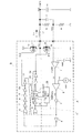
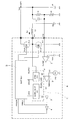
S2,S12 従スイッチング素子
C0 平滑コンデンサ
L1 コイル
A PWM信号発生部
B バッファ部
C スイッチング信号制御部
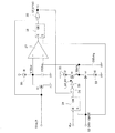
1 誤差増幅器
2,17 比較器
15 1ショットブロック
16 シンクブロック
18,19 RSフリップフロップ
20,21,22 定電流源
I1,I2,I3 定電流
S3,S4 スイッチング素子
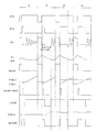
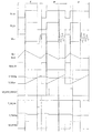
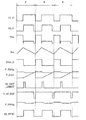
S1_G,S11_G スイッチングパルス
S2_G,S12_G スイッチングパルス
VLx 電圧信号
ILx コイル電流
S2on_B スイッチングパルス
V_2chg,V_2on 電圧
S2_DRV_1SHOT 1ショットパルス
T_S2_DIF パルス信号
S2_SYNC パルス信号
ΔV_S2chg = I2 × tdif / CS2chg ・・・(2)
式(1)と式(2)から
ΔTsync = CS2on / I1 × I2 / CS2chg ×tdif ・・・ (3)
ここで、例えば、I1=I2 、 CS2on=CS2chg とすればΔTsync = tdif となる。同様関係は、I1:I2=n:1のときCS2on:CS2chg=1:nの関係が成立していれば一般に成立する。
= CS2on×(ΔV_S2chg I3*S2_DRV_1SHOT/CS2chg)/I1 ・・・(4)
ΔV_S2chg = I2 × tdif / CS2chg ・・・(5)
上式(4)、(5)から
ΔTsync = CS2on × (I2 × tdif / CS2chg I3*S2_DRV_1SHOT / CS2chg) / I1 ・・・(6)
ここで、例えばI1=I2=I3、CS2on=CS2chg とすれば
ΔTsync = tdif S2_DRV_1SHOTとなる。
Claims (6)
- 直列に接続した2つのスイッチング手段と、両スイッチング手段の接続点に接続したコイルとを備えて直流入力電圧を所定の直流出力電圧に変換するとともに前記コイルを介して負荷に電力を供給するDC/DCコンバータにおいて、
前記コイルにエネルギを蓄積する際にオンするスイッチング手段を主スイッチング手段とする一方、前記コイルに蓄積したエネルギを出力側へ送出する際にオンするスイッチング手段を従スイッチング手段とするとき、前記従スイッチング手段がオフしてから前記両スイッチング手段の接続点の電圧が所定の閾値に達するまでの時間に基づき後の周期における前記従スイッチング手段のオン時間を制御するように構成した制御手段を有することを特徴とするDC/DCコンバータ。 - 請求項1において、
前記制御手段は、前記コイルを流れる電流の極性が反転しないように後の周期における前記従スイッチング手段のオン時間を制御するように構成したことを特徴とするDC/DCコンバータ。 - 請求項1又は請求項2において、
次の周期における前記従スイッチング手段のオフ時間は、前記従スイッチング手段がオフしてから前記両スイッチング手段の接続点の電圧が所定の閾値に達するまでの間に容量に蓄積した電位に基づき制御することを特徴とするDC/DCコンバータ。 - 請求項3において、
前記容量に蓄積した電位は、各周期毎に前記従スイッチング手段のオフに先立ち所定値だけ電位を制御することを特徴とするDC/DCコンバータ。 - 請求項1乃至請求項4の何れかのDC/DCコンバータは、
降圧コンバータ又は昇圧コンバータの何れかであることを特徴とするDC/DCコンバータ。 - 請求項1乃至請求項4の何れかのDC/DCコンバータは、
前記制御部が、前記主スイッチング手段のスイッチングパルスを得るため、PWM方式、PFM方式又はPWM方式とPFM方式との双方の何れかを採用するものであることを特徴とするDC/DCコンバータ。
Applications Claiming Priority (3)
| Application Number | Priority Date | Filing Date | Title |
|---|---|---|---|
| JP2005147816 | 2005-05-20 | ||
| JP2005147816 | 2005-05-20 | ||
| PCT/JP2006/309928 WO2006123738A1 (ja) | 2005-05-20 | 2006-05-18 | Dc/dcコンバータ |
Publications (2)
| Publication Number | Publication Date |
|---|---|
| JPWO2006123738A1 true JPWO2006123738A1 (ja) | 2008-12-25 |
| JP4674661B2 JP4674661B2 (ja) | 2011-04-20 |
Family
ID=37431310
Family Applications (1)
| Application Number | Title | Priority Date | Filing Date |
|---|---|---|---|
| JP2006526883A Active JP4674661B2 (ja) | 2005-05-20 | 2006-05-18 | Dc/dcコンバータ |
Country Status (7)
| Country | Link |
|---|---|
| US (1) | US7675276B2 (ja) |
| JP (1) | JP4674661B2 (ja) |
| KR (1) | KR100975352B1 (ja) |
| CN (1) | CN100559689C (ja) |
| GB (1) | GB2441926B (ja) |
| TW (1) | TWI352490B (ja) |
| WO (1) | WO2006123738A1 (ja) |
Families Citing this family (14)
| Publication number | Priority date | Publication date | Assignee | Title |
|---|---|---|---|---|
| JP4855887B2 (ja) * | 2006-10-03 | 2012-01-18 | トレックス・セミコンダクター株式会社 | Pwm/pfm制御回路及びスイッチング電源回路 |
| JP2008274756A (ja) * | 2007-04-25 | 2008-11-13 | Sanden Corp | 可変容量圧縮機の制御装置 |
| EP2104213B1 (fr) * | 2008-03-19 | 2012-05-30 | The Swatch Group Research and Development Ltd. | Procédé d'asservissement d'un convertisseur DC-DC en mode discontinu |
| TWI394363B (zh) * | 2009-09-30 | 2013-04-21 | Anpec Electronics Corp | 可降低電磁干擾之輸出驅動電路 |
| US8866467B1 (en) | 2009-10-05 | 2014-10-21 | Adaptive Digital Power, Inc. | Systems and methods to perform integrated power measurement and RDSon measurement |
| JP5578861B2 (ja) * | 2010-01-18 | 2014-08-27 | トレックス・セミコンダクター株式会社 | スイッチング電源回路 |
| JP5676961B2 (ja) | 2010-07-30 | 2015-02-25 | スパンション エルエルシー | 電源の制御回路、電子機器及び電源の制御方法 |
| DE112011103253T5 (de) * | 2010-09-28 | 2013-08-14 | Murata Manufacturing Co., Ltd. | DC/DC-Wandler |
| TWI419447B (zh) * | 2011-01-27 | 2013-12-11 | Holtek Semiconductor Inc | 電源轉換器及其功率電晶體的閘極驅動器 |
| US9340353B2 (en) * | 2012-09-27 | 2016-05-17 | Oren Technologies, Llc | Methods and systems to transfer proppant for fracking with reduced risk of production and release of silica dust at a well site |
| JP2016136793A (ja) * | 2013-05-14 | 2016-07-28 | シャープ株式会社 | スイッチング電源装置と、それを用いたインバータ、コンバータ、およびソーラーパワーコントローラ |
| JP6209022B2 (ja) * | 2013-08-27 | 2017-10-04 | リコー電子デバイス株式会社 | スイッチングレギュレータ |
| JP7061330B1 (ja) * | 2021-10-21 | 2022-04-28 | トレックス・セミコンダクター株式会社 | Dc・dcコンバータ |
| TWI905039B (zh) * | 2025-03-05 | 2025-11-11 | 華碩電腦股份有限公司 | 供電電路 |
Citations (5)
| Publication number | Priority date | Publication date | Assignee | Title |
|---|---|---|---|---|
| JPH1189222A (ja) * | 1997-09-03 | 1999-03-30 | Hitachi Ltd | 電圧変換回路 |
| JP2002281743A (ja) * | 2001-03-19 | 2002-09-27 | Hitachi Ltd | 半導体集積回路および携帯用電子機器 |
| JP2002369516A (ja) * | 2001-06-04 | 2002-12-20 | Tdk Corp | スイッチング電源装置 |
| JP2004056983A (ja) * | 2002-07-24 | 2004-02-19 | Seiko Epson Corp | 電源回路 |
| JP2005094994A (ja) * | 2003-09-15 | 2005-04-07 | Semiconductor Components Industries Llc | Dc−dcコンバータにおける電力効率を最適化する方法および回路 |
Family Cites Families (7)
| Publication number | Priority date | Publication date | Assignee | Title |
|---|---|---|---|---|
| JP2555245B2 (ja) | 1992-04-10 | 1996-11-20 | 三菱電機株式会社 | 光磁気記録媒体およびその製法 |
| US6127814A (en) * | 1998-11-23 | 2000-10-03 | Switch Power, Inc. | System to protect switch mode DC/DC converters against overload current |
| US6441597B1 (en) * | 2001-10-31 | 2002-08-27 | Semtech Corporation | Method and apparatus for sensing output inductor current in a DC-to-DC power converter |
| JP4337469B2 (ja) * | 2003-08-19 | 2009-09-30 | 富士電機デバイステクノロジー株式会社 | Dc−dcコンバータの電流検出方法及び電流検出装置 |
| JP4271534B2 (ja) * | 2003-09-01 | 2009-06-03 | 株式会社リコー | 直流電源供給装置及びその駆動方法並びに直流電源供給回路を備える半導体集積回路装置 |
| US6958592B2 (en) * | 2003-11-26 | 2005-10-25 | Power-One, Inc. | Adaptive delay control circuit for switched mode power supply |
| JP4925922B2 (ja) * | 2007-05-23 | 2012-05-09 | ルネサスエレクトロニクス株式会社 | スイッチングレギュレータ |
-
2006
- 2006-05-08 US US11/915,105 patent/US7675276B2/en active Active
- 2006-05-18 KR KR1020077029091A patent/KR100975352B1/ko active Active
- 2006-05-18 JP JP2006526883A patent/JP4674661B2/ja active Active
- 2006-05-18 GB GB0724819A patent/GB2441926B/en active Active
- 2006-05-18 WO PCT/JP2006/309928 patent/WO2006123738A1/ja not_active Ceased
- 2006-05-18 CN CNB2006800174825A patent/CN100559689C/zh active Active
- 2006-05-19 TW TW095117786A patent/TWI352490B/zh active
Patent Citations (5)
| Publication number | Priority date | Publication date | Assignee | Title |
|---|---|---|---|---|
| JPH1189222A (ja) * | 1997-09-03 | 1999-03-30 | Hitachi Ltd | 電圧変換回路 |
| JP2002281743A (ja) * | 2001-03-19 | 2002-09-27 | Hitachi Ltd | 半導体集積回路および携帯用電子機器 |
| JP2002369516A (ja) * | 2001-06-04 | 2002-12-20 | Tdk Corp | スイッチング電源装置 |
| JP2004056983A (ja) * | 2002-07-24 | 2004-02-19 | Seiko Epson Corp | 電源回路 |
| JP2005094994A (ja) * | 2003-09-15 | 2005-04-07 | Semiconductor Components Industries Llc | Dc−dcコンバータにおける電力効率を最適化する方法および回路 |
Also Published As
| Publication number | Publication date |
|---|---|
| JP4674661B2 (ja) | 2011-04-20 |
| US7675276B2 (en) | 2010-03-09 |
| CN101180784A (zh) | 2008-05-14 |
| GB2441926A (en) | 2008-03-19 |
| KR20080016633A (ko) | 2008-02-21 |
| KR100975352B1 (ko) | 2010-08-11 |
| GB2441926B (en) | 2009-12-09 |
| TWI352490B (en) | 2011-11-11 |
| CN100559689C (zh) | 2009-11-11 |
| HK1117650A1 (zh) | 2009-01-16 |
| WO2006123738A1 (ja) | 2006-11-23 |
| US20090079410A1 (en) | 2009-03-26 |
| GB0724819D0 (en) | 2008-01-30 |
| TW200703859A (en) | 2007-01-16 |
Similar Documents
| Publication | Publication Date | Title |
|---|---|---|
| US8242764B2 (en) | DC-DC converter having VFM mode in which inductor current increases and switching frequency decreases | |
| US8319487B2 (en) | Non-isolated current-mode-controlled switching voltage regulator | |
| JP5451123B2 (ja) | 電源装置,電源制御装置及び電源装置の制御方法 | |
| KR100912865B1 (ko) | 스위칭 레귤레이터 및 그 스위칭 레귤레이터를 구비하는반도체 장치 | |
| US10389237B1 (en) | Light-load efficiency improvement of hybrid switched capacitor converter | |
| KR100927882B1 (ko) | Dc-dc 컨버터 및 dc-dc 컨버터의 제어 방법 | |
| JP4631916B2 (ja) | 昇圧形dc−dcコンバータ | |
| JP6000508B2 (ja) | スイッチングレギュレータ | |
| JP6209022B2 (ja) | スイッチングレギュレータ | |
| KR101367607B1 (ko) | 동기형 dc-dc 컨버터 | |
| US20070120548A1 (en) | Switching regulator, and a circuit and method for controlling the switching regulator | |
| JP2008228514A (ja) | スイッチングレギュレータ及びその動作制御方法 | |
| JP4674661B2 (ja) | Dc/dcコンバータ | |
| JP2013070470A (ja) | Dc/dcコンバータ | |
| JP5708202B2 (ja) | Dc−dcコンバータの制御方法およびdc−dcコンバータの制御回路 | |
| US8638082B2 (en) | Control circuit for step-down and boost type switching supply circuit and method for switching supply circuit | |
| CN106712511A (zh) | 超音频模式控制电路、开关变换器及其控制电路 | |
| JP4487649B2 (ja) | 昇降圧型dc−dcコンバータの制御装置 | |
| JP2006014559A (ja) | Dc−dcコンバータ | |
| WO2023068324A1 (ja) | Dc・dcコンバータ | |
| WO2012144163A1 (ja) | Dcdcコンバータ及びその制御方法 | |
| TW200412484A (en) | Switching type voltage regulator and its method | |
| JP3733128B2 (ja) | Dc/dcコンバータの制御回路 | |
| JP5071145B2 (ja) | 制御回路および電源制御用半導体集積回路並びにdc−dcコンバータ | |
| HK1117650B (en) | Dc/dc converter |
Legal Events
| Date | Code | Title | Description |
|---|---|---|---|
| A871 | Explanation of circumstances concerning accelerated examination |
Free format text: JAPANESE INTERMEDIATE CODE: A871 Effective date: 20101013 |
|
| A975 | Report on accelerated examination |
Free format text: JAPANESE INTERMEDIATE CODE: A971005 Effective date: 20101020 |
|
| A131 | Notification of reasons for refusal |
Free format text: JAPANESE INTERMEDIATE CODE: A131 Effective date: 20101027 |
|
| A521 | Request for written amendment filed |
Free format text: JAPANESE INTERMEDIATE CODE: A523 Effective date: 20101125 |
|
| A131 | Notification of reasons for refusal |
Free format text: JAPANESE INTERMEDIATE CODE: A131 Effective date: 20101208 |
|
| A521 | Request for written amendment filed |
Free format text: JAPANESE INTERMEDIATE CODE: A523 Effective date: 20101208 |
|
| TRDD | Decision of grant or rejection written | ||
| A01 | Written decision to grant a patent or to grant a registration (utility model) |
Free format text: JAPANESE INTERMEDIATE CODE: A01 Effective date: 20101222 |
|
| A01 | Written decision to grant a patent or to grant a registration (utility model) |
Free format text: JAPANESE INTERMEDIATE CODE: A01 |
|
| A711 | Notification of change in applicant |
Free format text: JAPANESE INTERMEDIATE CODE: A712 Effective date: 20110111 |
|
| A61 | First payment of annual fees (during grant procedure) |
Free format text: JAPANESE INTERMEDIATE CODE: A61 Effective date: 20110111 |
|
| A521 | Request for written amendment filed |
Free format text: JAPANESE INTERMEDIATE CODE: A821 Effective date: 20110111 |
|
| FPAY | Renewal fee payment (event date is renewal date of database) |
Free format text: PAYMENT UNTIL: 20140204 Year of fee payment: 3 |
|
| R150 | Certificate of patent or registration of utility model |
Ref document number: 4674661 Country of ref document: JP Free format text: JAPANESE INTERMEDIATE CODE: R150 Free format text: JAPANESE INTERMEDIATE CODE: R150 |
|
| S531 | Written request for registration of change of domicile |
Free format text: JAPANESE INTERMEDIATE CODE: R313531 |
|
| R250 | Receipt of annual fees |
Free format text: JAPANESE INTERMEDIATE CODE: R250 |
|
| R350 | Written notification of registration of transfer |
Free format text: JAPANESE INTERMEDIATE CODE: R350 |
|
| R250 | Receipt of annual fees |
Free format text: JAPANESE INTERMEDIATE CODE: R250 |
|
| S531 | Written request for registration of change of domicile |
Free format text: JAPANESE INTERMEDIATE CODE: R313531 |
|
| R350 | Written notification of registration of transfer |
Free format text: JAPANESE INTERMEDIATE CODE: R350 |
|
| S111 | Request for change of ownership or part of ownership |
Free format text: JAPANESE INTERMEDIATE CODE: R313115 |
|
| R350 | Written notification of registration of transfer |
Free format text: JAPANESE INTERMEDIATE CODE: R350 |
|
| R250 | Receipt of annual fees |
Free format text: JAPANESE INTERMEDIATE CODE: R250 |
|
| R250 | Receipt of annual fees |
Free format text: JAPANESE INTERMEDIATE CODE: R250 |
|
| R250 | Receipt of annual fees |
Free format text: JAPANESE INTERMEDIATE CODE: R250 |
|
| R250 | Receipt of annual fees |
Free format text: JAPANESE INTERMEDIATE CODE: R250 |
|
| R250 | Receipt of annual fees |
Free format text: JAPANESE INTERMEDIATE CODE: R250 |
|
| R250 | Receipt of annual fees |
Free format text: JAPANESE INTERMEDIATE CODE: R250 |
|
| R250 | Receipt of annual fees |
Free format text: JAPANESE INTERMEDIATE CODE: R250 |
|
| R250 | Receipt of annual fees |
Free format text: JAPANESE INTERMEDIATE CODE: R250 |
|
| R250 | Receipt of annual fees |
Free format text: JAPANESE INTERMEDIATE CODE: R250 |
|
| R250 | Receipt of annual fees |
Free format text: JAPANESE INTERMEDIATE CODE: R250 |
|
| R250 | Receipt of annual fees |
Free format text: JAPANESE INTERMEDIATE CODE: R250 |