JPWO2012063473A1 - Planar heating element and manufacturing method thereof - Google Patents
Planar heating element and manufacturing method thereof Download PDFInfo
- Publication number
- JPWO2012063473A1 JPWO2012063473A1 JP2012542811A JP2012542811A JPWO2012063473A1 JP WO2012063473 A1 JPWO2012063473 A1 JP WO2012063473A1 JP 2012542811 A JP2012542811 A JP 2012542811A JP 2012542811 A JP2012542811 A JP 2012542811A JP WO2012063473 A1 JPWO2012063473 A1 JP WO2012063473A1
- Authority
- JP
- Japan
- Prior art keywords
- heating element
- electrically insulating
- sheet
- planar heating
- electrode
- Prior art date
- Legal status (The legal status is an assumption and is not a legal conclusion. Google has not performed a legal analysis and makes no representation as to the accuracy of the status listed.)
- Pending
Links
Images




Classifications
-
- H—ELECTRICITY
- H05—ELECTRIC TECHNIQUES NOT OTHERWISE PROVIDED FOR
- H05B—ELECTRIC HEATING; ELECTRIC LIGHT SOURCES NOT OTHERWISE PROVIDED FOR; CIRCUIT ARRANGEMENTS FOR ELECTRIC LIGHT SOURCES, IN GENERAL
- H05B3/00—Ohmic-resistance heating
- H05B3/20—Heating elements having extended surface area substantially in a two-dimensional [2D] plane, e.g. plate-heater
-
- H—ELECTRICITY
- H05—ELECTRIC TECHNIQUES NOT OTHERWISE PROVIDED FOR
- H05B—ELECTRIC HEATING; ELECTRIC LIGHT SOURCES NOT OTHERWISE PROVIDED FOR; CIRCUIT ARRANGEMENTS FOR ELECTRIC LIGHT SOURCES, IN GENERAL
- H05B3/00—Ohmic-resistance heating
- H05B3/84—Heating arrangements specially adapted for transparent or reflecting areas, e.g. for demisting or de-icing windows, mirrors or vehicle windshields
- H05B3/845—Heating arrangements specially adapted for transparent or reflecting areas, e.g. for demisting or de-icing windows, mirrors or vehicle windshields specially adapted for reflecting surfaces, e.g. bathroom - or rearview mirrors
-
- H—ELECTRICITY
- H05—ELECTRIC TECHNIQUES NOT OTHERWISE PROVIDED FOR
- H05B—ELECTRIC HEATING; ELECTRIC LIGHT SOURCES NOT OTHERWISE PROVIDED FOR; CIRCUIT ARRANGEMENTS FOR ELECTRIC LIGHT SOURCES, IN GENERAL
- H05B3/00—Ohmic-resistance heating
- H05B3/20—Heating elements having extended surface area substantially in a two-dimensional [2D] plane, e.g. plate-heater
- H05B3/22—Heating elements having extended surface area substantially in a two-dimensional [2D] plane, e.g. plate-heater non-flexible
- H05B3/28—Heating elements having extended surface area substantially in a two-dimensional [2D] plane, e.g. plate-heater non-flexible heating conductor embedded in insulating material
-
- H—ELECTRICITY
- H05—ELECTRIC TECHNIQUES NOT OTHERWISE PROVIDED FOR
- H05B—ELECTRIC HEATING; ELECTRIC LIGHT SOURCES NOT OTHERWISE PROVIDED FOR; CIRCUIT ARRANGEMENTS FOR ELECTRIC LIGHT SOURCES, IN GENERAL
- H05B2203/00—Aspects relating to Ohmic resistive heating covered by group H05B3/00
- H05B2203/011—Heaters using laterally extending conductive material as connecting means
-
- H—ELECTRICITY
- H05—ELECTRIC TECHNIQUES NOT OTHERWISE PROVIDED FOR
- H05B—ELECTRIC HEATING; ELECTRIC LIGHT SOURCES NOT OTHERWISE PROVIDED FOR; CIRCUIT ARRANGEMENTS FOR ELECTRIC LIGHT SOURCES, IN GENERAL
- H05B2203/00—Aspects relating to Ohmic resistive heating covered by group H05B3/00
- H05B2203/017—Manufacturing methods or apparatus for heaters
-
- Y—GENERAL TAGGING OF NEW TECHNOLOGICAL DEVELOPMENTS; GENERAL TAGGING OF CROSS-SECTIONAL TECHNOLOGIES SPANNING OVER SEVERAL SECTIONS OF THE IPC; TECHNICAL SUBJECTS COVERED BY FORMER USPC CROSS-REFERENCE ART COLLECTIONS [XRACs] AND DIGESTS
- Y10—TECHNICAL SUBJECTS COVERED BY FORMER USPC
- Y10T—TECHNICAL SUBJECTS COVERED BY FORMER US CLASSIFICATION
- Y10T156/00—Adhesive bonding and miscellaneous chemical manufacture
- Y10T156/10—Methods of surface bonding and/or assembly therefor
- Y10T156/1002—Methods of surface bonding and/or assembly therefor with permanent bending or reshaping or surface deformation of self sustaining lamina
Landscapes
- Resistance Heating (AREA)
- Surface Heating Bodies (AREA)
Abstract
面状発熱体11は、電気絶縁性基材12と、導電性の被覆層により被覆された金属細線を有し電気絶縁性基材12の表面上に配設された少なくとも一対の電極14と、電気絶縁性基材12上に配設され、電極14により給電される高分子抵抗体13と、電極14及び高分子抵抗体13を覆い、電気絶縁性基材12とホットメルト15により密着させた電気絶縁性被覆材16とを備え、導電性の被覆層4bの断面形状は、電気絶縁性基材12の表面に平行な長軸を有する略楕円形である。The planar heating element 11 includes an electrically insulating substrate 12, and at least a pair of electrodes 14 having a metal thin wire covered with a conductive coating layer and disposed on the surface of the electrically insulating substrate 12, The polymer resistor 13 disposed on the electrically insulating substrate 12 and fed by the electrode 14, the electrode 14 and the polymer resistor 13 are covered, and the electrically insulating substrate 12 and the hot melt 15 are in close contact with each other. The cross-sectional shape of the electrically conductive coating layer 4b is substantially elliptical having a long axis parallel to the surface of the electrically insulating substrate 12.
Description
本発明は、高分子抵抗体のジュール熱を利用した薄型で平板上の面状発熱体に関する。 The present invention relates to a thin flat plate-like heating element using the Joule heat of a polymer resistor.
従来から面状発熱体の発熱部として、カーボンブラックや金属粉末、グラファイトなどの導電性物質を樹脂に分散して得られたものが知られている。なかでも導電性物質と樹脂との組合せにより、自己温度制御機能を示すPTC発熱体(正の抵抗温度特性を意味する英語Positive Temperature Coefficientの略を意味する)を用いた場合には、温度制御回路が不要となり、部品点数を少なくできるなど、メリットのあるデバイスとして知られている。 2. Description of the Related Art Conventionally, as a heat generating portion of a planar heating element, a material obtained by dispersing a conductive material such as carbon black, metal powder, or graphite in a resin is known. In particular, in the case of using a PTC heating element (which means an abbreviation of English Positive Temperature Coefficient, which means a positive resistance temperature characteristic) by a combination of a conductive material and a resin, a temperature control circuit is provided. Is known as a device that has advantages such as eliminating the need for components and reducing the number of components.
これらの構成は、図5に示すように、発熱抵抗シート4に給電を行う電極線3に筒状に導電性の被覆2を施した被覆線材1を配設し、被覆線材1と発熱抵抗シート4を熱溶着していた。被覆線材1と発熱抵抗シート4は共に熱可塑性樹脂とカーボン等の導電性粒子から形成されている。(例えば特許文献1参照)。
In these configurations, as shown in FIG. 5, a coated wire 1 in which a
被覆線材1は発熱抵抗シート4と熱溶着を強固にするため同一材料でかつ接着面が平滑であることが推奨されている。 It is recommended that the coated wire 1 is made of the same material and has a smooth adhesive surface in order to strengthen thermal welding with the heating resistor sheet 4.
また、一般的に面状発熱体は均熱のため、少なくとも片面にアルミ等の平板を貼り付けることが多く、上記のような構成を採用することで面状発熱体の平滑化と薄肉化を図っている。 In general, a planar heating element is often soaked, so a flat plate such as aluminum is often affixed to at least one side. By adopting the above configuration, the planar heating element is smoothed and thinned. I am trying.
この種の面状発熱体の用途としては温度制御回路が不要であるという特性から薄型に形成できるため、例えば床暖房器具や露・霜除去用として自動車のドアミラーや洗面台のミラーなどの搭載するスペースが比較的薄い場所に用いられてきた。 This type of planar heating element can be made thin due to the fact that it does not require a temperature control circuit, so it can be mounted, for example, on floor heaters and automotive door mirrors and washstand mirrors for dew / frost removal. It has been used in places where the space is relatively thin.
しかしながら、前記従来の構成では、一般的に絶縁のため上下に取り付けられる電気絶縁性基材との最適な接着方法についてはほとんど述べられていなかった。基材を貼り付ける際に課題となってくるのは接着部全体において空隙を巻き込まずに貼り付けることが性能上、外観上求められる。空隙の存在は長期使用における高分子抵抗体の変質や電気絶縁性被覆材の剥がれにつながるという問題があった。 However, in the above-described conventional configuration, there has been almost no description of an optimum bonding method with an electrically insulating base material that is generally attached vertically for insulation. What is a problem when a substrate is affixed is that it is required in terms of performance and affixing without enclosing a void in the entire bonded portion. The presence of the voids has a problem that the polymer resistor is deteriorated in long-term use and the electrically insulating coating material is peeled off.
上記従来の技術の問題点に鑑み、本発明の目的は、低コストで安全かつ基材の貼り付けが容易な面状発熱体およびその製造方法を提供することにある。 SUMMARY OF THE INVENTION In view of the above-described problems of the conventional techniques, an object of the present invention is to provide a planar heating element that is safe and easy to attach a base material at a low cost, and a method for manufacturing the same.
上記目的を達成するために、本発明は以下のように構成する。 In order to achieve the above object, the present invention is configured as follows.
本発明の面状発熱体は、シート状の電気絶縁性基材と、電気絶縁性基材上に配置されたシート状の高分子抵抗体と、導電性の被覆層により被覆された金属細線を有し、高分子抵抗体のシート状の表面に沿って配置されて高分子抵抗体に給電する少なくとも一対の電極と、電極および高分子抵抗体を間に挟んで電気絶縁性基材と対向して配置され、電極および高分子抵抗体を覆うようにホットメルトを介して電気絶縁性基材と接着されたシート状の電気絶縁性被覆材と、を備え、電極における被覆層の断面形状は、電気絶縁性基材のシート状の表面沿いの方向に長軸を持つ略楕円形としてある。 The planar heating element of the present invention comprises a sheet-like electrically insulating substrate, a sheet-like polymer resistor disposed on the electrically insulating substrate, and a fine metal wire covered with a conductive coating layer. And at least a pair of electrodes arranged along the sheet-like surface of the polymer resistor and supplying power to the polymer resistor, and facing the electrically insulating substrate with the electrode and the polymer resistor interposed therebetween And a sheet-like electrically insulating coating material bonded to the electrically insulating substrate via a hot melt so as to cover the electrode and the polymer resistor, and the cross-sectional shape of the coating layer in the electrode is It is made into the substantially elliptical shape which has a long axis in the direction along the sheet-like surface of an electrically insulating base material.
本発明によれば、電極部分を含む全体が薄型の面状発熱体を提供できるとともに、低コストで安全かつ基材の貼り付けが容易な面状発熱体の電極構成を提供できる。 ADVANTAGE OF THE INVENTION According to this invention, while including the electrode part as a whole, a thin planar heating element can be provided, and an electrode configuration of a planar heating element that is safe and easy to attach a base material can be provided at low cost.
本発明のこれらの態様と特徴は、添付された図面についての好ましい実施形態に関連した次の記述から明らかになる。
第1の発明は、シート状の電気絶縁性基材と、電気絶縁性基材上に配置されたシート状の高分子抵抗体と、導電性の被覆層により被覆された金属細線を有し、高分子抵抗体のシート状の表面に沿って配置されて高分子抵抗体に給電する少なくとも一対の電極と、電極および高分子抵抗体を間に挟んで電気絶縁性基材と対向して配置され、電極および高分子抵抗体を覆うようにホットメルトを介して電気絶縁性基材と接着されたシート状の電気絶縁性被覆材と、を備え、電極における被覆層の断面形状は、電気絶縁性基材のシート状の表面沿いの方向に長軸を持つ略楕円形であることを特徴とする。 1st invention has a sheet-like electrically insulating base material, the sheet-like polymer resistor arrange | positioned on an electrically insulating base material, and the metal fine wire coat | covered with the electroconductive coating layer, At least a pair of electrodes arranged along the sheet-like surface of the polymer resistor and supplying power to the polymer resistor, and opposed to the electrically insulating substrate with the electrode and the polymer resistor interposed therebetween A sheet-like electrically insulating coating material bonded to the electrically insulating substrate via hot melt so as to cover the electrode and the polymer resistor, and the cross-sectional shape of the coating layer in the electrode is electrically insulating It is characterized by being substantially elliptical with a major axis in the direction along the sheet-like surface of the substrate.
導電性の被覆層の断面形状が上記のような略楕円形となっているため、電極と高分子抵抗体の追従性がよい。また、被覆層を略楕円形状断面とすることにより、被覆層とシート状の高分子抵抗体との間の段差にホットメルトが流れ込みやすくなり、他の部位と比べて空隙ができやすい被覆層と高分子抵抗体との接触部分の近傍にも空隙を巻き込みにくくなる。空隙の存在が少なくなるので外観上好ましいだけでなく、長期使用においても高分子抵抗体が変質しにくくなり、電気絶縁性被覆材が剥がれにくくなり、安全上も品質上も好ましいものになる。 Since the cross-sectional shape of the conductive coating layer is substantially elliptical as described above, the followability between the electrode and the polymer resistor is good. In addition, by making the covering layer into a substantially elliptical cross section, it becomes easy for hot melt to flow into the step between the covering layer and the sheet-like polymer resistor, and a covering layer in which voids are likely to be formed compared to other parts. It becomes difficult to enclose a gap also in the vicinity of the contact portion with the polymer resistor. Since the presence of voids is reduced, it is not only preferable in appearance, but also in a long-term use, the polymer resistor is less likely to be deteriorated, and the electrically insulating coating material is less likely to peel off, which is preferable in terms of safety and quality.
第2の発明は、第1の発明に加え、電極が配置されている領域において、電気絶縁性被覆材および電気絶縁性基材のいずれか一方のシート状の外表面が略平坦面としている。 In the second invention, in addition to the first invention, in the region where the electrodes are arranged, one of the sheet-like outer surfaces of the electrically insulating coating material and the electrically insulating substrate is a substantially flat surface.
一面が平坦面(平面)形状となるため、比較的狭い場所に取り付けられることの多い面状発熱体に対し取り付け性が良くなり工業上の利用性が高まる。面状発熱体の放熱性を高めるため、少なくとも片面にアルミ等の平板を貼り付けることが多いが、片面を平面形状とすることでアルミ等の平板との接合も簡便に行えることとなる。 Since one surface has a flat surface (planar) shape, the mounting property is improved for a planar heating element that is often mounted in a relatively narrow place, and industrial utility is increased. In order to improve the heat dissipation of the planar heating element, a flat plate made of aluminum or the like is often affixed to at least one side, but joining one side with a flat plate made of aluminum or the like can be easily performed by making one side flat.
第3の発明は、導電性の被覆層の軟化点は、ホットメルトの融点+100℃以下の温度としている。一般に電気絶縁性基材と電気絶縁性被覆材の貼り付け工程において、接着手段であるホットメルトを融点以上まで温度を上げる。導電性の被覆層の軟化点がホットメルトの融点+100℃以下の温度とされていることで、同時に導電性の被覆層も温度が上がり軟化するため、導電性の被覆層を容易に変形させることができる。つまり、貼り付け工程前の導電性の被覆層の断面形状によらず、貼り付け工程の際に電気絶縁性基材と電気絶縁性被覆材からの圧力により導電性の被覆層が略楕円形に変形することとなり、第1の発明の効果を得ることができる。 In the third invention, the softening point of the conductive coating layer is set to a temperature of the melting point of the hot melt + 100 ° C. or less. In general, in the step of attaching the electrically insulating base material and the electrically insulating coating material, the temperature of hot melt, which is an adhesion means, is raised to the melting point or higher. Since the conductive coating layer has a softening point that is equal to or lower than the melting point of the hot melt + 100 ° C., the conductive coating layer also rises in temperature and softens, so that the conductive coating layer can be easily deformed. Can do. In other words, regardless of the cross-sectional shape of the conductive coating layer before the pasting process, the conductive coating layer becomes substantially oval due to the pressure from the electrically insulating base material and the electrically insulating coating material during the pasting process. Therefore, the effect of the first invention can be obtained.
第4の発明は、電極の長手方向の断面において、被覆層の断面積は金属細線の断面積の2倍以上としている。導電性の被覆層の断面積を金属細線の断面積よりも十分大きくすることで、導電性の被覆層の変形がより容易となるため、電気絶縁性基材と電気絶縁性被覆材との貼り合わせ時の空隙をより少なくできるだけでなく、面状発熱体の薄肉化を行うことができる。金属細線は貼りあわせ時に加熱・加圧を行っても導電性の被覆層に比して変形が少なく、断面積が小さくなることは無い。 In the fourth aspect of the invention, the cross-sectional area of the coating layer in the cross section in the longitudinal direction of the electrode is twice or more the cross-sectional area of the thin metal wire. By making the cross-sectional area of the conductive covering layer sufficiently larger than the cross-sectional area of the fine metal wire, the conductive covering layer can be more easily deformed. Not only can the number of gaps during matching be reduced, but also the planar heating element can be thinned. Even if it heats and pressurizes at the time of bonding, a metal fine wire deform | transforms less compared with an electroconductive coating layer, and a cross-sectional area does not become small.
第5の発明は、少なくとも一対の電極として、隣り合う電極を異極とし、略平行に配置された少なくとも3本以上の電極を有し、少なくとも1つの対の電極間長さが、他の対の電極間長さと相違するように、シート状の高分子抵抗体上にそれぞれの電極が配置された構成としている。 According to a fifth aspect of the present invention, at least one pair of electrodes has at least three or more electrodes arranged in parallel with adjacent electrodes having different polarities, and the length between at least one pair of electrodes is another pair. Each electrode is arranged on a sheet-like polymer resistor so as to be different from the inter-electrode length.
これにより、面状発熱体内の任意の場所をより加熱することができ被加熱体が温度上昇しにくい部位を効率的に加熱することができ、被加熱体の温度ムラを軽減することができる。さらに、抵抗体材料を調整することなく電極間隔の調整のみで面状発熱体の出力分布をつけることができるため、非常に簡便に実現可能である。特に、バッテリーなどの高い信頼性を必要とし、過度の温度上昇を嫌う被加熱体の場合であっても、本発明の面状発熱体は温度上昇しにくい部位を特定して高い出力を出しているため過度の温度上昇に至る危険性は極めて低く、安全で信頼性の高い構成となっている。加えて、同一抵抗体材料及び同一面積の面状発熱体において、電極間隔を均等にした面状発熱体に対して突入総出力電力を大きくすることができ、温度上昇の立ち上がり速度をより俊敏にすることが可能であり、かつ面状発熱体の省スペース化を行うことが可能である。 Thereby, an arbitrary place in the planar heating element can be further heated, and a portion where the temperature of the heated body is difficult to rise can be efficiently heated, and temperature unevenness of the heated body can be reduced. Furthermore, since the output distribution of the planar heating element can be obtained only by adjusting the electrode interval without adjusting the resistor material, it can be realized very simply. In particular, even in the case of an object to be heated that requires high reliability such as a battery and dislikes excessive temperature rise, the planar heating element of the present invention specifies a part that is difficult to rise in temperature and outputs high output. Therefore, the risk of excessive temperature rise is extremely low, and the structure is safe and reliable. In addition, in a sheet heating element with the same resistor material and the same area, the inrush total output power can be increased with respect to a sheet heating element with a uniform electrode interval, and the rising speed of temperature rise is more agile. It is possible to save the space of the planar heating element.
第6の発明は、第5の発明の面状発熱体において、面状発熱体の端部に配置される一対の電極間長さが、その隣に配置される他の一対の電極間長さよりも小さい構成としている。 According to a sixth invention, in the planar heating element of the fifth invention, the length between the pair of electrodes disposed at the end of the planar heating element is greater than the length between the other pair of electrodes disposed adjacent thereto. The structure is also small.
これにより、第5の発明の作用、効果に加えて、面状発熱体自身の放熱しやすい部位を高出力化することができ、面状発熱体自身の温度ムラを軽減することができると同時に、放熱しやすい部位をより加熱するため熱伝導しやすくできる。 Thereby, in addition to the effect | action and effect of 5th invention, the site | part which is easy to radiate heat of planar heating element itself can be made high-output, and the temperature nonuniformity of planar heating element itself can be reduced simultaneously. In order to heat the part which is easy to radiate heat, it is easy to conduct heat.
第7の発明は、面状発熱体の両端部に配置されるそれぞれの一対の電極のうち片側の一対の電極間長さが、他の対の電極間長さよりも小さい構成としている。 7th invention sets it as the structure where the length between one pair of electrodes of one side among each pair of electrodes arrange | positioned at the both ends of a planar heating element is smaller than the length between other pairs of electrodes.
これにより、電極の延伸方向に対して垂直方向に被加熱体が大きく、面状発熱体を2枚以上使用する場合においても、面状発熱体の片側の端部と他の部位に比して放熱しやすい部位である被加熱体の端部とが一致するように面状発熱体を配置して、この片側の端部に限定して発熱量を増やすことができる。逆側の面状発熱体の端部は被加熱体の端部とならないため、電極間長さを小さくする必要はない。 As a result, the body to be heated is large in the direction perpendicular to the extending direction of the electrode, and even when two or more planar heating elements are used, compared to the end portion on one side and other parts of the planar heating element. A planar heating element can be arranged so that the end of the heated body, which is a part that easily radiates heat, coincides with the end on one side, and the amount of heat generation can be increased. Since the end of the sheet heating element on the opposite side does not become the end of the heated body, it is not necessary to reduce the length between the electrodes.
第8の発明は、面状発熱体においてPTC特性を有する高分子抵抗体の抵抗値が温度の2回微分に対し少なくとも0℃〜80℃の領域において常に正で有る材料をもちいている。 The eighth invention uses a material in which the resistance value of the polymer resistor having PTC characteristics in the planar heating element is always positive in the region of at least 0 ° C. to 80 ° C. with respect to the second derivative of temperature.
これにより、前述の第1および第5の発明の作用、効果に加えて、電圧を印加しはじめる突入時の総出力だけでなく温度が安定した際においても、同一抵抗体材料及び同一面積の面状発熱体において、電極間隔を均等にした面状発熱体よりも総出力を大きくすることができる。 As a result, in addition to the functions and effects of the first and fifth inventions described above, the surface of the same resistor material and the same area can be obtained not only when the voltage starts to be applied but also when the temperature is stabilized. In the sheet-like heating element, the total output can be made larger than that of the sheet-like heating element having a uniform electrode interval.
第9の発明は、シート状の高分子抵抗体と、導電性の被覆層により被覆された金属細線を有し、高分子抵抗体のシート状の表面に沿って配置されて高分子抵抗体に給電する少なくとも一対の電極とを、ホットメルトを介して、シート状の電気絶縁性基材およびシート状の電気絶縁性被覆材の間に配置するとともに加熱しながら加圧することにより、被覆層を軟化させて、電気絶縁性基材のシート状の表面沿いの方向に長軸を持つ略楕円形の断面形状に形状変化させ、それとともにホットメルトを溶融させて、高分子抵抗体および電極を挟んで電気絶縁性基材および電気絶縁性被覆材を接着することを特徴とする面状発熱体の製造方法である。すなわち、電気絶縁性基材と電気絶縁性被覆材の接着加工法として加熱・加圧方式を採用している。接着時に加熱と加圧を同時に行うことで第1の発明の効果に加え、さらに安定的に空気等の気体を貼りあわせ面から逃がすことができ、さらにホットメルトを電極近傍に流れ込ませることができるため、空隙の巻き込みをより回避することができる。 The ninth invention has a sheet-like polymer resistor and a fine metal wire covered with a conductive coating layer, and is disposed along the sheet-like surface of the polymer resistor to form a polymer resistor. The coating layer is softened by placing at least a pair of electrodes to be fed between the sheet-like electrically insulating substrate and the sheet-like electrically insulating coating material via hot melt and applying pressure while heating. The shape is changed to a substantially elliptical cross-sectional shape having a major axis in the direction along the sheet-like surface of the electrically insulating base material, and the hot melt is melted with the polymer resistor and the electrode sandwiched therebetween. A method for manufacturing a planar heating element, wherein an electrically insulating substrate and an electrically insulating coating material are bonded. That is, a heating / pressurizing method is adopted as a bonding method between the electrically insulating substrate and the electrically insulating coating material. In addition to the effect of the first invention by performing heating and pressurizing simultaneously at the time of bonding, gas such as air can be more stably released from the bonding surface, and hot melt can be caused to flow in the vicinity of the electrode. For this reason, it is possible to avoid the entrapment of voids.
加熱と加圧を同時に行う工法としては例えば、加熱ゴムローラーで面状発熱体の上下面を加圧するラミネート加工や加熱された平板で面状発熱体の上下面を押すプレス加工などがある。 Examples of methods for performing heating and pressurization simultaneously include laminating that pressurizes the upper and lower surfaces of the sheet heating element with a heated rubber roller, and pressing that presses the upper and lower surfaces of the sheet heating element with a heated flat plate.
以下、本発明の実施の形態について、図面を参照しながら説明する。なお、この実施の形態によって本発明が限定されるものではない。 Hereinafter, embodiments of the present invention will be described with reference to the drawings. Note that the present invention is not limited to the embodiments.
(実施の形態1)
図1は、本発明の実施の形態1における面状発熱体11の概略構成を示す図であり、図2は、図1に示す線A−A’に沿う横断面を矢印Bの方向から見た断面図である。(Embodiment 1)
FIG. 1 is a diagram showing a schematic configuration of a
面状発熱体11は、ポリエチレンテレフタレート等からなる電気絶縁性基材12上に配設した高分子抵抗体13の両サイドに一対の電極14を配置して構成し、これら電気絶縁性基材12および高分子抵抗体13、電極14の上には予めホットメルト15を塗布してあるポリエチレンテレフタレート等の電気絶縁性被覆材16を熱溶着により貼り付けてある。なお、電極14に給電するためのリード線の図示は省略した。
The
これら前記電極14は、それぞれより線状の金属細線14a及び金属細線14aを被覆する導電性の被覆層14bにより形成される。金属細線14aとしては、例えば、線径0.06mmの銀銅合金線を15本撚って得たものが使用される。図2では簡素化のため7本のみ図示されている。
Each of the
次に面状発熱体の各部品の材料、製造方法について述べる。 Next, the material and manufacturing method of each part of the planar heating element will be described.
導電性の被覆層14bは、樹脂成分として、エチレン酢酸ビニル共重合体(商品名「エバフレックスEV150」、三井・デュポンポリケミカル(株)製、軟化点約50℃、融点約80℃))21重量%と、金属親和性を示す官能基として無水マレイン酸を含む樹脂(商品名「ボンダインLX4110」(エチレン−アクリル酸エステル−無水マレイン酸三元共重合樹脂、住友化学(株)製、100℃近傍から軟化)9重量%を、導電材として、導電性ウィスカ(商品名「FTL−110」、針状酸化チタン、石原産業(株)製)45重量%、カーボンブラック(商品名「プリンテックスL」、1次粒子径21nm、デグサ社製)15重量%、難燃剤(商品名「レオフォスRDP」、リン酸エステル系液状難燃剤、味の素(株)製)10重量%により混練物を作成後、金属細線14aを被覆混練した、直径800μmの略円形の電極14を得た。導電性の被覆層14bの電流が流れる方向への断面積はより線状の金属細線14aの断面積の2倍以上あることとなっている。導電性の被覆層14bは樹脂成分、金属親和性を示す官能基の樹脂成分の軟化点が低いため、複合体としての導電性の被覆層14bの軟化点は約100℃となっている。
The
被覆を行う加工方法は一般的なリード線等の加工方法に用いられる共押出成形を採用してあり、低コストで安定的な加工が可能である。導電性の被覆層14bの軟化点が比較的低いため、押出し性も良好であり、略円形であるため巻取りも容易であった。
As a processing method for coating, coextrusion molding used for a general processing method such as a lead wire is adopted, and stable processing is possible at low cost. Since the
また、被覆外周部と中心の金属部との比抵抗は5Ω・cmであり、その難燃性はFMVSS302を満足していた。 Further, the specific resistance between the outer peripheral portion of the coating and the central metal portion was 5 Ω · cm, and the flame retardancy satisfied FMVSS302.
高分子抵抗体13はPTC特性を有する材料を用い、温度が上昇すると高分子抵抗体13の抵抗値が上昇し、所定の温度になるように自己温度調節機能を有するようになり、温度コントロールが不要で安全性の高い面状発熱体としての機能を有するようにしてある。高分子抵抗体13の製造方法としては各種材料の混錬後、カレンダー加工を行うことで100〜200μm程度の厚みの薄肉化をし、略矩形にトムソン加工により切断を行っている。
The
ホットメルト15には融点を約110℃に持つ結晶性ポリエステル樹脂を主成分とする物を用いていた。電気絶縁性被覆材16の片面にはこのホットメルト15がTダイ押出しにより予め塗布成形してある。なお、本実施の形態1では、導電性の被覆層14bの軟化点は約100℃の場合を例としているが、導電性の被覆層14bの軟化点は、ホットメルト15の融点よりも100℃高い温度以下の温度(すなわち融点+100℃以下の温度)を採用しても良い。
As the
電気絶縁性基材12、電気絶縁性被覆材16には厚み50μmのポリエチレンテレフタレート基材を用いた。
A polyethylene terephthalate substrate having a thickness of 50 μm was used for the electrically insulating
次に上述の部材の組み立て工程について述べる。 Next, the assembly process of the above-mentioned member will be described.
図3にラミネート加工設備の概略側面図を示す。この設備では電気絶縁性基材12と高分子抵抗体13と電極14と電気絶縁性基材16を同時に張り合わせることができる。電気絶縁性基材12と高分子抵抗体13と電極14のそれぞれ繰り出し用ロールと貼り合せの加熱・加圧を上下面から行うための熱ローラー17から構成されている。
FIG. 3 shows a schematic side view of the laminating equipment. In this facility, the electrically insulating
熱ローラー17の温度設定としては、ホットメルト15の融点である110℃以上であれば貼り合わせが可能となるが、ホットメルト15が十分溶融していないと貼り合せ時に高分子抵抗体13に歪みを残したまま接着することとなってしまうため少なくともホットメルト15の融点の+50℃〜+100℃に設定することが好ましい。一方で電気絶縁性基材12と電気絶縁性基材16が大きく寸法変化する190℃近傍まで上げることは好ましくない。よって本実施の形態1では熱ローラー17の温度設定を170℃とした。
As for the temperature setting of the
導電性の被覆層14bは繰り出し時には略円形の断面形状で供給されるが、熱ローラー17を通過する際に軟化点近傍まで加熱され軟化し、さらに上下から圧力を加えられるため断面形状は押し潰され、電気絶縁性基材12が広がる方向に長軸を持つ楕円形状となる。本実施の形態では導電性の被覆層14bの楕円は短軸:長軸=1:2程度となった。
The
熱ローラー17により貼りあわせを行った後、リード線等をより線状の金属細線14aにとりつけ面状発熱体11が完成する。
After laminating with the
次に本発明の実施の形態1における効果について述べる。 Next, effects in the first embodiment of the present invention will be described.
上記の加工工程において、ホットメルト15の融点は約110℃、導電性の被覆層14bの軟化点は約100℃、そして熱ローラー17の設定温度は170℃となっている。熱ローラー17によりホットメルト15を融点以上まで温度上昇させると同時に導電性の被覆層14bも軟化点以上まで加熱されるので、ホットメルト15による電気絶縁性基材12と電気絶縁性被覆材16の貼り付けと導電性の被覆層14bの形状変化を同時に行うことが可能となり、簡便で低工数な加工工程となっている。さらに、導電性の被覆層14bが電気絶縁性基材12と電気絶縁性被覆材16に追従しながら略楕円形に形状変化をおこすことにより導電性の被覆層14bと高分子抵抗体13の間で段差がなくなり、導電性の被覆層14bの近傍に貼りあわせによる空隙をかむことがない。導電性の被覆層14bの楕円形状としては少なくとも短軸:長軸=1:1.5程度以上となることが望ましい。導電性の被覆層14bが押し潰されさらに空隙をかみこまないため、平滑性と薄肉化を得ることができ、搭載性のよい面状発熱体11が得られる。
In the above processing steps, the melting point of the
導電性の被覆層14bの近傍に空隙をかまないことは高分子抵抗体2の長期信頼性にも利点がある。高分子抵抗体12は酸化により劣化することが多いが本発明の実施の形態1では空気を遮断することができるため、酸化劣化をおこしにくく長期信頼性のある面状発熱体11を得ることができている。さらに、空隙の存在は電気絶縁性被覆材16の剥がれの基点になることもあり、空隙をなくすことは感電等の安全面からも利点がある。
It is advantageous in the long-term reliability of the
高分子抵抗体13、導電性の被覆層14bは周囲をホットメルト15及び上下の電気絶縁性基材12、電気絶縁性被覆材16に覆われているため容易に動くことはできない。そのため、電気的、物理的に良好な接触を保つことができており、両者間の接触抵抗はほとんど存在しない。上述のごとく導電性被覆層14bの周囲を囲むことで、導電性被覆層14bを溶融・溶着させなくとも、軟化させ追従させるだけで接触抵抗がほとんどない良好な接触構成をとることが可能である。
Since the
また、こうした導電性の被覆層14bの変形による追従効果は導電性の被覆層14bの断面積がより線状の金属細線14aよりも十分大きいため可能となっている。より線状の金属細線14aは貼りあわせ時に加熱・加圧を行っても断面積が小さくならないことは言うまでも無い。
Further, the following effect by the deformation of the
(実施の形態2)
図4は、本発明の実施の形態2における面状発熱体11の概略構成図を示す断面図である。概略平面図は実施の形態1の図1と同じであるため省略した。(Embodiment 2)
FIG. 4 is a cross-sectional view showing a schematic configuration diagram of the
図4において、本実施の形態2は、導電性の被覆層14bの断面形状と電気絶縁性基材12の厚みが実施の形態1と異なるもので、同一部分は同一番号を付して異なる部分のみを説明する。
In FIG. 4, the second embodiment is different from the first embodiment in the cross-sectional shape of the
電気絶縁性基材12の厚みは100μmとしており、電気絶縁性被覆材16の厚み50μmよりも厚くした構成となっている。実施の形態1と同様の加工方法(図3)によりホットメルト15による電気絶縁性基材12と電気絶縁性被覆材16の貼りあわせを行うと、電気絶縁性基材12の剛性が電気絶縁性被覆材16の剛性よりも高いため、電気絶縁性基材12はほとんど変形せず、電気絶縁性被覆材16が導電性の被覆層14bと高分子抵抗体13の厚みに追従するように変形する。
The thickness of the electrically insulating
電気絶縁性基材12面が凹凸の無い平面形状となるため、電気絶縁性基材12面における面状発熱体11の搭載性が良くなり工業上の利用性が高まる。また、一般的に面状発熱体11は均熱のため、片面にアルミ等の平板を貼り付けることが多いが、片面を平面形状とすることでアルミ等の均熱板との接合も簡便に行えることとなる。
Since the surface of the electrically insulating
このような面状発熱体11の用途としては、例えば床暖房器具や露・霜除去用として自動車のドアミラーや洗面台のミラーなどの搭載するスペースが比較的薄い場所に用いられるため、搭載性の向上は使用用途の拡大にもつながる。
Such
本実施の形態2では電気絶縁性基材12と電気絶縁性被覆材16の厚みの違いによる剛性の違いによって導電性の被覆層14bの上下面の圧力差をつけ電気絶縁性基材2面を平面化したが、電気絶縁性基材12と電気絶縁性被覆材16の材質を変更する(例:ポリエチレンテレフタレートとポリブチレンテレフタレートなど)ことで剛性に差をつけたり、加工に用いる熱ローラー17の材質を上下で異なる物を用いたり(例:金属とゴムなど)、電気絶縁性基材12と電気絶縁性被覆材16の繰り出しのテンションに差をつけたりすることにより実現してももちろんよい。平面化する面は電気絶縁性基材12と電気絶縁性被覆材16のどちらでも良いことは言うまでも無い。
In the second embodiment, the pressure difference between the upper and lower surfaces of the
また、本実施の形態1,2では導電性の被覆層14bの成型断面を略円形としたが、熱ローラー17により変形させられるため、四角形や略楕円形などいかなる形状でも本発明の効果を得られる。
In
また、本実施の形態1,2では電気絶縁性基材12と電気絶縁性被覆材16の貼り合せ加工方法として熱ローラー17を用いたが熱プレスなど加熱・加圧が行える手段であればいかなる手段でも本発明の効果を得られる。
In the first and second embodiments, the
(実施の形態3)
次に、本発明の実施の形態3にかかる面状発熱体として、例えば寒冷地における自動車等のバッテリーや電気床暖房パネル等を加熱するような用途に主に用いられる面状発熱体を例として説明する。(Embodiment 3)
Next, as the sheet heating element according to the third embodiment of the present invention, for example, a sheet heating element mainly used for applications such as heating a battery of an automobile or an electric floor heating panel in a cold region is taken as an example. explain.
従来、この種の面状発熱体65は、図10に示すように、縦糸の間に所定間隔毎に複数の電極用銅線群67を配列した織布68にカーボン系導電性塗料66を含浸、乾燥させて面状発熱部69を形成し、各電極用銅線群67の端部に電極端子71を固着した後、この面状発熱部69を電気絶縁性樹脂で被覆している。また、電極端子のうち1つ置きに位置する2つの電極端子71をそれぞれリード線70a、70bで相互に接続し、各リード線70a、70bの一方の端子から導出したリード線72a、72bをコンセント73に接続している。
Conventionally, this type of
また、この種の面状発熱体の利用分野として、例えば自動車に搭載されたバッテリーは−30℃以下となるような環境においては、バッテリー液が凍結したり、バッテリー液が凍結しない場合においてもバッテリーの電気容量の著しい低下によって、エンジンが始動できなく可能性が高くなることから、バッテリー自体を補助熱源によって加熱しバッテリーの能力低下を防止する手段が考えられている。 In addition, as a field of application of this type of planar heating element, for example, in an environment where a battery mounted on an automobile has a temperature of −30 ° C. or lower, the battery liquid freezes or the battery liquid does not freeze. Since the possibility of the engine not being able to start increases due to a significant decrease in the electric capacity of the battery, means for heating the battery itself with an auxiliary heat source to prevent a decrease in battery capacity has been considered.
この種の従来の面状発熱体100は、図11および図12に示すように、セラミックPTC発熱体102を装着した放熱板101を備えており、バッテリー103の周囲に配置される。さらに、断熱保温材104をバッテリー103の外周に、面状発熱体100を覆うように配置し、バッテリー103を電源としてバッテリー103を加熱するものである(例えば、特開平9−190841号公報参照)。
As shown in FIGS. 11 and 12, this type of conventional
近年では省エネやCO2削減への対応のため、エンジンとモーターとを組み合わせたハイブリット車やモーターのみを動力源とする電気自動車等への関心が高まっている。これらの自動車に搭載されるバッテリーは、モーターを駆動するために電気容量の大容量化が必要となり、バッテリーの形態も数個の電池セルを直列に接続した電池モジュールを1ユニットとしてケースに収容した電池ユニットを、さらに多数個直列に接続(必要に応じてさらに並列接続)することで高電圧化で大容量のバッテリーを実現している。 In recent years, in order to cope with energy saving and CO2 reduction, interest is increasing in hybrid vehicles combining an engine and a motor, electric vehicles using only a motor as a power source, and the like. The batteries installed in these automobiles require a large electric capacity in order to drive the motor, and the battery is also housed in a case as a battery module in which several battery cells are connected in series. By connecting a large number of battery units in series (and connecting them in parallel if necessary), a high-voltage and large-capacity battery is realized.
これらのバッテリーにおいても、従来同様に厳しい低温環境下では電気容量低下が課題となり、特開平9−190841号公報に記載するような手段でバッテリーを加熱することが考えられる。しかし、特開平11−97160号公報に記載するような手段では面状発熱体自身の発熱分布が一定にもかかわらず、被発熱部のバッテリーの形状が単純な矩形でないことや、矩形であったとしても取り付け位置によっては放熱状態やバッテリー内部の熱容量の分布が存在することによってバッテリー全体を均一に暖められないという課題があり、特開平9−190841号公報に記載するような手段では発熱分布は銅放熱板による自然放熱でしかなくバッテリー全体を均一に暖められないという課題がある。なお、「発熱分布」とは、発熱している物体(すなわち、面状発熱体)の発熱しようとする分布であり、放熱を考慮しない。 Even in these batteries, reduction of the electric capacity becomes a problem in a severe low-temperature environment as in the past, and it is conceivable to heat the batteries by means as described in JP-A-9-190841. However, in the means described in Japanese Patent Laid-Open No. 11-97160, although the heat generation distribution of the sheet heating element itself is constant, the shape of the battery of the heat generating portion is not a simple rectangle or a rectangle. However, depending on the mounting position, there is a problem that the entire battery cannot be heated uniformly due to the heat dissipation state and the distribution of the heat capacity inside the battery. With the means described in Japanese Patent Laid-Open No. 9-190841, the heat generation distribution is There is a problem that the entire battery cannot be uniformly warmed only by natural heat dissipation by the copper heat sink. Note that the “heat generation distribution” is a distribution in which a heat generating object (that is, a planar heating element) tends to generate heat and does not consider heat dissipation.
以降に説明する実施の形態では、このような課題をさらに解決するもので、容易な構成で被加熱体の加熱ムラが少なく耐久性に優れ安全性の高い面状発熱体を提供することを目的とする。 The embodiment described below further solves such a problem, and an object thereof is to provide a planar heating element that has an easy structure, has little unevenness in heating of the heated body, has excellent durability, and high safety. And
本発明の実施の形態3に係る面状発熱体を、図6および図7を参照して説明する。 A planar heating element according to Embodiment 3 of the present invention will be described with reference to FIGS.
図6は面状発熱体の平面図、図7は面状発熱体が実装される電池モジュール内の電池セル接続図である。 6 is a plan view of the planar heating element, and FIG. 7 is a connection diagram of battery cells in the battery module on which the planar heating element is mounted.
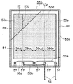
図6の面状発熱体51aの平面図に示すように、樹脂と導電性カーボンを混練してフィルム状にしたPTC特性を有する高分子抵抗体52の上に、銅撚り線(金属細線)からなる電極線53a、53b、53c、53d、53eを配設し、電気絶縁性基材であるホットメルト樹脂をラミネートしたPETフィルム54で高分子抵抗体52と電極線53a〜53eを両側から挟み込み、熱プレスあるいは熱ラミネートによりPETフィルム54、高分子抵抗体52、電極線53a〜53eを熱圧着して抵抗体シート55aを形成している。この抵抗体シート55aの電極線延伸方向の片側には高分子抵抗体52が存在せず、電極線53a〜53eとPETフィルム54のみの部分が設けられ、電極線53a〜53e端部近傍のPETフィルム54を切り欠き、電極線53a〜53eの端部を露出させ、給電用引き回しリード線56a、56bと半田付け、スポット溶接あるいはスリーブ端子によるカシメ等により電気的、物理的に接続して接続部57を構成している。電極線53a〜53e同士は隣り合う電極線が異極となるように電極線53a、53c、53eを一方の極、電極線53b、53dを他方の極とし、電極線53a、53c、53eが給電用引き回しリード線56aにより繋がれており、電極線53b、53dが給電用引き回しリード線56bによって繋がれている。58は電源電線である。さらに、抵抗体シート55aの片面にはアルミ均熱板60が両面テープで貼り付けられている。
As shown in the plan view of the
電極線53a、53bの電極間距離(電極間長さ)59ab及び、電極線53d、53eの電極間距離59deはXであり、電極線53b、53cの電極間距離59bc及び53c、53dの電極間距離59cdはYとしており、X<Yとしてある。
The inter-electrode distance (inter-electrode length) 59ab of the
高分子抵抗体52はPTC特性を有しており、温度上昇に伴い抵抗値が増大する性質を持っており、特に高分子抵抗体52の抵抗値は温度の2回微分に対し0℃〜80℃の領域において常に正で有る材料をもちいている。
The
なお、高分子抵抗体52は単なるフィルムだけでなく、補強のために不織布などの補強材を貼付したり高分子抵抗体52のフィルムの中に不織布などの補強材を埋設した形態、あるいは不織布などの補強材に樹脂と導電性カーボンを混練した材料を含浸させた形態でもよい。
The
また、電極線53a〜53fとして銅撚り線と用いる場合に代えて、高分子抵抗体52との密着性をより強固にするために、高分子抵抗体52と同一材料または近似した組成材料を被覆した被覆線でもよく、面状発熱体51が可撓性をそれほど必要としない箇所に使用されるならば、銅単線や銅平線でもよい。電極線の素材としても、銅だけでなく他の金属線を用いてもよい。
Further, instead of using a copper stranded wire as the
また、本実施の形態3においては、同一のPETフィルム4を使用しているが、必要に応じて互いに厚みの異なるPETフィルムを用いてもよく、フィルムの材質も機能が維持できるならば違っていてもよい。 In the third embodiment, the same PET film 4 is used. However, if necessary, PET films having different thicknesses may be used, and the material of the film is different as long as the function can be maintained. May be.
また、アルミ均熱板60の素材はアルミでなく、より均熱性を高めるために銅としてもよく、面状発熱体51が均熱性をそれほど必要としないのであれば、より簡便に鉄としたり省略したりしてもよい。
Further, the material of the
図7は面状発熱体51aが実装される電池モジュール内の電池セル接続図であり、被加熱物であるバッテリー62は複数の電池セルを直列接続した電池モジュール61を積層して構成し、そのバッテリー62の1面に対向して面状発熱体51aが、支持体63によりアルミ均熱板60を介して支持され、バッテリー62との間に隙間を設けて固定されている。面状発熱体51aは制御手段64によりバッテリー温度が予め設定された温度条件以下となった場合や使用者の意思によりON−OFFをすることが可能となっている。
FIG. 7 is a battery cell connection diagram in a battery module on which the
以上のように構成された面状発熱体において、以下その動作、作用を説明する。 In the planar heating element configured as described above, the operation and action will be described below.
高分子抵抗体52はPTC特性を有しているので、面状発熱体51aに通電を行い、ある程度の時間がたつと温度上昇に伴い抵抗値が増大した結果出力W数が落ち、発熱と放熱が釣り合った所で安定温度に至る。そのため、PTC特性で温度制御を行う面状発熱体51a固有の性質として面状発熱体51aの面内で放熱量が異なることによる温度分布ができる。本発明の実施の形態3では面状発熱体51aは端面で支持体63に支持されており、特に面状発熱体51aの端面は放熱しやすく温度上昇がしにくくなっている。しかしながら、最端部の電極間距離59ab、59deは中央部の電極間距離59bc、59cdよりも狭くなっているため、電極線53a、53b及び電極線53d、53eで形成される発熱部は、電極線53b、53c及び電極線53c、53dで形成される発熱部よりも発熱量が大きく、温度上昇しやすい構成となっている。そのため、面状発熱体51aの温度分布を少なくすることができ、放熱しやすい部位をより加熱するため結果としてバッテリー62へ熱伝導しやすくすることができる。面状発熱体51aの温度分布が小さくなることにより、被加熱体であるバッテリー62の温度分布も小さくでき、電池モジュール61同士の出力のムラを小さくできる。なお、「温度分布」とは、発熱体(すなわち面状発熱体)および被加熱体(すなわちバッテリー)ともに吸熱と放熱がなされてできた結果の温度の分布のことである。
Since the
次に面状発熱体51aの出力について説明する。面状発熱体51aは温度上昇しにくい部位である電極線53a、53b及び電極線53d、53eで形成される発熱部で高い出力を出している。そのため、当然、過度の温度上昇に至る危険性は極めて低く、高い信頼性を必要とし、過度の温度上昇を嫌うバッテリー62に対し非常に有用である。加えて、同一抵抗体材料及び同一面積の面状発熱体において電極間隔を均等にした面状発熱体と比較すると、面状発熱体51aは突入総出力電力を大きくすることができ、温度上昇の立ち上がり速度をより俊敏にすることが可能であり、かつ面状発熱体の省スペース化を行うことが可能である。この事は突入時には面状発熱体51aには温度分布が無いとして、並列抵抗の計算を比較すれば容易に示すことが出来るがここでは割愛する。面状発熱体51aはバッテリー62の電気容量が低下する−10℃以下の極低温環境下で使用され、電圧や放熱状態、PTC特性にもよるが面状発熱体51aの安定温度は0℃〜80℃となる。この面状発熱体51aが安定温度に達した際の出力は同一抵抗体材料及び同一面積の面状発熱体において、電極間隔を均等にした面状発熱体よりも大きくすることができ、バッテリー62の温度上昇の立ち上がり速度をより俊敏にすることが可能であり、かつ面状発熱体の省スペース化を行うことが可能である。この事は高分子抵抗体52の抵抗値が温度の2回微分に対し0℃〜80℃の領域において常に正で有ることを条件とし、発熱部ごとの平均温度を規定して並列抵抗の計算を比較すれば容易に示すことが出来るがここでは割愛する。
Next, the output of the
本発明の実施の形態3によれば、抵抗体材料を調整すること無く、電極間隔の調整のみで面状発熱体の出力分布をつけることができ、上述の作用、効果を得られるため、温度ムラが少なく、立ち上がり時及び温度安定時の総出力が大きい面状発熱体を非常に簡便に提供することができる。なお、「出力分布」とは、発熱しようとする出力の分布であり、放熱を考慮しない。 According to the third embodiment of the present invention, the output distribution of the planar heating element can be obtained only by adjusting the electrode interval without adjusting the resistor material, and the above-described functions and effects can be obtained. A planar heating element with little unevenness and a large total output at the time of start-up and temperature stabilization can be provided very simply. Note that the “output distribution” is a distribution of output that tends to generate heat, and does not consider heat dissipation.
(実施の形態4)
本発明の実施の形態4の面状発熱体を図8および図9を参照して説明する。図8は面状発熱体の平面図、図9は面状発熱体が実装される電池モジュール内の電池セル接続図である。(Embodiment 4)
A planar heating element according to Embodiment 4 of the present invention will be described with reference to FIGS. FIG. 8 is a plan view of the planar heating element, and FIG. 9 is a connection diagram of battery cells in the battery module on which the planar heating element is mounted.
図8において、面状発熱体51bは、電極線、抵抗体、PETフィルムからなる抵抗体シートおよび接続部などの基本的構成は上述の実施の形態3と同一であるが、本実施の形態4では、電極間距離59abのみ他の電極間距離59bc、59cd、59deよりも小さくなっている。また、図示していないが、面状発熱体51cは面状発熱体51bを電極線3eに対し線対称とした形状になっており、2枚の面状発熱体51b、51cはいずれも、電極53aと53bの間の電極間距離59abが他の電極間距離と比べて小さく設定されている。図9においてバッテリー62に支持体63によって面状発熱体51b、51cが取り付けられている。ここで、電極間距離の小さい電極53a側がそれぞれ支持体63の近傍になるように取り付けられている。
In FIG. 8, the
以上のような構成とすることによって、前述した実施の形態3と同一の作用、効果を電極線53a,53b間で有するとともにバッテリー62の電池モジュール61が多く積層され、1枚の面状発熱体では覆いきれない場合においても本発明の面状発熱体51b、51cを2枚使用することによって、それぞれの面状発熱体51b、51cの片側の端部とそれぞれの支持体63が一致するような放熱しやすい部位(すなわち、被加熱体の端部近傍に相当する部位)の発熱量を増やすことができる。逆側の面状発熱体51b、51cの端部は被加熱体の端部とならないため、電極間長さを小さくする必要はない。
With the configuration as described above, the same operation and effect as those of the third embodiment described above are provided between the
また、電池モジュール61がさらに多く積層された場合において3枚以上の面状発熱体を用い、両端に本発明の面状発熱体51b、51cを端面に配置することが有用であることは言うまでも無い。
In addition, when
また、実施の形態3および4の面状発熱体において、上述の実施の形態1および2の構成を採用しても良い。 Further, in the planar heating elements of the third and fourth embodiments, the configurations of the first and second embodiments described above may be employed.
なお、上記様々な実施形態のうちの任意の実施形態を適宜組み合わせることにより、それぞれの有する効果を奏するようにすることができる。 It is to be noted that, by appropriately combining arbitrary embodiments of the various embodiments described above, the effects possessed by them can be produced.
本発明は、添付図面を参照しながら好ましい実施の形態に関連して充分に記載されているが、この技術の熟練した人々にとっては種々の変形や修正は明白である。そのような変形や修正は、添付した請求の範囲による本発明の範囲から外れない限りにおいて、その中に含まれると理解されるべきである。 While the invention has been fully described in connection with preferred embodiments with reference to the accompanying drawings, various changes and modifications will be apparent to those skilled in the art. Such changes and modifications are to be understood as being included therein, so long as they do not depart from the scope of the present invention according to the appended claims.
2010年11月8日に出願された日本国特許出願No.2010−249283号の明細書、図面、及び特許請求の範囲の開示内容、および2011年4月20日に出願された日本国特許出願No.2011−093747号の明細書、図面、及び特許請求の範囲の開示内容は、全体として参照されて本明細書の中に取り入れられるものである。 Japanese patent application No. 10 filed on Nov. 8, 2010. 2010-249283, the disclosure of the specification, drawings, and claims, and Japanese Patent Application No. 2010 filed on Apr. 20, 2011. The disclosure of the specification, drawings, and claims of 2011-093747 is hereby incorporated by reference in its entirety.
本発明にかかる面状発熱体は、電極部においても薄肉・平滑で搭載性が高く、信頼性・安全性が高く、低コストで製造可能な暖房用発熱体として床暖房器具や露・霜除去用として自動車のドアミラーや洗面台のミラー、車載用バッテリーヒータ、その他の部位の暖房に供することができる。 The planar heating element according to the present invention is thin, smooth and highly mountable in the electrode part, has high reliability and safety, and can be manufactured at low cost. It can be used for heating a door mirror of a car, a mirror of a wash basin, an in-vehicle battery heater, and other parts.
また、本発明にかかる面状発熱体は、面状発熱体の発熱分布を電極間距離の調整のみで調整でき被加熱体の温度分布を均一にでき、面状発熱体の単位面積当たりの発熱量の向上が図れ、過度の温度上昇の心配の無い安全で信頼性の高い面状発熱体が提供出来るため、寒冷地向けのハイブリット車や電気自動車等のバッテリー加熱は勿論のこと、その他の加熱用ヒータとして幅広く適用することができる。 In addition, the planar heating element according to the present invention can adjust the heating distribution of the planar heating element only by adjusting the distance between the electrodes, can make the temperature distribution of the heated body uniform, and generates heat per unit area of the planar heating element. The amount of heat can be improved, and a safe and reliable planar heating element without worrying about excessive temperature rise can be provided. Therefore, not only battery heating for hybrid vehicles and electric vehicles for cold districts, but also other heating It can be widely applied as a heater.
Claims (9)
電気絶縁性基材上に配置されたシート状の高分子抵抗体と、
導電性の被覆層により被覆された金属細線を有し、高分子抵抗体のシート状の表面に沿って配置されて高分子抵抗体に給電する少なくとも一対の電極と、
電極および高分子抵抗体を間に挟んで電気絶縁性基材と対向して配置され、電極および高分子抵抗体を覆うようにホットメルトを介して電気絶縁性基材と接着されたシート状の電気絶縁性被覆材と、を備え、
電極における被覆層の断面形状は、電気絶縁性基材のシート状の表面沿いの方向に長軸を持つ略楕円形である、面状発熱体。A sheet-like electrically insulating substrate;
A sheet-like polymer resistor disposed on an electrically insulating substrate;
A thin metal wire coated with a conductive coating layer, disposed along the sheet-like surface of the polymer resistor, and at least a pair of electrodes for feeding the polymer resistor;
A sheet-like material that is disposed opposite to the electrically insulating substrate with the electrode and polymer resistor interposed therebetween, and is bonded to the electrically insulating substrate through hot melt so as to cover the electrode and the polymer resistor. An electrically insulating covering material,
The cross-sectional shape of the coating layer in an electrode is a planar heating element which is a substantially ellipse which has a long axis in the direction along the sheet-like surface of an electrically insulating base material.
少なくとも1つの対の電極間長さが他の対の電極間長さと相違するように、シート状の高分子抵抗体上にそれぞれの電極が配置されている、請求項1から4のいずれか1つに記載の面状発熱体。As at least a pair of electrodes, adjacent electrodes have different polarities, and have at least three or more electrodes arranged substantially in parallel,
5. The electrode according to claim 1, wherein each electrode is disposed on the sheet-like polymer resistor so that the length between at least one pair of electrodes is different from the length between other pairs of electrodes. The sheet heating element described in 1.
Applications Claiming Priority (5)
| Application Number | Priority Date | Filing Date | Title |
|---|---|---|---|
| JP2010249283 | 2010-11-08 | ||
| JP2010249283 | 2010-11-08 | ||
| JP2011093747 | 2011-04-20 | ||
| JP2011093747 | 2011-04-20 | ||
| PCT/JP2011/006235 WO2012063473A1 (en) | 2010-11-08 | 2011-11-08 | Planar heating element and production method for same |
Publications (1)
| Publication Number | Publication Date |
|---|---|
| JPWO2012063473A1 true JPWO2012063473A1 (en) | 2014-05-12 |
Family
ID=46050638
Family Applications (1)
| Application Number | Title | Priority Date | Filing Date |
|---|---|---|---|
| JP2012542811A Pending JPWO2012063473A1 (en) | 2010-11-08 | 2011-11-08 | Planar heating element and manufacturing method thereof |
Country Status (5)
| Country | Link |
|---|---|
| US (1) | US9204496B2 (en) |
| EP (1) | EP2640161B1 (en) |
| JP (1) | JPWO2012063473A1 (en) |
| CN (1) | CN103202093B (en) |
| WO (1) | WO2012063473A1 (en) |
Families Citing this family (21)
| Publication number | Priority date | Publication date | Assignee | Title |
|---|---|---|---|---|
| JPWO2014010252A1 (en) * | 2012-07-13 | 2016-06-20 | パナソニックIpマネジメント株式会社 | Battery heating device |
| JP6074619B2 (en) * | 2013-02-20 | 2017-02-08 | パナソニックIpマネジメント株式会社 | Manufacturing method of planar heating element |
| CN103340743B (en) * | 2013-07-24 | 2015-04-08 | 胡木明 | Warm moxibustion foot reflexology cup |
| FR3015172B1 (en) * | 2013-12-12 | 2019-05-10 | Total Sa | ELECTRICAL HEATING DEVICE |
| KR20150094488A (en) * | 2014-02-07 | 2015-08-19 | 코넷시스 주식회사 | Thermal Image Target |
| CN106133995B (en) | 2014-04-10 | 2019-11-15 | 伊利诺斯工具制品有限公司 | heater for electric vehicle battery |
| CN107431237B (en) * | 2014-12-01 | 2020-04-21 | 美国电化学动力公司 | All-solid-state lithium battery |
| CN108184507A (en) * | 2015-04-21 | 2018-06-22 | 吴昊 | A kind of agricultural cultivation greenhouse |
| KR102487620B1 (en) * | 2015-09-15 | 2023-01-12 | 엘지이노텍 주식회사 | Thin film type heater for camera module and camera module having the same |
| DE102016105774A1 (en) * | 2016-03-30 | 2017-10-05 | Jenoptik Advanced Systems Gmbh | Heatable surface element and method for producing the same |
| JP6174220B1 (en) * | 2016-10-07 | 2017-08-02 | イシイ株式会社 | Planar heating element, planar heating device, planar heating element electrode, and manufacturing method of planar heating element |
| KR101762094B1 (en) * | 2017-04-04 | 2017-07-26 | 김이태 | Power connector only for heat film |
| GB2566550B (en) | 2017-09-19 | 2022-07-13 | Gkn Aerospace Services Ltd | Electrothermal heater mat and method of manufacture thereof |
| US11234297B2 (en) * | 2018-02-26 | 2022-01-25 | Charmgraphene Co., Ltd. | Plate heater |
| JP2019175671A (en) * | 2018-03-28 | 2019-10-10 | セーレン株式会社 | Sheet heating element |
| KR102086426B1 (en) * | 2018-03-28 | 2020-03-09 | 주식회사 유니크 | Hot wire device having pressing type electrode |
| WO2020022520A1 (en) * | 2018-07-27 | 2020-01-30 | 株式会社ニフコ | Planar heat generating body and vehicle windshield device |
| WO2022180162A1 (en) * | 2021-02-25 | 2022-09-01 | Oerlikon Metco Ag, Wohlen | Method of production of a heating component by thermal spray and heating component |
| WO2024122046A1 (en) * | 2022-12-09 | 2024-06-13 | タチバナテクノス株式会社 | Planar heater |
| US20240377166A1 (en) * | 2023-05-11 | 2024-11-14 | Christopher M. Thompson | Thermal shooting targets and systems |
| WO2025094994A1 (en) * | 2023-11-02 | 2025-05-08 | 株式会社Ihi | Welding device |
Family Cites Families (15)
| Publication number | Priority date | Publication date | Assignee | Title |
|---|---|---|---|---|
| JPH01197160A (en) | 1988-02-01 | 1989-08-08 | Mazda Motor Corp | Brake controller of vehicle |
| JPH0384888A (en) | 1989-08-25 | 1991-04-10 | Idemitsu Kosan Co Ltd | Manufacture of plane heating body |
| JPH0589952A (en) * | 1991-09-30 | 1993-04-09 | Dainippon Ink & Chem Inc | Method of manufacturing sheet heating element |
| JPH08111282A (en) * | 1994-10-11 | 1996-04-30 | Idemitsu Kosan Co Ltd | Multi-layer sheet heating element and method for coating exterior sheet thereof |
| JPH09190841A (en) | 1996-01-05 | 1997-07-22 | Kojundo Chem Lab Co Ltd | Battery heating device |
| CN1228238A (en) * | 1997-01-13 | 1999-09-08 | 出光兴产株式会社 | planar heating element |
| JPH10208851A (en) * | 1997-01-21 | 1998-08-07 | Idemitsu Kosan Co Ltd | Heating / warming device |
| JPH10241841A (en) * | 1997-02-26 | 1998-09-11 | Idemitsu Kosan Co Ltd | Heating / warming device using heat storage material |
| JPH118102A (en) * | 1997-04-23 | 1999-01-12 | Matsushita Electric Works Ltd | Heating element and hair set device |
| JPH1197160A (en) | 1997-09-22 | 1999-04-09 | Showa Electric Wire & Cable Co Ltd | Planar heating element |
| JP2001110552A (en) * | 1999-10-08 | 2001-04-20 | Shuho Kk | Foldable sheet heating element |
| US8519305B2 (en) * | 2008-02-18 | 2013-08-27 | Panasonic Corporation | Polymer heating element |
| JP2010020989A (en) * | 2008-07-10 | 2010-01-28 | Panasonic Corp | Polymer heating element |
| JP5604053B2 (en) | 2009-04-20 | 2014-10-08 | 株式会社ブリヂストン | Pipe fitting |
| JP2011093747A (en) | 2009-10-30 | 2011-05-12 | Quartz Lead Co Ltd | Quartz crucible and method for manufacturing the same |
-
2011
- 2011-11-08 JP JP2012542811A patent/JPWO2012063473A1/en active Pending
- 2011-11-08 US US13/883,940 patent/US9204496B2/en active Active
- 2011-11-08 CN CN201180053883.7A patent/CN103202093B/en active Active
- 2011-11-08 EP EP11840698.2A patent/EP2640161B1/en active Active
- 2011-11-08 WO PCT/JP2011/006235 patent/WO2012063473A1/en not_active Ceased
Also Published As
| Publication number | Publication date |
|---|---|
| US9204496B2 (en) | 2015-12-01 |
| CN103202093A (en) | 2013-07-10 |
| EP2640161B1 (en) | 2017-11-08 |
| EP2640161A4 (en) | 2015-08-26 |
| CN103202093B (en) | 2016-01-20 |
| EP2640161A1 (en) | 2013-09-18 |
| US20130220994A1 (en) | 2013-08-29 |
| WO2012063473A1 (en) | 2012-05-18 |
Similar Documents
| Publication | Publication Date | Title |
|---|---|---|
| WO2012063473A1 (en) | Planar heating element and production method for same | |
| US9748618B2 (en) | Battery assembly having a heat-dissipating and heat-emitting functions | |
| US20150188204A1 (en) | Battery heating device | |
| EP2451004A1 (en) | Heating device and battery unit provided therewith | |
| US9252402B2 (en) | Battery system | |
| US20200189428A1 (en) | Sheet-type heating element and armrest of vehicle door including the same | |
| JP2008300050A (en) | Polymer heating element | |
| CN218525640U (en) | Heating membrane group for heating power battery | |
| WO2012114739A1 (en) | Planar heating element | |
| JP2010160954A (en) | Surface heater | |
| JPH0471182A (en) | Car warming device | |
| JP2005011651A (en) | Planar heating element, heating device using the planar heating element, and method for manufacturing the planar heating element | |
| CN118647098A (en) | A heating film assembly, battery cell module, battery pack and design method | |
| JP5061769B2 (en) | Planar heating element | |
| JP2578871Y2 (en) | Planar heating element | |
| JP4633587B2 (en) | Mirror for vehicle with heater and method for manufacturing the same | |
| JPH10208851A (en) | Heating / warming device | |
| JP2002015844A (en) | Electric heating unit and electric floor heating panel using the same | |
| JP5194726B2 (en) | Planar heating element | |
| CN223928472U (en) | Irradiation-resistant thin film heater | |
| CN106131980A (en) | A kind of electricity heat-producing machine | |
| CN223231343U (en) | Planar PTC heating element and battery module heating system | |
| JP2011003329A (en) | Polymer heating element | |
| JP2014164983A (en) | Battery heating device | |
| CN110858677B (en) | Battery module with heater |
Legal Events
| Date | Code | Title | Description |
|---|---|---|---|
| A711 | Notification of change in applicant |
Free format text: JAPANESE INTERMEDIATE CODE: A711 Effective date: 20141006 |
|
| RD03 | Notification of appointment of power of attorney |
Free format text: JAPANESE INTERMEDIATE CODE: A7423 Effective date: 20141014 |