KR0152995B1 - Catheter with backflow restriction - Google Patents
Catheter with backflow restrictionInfo
- Publication number
- KR0152995B1 KR0152995B1 KR1019900007045A KR900007045A KR0152995B1 KR 0152995 B1 KR0152995 B1 KR 0152995B1 KR 1019900007045 A KR1019900007045 A KR 1019900007045A KR 900007045 A KR900007045 A KR 900007045A KR 0152995 B1 KR0152995 B1 KR 0152995B1
- Authority
- KR
- South Korea
- Prior art keywords
- catheter
- needle
- tube
- catheter tube
- cannula
- Prior art date
- Legal status (The legal status is an assumption and is not a legal conclusion. Google has not performed a legal analysis and makes no representation as to the accuracy of the status listed.)
- Expired - Fee Related
Links
Images


Classifications
-
- A—HUMAN NECESSITIES
- A61—MEDICAL OR VETERINARY SCIENCE; HYGIENE
- A61M—DEVICES FOR INTRODUCING MEDIA INTO, OR ONTO, THE BODY; DEVICES FOR TRANSDUCING BODY MEDIA OR FOR TAKING MEDIA FROM THE BODY; DEVICES FOR PRODUCING OR ENDING SLEEP OR STUPOR
- A61M25/00—Catheters; Hollow probes
- A61M25/0009—Making of catheters or other medical or surgical tubes
-
- A—HUMAN NECESSITIES
- A61—MEDICAL OR VETERINARY SCIENCE; HYGIENE
- A61M—DEVICES FOR INTRODUCING MEDIA INTO, OR ONTO, THE BODY; DEVICES FOR TRANSDUCING BODY MEDIA OR FOR TAKING MEDIA FROM THE BODY; DEVICES FOR PRODUCING OR ENDING SLEEP OR STUPOR
- A61M25/00—Catheters; Hollow probes
-
- A—HUMAN NECESSITIES
- A61—MEDICAL OR VETERINARY SCIENCE; HYGIENE
- A61M—DEVICES FOR INTRODUCING MEDIA INTO, OR ONTO, THE BODY; DEVICES FOR TRANSDUCING BODY MEDIA OR FOR TAKING MEDIA FROM THE BODY; DEVICES FOR PRODUCING OR ENDING SLEEP OR STUPOR
- A61M25/00—Catheters; Hollow probes
- A61M25/01—Introducing, guiding, advancing, emplacing or holding catheters
- A61M25/06—Body-piercing guide needles or the like
- A61M25/0606—"Over-the-needle" catheter assemblies, e.g. I.V. catheters
Landscapes
- Health & Medical Sciences (AREA)
- Life Sciences & Earth Sciences (AREA)
- Biophysics (AREA)
- Pulmonology (AREA)
- Engineering & Computer Science (AREA)
- Anesthesiology (AREA)
- Biomedical Technology (AREA)
- Heart & Thoracic Surgery (AREA)
- Hematology (AREA)
- Animal Behavior & Ethology (AREA)
- General Health & Medical Sciences (AREA)
- Public Health (AREA)
- Veterinary Medicine (AREA)
- Media Introduction/Drainage Providing Device (AREA)
- Infusion, Injection, And Reservoir Apparatuses (AREA)
- Pharmaceuticals Containing Other Organic And Inorganic Compounds (AREA)
Abstract
내용없음No content
Description
제1도는 바늘 허브내의 플래시 챔버로의 혈액이 흐르는 카테테르 및 바늘 조립체를 도시한 도시도.1 illustrates a catheter and needle assembly through which blood flows to a flash chamber in a needle hub.
제2도는 바늘 보호대의 노우즈에서 혈액 역류 및 혈액 풀링(pooling)을 도시한 도시도.2 is a diagram showing blood backflow and blood pooling at the nose of a needle guard.
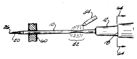
제3도는 본 발명의 원리에 따라 형성된 수축부를 갖는 카테테르를 도시한 도시도.3 shows a catheter with shrinkage formed in accordance with the principles of the present invention.
제4a도내지 제4d도는 제 3도의 수축부를 성형하는데 있어서 포함된 과정을 도시한 도시도.4a through 4d illustrate the processes involved in shaping the shrinkage of FIG.
제5a도 내지 제5c도는 제4a도 내지 제4d도에 형성된 수축부의 확대도.5A to 5C are enlarged views of the contraction portion formed in FIGS. 4A to 4D.
* 도면의 주요부분에 대한 부호의 설명* Explanation of symbols for main parts of the drawings
10 : 캐뉼러 12 : 허브10: cannula 12: hub
16 : 슬리브 20 : 바늘16: sleeve 20: needle
22 : 플래시 챔버 24 : 플러그22
26 : 팁 30 : 하우징26: tip 30: housing
36 : 노우즈 50 : 수축부36: nose 50: shrinkage
본 발명은 I.V. 카테테르(intravenous catheter)에 관한 것으로서, 특히 상기 카테테르 사용시 혈액과의 부주의한 접촉을 초래하는 혈액 풀링(pooling) 및 혈액 역류의 방지에 관한 것이다.The present invention is directed to I.V. It relates to catheter (intravenous catheter), in particular to the prevention of blood pooling and blood backflow resulting in inadvertent contact with blood when using the catheter.
1989년 4월 10일 출원된 미국 특허출원 제 335,472호와 미국 특허 제 4,762,516[루터(Luther)등]에는 카테테르 바늘 사용에 의한 바늘 찔림(stick)에 의해 야기된 부주의한 위험으로부터 의료요원을 보호하도록 설계된 바늘 보호대를 갖는 I.V. 카테테르가 기술되어 있다. 이런 부주의한 바늘 찔림은 바늘이 이미 제거된 환자의 임파 관계로부터 환자의 혈액에 의해 형성된 질병의 감염으로 귀착된다. 상술의 특허 및 특허 출원에서 서술된 카테테르는 바늘이 환자의 몸에서 제거될 때 바늘 허브(hub)로부터 연장되는 바늘 보호대로 바늘 팁을 덮음으로써 부주의한 바늘 찔림을 방지한다.US Patent Application No. 335,472 and US Patent No. 4,762,516 (Luther et al.), Filed April 10, 1989, protect medical personnel from inadvertent risks caused by needle sticks caused by catheter needle use. IV with needle guard designed to Catheter is described. This careless needle puncture results from infection of the disease formed by the patient's blood from the lymphatic relationship of the patient with the needle already removed. The catheter described in the above patents and patent applications prevents inadvertent needle sticking by covering the needle tip with a needle guard extending from the needle hub when the needle is removed from the patient's body.
불의의 바늘 찔림의 위험으로부터 의료 요원을 보호하고 또한 환자 혈액의 예기치 못한 접촉으로부터 보호를 제공하는 것은 매우 바람직하다. 심지어 상술된 바늘 보호대를 구비한 하나의 카테테르의 사용에 있어서도 의료 요원이 카테테르로부터의 불필요한 혈액 누출로 인하여 환자 혈액과의 접촉될 수도 있다. 환자의 임파 관계내로 바늘이 삽입될 동안, 카테테르를 관리하는 의료요원은 환자의 동맥 또는 정맥 내에서 바늘 팁을 적절히 배치시킬 것이다. 바늘 팁이 적절히 배치되었을 때, 바늘의 중심 단부에서의 플래시 챔버(flash chamber)내와 중공 바늘을 통하여 혈액의 미세한 흐름 또는 플래시가 발생된다. 의료 요원은 플래시 챔버내의 혈액의 이러한 형성을 적합한 바늘 위치의 표시로 인식할 것이다. 따라서 의료 요원은 카테테르 캐뉼러를 혈액 용기의 정위치에 위치시킨 채로 카테테르를 임파 관계내로 진행시키고 환자로부터 바늘을 제거한다.It is highly desirable to protect medical personnel from the risk of accidental needle puncture and to provide protection from unexpected contact of patient blood. Even in the use of a single catheter with the needle guard described above, medical personnel may be contacted with patient blood due to unnecessary blood leakage from the catheter. While the needle is inserted into the patient's lymphatic relationship, the medical personnel managing the catheter will properly place the needle tip in the patient's artery or vein. When the needle tip is properly positioned, a fine flow or flash of blood is generated in the flash chamber at the central end of the needle and through the hollow needle. The medical personnel will recognize this formation of blood in the flash chamber as an indication of a suitable needle position. The medical personnel therefore advance the catheter into the lymphatic relationship with the catheter cannula in place in the blood vessel and remove the needle from the patient.
바늘 팁이 카테테르의 중앙의 말단부 위치로 이동될 때, 혈액은 정맥압 또는 동맥압하에서 중공 바늘내로 흐를 것이다. 그러나 또한 혈액은 바늘의 외벽과 카테테르 캐튤러의 내벽 사이에서 동맥 공간으로 유입된다. 카테테르 허브를 향한 이러한 공간내의 혈액 흐름이 여기서는 역류로 기술된다. 일반적으로 혈액 역류는 바늘이 카테테르로부터 제거되면 카테테르 허브가 일반적으로 신속하게 튜브 세트에 접속되기 때문에 중요하지 않다. 그러나, 바늘 보호대를 갖는 상술의 카테테르에서, 바늘 보호대의 원심 노우즈(distal nose)는 바늘의 완전한 제거 이전에 카테테르 허브를 점유하고 있다. 바늘 보호대가 바늘 팁을 향하여 바늘의 전장을 따라 연장되기 때문에, 그 연장부는 카테테르를 환자의 정맥 또는 동맥내로 관통 통과시키는 동시에 카테테르 허브를 운반할 것이다. 이러한 운동이 종료되면 상기 호보대가 그 전체 연장부에 도달되었을 때 보호대의 노우즈로부터 카테테르 허브를 배출할 것이다. 따라서, 만일 카테테르내로의 혈액 역류가 보호대 노우즈로부터 카테테르 허브의 배출 이전에 발생되면, 바늘 보호대는 카테테르 허브를 해제시키기 전에 환자의 혈액을 오염시킬 것이다. 바늘 보호대 노우즈상에서 의료 요원의 혈액 접촉이 방지되도록 이런 오염을 방지하는 것이 바람직하다.When the needle tip is moved to the central distal position of the catheter, blood will flow into the hollow needle under venous or arterial pressure. But blood also enters the arterial space between the outer wall of the needle and the inner wall of the catheter catheter. Blood flow in this space towards the catheter hub is described herein as countercurrent. In general, blood reflux is not important because the catheter hub is generally quickly connected to the tube set once the needle is removed from the catheter. However, in the above-described catheter with needle guards, the distal nose of the needle guards occupies the catheter hub prior to complete removal of the needle. Since the needle guard extends along the full length of the needle towards the needle tip, the extension will carry the catheter hub while simultaneously passing the catheter into the vein or artery of the patient. At the end of this exercise the catheter hub will be ejected from the guard's nose when the guard has reached its full extension. Thus, if blood backflow into the catheter occurs prior to the discharge of the catheter hub from the guard nose, the needle guard will contaminate the patient's blood before releasing the catheter hub. It is desirable to prevent such contamination so that blood contact of medical personnel on the needle guard nose is prevented.
본 발명의 원리에 따르면, 삽입 바늘과 카테테르 캐뉼러 사이의 혈액 역류를 방지하는 카테테르가 제공된다. 카테테르 허브 및 캐뉼러는 종래의 방법으로 형성되어 바늘의 맨드릴과 유사한 게이지 맨드릴 또는 삽입 바늘상에 장착된다. 상기 캐뉼러는 카테테르 근처에서 적어도 캐뉼러 재료의 연화 온도와 동일한 온도까지 가열된다. 캐뉼러가 가열되므로써, 길이 방향으로 미세하게 잡아 당겨진다. 이러한 인장성은 맨드릴 또는 바늘 주위에서 캐뉼러의 가열부를 단단하게 인장시킨다. 인장된 캐뉼러는 가열원이 제거되었을 때 잠시 유지된 후 해제된다. 캐뉼러가 해제되었을 때, 이것은 캐뉼러와 맨드릴 또는 바늘 사이에서 작은 환형 공간을 형성하도록 종방향 또는 반경 방향으로 미세하게 완화된다. 인장 변수의 최적화를 통하여, 최종 미세 공간은 수축부를 통하여 이들의 통로를 방지하도록 혈액 세포와 대응되는 크기로 측정되어 캐뉼러에 의해 형성된다. 상기 최적 치수는 카테테르와 바늘이 사용되는 동안 바늘이 카테테르로부터 제거되었을 때 수축부와 바늘 사이에서 마찰을 최소화시킨다. 따라서 상기 수축부는, 캐뉼러로부터 바늘이 후퇴하는 동안 아주 미세한 마찰력의 증가가 형성되는 반면 바늘과 캐뉼러 사이에서 혈액 역류를 실질적으로 감소시킨다.According to the principles of the present invention, a catheter is provided that prevents blood backflow between the insertion needle and the catheter cannula. The catheter hub and cannula are formed in a conventional manner and mounted on a gauge mandrel or insertion needle similar to the mandrel of a needle. The cannula is heated to a temperature near the catheter at least equal to the softening temperature of the cannula material. As the cannula is heated, it is pulled finely in the longitudinal direction. This tension tightly tensions the heating portion of the cannula around the mandrel or needle. The tensioned cannula is held for a while when the heat source is removed and then released. When the cannula is released, it is slightly relaxed in the longitudinal or radial direction to form a small annular space between the cannula and the mandrel or needle. Through optimization of the tensile parameters, the final microcavity is measured by the cannula and sized to correspond with the blood cells to prevent their passage through the constriction. This optimal dimension minimizes friction between the retracted portion and the needle when the needle is removed from the catheter while the catheter and needle are in use. The constriction thus substantially reduces blood backflow between the needle and the cannula while a slight increase in friction is formed during the needle retraction from the cannula.
제1도에는 상술의 특허 및 특허출원에서 기술된 구조로 구성된 바늘 보호대를 갖는 바늘과 카테테르가 도시되어 있다. 상기 조립체는 카테테르 허브(12)에 접속된 카테테르 캐뉼러(10)를 포함한다. 카테테르 허브(12)의 중심 단부에 루어 록(luer lock)이 형성된다. 상기 캐뉼러(12)는 미국 특허 제4,191,185호 [레미옥스(Lemieux)]에 서술된 것처럼, 허브(12)의 캐뉼러 중심 단부내로 젖혀진 금속 슬리브(16)의 압력 접합에 의해 허브(12)에 부착된다.1 shows a needle and a catheter with a needle guard constructed of the structure described in the above patents and patent applications. The assembly includes a
중공 금속 삽입 바늘(20)은 포인트가 형성된 원심 단부를 갖는다. 바늘(20)의 중심 단부는 바늘 허브 또는 하우징(30) 내부에 장착된 플래시 챔버(22)의 원심 단부 개구부에 점착성으로 부착된다. 하우징에의 플래시 챔버 장착은 도면에서는 도시되지 않으며, 하우징 내부로부터 플래시 챔버의 외부까지 종방향의 레일형 연장부를 포함한다. 플래시 챔버의 중심 단부는 1988년 7월 20일 출원된 미국 특허 출원 제221,579호에 기술된 다공성 플러그 (24)에 의해 삽입된다. 상기 다공성 플러그는 챔버가 공기로 충만되어 플러그의 구멍이 이를 통하여 혈액의 통과를 허용하기에 불충분한 크기로 될 때, 플래시 챔버로부터 공기를 배기시킨다.The hollow
제1도에 그 축소된 위치로 도시된 바늘 보호대(34)가 바늘 하우징(30) 내부로 미끄러지듯 장착된다. 바늘 보호대의 내부는 그 내부의 플래시 챔버를 수용하도록 중공으로 되어 있다. 바늘 보호대는 플래시 챔버의 장착 연장부가 통과되는 한쪽 측부를 통하여 종방향 개구 또는 슬롯을 갖는다. 바늘 보호대의 원신 단부 또는 노우즈(36)는 테이퍼 형성되어 상기 보호대가 연장되므로써 보호대를 통하여 바늘의 통과를 위한 구멍을 포함한다. 카테테르 허브(12)는 바늘 보호대 노우즈 (36)상에 장착되고, 보호대가 바늘 위로 완전히 연장되었을 때 카테테르와 허브가 배출될 때까지 보호대가 연장되므로써 노우즈상에서 이동된다.The
또한 제1도는 바늘 팁이 혈액 용기내로 적합하게 위치되었을 때 카테테르내로의 필요한 혈액의 흐름을 도시한다. 혈액은 정맥압 또는 동맥압하에서 도면부호 40a로 도시된 곳을 통하여 도면부호 40b로 도시된 플래시 챔버내로 흐른다.Figure 1 also shows the required blood flow into the catheter when the needle tip is properly positioned into the blood vessel. Blood flows under the venous or arterial pressure through the place shown at 40a into the flash chamber shown at 40b.
제2도는 바늘 팁이 혈액 용기내에 위치된 후 카테테르 조립체의 상대적인 부품 위치를 도시한다. 이때 바늘 보호대 (34)는 보호대의 푸시 오프 탭(push-off tab)(32)를 원심 방향으로 가압하므로써 의료 요원 근처로 연장된다. 이러한 운동은 바늘 팁(26)을 제2도에 도시된 위치까지 카테테르(10)의 원심 단부에 대응하도록 수축시키는데, 이것은 카테테르 원심 단부 내부에서 바늘 팁의 후딩(hooding)으로 언급된다. 바늘 팁 (26)이 후딩되었을 때, 혈액이 흘러 도면부호 42a 로 도시된 카테테르의 원심 단부를 충만시킨다. 제1도에 도시된 중공 바늘을 통한 혈액의 필요한 흐름에 따라, 혈액은 도면부호 42b로 도시된 카테테르 캐뉼러의 내부와 바늘의 외부 사이에서 작은 환형 공간을 통하여 그 내부로 유입된다. 혈액의 이러한 역류는 도면부호 42c 로 도시된 혈액 풀링이 발생되는 카테테르의 내부에 도달할 수 있다. 이러한 혈액의 풀링은 불필요하게 바늘 보호대 노우스(36)의 외부를 오염시키고, 도면부호 42d 로 도시된 바늘 보호대의 노우즈내로 유입된다. 본 발명의 목적은 바늘 보호대 주위에서 혈액의 풀링 및 역류를 방지하는 것이다.2 shows the relative component positions of the catheter assembly after the needle tip has been placed in the blood vessel. The
제3도는 카테테르 허브(12)의 근처에서 카테테르 캐뉼러내에 형성된 수축부(50)를 포함하는 본 발명의 원리에 따라 구성된 카테테르를 도시한다. 상기 수축부(50)는 바늘 (20)의 외부 직경 주위로 정확하게 일치되는 크기로 카테테르 캐뉼러의 감소된 내부 직경을 포함한다. 제3도에 도시된 것처럼, 혈액이 계속해서 바늘의 후딩 팁 주위와 카테테르 캐뉼러(10)의 원심 단부내로 유입되어 바늘과 캐뉼러 사이의 환형 공간을 통하여 역류되기 시작한다. 그러나, 혈액의 역류가 수축부(50)에 도달될 때, 캐뉼러 및 바늘의 상대적인 밀접한 접합은 카테테르 허브내로의 혈액의 추가 역류를 방지한다. 이것은 결과적으로 카테테르 허브내의 바늘 보호대의 노우즈(36) 주위에서 혈액 풀링에 의해 바늘 보호대 노우즈의 오염을 방지한다.3 shows a catheter constructed in accordance with the principles of the present invention that includes a constriction 50 formed in the catheter cannula near the
상기 수축부(50)는 제 4a도 내지 제 4d도와 제5a도 내지 제5d도에 도시된 것처럼 형성된다. 제4a도는 중공 바늘 (20)상에 장착된 허브(12)와 카테테르 캐뉼러(10)를 도시한다. 상기 수축부(50)는 카테테르의 부속품이 제4a도에 도시된 것처럼 조립될 때 적합하게 형성된다. 그러한, 수축부는 또한 바늘의 맨드릴과 거의 동일한 게이지의 맨드릴상에 카테테르 및 카테테르 허브를 장착시키므로서 형성된다. 바늘 자체의 수축부 형성은 일반적으로 본 장치의 조립 공정의 감소로 귀착된다.The contraction portion 50 is formed as shown in FIGS. 4A to 4D and 5A to 5D. 4A shows the
카테테르 캐뉼러(10)는 일반적으로 상표명 태프론(![]()
![]()
본 발명자는 카테테르 캐뉼러를 가열하도록 여러 가지 다른 기술을 사용하였다. 상기 기술중의 하나는 고온판이 수축부가 형성될 포인트(52)를 둘러싸도록 디스크 같은 고온판에서 0.635cm(1/4 inch) 직경의 중심구를 통해 캐뉼러에 삽입시키는 것이다. 상기 캐뉼러는 고온판에 접촉되지 않지만 섭씨 271도 (520。F)내지 섭씨 301 도 (575。F)의 범위, 양호하게는 섭씨 271도의 온도로 가열된 고온판으로부터의 대류 흐름에 의해 가열된다. 두 번째로, 양호한 기술은 섭씨 288(550。F)내지 섭씨 343도 (650。F)의 범위, 양호하게는 섭씨 316도(600。F)의 스트림을 제4b도의 도면부호 54로 표시한 바와 같이, 펜슬-팁 고온 공기총이나 다른 소스로부터 캐뉼러에 직접 향하게 하는 것이다. 상기 소스로부터의 공기 스트림에 의해 초래된 난류는 캐뉼러를 둘러싸는 공기를 캐뉼러 물질의 용융점으로 균일하게 가열시킬 것이다. 가열된 공기 스트림은 난류를 향상시키도록 수축 영역의 부근의 전향 장치판에 직접 향하게 된다. 카테테르의 작은 덩어리 때문에, 상기 예열은 짧은 시간의 주기만을 필요로 한다. 고온판의 경우에, 예열은 약 5 내지 8 초 정도이다. 펜슬-팁 고온 공기 소스(pencil-tip hot air source)의 경우, 예열은 단지 0.5 내지 1.5 초이고, 보다 긴 시간은 보다 큰 크기의(즉, 작은 게이지수) 카테테르를 가열시키는데 필요하다.We used several different techniques to heat the catheter cannula. One of these techniques is to insert the hot plate into the cannula through a 1/4 inch diameter center hole in a hot plate such as a disc so that the hot plate surrounds the point 52 where the shrinkage will be formed. The cannula is not in contact with the hot plate but is heated by convection flow from the hot plate heated to a temperature in the range of 271 degrees Celsius (520 ° F) to 301 degrees Celsius (575 ° F), preferably 271 degrees Celsius. . Secondly, a preferred technique is to designate a stream in the range of 288 degrees Celsius (550 degrees F) to 343 degrees Celsius (650 degrees F), preferably 316 degrees Celsius (600 degrees F), as indicated at 54 in FIG. Likewise, it is directed directly at the cannula from a pencil-tip hot air gun or other source. The turbulence caused by the air stream from the source will uniformly heat the air surrounding the cannula to the melting point of the cannula material. The heated air stream is directed directly to the deflector plate in the vicinity of the shrinkage region to enhance turbulence. Because of the small mass of catheter, the preheating requires only a short period of time. In the case of hot plates, the preheating is on the order of 5 to 8 seconds. In the case of a pencil-tip hot air source, the preheating is only 0.5 to 1.5 seconds, and longer time is required to heat the catheter of larger size (ie small gauge number).
예열 주기의 종결 상태에서, 캐뉼러(10)는 설정된 간격 만큼 인장된다. 이것은 카테테르 허브(12)를 파지하고 클램프(60)를 잡아 당김으로써 종결된다. 양호하게는 클램프(60)는 제위치에 고정되고, 카테테르 허브(12)의 견부(18)에 대해서 적합 고정된 황형 브래킷은 제 4C 도의 화살표(64)에 표시된 바와같이 허브를 잡아 당긴다. 20 게이지 테프론 카테테르를 사용하는 본 발명의 양호한 실시예에서, 캐뉼러는 가열을 위해 고온판을 사용할 때 0.53cm(0.21 inch)의 간격으로 인장된다. 인장된 간격은 0.38cm(0.15 inch)내지 0.76cm(0.30 inch)의 범위를 갖는다. 펜슬-팁 고온 공기 소스를 사용할 때, 캐뉼러는 20 게이지 카테테르를 위해 0.15cm(60/100 인치)의 간격으로 인장된다. 다른 카테테르 게이지는 0.05cm(0.02 inch)내지 0.254cm(0.1 inch)의 범위를 갖는다. 상기 인장된 간격은 캐뉼러의 가열 영역을 내부 바늘이나 맨드릴의 주변을 단단히 수축시키게 할 것이다. 캐뉼러가 인장된 후, 예정된 시간 동안 인장된 위치에 유지된다. 고온판을 사용하는 경우에, 인장된 위치는 2 내지 5초동안 유지된다. 펜슬-팁 공기 소스의 경우, 상기 위치는 0.1 내지 1초 동안 유지된다. 캐뉼러는 고온판의 구멍으로부터 제거되고 냉각된다. 펜슬-팁 고온 공기 소스의 예에서, 고온 공기의 스트림은 캐뉼러로부터 제거되고 캐뉼러는 인장된 위치에서 0.2 내지 1초 동안 유지된다. 인장된 캐뉼러는 해제되고 수초 동안 냉각된다.At the end of the preheat cycle, the
열이 캐뉼러로부터 제거되고 인장력이 없어졌을 때, 캐뉼러 물질은 작은 열 덩어리 때문에 매우 잠시동안 냉각 및 응고된다. 인장력없이 냉각되므로, 캐뉼러 물질은 길이 및 반경 방향으로 완화되어 팽창한다. 상기 물질의 완화는 바늘이나 맨드릴 주변의 캐뉼러의 단단한 결합을 경감시키고, 수축부가 형성된 바늘 및 맨드릴과 캐뉼러와의 사이에 좁은 환형 갭을 남겨둔다. 최적의 갭은 5.08 ×![]()
![]()
![]()
![]()
고온판이 수축부의 형성에 사용될 때, 수축부 형성 시간은 약 10초이다. 펜슬-팁 고온 공기 소스가 사용될 때, 수축부 형성 시간은 3.5초 이하이고 공칭적으로는 2 초 이하이다.When the hot plate is used to form the shrinkage, the shrinkage formation time is about 10 seconds. When a pencil-tip hot air source is used, the shrinkage formation time is no more than 3.5 seconds and nominally no more than 2 seconds.
캐뉼러 수축부 형성의 확대도가 제5a도 내지 제 5c 도에 도시되었다. 제5a도에는 최초 예열 단계에서의 카테테르 캐뉼러(10)와 바늘(20)이 도시되어 있고, 수축부가 형성될 영역 (52)에서 바늘과 캐뉼러 사이의 환형 공간부가 도시되어 있다. 제5b도는 가열된 캐뉼러가 인장될 때 참조부호 50´에서 바늘 (20) 주변에 팽팽하게 당겨진다. 화살표(62)는 인장력 방향을 나타낸다. 제5c도는 인장력 및 열이 제거된 후 발생되는 캐뉼러 물질의 완화를 도시한 것이다. 캐뉼러는 수축부의 내경과 바늘의 외경 사이의 작은 갭을 형성하도록 화살표(66)로 도시한 바와 같이 길이 방향과 반경 방향으로 완화된다. 적혈구의 공칭 직경이 약 7μ이고 백혈구의 공칭 직경이 약 12μ이기 때문에 0.5/1000인치(12.5μ)의 공칭 갭은 수축부를 통해 혈액의 흐름을 제지할 것이다.An enlarged view of cannula contraction formation is shown in FIGS. 5A-5C. 5a shows the
20 게이지 카테테르를 사용하는 본 발명의 실시예에서, 수축부(50)는 카테테르 허브에 인접하게 위치되고 0.3cm(1/8 inch)의 간격만큼 분리된다. 수축부는 0.635cm(1.4 inch)이다. I.V. 카테테라의 전형적인 카테테르 튜브는 1.27cm(1/2 inch) 내지 4.45cm(1![]()
![]()
실시예는 역류를 방지하는데 있어서 수축부의 효력을 결정하도록 벤치가 테스트된다. 카테테르 조립체는 20 내지 30mmHg 로 가압된 설탕 용액원으로 삽입된다. 카테테르 바늘은 상기 용액이 카테테르 허브에 나타난 시간을 결정하도록 감시하고, 제3도에 도시된 바와같이 후드된다. 용액의 역류가 허브에 나타날때까지 통과 시간은 최소한 18 게이지 카테테르에 대해 12.9 초, 20 게이지 카테테르에 대해 15 초, 22 게이지 카테테르에 대해 60초 이상의 범위를 갖는다. 테스트된 대부분의 카테테르에 나타난 역류를 위한 최대 시간은 60초 이상이다. 수축부 없는 유사한 카테테르는 역흐름 문제가 발생될때까지 1.2 내지 8.0 초의 범위를 갖는다. 이 테스트는 5 내지 10mmHg 의 공칭 인체 정맥압과 양호하게 비교되고, 또한 1 분 아래에서 카테테르 튜빙 세트에 연결하고, 바늘을 카테테르로부터 수축시키도록 요구된 시간과 양호하게 비교된다.The example is tested on the bench to determine the effect of the shrinkage in preventing backflow. The catheter assembly is inserted into a source of sugar solution pressurized to 20-30 mmHg. The catheter needle is monitored to determine the time the solution appears on the catheter hub and is hooded as shown in FIG. The passage time until the countercurrent of the solution appears in the hub ranges at least 12.9 seconds for an 18 gauge catheter, 15 seconds for a 20 gauge catheter and 60 seconds for a 22 gauge catheter. The maximum time for reflux seen on most catheters tested is at least 60 seconds. Similar catheter without shrinkage ranges from 1.2 to 8.0 seconds until backflow problems occur. This test compares well with the nominal human venous pressure of 5-10 mmHg and also with the time required to connect to the catheter tubing set in less than one minute and to retract the needle from the catheter.
측정된 다른 인자는 수축부를 갖는 캐뉼러로부터 바늘을 수축시키는데 요구되는 힘의 증가이다. 상기 힘의 증가는 일반적으로 100g 이상의 환자의 피부로부터 바늘을 제거키시는데 요구되는 힘과 비교된다. 1.27 ×![]()
![]()
Claims (13)
Applications Claiming Priority (3)
| Application Number | Priority Date | Filing Date | Title |
|---|---|---|---|
| US35327689A | 1989-05-17 | 1989-05-17 | |
| US353276 | 1989-05-17 | ||
| SG131294A SG131294G (en) | 1989-05-17 | 1994-09-10 | Catheter with backflow restriction |
Publications (2)
| Publication Number | Publication Date |
|---|---|
| KR900017622A KR900017622A (en) | 1990-12-19 |
| KR0152995B1 true KR0152995B1 (en) | 1998-10-15 |
Family
ID=26664319
Family Applications (1)
| Application Number | Title | Priority Date | Filing Date |
|---|---|---|---|
| KR1019900007045A Expired - Fee Related KR0152995B1 (en) | 1989-05-17 | 1990-05-17 | Catheter with backflow restriction |
Country Status (21)
| Country | Link |
|---|---|
| US (1) | US5126090A (en) |
| EP (1) | EP0398676B1 (en) |
| JP (1) | JP2837236B2 (en) |
| KR (1) | KR0152995B1 (en) |
| CN (1) | CN1027138C (en) |
| AR (1) | AR245003A1 (en) |
| AT (1) | ATE100341T1 (en) |
| AU (1) | AU629635B2 (en) |
| BR (1) | BR9002310A (en) |
| CA (1) | CA2016772C (en) |
| DE (1) | DE69006096T2 (en) |
| DK (1) | DK0398676T3 (en) |
| ES (1) | ES2048433T3 (en) |
| FI (1) | FI902429A7 (en) |
| GR (1) | GR1002523B (en) |
| NO (1) | NO176697C (en) |
| NZ (1) | NZ233609A (en) |
| PT (1) | PT94052B (en) |
| SG (1) | SG131294G (en) |
| ZA (1) | ZA903753B (en) |
| ZW (1) | ZW7790A1 (en) |
Families Citing this family (41)
| Publication number | Priority date | Publication date | Assignee | Title |
|---|---|---|---|---|
| US5256144A (en) * | 1989-11-02 | 1993-10-26 | Danforth Biomedical, Inc. | Low profile, high performance interventional catheters |
| US5209728B1 (en) * | 1989-11-02 | 1998-04-14 | Danforth Biomedical Inc | Low profile high performance interventional catheters |
| US5324263A (en) * | 1989-11-02 | 1994-06-28 | Danforth Biomedical, Inc. | Low profile high performance interventional catheters |
| US5030205A (en) * | 1989-12-18 | 1991-07-09 | Critikon, Inc. | Catheter assemblies for prevention of blood leakage |
| DE69027327T2 (en) * | 1990-11-21 | 1997-01-23 | Danforth Biomedical Inc | Sealing for catheter for surgical intervention with high performance and small size |
| US5215528C1 (en) * | 1992-02-07 | 2001-09-11 | Becton Dickinson Co | Catheter introducer assembly including needle tip shield |
| US5368801A (en) * | 1993-01-05 | 1994-11-29 | Vlv Associates | Method of mounting a septum in a connector |
| CA2135706C (en) * | 1993-11-15 | 1999-06-15 | Walter E. Cover | Retractable-needle cannula insertion set with refinements to better control leakage, retraction speed, and reuse |
| MY120112A (en) * | 1996-04-02 | 2005-09-30 | Meguro Chemical Industry Co Ltd | Sealing tape and method and apparatus for its production, and method of repairs with it |
| CA2583144C (en) * | 1996-11-15 | 2009-03-10 | Bristol Myers Squibb Company | Devices and methods for applying a mixture of two or more liquid components to form a biomaterial |
| DE20103363U1 (en) | 2001-02-26 | 2001-05-17 | Braun Melsungen Ag | Protection device for an injection needle |
| US7125397B2 (en) * | 1997-08-20 | 2006-10-24 | B. Braun Melsungen Ag | Protective device for an injection needle |
| US6117108A (en) | 1997-08-20 | 2000-09-12 | Braun Melsungen Ag | Spring clip safety IV catheter |
| US6616630B1 (en) * | 1997-08-20 | 2003-09-09 | B. Braun Melsungen A.G. | Spring clip safety IV catheter |
| US8211070B2 (en) * | 1997-08-20 | 2012-07-03 | B. Braun Melsungen Ag | Spring clip safety IV catheter |
| US8382721B2 (en) | 1997-08-20 | 2013-02-26 | B. Braun Melsungen Ag | Spring clip safety IV catheter |
| EP0900546A1 (en) | 1997-09-05 | 1999-03-10 | Irene Cristina Luis Vega | Needle-catheter assembly for medical or veterinarian use |
| DE20106697U1 (en) * | 2001-04-18 | 2001-10-31 | B. Braun Melsungen Ag, 34212 Melsungen | Catheter introducer |
| JP2004211743A (en) | 2002-12-27 | 2004-07-29 | Meguro Kagaku Kogyo Kk | Sealing tape |
| US7988664B2 (en) | 2004-11-01 | 2011-08-02 | Tyco Healthcare Group Lp | Locking clip with trigger bushing |
| US7226434B2 (en) * | 2003-10-31 | 2007-06-05 | Tyco Healthcare Group Lp | Safety shield |
| US7905857B2 (en) | 2005-07-11 | 2011-03-15 | Covidien Ag | Needle assembly including obturator with safety reset |
| US7850650B2 (en) | 2005-07-11 | 2010-12-14 | Covidien Ag | Needle safety shield with reset |
| US7828773B2 (en) | 2005-07-11 | 2010-11-09 | Covidien Ag | Safety reset key and needle assembly |
| US20060276747A1 (en) | 2005-06-06 | 2006-12-07 | Sherwood Services Ag | Needle assembly with removable depth stop |
| US7731692B2 (en) | 2005-07-11 | 2010-06-08 | Covidien Ag | Device for shielding a sharp tip of a cannula and method of using the same |
| US8197545B2 (en) | 2005-10-27 | 2012-06-12 | Depuy Spine, Inc. | Nucleus augmentation delivery device and technique |
| US20070173935A1 (en) * | 2005-10-28 | 2007-07-26 | O'neil Michael J | Nucleus pulposus augmentation pretreatment technique |
| US7654735B2 (en) | 2005-11-03 | 2010-02-02 | Covidien Ag | Electronic thermometer |
| US8382718B2 (en) | 2006-07-31 | 2013-02-26 | B. Braun Melsungen Ag | Needle assembly and components thereof |
| WO2009042874A1 (en) * | 2007-09-27 | 2009-04-02 | Tyco Healthcare Group Lp | I.v. catheter assembly and needle safety device |
| US8357104B2 (en) | 2007-11-01 | 2013-01-22 | Coviden Lp | Active stylet safety shield |
| EP2075029B1 (en) | 2007-12-20 | 2010-09-29 | Tyco Healthcare Group LP | Locking cap assembly with spring-loaded collar |
| US8382751B2 (en) | 2009-09-10 | 2013-02-26 | Covidien Lp | System and method for power supply noise reduction |
| US9113949B2 (en) | 2010-10-05 | 2015-08-25 | Medtronic, Inc. | Cannula system and method for immobilizing an implanted catheter during catheter anchoring |
| US10076387B2 (en) | 2015-06-18 | 2018-09-18 | Medtronic, Inc. | Medical device implantation and positioning system |
| KR101733019B1 (en) | 2015-07-29 | 2017-05-08 | 신현호 | Sealing tape for car repair restoration |
| CN106806964B (en) * | 2015-11-30 | 2020-03-13 | 先健科技(深圳)有限公司 | Intracavity injection catheter device |
| US10028768B2 (en) * | 2016-04-20 | 2018-07-24 | Gayle MISLE | Cannula and needle assembly |
| US10569027B2 (en) * | 2016-04-20 | 2020-02-25 | Gayle MISLE | Epidural needle assembly |
| EP3697489A4 (en) * | 2017-10-20 | 2021-09-08 | Smiths Medical ASD, Inc. | CATHETER WITH THREADING FLASH CONFIRMATION |
Family Cites Families (19)
| Publication number | Priority date | Publication date | Assignee | Title |
|---|---|---|---|---|
| US3094122A (en) * | 1961-01-18 | 1963-06-18 | Theophile E Gauthier | Flexible cannula and intravenous needle combined |
| US3406685A (en) * | 1963-07-23 | 1968-10-22 | Becton Dickinson Co | Catheter needle and method for its manufacture |
| US3388703A (en) * | 1966-03-22 | 1968-06-18 | Johnson & Johnson | Intravenous cannula assembly unit |
| US3540447A (en) * | 1967-09-29 | 1970-11-17 | Becton Dickinson Co | Spinal needle |
| US3684605A (en) * | 1970-01-21 | 1972-08-15 | Univ Utah | Method of constructing a thin-walled cannula |
| US3634924A (en) * | 1970-04-20 | 1972-01-18 | American Hospital Supply Corp | Method of making multilumen balloon catheter |
| US3719737A (en) * | 1970-12-09 | 1973-03-06 | Bard Inc C R | Method of making a preformed curved epidural catheter |
| US4106506A (en) * | 1973-12-03 | 1978-08-15 | Koehn Wilbur R | Catheter |
| US3985601A (en) * | 1975-05-05 | 1976-10-12 | Quantum, Inc. | Method for producing a balloon type catheter having a smooth continuous outer surface |
| US4212204A (en) * | 1979-04-26 | 1980-07-15 | St Amand Elmer F | Pipette and method of making same |
| US4249541A (en) * | 1979-04-26 | 1981-02-10 | David S. Pratt | Biopsy device |
| US4317445A (en) * | 1980-03-31 | 1982-03-02 | Baxter Travenol Laboratories, Inc. | Catheter insertion unit with separate flashback indication for the cannula |
| US4354495A (en) * | 1980-10-30 | 1982-10-19 | Sherwood Medical Industries Inc. | Method of connecting plastic tube to a plastic part |
| US4547194A (en) * | 1984-03-16 | 1985-10-15 | Moorehead Harvey R | Hub assemblies and extensions for indwelling catheter tubes and method |
| JPS60234671A (en) * | 1984-05-09 | 1985-11-21 | テルモ株式会社 | Catheter inserter |
| US4588398A (en) * | 1984-09-12 | 1986-05-13 | Warner-Lambert Company | Catheter tip configuration |
| US4781703A (en) * | 1985-10-17 | 1988-11-01 | Menlo Care, Inc. | Catheter assembly |
| US4840622A (en) * | 1987-10-06 | 1989-06-20 | Menlo Care, Inc. | Kink resistant catheter |
| US5030205A (en) * | 1989-12-18 | 1991-07-09 | Critikon, Inc. | Catheter assemblies for prevention of blood leakage |
-
1990
- 1990-05-14 NZ NZ233609A patent/NZ233609A/en unknown
- 1990-05-15 ZW ZW77/90A patent/ZW7790A1/en unknown
- 1990-05-15 CA CA002016772A patent/CA2016772C/en not_active Expired - Lifetime
- 1990-05-16 AU AU55084/90A patent/AU629635B2/en not_active Ceased
- 1990-05-16 FI FI902429A patent/FI902429A7/en not_active Application Discontinuation
- 1990-05-16 NO NO902188A patent/NO176697C/en unknown
- 1990-05-16 AR AR90316866A patent/AR245003A1/en active
- 1990-05-16 ZA ZA903753A patent/ZA903753B/en unknown
- 1990-05-16 GR GR900100377A patent/GR1002523B/en not_active IP Right Cessation
- 1990-05-16 JP JP2126547A patent/JP2837236B2/en not_active Expired - Fee Related
- 1990-05-16 PT PT94052A patent/PT94052B/en not_active IP Right Cessation
- 1990-05-16 ES ES90305263T patent/ES2048433T3/en not_active Expired - Lifetime
- 1990-05-16 DE DE69006096T patent/DE69006096T2/en not_active Expired - Fee Related
- 1990-05-16 EP EP90305263A patent/EP0398676B1/en not_active Expired - Lifetime
- 1990-05-16 DK DK90305263.7T patent/DK0398676T3/en active
- 1990-05-16 AT AT90305263T patent/ATE100341T1/en not_active IP Right Cessation
- 1990-05-17 BR BR909002310A patent/BR9002310A/en not_active IP Right Cessation
- 1990-05-17 CN CN90104395A patent/CN1027138C/en not_active Expired - Lifetime
- 1990-05-17 KR KR1019900007045A patent/KR0152995B1/en not_active Expired - Fee Related
- 1990-08-14 US US07/567,420 patent/US5126090A/en not_active Expired - Lifetime
-
1994
- 1994-09-10 SG SG131294A patent/SG131294G/en unknown
Also Published As
| Publication number | Publication date |
|---|---|
| JPH034875A (en) | 1991-01-10 |
| FI902429A7 (en) | 1990-11-18 |
| NO176697B (en) | 1995-02-06 |
| NO176697C (en) | 1995-05-16 |
| JP2837236B2 (en) | 1998-12-14 |
| NZ233609A (en) | 1992-10-28 |
| NO902188D0 (en) | 1990-05-16 |
| BR9002310A (en) | 1991-08-06 |
| DE69006096T2 (en) | 1994-05-19 |
| GR900100377A (en) | 1991-10-10 |
| GR1002523B (en) | 1997-01-24 |
| NO902188L (en) | 1990-11-19 |
| CN1047209A (en) | 1990-11-28 |
| DE69006096D1 (en) | 1994-03-03 |
| EP0398676B1 (en) | 1994-01-19 |
| CA2016772A1 (en) | 1990-11-17 |
| CN1027138C (en) | 1994-12-28 |
| SG131294G (en) | 1995-01-13 |
| US5126090A (en) | 1992-06-30 |
| FI902429A0 (en) | 1990-05-16 |
| CA2016772C (en) | 2000-07-18 |
| EP0398676A1 (en) | 1990-11-22 |
| ATE100341T1 (en) | 1994-02-15 |
| PT94052B (en) | 1996-09-30 |
| AU629635B2 (en) | 1992-10-08 |
| ZA903753B (en) | 1992-01-29 |
| AU5508490A (en) | 1990-11-22 |
| AR245003A1 (en) | 1993-12-30 |
| DK0398676T3 (en) | 1994-02-28 |
| ES2048433T3 (en) | 1994-03-16 |
| PT94052A (en) | 1991-01-08 |
| KR900017622A (en) | 1990-12-19 |
| ZW7790A1 (en) | 1992-02-05 |
Similar Documents
| Publication | Publication Date | Title |
|---|---|---|
| KR0152995B1 (en) | Catheter with backflow restriction | |
| AU632642B2 (en) | Catheter assemblies for resolution of blood leakage | |
| US5092845A (en) | Catheter with needle gasket | |
| US5562634A (en) | Intravenous catheter with automatically retracting needle-guide | |
| JP2788263B2 (en) | Catheter assembly | |
| JP3805432B2 (en) | Catheter needle tip protector | |
| RU2172187C2 (en) | Intravenous catheter with self-adjusting needle protecting device | |
| JP2005526526A (en) | Medical device having a safe flexible needle member | |
| BRPI0518833B1 (en) | disposal and method for making a needle safe | |
| JPH07148269A (en) | Catheter-introducing device assembly with guide wire | |
| EP0605521A1 (en) | Catheter placement units | |
| JPH09117504A (en) | Method of forming rib to cannula for needle tip protective device | |
| JP2636082B2 (en) | Puncture needle device for introducing a catheter into a blood vessel in a closed system | |
| US5156792A (en) | Method of producing catheter assemblies for prevention of blood leakage | |
| US7794445B2 (en) | Needle safety and protection device | |
| US5078687A (en) | Catheter with backflow restriction | |
| JP3093365B2 (en) | Catheter assembly with needle guard | |
| KR20210006932A (en) | Blood collection set operated by compression | |
| MXPA96002222A (en) | Ag point protector | |
| CN118647420A (en) | Medical safety needle assembly | |
| HK1002582B (en) | Catheter assemblies for prevention of blood leakage | |
| MXPA97006322A (en) | Packaging for blood blood in situ for a catheter of seguri |
Legal Events
| Date | Code | Title | Description |
|---|---|---|---|
| PA0109 | Patent application |
St.27 status event code: A-0-1-A10-A12-nap-PA0109 |
|
| R17-X000 | Change to representative recorded |
St.27 status event code: A-3-3-R10-R17-oth-X000 |
|
| P11-X000 | Amendment of application requested |
St.27 status event code: A-2-2-P10-P11-nap-X000 |
|
| P13-X000 | Application amended |
St.27 status event code: A-2-2-P10-P13-nap-X000 |
|
| PG1501 | Laying open of application |
St.27 status event code: A-1-1-Q10-Q12-nap-PG1501 |
|
| A201 | Request for examination | ||
| P11-X000 | Amendment of application requested |
St.27 status event code: A-2-2-P10-P11-nap-X000 |
|
| P13-X000 | Application amended |
St.27 status event code: A-2-2-P10-P13-nap-X000 |
|
| PA0201 | Request for examination |
St.27 status event code: A-1-2-D10-D11-exm-PA0201 |
|
| E902 | Notification of reason for refusal | ||
| PE0902 | Notice of grounds for rejection |
St.27 status event code: A-1-2-D10-D21-exm-PE0902 |
|
| P11-X000 | Amendment of application requested |
St.27 status event code: A-2-2-P10-P11-nap-X000 |
|
| P13-X000 | Application amended |
St.27 status event code: A-2-2-P10-P13-nap-X000 |
|
| E701 | Decision to grant or registration of patent right | ||
| PE0701 | Decision of registration |
St.27 status event code: A-1-2-D10-D22-exm-PE0701 |
|
| GRNT | Written decision to grant | ||
| PR0701 | Registration of establishment |
St.27 status event code: A-2-4-F10-F11-exm-PR0701 |
|
| PR1002 | Payment of registration fee |
St.27 status event code: A-2-2-U10-U11-oth-PR1002 Fee payment year number: 1 |
|
| PG1601 | Publication of registration |
St.27 status event code: A-4-4-Q10-Q13-nap-PG1601 |
|
| PR1001 | Payment of annual fee |
St.27 status event code: A-4-4-U10-U11-oth-PR1001 Fee payment year number: 4 |
|
| PR1001 | Payment of annual fee |
St.27 status event code: A-4-4-U10-U11-oth-PR1001 Fee payment year number: 5 |
|
| PR1001 | Payment of annual fee |
St.27 status event code: A-4-4-U10-U11-oth-PR1001 Fee payment year number: 6 |
|
| PR1001 | Payment of annual fee |
St.27 status event code: A-4-4-U10-U11-oth-PR1001 Fee payment year number: 7 |
|
| PR1001 | Payment of annual fee |
St.27 status event code: A-4-4-U10-U11-oth-PR1001 Fee payment year number: 8 |
|
| PR1001 | Payment of annual fee |
St.27 status event code: A-4-4-U10-U11-oth-PR1001 Fee payment year number: 9 |
|
| PR1001 | Payment of annual fee |
St.27 status event code: A-4-4-U10-U11-oth-PR1001 Fee payment year number: 10 |
|
| PR1001 | Payment of annual fee |
St.27 status event code: A-4-4-U10-U11-oth-PR1001 Fee payment year number: 11 |
|
| FPAY | Annual fee payment |
Payment date: 20090623 Year of fee payment: 12 |
|
| PR1001 | Payment of annual fee |
St.27 status event code: A-4-4-U10-U11-oth-PR1001 Fee payment year number: 12 |
|
| LAPS | Lapse due to unpaid annual fee | ||
| PC1903 | Unpaid annual fee |
St.27 status event code: A-4-4-U10-U13-oth-PC1903 Not in force date: 20100702 Payment event data comment text: Termination Category : DEFAULT_OF_REGISTRATION_FEE |
|
| PC1903 | Unpaid annual fee |
St.27 status event code: N-4-6-H10-H13-oth-PC1903 Ip right cessation event data comment text: Termination Category : DEFAULT_OF_REGISTRATION_FEE Not in force date: 20100702 |