KR100443473B1 - A device for taking out and thermoforming a workpiece from a thermoforming machine - Google Patents
A device for taking out and thermoforming a workpiece from a thermoforming machine Download PDFInfo
- Publication number
- KR100443473B1 KR100443473B1 KR1019970020607A KR19970020607A KR100443473B1 KR 100443473 B1 KR100443473 B1 KR 100443473B1 KR 1019970020607 A KR1019970020607 A KR 1019970020607A KR 19970020607 A KR19970020607 A KR 19970020607A KR 100443473 B1 KR100443473 B1 KR 100443473B1
- Authority
- KR
- South Korea
- Prior art keywords
- workpiece
- thermoforming machine
- plate
- thermoformed
- thermoforming
- Prior art date
- Legal status (The legal status is an assumption and is not a legal conclusion. Google has not performed a legal analysis and makes no representation as to the accuracy of the status listed.)
- Expired - Lifetime
Links
- 238000003856 thermoforming Methods 0.000 title claims abstract description 54
- 238000000034 method Methods 0.000 claims abstract description 24
- 238000003754 machining Methods 0.000 claims description 17
- 238000000465 moulding Methods 0.000 claims description 13
- 238000002372 labelling Methods 0.000 claims description 2
- 230000001954 sterilising effect Effects 0.000 claims description 2
- 230000001360 synchronised effect Effects 0.000 claims 1
- 230000008569 process Effects 0.000 abstract description 13
- 239000012530 fluid Substances 0.000 description 10
- 239000000463 material Substances 0.000 description 8
- 238000007493 shaping process Methods 0.000 description 5
- 238000005553 drilling Methods 0.000 description 4
- 230000009467 reduction Effects 0.000 description 4
- 239000004793 Polystyrene Substances 0.000 description 2
- 230000009471 action Effects 0.000 description 2
- 238000000605 extraction Methods 0.000 description 2
- 238000001125 extrusion Methods 0.000 description 2
- 229920002223 polystyrene Polymers 0.000 description 2
- 239000012815 thermoplastic material Substances 0.000 description 2
- 239000002699 waste material Substances 0.000 description 2
- 239000004743 Polypropylene Substances 0.000 description 1
- 238000004891 communication Methods 0.000 description 1
- 238000013016 damping Methods 0.000 description 1
- 239000000284 extract Substances 0.000 description 1
- 239000004744 fabric Substances 0.000 description 1
- 239000011521 glass Substances 0.000 description 1
- 230000013011 mating Effects 0.000 description 1
- 230000007246 mechanism Effects 0.000 description 1
- 239000008188 pellet Substances 0.000 description 1
- 229920000728 polyester Polymers 0.000 description 1
- -1 polypropylene Polymers 0.000 description 1
- 229920001155 polypropylene Polymers 0.000 description 1
- 230000002035 prolonged effect Effects 0.000 description 1
- 230000004044 response Effects 0.000 description 1
- 238000004659 sterilization and disinfection Methods 0.000 description 1
- 230000000930 thermomechanical effect Effects 0.000 description 1
Images


Classifications
-
- B—PERFORMING OPERATIONS; TRANSPORTING
- B29—WORKING OF PLASTICS; WORKING OF SUBSTANCES IN A PLASTIC STATE IN GENERAL
- B29C—SHAPING OR JOINING OF PLASTICS; SHAPING OF MATERIAL IN A PLASTIC STATE, NOT OTHERWISE PROVIDED FOR; AFTER-TREATMENT OF THE SHAPED PRODUCTS, e.g. REPAIRING
- B29C51/00—Shaping by thermoforming, i.e. shaping sheets or sheet like preforms after heating, e.g. shaping sheets in matched moulds or by deep-drawing; Apparatus therefor
- B29C51/26—Component parts, details or accessories; Auxiliary operations
- B29C51/44—Removing or ejecting moulded articles
-
- B—PERFORMING OPERATIONS; TRANSPORTING
- B29—WORKING OF PLASTICS; WORKING OF SUBSTANCES IN A PLASTIC STATE IN GENERAL
- B29C—SHAPING OR JOINING OF PLASTICS; SHAPING OF MATERIAL IN A PLASTIC STATE, NOT OTHERWISE PROVIDED FOR; AFTER-TREATMENT OF THE SHAPED PRODUCTS, e.g. REPAIRING
- B29C51/00—Shaping by thermoforming, i.e. shaping sheets or sheet like preforms after heating, e.g. shaping sheets in matched moulds or by deep-drawing; Apparatus therefor
- B29C51/26—Component parts, details or accessories; Auxiliary operations
-
- B—PERFORMING OPERATIONS; TRANSPORTING
- B29—WORKING OF PLASTICS; WORKING OF SUBSTANCES IN A PLASTIC STATE IN GENERAL
- B29C—SHAPING OR JOINING OF PLASTICS; SHAPING OF MATERIAL IN A PLASTIC STATE, NOT OTHERWISE PROVIDED FOR; AFTER-TREATMENT OF THE SHAPED PRODUCTS, e.g. REPAIRING
- B29C57/00—Shaping of tube ends, e.g. flanging, belling or closing; Apparatus therefor, e.g. collapsible mandrels
- B29C57/12—Rim rolling
-
- B—PERFORMING OPERATIONS; TRANSPORTING
- B29—WORKING OF PLASTICS; WORKING OF SUBSTANCES IN A PLASTIC STATE IN GENERAL
- B29C—SHAPING OR JOINING OF PLASTICS; SHAPING OF MATERIAL IN A PLASTIC STATE, NOT OTHERWISE PROVIDED FOR; AFTER-TREATMENT OF THE SHAPED PRODUCTS, e.g. REPAIRING
- B29C2791/00—Shaping characteristics in general
- B29C2791/004—Shaping under special conditions
- B29C2791/007—Using fluid under pressure
-
- B—PERFORMING OPERATIONS; TRANSPORTING
- B29—WORKING OF PLASTICS; WORKING OF SUBSTANCES IN A PLASTIC STATE IN GENERAL
- B29C—SHAPING OR JOINING OF PLASTICS; SHAPING OF MATERIAL IN A PLASTIC STATE, NOT OTHERWISE PROVIDED FOR; AFTER-TREATMENT OF THE SHAPED PRODUCTS, e.g. REPAIRING
- B29C33/00—Moulds or cores; Details thereof or accessories therefor
- B29C33/44—Moulds or cores; Details thereof or accessories therefor with means for, or specially constructed to facilitate, the removal of articles, e.g. of undercut articles
- B29C33/442—Moulds or cores; Details thereof or accessories therefor with means for, or specially constructed to facilitate, the removal of articles, e.g. of undercut articles with mechanical ejector or drive means therefor
-
- B—PERFORMING OPERATIONS; TRANSPORTING
- B29—WORKING OF PLASTICS; WORKING OF SUBSTANCES IN A PLASTIC STATE IN GENERAL
- B29C—SHAPING OR JOINING OF PLASTICS; SHAPING OF MATERIAL IN A PLASTIC STATE, NOT OTHERWISE PROVIDED FOR; AFTER-TREATMENT OF THE SHAPED PRODUCTS, e.g. REPAIRING
- B29C37/00—Component parts, details, accessories or auxiliary operations, not covered by group B29C33/00 or B29C35/00
- B29C37/0003—Discharging moulded articles from the mould
- B29C37/0007—Discharging moulded articles from the mould using means operable from outside the mould for moving between mould parts, e.g. robots
-
- B—PERFORMING OPERATIONS; TRANSPORTING
- B29—WORKING OF PLASTICS; WORKING OF SUBSTANCES IN A PLASTIC STATE IN GENERAL
- B29C—SHAPING OR JOINING OF PLASTICS; SHAPING OF MATERIAL IN A PLASTIC STATE, NOT OTHERWISE PROVIDED FOR; AFTER-TREATMENT OF THE SHAPED PRODUCTS, e.g. REPAIRING
- B29C51/00—Shaping by thermoforming, i.e. shaping sheets or sheet like preforms after heating, e.g. shaping sheets in matched moulds or by deep-drawing; Apparatus therefor
- B29C51/04—Combined thermoforming and prestretching, e.g. biaxial stretching
-
- B—PERFORMING OPERATIONS; TRANSPORTING
- B29—WORKING OF PLASTICS; WORKING OF SUBSTANCES IN A PLASTIC STATE IN GENERAL
- B29L—INDEXING SCHEME ASSOCIATED WITH SUBCLASS B29C, RELATING TO PARTICULAR ARTICLES
- B29L2031/00—Other particular articles
- B29L2031/712—Containers; Packaging elements or accessories, Packages
- B29L2031/7132—Bowls, Cups, Glasses
-
- Y—GENERAL TAGGING OF NEW TECHNOLOGICAL DEVELOPMENTS; GENERAL TAGGING OF CROSS-SECTIONAL TECHNOLOGIES SPANNING OVER SEVERAL SECTIONS OF THE IPC; TECHNICAL SUBJECTS COVERED BY FORMER USPC CROSS-REFERENCE ART COLLECTIONS [XRACs] AND DIGESTS
- Y10—TECHNICAL SUBJECTS COVERED BY FORMER USPC
- Y10S—TECHNICAL SUBJECTS COVERED BY FORMER USPC CROSS-REFERENCE ART COLLECTIONS [XRACs] AND DIGESTS
- Y10S425/00—Plastic article or earthenware shaping or treating: apparatus
- Y10S425/20—Molding plants
- Y10S425/201—Diverse stations
Landscapes
- Engineering & Computer Science (AREA)
- Mechanical Engineering (AREA)
- Blow-Moulding Or Thermoforming Of Plastics Or The Like (AREA)
- Processing And Handling Of Plastics And Other Materials For Molding In General (AREA)
- Labeling Devices (AREA)
- Fats And Perfumes (AREA)
- Shaping Of Tube Ends By Bending Or Straightening (AREA)
- Moulds For Moulding Plastics Or The Like (AREA)
- Vending Machines For Individual Products (AREA)
- Perforating, Stamping-Out Or Severing By Means Other Than Cutting (AREA)
- Press Drives And Press Lines (AREA)
Abstract
열성형기에 산출되는 열성형 물건들을 위한 일 또는 연속의 유닛들이나 처리 또는 작업 장소들을 함유하고, 열성형기의 바로 하류에 연속하여 배열되어 적어도 하나의 빼어냄 판이 열성형 물건들을 열성형기로부터 제거하는 철회위치와 제거된 물건들의 세트를 처리하거나 취급하는 적어도 하나의 처리장소와의 사이를 열성형기와 동기로 이동하게 돼 있으며, 그에 확보된 후자를 상응하는 처리 또는 취급 중 유지하는, 열성형기로부터 열성형의 물건들을 빼어내어 그들을 처리하는 장치이다.A plurality of thermocompression molds which contain one or more units or processing or working locations for thermoforming articles produced in a thermoforming machine and which are successively arranged immediately downstream of the thermoforming machine so that at least one drawer plate withdraws the thermoforming articles from the thermoforming machine And the at least one processing station for processing or handling a set of removed articles is moved in synchronism with the thermoforming machine and the latter secured to the processing station during the corresponding processing or handling, It's a device that pulls things out of them and processes them.
Description
본 발명은 열성형기의 몰드(mould)중에서 시트 상(狀)의 열성형 가능한 재료로 부터 열성형된 피가공물을 꺼내어서 가공하기 위한 꺼냄 및 가공장치에 관한 것이다.BACKGROUND OF THE
[발명이 속하는 기술분야 및 그 분야의 종래기술][TECHNICAL FIELD OF THE INVENTION AND RELATED ART OF THE SAME]
몰드의 개방 공정 중에서 웅형(雄形)과 자형(雌形)사이에 끼워진 흡인 플레이트를 사용하여서 열성형기 또는 프레스기로부터 열성형된 한 세트의 피가공물 또는 가공대상물을 인출하여 이들 피가공물을 통상은 자형인 상기 형으로부터 제거하고 본출원인의 이탈리아 국제특허출원 제 1 175 178호 명세서와 제 1 218634호 명세서에 개시되어 있듯이, 이들을 상기 열성기로부터 이송하든가, 혹은 이들 가공대상물을 그 위에서 이들이 특정수의 가공 공정을 받는 탬플레이트 컨베이어에 운송하는 것이 본출원인의 이탈리아 국제특허출원 VR 92A000092호에 의해 이미 제안되고 있다.A set of a workpiece or an object to be processed thermoformed from a thermoforming machine or a press machine is taken out using a suction plate sandwiched between male and female molds in the process of opening the mold, And transfer them from the thermoplastic material, as disclosed in Applicants' Italian Patent Application Nos. 1 175 178 and 1 218634, or they may be subjected to a certain number of processes It has already been proposed by the applicant's Italian patent application VR 92A000092 to transport to a stamped plate conveyor receiving the process.
급속으로 냉각하는 시트 재료로부터 열성형된 가공대상물의 경우, 이들 가공대상물을 몰드로부터 인출하여 컬링 스테이션(curling station)등의 가공 또는 취급 스테이션으로 운송하기에 필요한 시간이 길수 있고 이 시간중에 상기 재료가 용이 또는 확실히 가공가능한 임계치이하로 냉가하여 질 가능성이 있다. 이들은 예를 들면, 열성형 후 급속히 글라스 질화하는 결정질 폴리스티렌의 경우에 적용되며, 따라서, 특히 비커, 글라스, 컵등의 이들 가공대상물의 에지부를 컬링하는 컬링가공등의 열성형 후의 가공이 신속히 행해지는 것이 중요하지만, 이것은 스택킹을 제외하고 천공가공, 라벨링 붙이기 및 소독등의 그의 기타의 종류의 가공에도 적용된다.In the case of an object to be thermoformed from a rapidly cooled sheet material, the time required to withdraw these objects from the mold and transport them to a machining or handling station, such as a curling station, may be long, There is a possibility that the temperature is lowered below the threshold value that is easy or certainly processable. These are applied, for example, to the case of crystalline polystyrenes which are rapidly glassized after thermoforming. Therefore, it is particularly advantageous to rapidly perform post-thermoforming processing such as curling processing for curling the edges of these objects such as beakers, glasses and cups Important, but this applies to other types of processing, such as drilling, labeling and disinfection, except for stacking.
열성형 후에 급속히 안정화하는 재료의 상술의 잇점외에, 가공이 가능한 임계치 이하에서 냉각기 전에 열성형된 피가공물을 가공하는 것은 공압출성형재, 폴리프로필렌, 폴리에스테르, 폴리에틸렌드의 그 기타의 열성형가능한 재료에 있어서도 그 가공이 용이하게 되어 사용되는 공구의 수명이 길게 된다는 점에 있어서 유리하다.In addition to the above-mentioned advantages of materials which rapidly stabilize after thermoforming, machining of thermoformed workpieces before the cooler below the processable threshold can be accomplished by any other thermoforming of coextruded materials, polypropylene, polyester, It is advantageous in that the material is also easily processed and the life of the tool to be used is prolonged.
본 발명의 제 1의 과제는 1조의 열성형이된 피가공물을 열성형기의 자형과 웅형사이로부터 뽑아내어 이들 피가공물에 대하여 상기 꺼냄공정의 직후에 상기 열성형기의 1 또는 복수개의 사이클링 중에 있어서, 단수 또는 복수의 가공 공정을 행하는 것이 가능하도록 구성된 꺼냄 및 가공장치를 제공하는 것에 있다.A first object of the present invention is to provide a thermoforming apparatus which extracts a work piece subjected to a thermoforming process from a mold of a thermoforming machine and a workpiece, And it is an object of the present invention to provide a picking and machining apparatus configured to be capable of performing a single or plural machining processes.
본 발명의 제 2과제는 상기 꺼냄 및 가공장치를 웅형과 그 상방 또는 하방으로 배치된 자형을 구비한 열성형기에 적응하도록 구성하는 것에 있다.A second object of the present invention is to adapt the extrusion and machining apparatus to a thermoforming machine having a male shape and an upper or lower shape.
본 발명의 제 3과제는 신뢰성과 생산성이 높은 꺼냄 및 가공장치를 제공하는 것에 있다.A third object of the present invention is to provide a pulling and processing apparatus having high reliability and high productivity.
본 발명에 의한 열성형기로부터의 열성형된 피가공물을 위한 꺼냄 및 가공장치의 특징 구성은 열성형기의 하류측에 설치되어서 이 열성형기에 있어서 형성된 열성형의 상기 피가공물을 가공 또는 취급하기 위한 작업 스테이션을 구비함과 동시에, 상기 열성형기의 동작과 동기하여 이 열성형기가 그 양 형이 개방된 위치에 있을시에 1조의 열성대상물을 꺼내는 꺼냄위치와, 상기 열성형기의 단수 또는 복수의 작업 사이클링 중의 나머지의 부분중에 상기 대상물을 가공 또는 취급하기 위한 하나이상의 작업 스테이션사이에 이동하도록 구성된 꺼냄 플레이트을 구비한 다는 점이다. 이와 같이 되면, 열성형된 피가공물을 열성형기의 자형과 웅형사이로부터 꺼내지고 이들 피가공물에 대하여 상기 꺼냄 공정의 직후에 상기 열성형기의 한개 또는 복수의 사이클링중에 있어서, 단수 또는 복수의 가공 공정을 행할수 있고 피가공재료의 온도를 일정이상으로 유지할 수 있고 예를들면, 열성형후 급속히 글라스 질화하는 결정질 폴리스틸렌과 같은 재료에 대해서도 용이 또는 확실하게 가공하는 것이 가능하고 선행기술이 가지고 있는 문제점을 확실히 해소할 수 있다.The feature of the extrusion and processing apparatus for the thermoformed workpiece from the thermoforming machine according to the present invention is that it is provided on the downstream side of the thermoforming machine and is used for machining or handling the thermoformed workpiece formed in this thermoforming machine A plurality of thermocompression molding apparatuses having a station and an ejection position for taking out a set of thermal objects when the thermoforming apparatus is in a position where the thermoforming apparatus is open in synchronization with the operation of the thermoforming apparatus, And an ejection plate configured to move between at least one work station for processing or handling the object in the remaining portion of the workpiece. In this case, the thermoformed workpiece is taken out from the mold of the thermoforming machine and the workpiece is subjected to a single or a plurality of processing steps during one or a plurality of cycles of the thermoforming machine immediately after the taking-out process And the temperature of the material to be processed can be maintained at a predetermined level or higher. For example, it is possible to easily or reliably process a material such as crystalline polystyrene which is rapidly glassized after thermoforming, Can be solved.
성가 작업 스테이션은 상기 꺼냄 플레이트에 의해 아직 보유한 열을 유지하고 있는 상태의 상기 피가공물을 컬링가공하도록 구성된 적당한 타입의 컬링가공장치를 가지고 있는 것이 바람직하다. 본 발명의 가타 장점 및 특징은 본 발명의 실시예의 상세한 설명과 도면으로부터 더 분명하게 될 것이다.The churning work station preferably has a suitable type of curling device configured to curl the workpiece while still retaining heat held by the ejection plate. The advantages and features of the present invention will become more apparent from the detailed description and the drawings of the embodiments of the present invention.
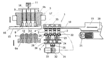
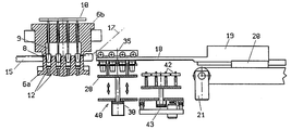
도1은 열성형기의 일부 단면도와 이 열성형기와 협동하는 열성형된 피가공물을 위한 꺼냄(extraction) 및 가공장치의 꺼냄 플레이트가 열성형길부터 꺼내진 직후의 1조(組)의 열성형피가공물을 가공하기 위한 장치로 이동된 상태를 나타내는 개략적인 측면도.Figure 1 shows a partial cross-sectional view of a thermoforming machine and an extraction for a thermoformed workpiece cooperating with the thermoforming machine and a pair of thermoformed pellets immediately after the take- Fig. 8 is a schematic side view showing a state in which the workpiece is moved to an apparatus for processing the workpiece.
도 2는 도 1의 부분확대도.2 is a partially enlarged view of Fig.
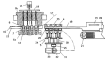
도 3은 도 1과 유사한 것으로 꺼냄 및 가공 장치가 직전(直前)의 조(組)의 피가공물의 가공을 행하고 있는 사이 열성형기가 그 작업 사이클의 나머지 부분, 즉 다음 조의 피가공물의 열성형작업을 행하고 있는 상태를 나타낸 개략적인 측면도.Fig. 3 is a schematic view similar to Fig. 1, in which a thermoforming machine for processing a workpiece in a set immediately preceding (immediately before) a workpiece is moved to the remainder of its work cycle, And Fig.
도4는 도 3의 부분 확대 단면도.4 is a partially enlarged cross-sectional view of Fig.
도 5는 열성형기와 이에 협동하는 꺼냄 및 가공장치의 양방이 새로운 작업 사이클을 개시하는 상태를 나타내는 부분 단면측면도.5 is a partial cross-sectional side view showing a state in which both the thermoforming machine and the ejection and processing device cooperating therewith start a new working cycle.
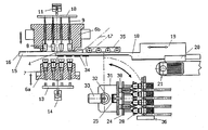
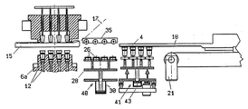
도 6은 열성기로부터 피가공물을 꺼내는 꺼냄 플레이트(extraction plate)에 의해 지지되고 운송된 1조의 피가공물을 가공하기 위한 2개의 연속된 작업 스테이션을 구비한 열성형기와 협동하는 다른 실시형태와 관한 꺼냄 및 가공장치의 일부 단면 측면도.6 shows another embodiment cooperating with a thermoforming machine having two consecutive work stations for machining a set of workpieces supported and transported by an extraction plate for taking out workpieces from a thermo-mechanical device. And a partial cross-sectional side view of the machining apparatus.
도 7은 피가공물을 열성형기로부터 꺼내어지는 꺼냄 플레이트에 의해 운송 및 지지된 1조의 피가공물을 가공하기 위한 작업공정을 나타내는 도 6과 유사한 도면.7 is a view similar to Fig. 6 showing a working process for machining a set of workpieces transported and supported by an ejection plate from which a workpiece is taken out of the thermoforming machine.
도 8은 피가공물을 열성형기로부터 꺼내는 꺼냄 플레이트에 의해 지지 운송된 1조의 피가공물을 가공하기 위한 작업 공정을 나타내는 도 6과 유사한 도면.Fig. 8 is a view similar to Fig. 6, showing a working process for machining a set of workpieces supported and carried by an ejection plate for taking out the workpieces from the thermoforming machine;
도 9는 피가공물을 열성형기로부터 꺼내는 꺼냄 플레이트에 의해 지지 운송된 1조의 피가공물을 가공하기 위한 작업공정을 도시한 도6과 유사한 도면.Fig. 9 is a view similar to Fig. 6 showing a working process for machining a set of workpieces supported and carried by an ejection plate for taking out the workpieces from the thermoforming machine;
도 10은 열성형기와 서로 작동하도록 구성된 한 쌍의 피가공물을 꺼내고 지지 및 운송 플레이트을 구비한 복수 조의 피가공 공작물용의 꺼냄 및 가공장치의 개략적인 평면도.10 is a schematic plan view of a plurality of sets of workpieces for workpieces to be machined and a pair of workpieces configured to operate with each other and having support and transfer plates;
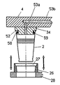
도 11은 컬링(curling)가공이 가능한 꺼냄 흡인 플레이이드 상에서 피가공물이 대응의 성형 장치와 맞물리 상태의 열성형된 피가공물의 부분확대 단면도.11 is a partially enlarged cross-sectional view of a thermoformed workpiece in a state where the workpiece is in engagement with a corresponding forming device on a take-away platen capable of curling.
도 12는 피가공물의 내측면에 작용하는 탄성 유지 링을 구비한 대응의 성형 장치를 나타내는 도 11과 유사한 도면.12 is a view similar to Fig. 11 showing a corresponding molding apparatus with an elastic retaining ring acting on the inner side of the workpiece; Fig.
도 13은 열성형된 피가공물을 유지하기 위한 흡인 수단을 구비한 성형장치를 나타내는 도 12와 유사한 도면.13 is a view similar to Fig. 12 showing a molding apparatus with suction means for holding a thermoformed workpiece; Fig.
도 14는 피가공물의 저부로의 천공작업을 가능하게 하기 위한 피가공물의 외측면에 작용하는 유지수단에 의해 꺼냄 플레이트상에 위치 유지된 상태의 열성형된 피가공물의 단면도.14 is a cross-sectional view of a thermoformed workpiece held in position on an ejection plate by retaining means acting on the outer surface of the workpiece to enable piercing work to the bottom of the workpiece;
도면 중, 동일 또는 유사의 부재 또는 컴퍼넌트는 동일한 참조번호로 나타내었다. 우선, 도 1-5에 나타나 있는 실시형태에 있어서, 열성형기 또는 프레스(3)에 의해 열성형된 피가공물 또는 가공대상물(비커, 트레이, 컵, 커피겁등의 일반적으로 유저(有低)에서 중공의 용기)(2)용의 꺼냄 및 가공장치(1)는 상기 열성형기(3)와 동기하여 그 열성형기(3)의 자웅 양형이 개방된 상태(도 1 및 도 5)에 있어서,1조의 열성형된 피가공물(2)을 꺼내는 꺼냄위치와, 상기 1조의 피가공물 전부를 협동하는 상기 열성형기(3)의 1개의 완전한 동작 사이클의 나머지 부분의 사이에 있어서, 가공 또는 취급하는 작업 스테이션(5)(도 1 및 도2)사이에서 이동하도록 구성된 꺼냄플레이트(4)를 가지고 있다.In the drawings, the same or similar members or components are denoted by the same reference numerals. First, in the embodiment shown in Figs. 1-5, a workpiece or a workpiece (a beaker, a tray, a cup, a coffee scarf or the like), which is thermoformed by a thermoforming machine or a
상기 열성형기(3)는 예를들면, 당해기술에 있어서 주지되어 있듯이, 하측에 위치하는 싱글 또는 더블의 자형(6a)과 이에 대응하는 상측의 웅형(6b)을 가지고 있는 프레스기이다. 상기 양형내의 적어도 일방은 이들 2개의 형이 함께 폐쇄위치와, 각각 주기적으로 서로 분리하는 개방위치와 수직이동하는 것이 가능한 상태로 지지되어 있다. 상기 단수 또는 복수의 자형(6a)에는 각각의 축심방향으로 이동가능하게 상기 웅형(6b)에 지지된 플러그(8)와 축심방향으로 위치 맞추어진 복수의 요부(凹)(7)가 형성되어 있다. 상기 플러그(8)는 상기 몰드가 폐쇄될 때(도 3)에 각각 대응의 요부(7)가 진입한다. 또한, 이들 플러그(8)는 각각 예를들면, 유체 구동식 피스턴 또는 실린더 장치(11)등의 리니어 액츄에이터로 구성되어 있는 단수 또는 복수의 액츄에이터 장치에 의해 작동되는 제어 프레임(10)에 그 상부가 접속된 수직 제어로드(9)에 의해 지지되어 있다.The
상기 단수 또는 복수의 자형(6a)에 형성된 각 요부(7)에는 또한 대응의 꺼냄부재(리프터)(20)가 설치되어 있어서 이는 상기 몰드가 개방되어 있는 상태(도1)에 있어서, 적당한 리이어 및 액츄에이터(14)에 의해 그 기타의 부재와 동시에 프레임(13)을 개재하여 작동되어서 대응의 요부(7)상방으로 그 내부에 형성된 열성형된 피가공물을 들어 올린다. 또한, 시이트 상(狀)의 열성형가능 재료(16)를 공급함과 동시에 각 열성형작업으로부터 발생하는 그 폐기물(17)를 상방으로 이동시켜서 상기 프레스기(3)로부터 제거하도록 구성된 예를들면 체인 형식의 피더(컨베이어)의 한쌍의 세로부재(15)가 상기 양 자형 및 웅형(6a, 6b)에 따라서 설치되어 있다. 상기 꺼냄 플레이트(4)는 어떠한 타입의 것으로도 좋고 예를들면, 출원인에 의해 1994년 9월 14일에 출원된 이탈리아국 특허출원 VR94A000082호 명세서에 개시되고 각 성형작업으로부터 형성된 복수의 피가공물에 대하여 작용하는 부압식 유지수단 또는 기계식 고정 수단을 사용한 타입의 것으로도 할 수가 있다.A corresponding pull-out member (lifter) 20 is also provided in each of the
보다 구체적으로는, 상기 꺼냄 플레이트(4)는 단수 또는 복수의 지지암(18)의 일단에 캔티레버(cantilever)상으로 지지되어 있다. 이 지지암(18)의 타단부는 예를들면, 감속기어 부착 모터(21)에 의해 제어되는 랙크(rack)식의 가이드 수단(20)상에서 요동 또는 운동가능하게 탑제된 캐리지 또는 슬라이드(19)에 접속되고 또는 이들로부터 일체적으로 되어 있다. 상기 감속 기어 부착 장치(21)는 상기 열성형기(3)의 작동 사이클과 동기하여 상기 자형 및 웅형(6a, 6b)이 개방된 상기 꺼냄위치와 상기 프레스기(3)에 근접하여 설치된 작업 스테이션(5)사이에서 왕복 사이클 운동을 제공하도록 구성되어 있다. 상기 작업 스테이션(5)은 상기 꺼냄 플레이트(4)에 의해 지지되어 아직 열을 보유하고 있는 상태의 각 성형작업으로부터 형성된 복수의 피가공물(2)를 컬링하기 위한 적당한 타입의 컬링가공 장치를 가지고 있다. 이 목적을 위해, 상기 작업 스테이션(5)은 성형 작업으로 형성되고 꺼냄 플레이트(4)에 의해 픽업(pick up)된 각 피가공물(2)의 바닥을 받아들여 지지하는 복수의 시트(22)를 가지고 있다. 이 시트(22)는 각각 그 일단부가 로드(23)에의해 지되어 있다. 그리고, 이 시트(22)중의 복수의 로드(23)의 타단부는 1개의 공통 프레임(24)에 고정되고 이 프레임(24)이 상기 로드(23)를 연장위치와 퇴각위치사이에서 구동하도록 구성된 유체 구동식 피스톤 및 실린더 장치(25)에 의해 제어된다. 그 전단부의 1개가 환상 컬링(curling)형상 또는 윤곽(27)(도4)을 구비한 환상부재(26)는 상기 시트(22)의 축심주위에 길이방향으로 이동가능 하며, 상기 환상부재(26)의 타단부는 상기 각 시트(22)에 대응하는 위치에 각각의 시트(22)의 자유통과를 허용하는 직경을 가지는 관통구멍(29)이 형성된 지지 플레이트(28)에 고정되어 있다. 상기 프레임(24)에 면하는 상기 지지 플레이트(28)의 면은 예를들면, 상기 유체구동식 피스톤 및 실린더 장치(25)를 탑재하여 두고. 그 전체를 참조번호 31로 표시된 지지구조체에 의해 지지된 한 쌍의 유체구동식 피스톤 및 실린더 장치(30)등의 단일 또는 복수의 적당한 리니어 액츄에이터에 접속되어 있다.More specifically, the
상기 지지구조체(31)는 감속기어 부착 모터 장치(33)(도3)의 작용에 의해 상기 로드(23)의 축심의 방향에 대하여 수직한 축심(32)주위로 예를 들어 90도 회전할수가 있다. 각각이 대응의 환상 컬링부재(27)중에 끼울수 있는 적당한 컬링으로서의 에지 성형구(34)가 상기 꺼냄 플레이트(4)의 상기 자형(6a)에 따라서 작업스테이션(5)에 대향하는 면에 설치되어 있다. 이 성형구(34)는 우선 상기 꺼냄 플레이트(4)가 상기 꺼냄위치에 있는 상태에서 자형(6a)로부터 떼어진 각각의 피가공물(2)의 림의 내측면에 맞물리고 이에 계속하여 이들에 대하여 상기 유체구동장치(30)에 의해 드러스트된 대응의 환상부재(26)와 협동하여 작업스테이션(5)에 있어서, 상기 피가공물(2)의 컬링상의 림을 형성한다. 상기 유체구동식 피스톤 및실리더 장치(30)의 드러스트에 저항하여 상기 꺼냄플레이트(4)는 작업 스테이션(5)에 있어서 예를들면 캐리지(35)에 따라서 위치하고 이 캐리지(35)는 상기 컬링공정 또는 에지 형성 공정간의 항력을 극복하지만, 꺼냄플레이트(4)의 꺼냄위치와 작업스테이션(5)사이의 이동에 대하여 어떠한 방해가 없다.The
상술한 꺼냄 수단의 작동수순은 극히 단순하다. 즉, 자형 및 웅형(6a, 6b)이 개방되어 있는 상태에서, 꺼냄 장치(12)는 자형(6a)의 대응의 요부(7)로부터 형성된 피가공물(2)을 떼어낸다. 이 사이에 꺼냄 플레이트(4)가 상기 꺼냄위치로의 이동을 개시한다(도 5). 프레스기(3)가 완전히 개방될 때에는 피가공물(2)은 대응의 에지 성형구(34)에 끼워지게 되고 작업 스테이션(5)로 운송되고 동시에 폐기물(17)이 떼어져서 프레스기(3)가 닫히기 시작한다(도1).The operation procedure of the above-described pulling means is extremely simple. That is, in a state in which the female and
작업 스테이션(5)에 있어서 상기 유체구동식 피스톤 및 실린더 장치(25, 30)가 작동하여 각 피가공물(2)이 대응의 에지 성형(34)에 깊게 세트되도록 시트(22)를 피가공물(2)의 저부에 누름과 동시에 에지 성형구(34)가 대응의 이 에지 성형구(34)에 의해 고정된 피가공물(2)의 외측에지에 눌러진다. 그리고, 이 피가공물(2)자신이 자형(6a)에 있어서와 같은 상호간격 및 배치에 꺼냄 플레이트(4)에 고정된 상태에서(도3), 이 피가공물을 구성하는 열가소성재료의 고온에 있어서의 가공성과 또한 피가공물(2)에 남아있는 적당한 양(일반적으로, 상기 열가공성의 임계치보다도 충분히 높은)의 잔여의 열성형용의 열을 이용하여 이 에지를 컬링가공하는 것이다. 이와 같이 하여 에지 성형작업이 완료되면, 피가공물(2)은 예를들면, 각각 분출유 또는 공기 혹은 그 기타의 적당한 해제수단에 의하여 상기 꺼냄 플레이트(4)로부터 해제되고 시트(22)에 받아들여 진다. 계속하여 상기 유체 구동식 피스톤 및 실린더 장치(25)의 작동에 의해 상기 유체구동식 피스톤 및 실린더 장치(30)의 작동과 상기 지지구조체(31)의 90도 회전에 따라 환상부재(26)과 함께 꺼냄 플레이트(4)로부터 떼어진다. 감속기어부착 모터장치(33)의 작동에 의해 도 5에 있어서 참조번호 36으로 그 전체을 나타내는 스택커에 운반되고 당해기술에 있어서 통상 행해지는 것처럼 적층 스택된다.In the
도 6-9에 나타난 실시예에 있어서는, 상기 작업스테이션(5)은 2개의 작업 스테이션, 즉 예들들면, 유체구동식 피스톤 및 실린더 장치(30)에 의해 제어되는 복수의 환상 에지 성형구(26)를 가지는 에지성형 작업 스테이션(40)과, 예를들어, 피가공물(2)의 저부를 천공하기 위한 천공작업 스테이션(41)에 의해 치환되어 있다. 피가공물(2)을 픽업한 후 꺼냄 플레이트(4)는 이 피가공물(2)을 부착한 상태에서 작업 스테이션(40)에 있어서 제 1정지를 행하고 여기서 모든 피가공물(2)이 꺼냄 플레이트(4)에 부착된 상태에서 에지 성형 가공된다(도 6 및 7). 그후 천공 작업 스테이션(41)에서 제 2 정지를 행하여 여기서 복수의 천공구(42)(각 형(型組)의 각각의 피가공물(2)에 대하여 1개씩)가 유체구동장치(43)의 리니어 액츄에이터로부터의 드러스트에 의해 이 피가공물(2)의 저부를 천공한다(도8 및 도9). 천공작업 후, 꺼냄 플레이트(4)는 피가공물(20)을 해제하고 상기 꺼냄위치로 되돌아와 다음 작업 사이클들 개시한다. 한편, 천공된 피가공물(2)은 천공작업 스테이션(41)으로부터 적당한 방법으로 떼어내어서 스택되거나 또는 그의 기타의 처리를 받는다. 도 10은 또한 다른 실시형태을 나타내고 여기서는 2개의 꺼냄 플레이트(4a, 4b)가 1대의 프레스기(3)과 협동하고 이 2개의 꺼냄 플레이트(4a, 4b)는 상기 꺼냄위치로 서로 이동하여 이에 의해 형으로 떼어내어진 직후의 피가공물(2)을 이 플레이트에 부착하기 까지의 상태에서, 3회분연속하여 취급 및 가공가능하도록 구성되어 있다. 이 목적을 위하여, 각 꺼냄 플레이트(4a, 4b)는 대응의 지지암(45)의 일단부에 부착되고 이 지지 암(45)의 타단부는 대응하는 꺼냄 플레이트가 위치하는 평면에 대하여 수직한 길이방향 축심을 가지는 핀부재(46)에 고정되어 있다. 이 핀부재(46)는 예를들면 감쇠기어 부착 모터장치(47)등의 액츄에이터 수단에 의해 제어되고 회전운동하여 상기 대응의 꺼냄 플레이트를 꺼냄 위치와 제 1작업 스테이션 예를들면, 에지 형성 또는 컬링가공 스테이션(40)사이로 이동시킨다. 그 대응의 핀 부재(46)와 함께 각 감쇠기어부착 모터 장치(47)는 가이드(48)위에서 이동가능 하도록 이동 가능하게 부착되어 있음과 더불어, 또한 이 가이드(48)에 따라서 감속기어부착 모터 장치(50)에 의해 구동되는 일정 길이의 체인등으로 구성되어 있는 리니어 액츄에이터에 의해 이동된다.6-9, the
상기 구성에 의하면, 각 꺼냄 플레이트(4a, 4b)는 꺼냄위치로 이동하여 자형(6a)으로부터 1조 또는 1회의 성형작업분의 피가공물(2)을 픽업하고 이들 피가공물을 각각의 지지 암(45)의 회전에 의해 제 1작업 스테이션으로서의 에지 성형 및 컬링 가공 스테이션(40)에 이동하고 다음에 각각의 가이드(48)에 따라서 이동하는 것에 의해 제 2작업 스테이션, 예를들면, 천공 스테이션(43)으로 이동된다. 그 사이에 타방의 꺼냄 플레이트가 꺼냄위치로 이동한다.According to the above arrangement, each of the
도 11-14는 꺼냄 플레이트(4)의 다른 실시형태를 보여준다. 도 11은 플러그로서의 복수의 에지 형성구 (34)를 구비한 꺼냄 플레이트(4)을 나타낸다. 상기 성형구 또는 플러그(34)는 열성형된 피가공물(2)의 에지가 맞닿을 수 있는 주부 쇼울더(52)를 가지고 있다. 상기 각 에지 성형구(34)는 예를들면, 전동밸브(55)에 의해 닫는 것이 가능한 덕트(54)를 개재하여 전동 모터(57)에 의해 조작된 흡인펌프(56)와 연통가능한 상태에서, 예를들면, 상기 꺼냄 플레트(4)의 본체에 형성된 주 구멍(53b)과 연통하는 단수 또는 복수의 축심방향의 구멍(53a)을 가지고 있다. 꺼냄공정 중에 꺼냄 플레이트(4)가 피가공물(2)을 이동시킬 때에, 상기 성형구(34)는 흡인 펌프(56)와 연통되어서 각 피가공물의 일부분을 강제 흡입하고 이를 상기 에지 성형구의 상기 쇼울더(52)에 눌러진다. 피가공물(2)이 각 조작 스테이션으로 이동된 후, 상기 전동 펌프(55)를 예를들면 도시하지 않은 프로그램 콘트롤러에 의해 제어되어 상기 덕터를 주위분위기와 연통시키고 이에 의해 각 피가공물중에 있어서의 그때 까지의 부압에 의한 유지작용을 해제한다. 이 결과, 피가공물(2)을 꺼냄 플레이트(4)로부터 해제, 떼어내어 지는 것이 가능하다.Figs. 11-14 show another embodiment of the
도 12에 나타난 실시형태에 있어서, 에지성형구(34)의 쇼울더(52)는 피가공물(2)의 내측면에서 떼어져서 가능하게 맞물리도록 구성된 탄성 립 시일(lip seal)(59)용의 시트로서 역할을 하는 환상홈(58)을 구비하고 있다. 이 구성의 경우, 피가공물을 각각의 플러그에 유지시키기 위해 피가공물(2)내부에 부압을 만들 필요는 없고 흡인 펌프(56)는 피가공물(2)의 가공작업 완료 후에, 이 피가공물을 꺼냄 플레이트(4)로부터 떼어 내기 위해 공기흐름을 송출하는 압력 타입의 것으로 되어 있다.12, the
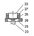
도 13에 나타난 실시형태에 있어서는 피가공물(2)을 각각의 에지 성형구(34)에 유지 시키기 위한 수단이 설치되어 있어서 이는 각 에지 성형구(34)에 형성된 상방 요부(61)내부에 설치되어 있고 스프링(62)의 부하력(loading force)에 대향하여 이동가능 한 단수 또는 복수의 흡인 컵(60)으로 구성되어 있다. 각 흡인컵(60)은 도 11의 실시형태와 전체적으로 마찬가지로 흡인 펌프(56)와 연통하고 있다. 꺼냄 플레이트(4)위에 유지된 피가공물(2)의 하방에는 플레이트(70)가 나타나 있으고 이는 피가공물(2)에 대하여 근접 이간 이동 가능하게 이 피가공물의 저부의 위측에 라벨(71)을 첩부하도록 구성되어 있다.In the embodiment shown in Fig. 13, means for holding the
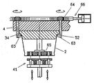
도 14는 각 에지 성형구(34)에 피가공물(2)을 유지시키기 위한 수단의 다른 실시형태를 나타낸다. 이는 각각의 제어부재(64)로부터 캔틸레버상으로 돌출한 2개이상의 돌기(63)로 구성되어 있어서 상기 제어부재(64)는 상기 꺼냄 플레이트(4)에 회전가능하게 부착됨과 더불어, 양 방향으로 부분회전 이동하여(예를들면, 참조번호 66으로 나타낸 적당한 리니어 액츄에이터에 의해 작동되는 랙크 메커니즘에 의해)이에 의해서 그 대응의 돌기(63)를 성형구의 주부 쇼울더(52)에 향하여 맞물림 위치로 이동시키거나 혹은 이 주부 쇼울더(52)로부터 떨어져서 비맞물림위치로 이동시킨다. 이 구성은 피가공물(2)의 외측으로부터 꺼냄플레이트(4)에 유지시킨는데에 특히 유리하다. 도 14에서는 또한 피가공물(2)의 저부를 천공하는 장치(41)가 개략적으로 나타나 있다. 피가공물의 내부에서는 각 에지 성형구가 이 피가공물의 저부에 형성된 각각의 구멍에 대응하는 축심방향의 구멍을 구비한 대응의 헤드(65)를 지지하고 있다. 이 헤드(65)는 피가공물의 저부를 지지하여 이 피가공물의 저부을 변경을 방지하는 드러스트 플레이트로서 작용함과 아울러, 드릴링 비트(driling bit)용의 가이드로써도 작용한다.Fig. 14 shows another embodiment of the means for holding the
상술된 취출 가공 장치에 의하면, 1조 또는 1회의 성형작업분의 복수의 열형성된 피가공물에 대하여 이 프레스기로부터 떼어내기 직후에 있어서, 열성형기의 단수 또는 복수의 열성형 사이클중에 단수 또는 복수의 가공작업을 용이 또는 확힐히 행하는 것이 가능하다는 것이 이해해도 좋다. 상술된 꺼냄 가공장치는 특허청구의 범위에 기재된 권리범위내에서 그 기타 각종 변경 및 개조가 가능하다. 따라서, 예를 들면, 이 장치는 자형이 상방으로 배치된 웅형이 상방으로 배치되어 이 양방의 형이 1개의 수평면에 따라서, 이동하는 타입의 프래스기도 사용가능하다. 또한 작업 스테이션은 피가공물을 살균하기 위한 각종 장치을 구비하여도 좋다.According to the above-described take-out processing apparatus, a plurality of thermally processed workpieces for one set or one molding operation are removed from the press machine, and a single or a plurality of processes It can be understood that it is possible to perform the operation easily or securely. The above-described machining apparatus can be variously modified and modified within the scope of the claims described in the claims. Therefore, for example, this apparatus can be used as a type of a type in which a male having a shape of an upper side is arranged upward, and a type of both of the types moving along one horizontal plane. The work station may also be equipped with various devices for sterilizing the workpiece.
이상, 본 발명에 의해, 열성형된 피가공물을 열성형기의 형에서 떼어내어 이 피가공물에 대하여 취출 공정의 직후에 열성형기의 사이클중에 있어서 가공 공정을 행하는 것이 가능하고 더구나 취출 가공 장치를 웅형과 그 상방 또는 하방에 위치된 웅형을 구비한 열성형기에 적응하도록 구성될수 가 있고 또한 신뢰성과 생산성인 높은 취출 가공 장치를 제공하는 것이 가능했다.As described above, according to the present invention, it is possible to remove the thermoformed workpiece from the die of the thermoforming machine, to perform the machining process during the cycle of the thermoforming machine immediately after the takeout process for the workpiece, It has been possible to provide a high take-out processing apparatus that can be configured to accommodate a thermoforming machine having a male pattern located above or below it and which is also reliable and productive.
Claims (11)
Applications Claiming Priority (2)
| Application Number | Priority Date | Filing Date | Title |
|---|---|---|---|
| IT96VR000052A IT1289111B1 (en) | 1996-05-28 | 1996-05-28 | EQUIPMENT FOR COLLECTING AND PROCESSING THERMOFORMED OBJECTS FROM A THERMOFORMING MACHINE |
| ITVR96A000052 | 1996-05-28 |
Publications (2)
| Publication Number | Publication Date |
|---|---|
| KR970073773A KR970073773A (en) | 1997-12-10 |
| KR100443473B1 true KR100443473B1 (en) | 2004-11-03 |
Family
ID=11428206
Family Applications (1)
| Application Number | Title | Priority Date | Filing Date |
|---|---|---|---|
| KR1019970020607A Expired - Lifetime KR100443473B1 (en) | 1996-05-28 | 1997-05-26 | A device for taking out and thermoforming a workpiece from a thermoforming machine |
Country Status (19)
| Country | Link |
|---|---|
| US (1) | US6042360A (en) |
| EP (1) | EP0810079B1 (en) |
| JP (1) | JPH1052859A (en) |
| KR (1) | KR100443473B1 (en) |
| CN (1) | CN1082434C (en) |
| AT (1) | ATE194795T1 (en) |
| AU (1) | AU729011B2 (en) |
| BR (1) | BR9703319A (en) |
| CA (1) | CA2206186C (en) |
| DE (1) | DE69702572T2 (en) |
| DK (1) | DK0810079T3 (en) |
| ES (1) | ES2150190T3 (en) |
| GR (1) | GR3034589T3 (en) |
| HU (1) | HU222549B1 (en) |
| IT (1) | IT1289111B1 (en) |
| NO (1) | NO311755B1 (en) |
| PL (1) | PL183311B1 (en) |
| PT (1) | PT810079E (en) |
| RO (1) | RO118644B1 (en) |
Families Citing this family (23)
| Publication number | Priority date | Publication date | Assignee | Title |
|---|---|---|---|---|
| US6334766B1 (en) * | 1995-12-22 | 2002-01-01 | Mccormick John | Takeout apparatus for shuttle-type plastic blow moulding machines |
| IT1293955B1 (en) * | 1997-06-13 | 1999-03-11 | Isap Omv Group Spa | PLATE DEVICE FOR PICK UP AND REMOVAL OF A PRINT OF THERMOFORMED OBJECTS FROM A THERMOFORMING PRESS |
| DE19812414C2 (en) * | 1998-03-20 | 2003-12-18 | Walter Lauermann | Receiving device for series products, in particular plastic cups |
| DE19933355C1 (en) * | 1999-07-16 | 2001-03-15 | Illig Maschinenbau Adolf | Method for stacking containers made of thermoplastic material and device for carrying out the method |
| FR2811932B1 (en) * | 2000-07-20 | 2003-05-16 | Oreal | METHOD FOR MANUFACTURING A BELLOWS |
| ITVR20010017A1 (en) | 2001-02-15 | 2002-08-16 | Isap Omv Group Spa | HANDLING EQUIPMENT OF PILE GROUPS OF PERMANENT THERMOFORMED OBJECTS KEEP IN CORRECT AXIAL STRUCTURE |
| ITVR20010016A1 (en) | 2001-02-15 | 2002-08-16 | Isap Omv Group Spa | PROCESS AND HANDLING SYSTEM FOR THERMOFORMED OBJECTS FOR SINGLE STATION THERMOFORMING MACHINE WITH SHAPE AND SHAPE MOLD |
| ITVR20010018A1 (en) * | 2001-02-15 | 2002-08-16 | Isap Omv Group Spa | STACKING SYSTEM OF STACKS OF THERMOFORMED OBJECTS FROM A WELDING CAGE TO A REMOVAL CONVEYOR |
| US6918753B2 (en) * | 2001-11-15 | 2005-07-19 | G.N. Plastics Company Ltd. | Dual-mold thermoforming press |
| WO2004041515A1 (en) * | 2002-11-01 | 2004-05-21 | Sencorp Systems, Inc. | Robotic method and apparatus for removing parts from the trim press of a thermoforming system |
| EP1651414A1 (en) * | 2003-08-01 | 2006-05-03 | Graham Packaging Company, L.P. | Mold mounted drop cylinder assembly |
| WO2007034176A2 (en) * | 2005-03-18 | 2007-03-29 | Pvaxx Research And Development Limited | Unloading apparatus for rotationnaly moulded articles, and unloading method related thereto |
| GB2425506B (en) | 2005-04-26 | 2010-11-10 | Pvaxx Res & Dev Ltd | Load carrying apparatus and method of manufacture |
| DE102005026687B4 (en) * | 2005-06-09 | 2017-05-24 | Kiefel Gmbh | Method and device for stacking thermoformed articles |
| US20080054525A1 (en) * | 2006-09-06 | 2008-03-06 | Graham Packaging Company, Lp | Method and apparatus for stretching the neck finish of a molded plastic article |
| US7586056B2 (en) * | 2006-09-15 | 2009-09-08 | Shin-Etsu Polymer Co., Ltd | Resin molded body, receiving jig and method for manufacturing push button switch member |
| DE202008003710U1 (en) * | 2008-03-15 | 2009-08-06 | Krones Ag | Device for transporting hollow body preforms |
| DE102008019988B3 (en) * | 2008-04-21 | 2009-06-25 | Illig Maschinenbau Gmbh & Co. Kg | Method for separating deep-drawn molded sections, involves encompassing gripper by gripping flange of molded sections after punching operation |
| US20100126901A1 (en) * | 2008-11-24 | 2010-05-27 | Alain Cerf | Thermofrom a tray insitu with an article |
| UA113527U (en) * | 2011-09-16 | 2017-02-10 | DEVICES FOR THERMAL PRODUCT MAKING | |
| ITVR20110198A1 (en) * | 2011-10-27 | 2013-04-28 | Omv Machinery S R L | THERMOFORMING PRESS AND THERMOFORMATURACON PROCEDURE IT CAN BE REALIZED |
| ES2625252B1 (en) * | 2016-01-18 | 2018-04-24 | Comercial de Útiles y Moldes, S.A. | Device for the demoulding of parts and mold comprising said device |
| US20210069917A1 (en) * | 2019-09-10 | 2021-03-11 | Brian Charles Cloetingh | Grippers to pick plastic sleeved cups for case cartoning using industrial and collaborative robots |
Family Cites Families (10)
| Publication number | Priority date | Publication date | Assignee | Title |
|---|---|---|---|---|
| US3561058A (en) * | 1968-04-04 | 1971-02-09 | Henry Komendowski | Rim shaping and trimming apparatus for plastic containers and the like |
| IT1071029B (en) * | 1976-12-06 | 1985-04-02 | O M V Spa Off Mec | AUTOMATIC EXTRACTION DEVICE FROM A STACKING STACKING STATION OF FINISHED CABLES OBJECTS, THERMOFORMED FROM A PLASTIC SHEET |
| IT1175178B (en) * | 1983-11-15 | 1987-07-01 | Omv Spa Off Mecc Veronese | EXTRACTOR OF OBJECTS OBTAINED WITH THERMOFORMING MACHINES |
| CN85103810B (en) * | 1985-05-14 | 1988-01-06 | 办公机器公司 | Extractor for workpieces of hot forming device |
| IT1218634B (en) * | 1987-06-05 | 1990-04-19 | Omv Spa Off Mecc Veronese | PROCEDURE FOR THE CREATION OF A DEPRESSION IN ROOMS FORMED BETWEEN A FLAT PLATE EXTRACTOR AND THERMOFORMED CABLE OBJECTS |
| DE3928301A1 (en) * | 1989-08-26 | 1991-02-28 | Illig Maschinenbau Adolf | Demoulding device for thermo-formed items - lifts mouldings first on to locking features on holes in horizontal plate which then slides sideways for mouldings to be pressed off |
| IT1236862B (en) * | 1989-12-18 | 1993-04-22 | Omv Spa | PROCEDURE FOR THE EDGE TRAINING OF CONTAINERS IN SYNTHETIC THERMOPLASTIC MATERIAL, OPEN UPWARD AND ENDING WITH AN EXTERNAL FLANGE BOWED UPWARD AND EXTENDING DOWNWARD AND MACHINE THAT MAKES IT |
| IT1257010B (en) * | 1992-02-03 | 1996-01-05 | Omv Spa | PROCESS AND EQUIPMENT FOR THERMOFORMING AND STACKING OF CABLE OBJECTS WITH BOTTOM STARTING FROM THERMOPLASTIC TAPE MATERIAL. |
| IT1257683B (en) * | 1992-10-28 | 1996-02-01 | Pietro Padovani | EDGE BANDING MACHINE PARTICULARLY FOR CABLE ITEMS OBTAINED BY THERMOFORMING STARTING FROM THERMOFORMABLE RIBBON MATERIAL |
| IT1268286B1 (en) * | 1994-09-14 | 1997-02-27 | Isap Omv Group Spa | THERMOFORMING EQUIPMENT FOR THERMOFORMABLE MATERIALS IN TAPE OR SHEET |
-
1996
- 1996-05-28 IT IT96VR000052A patent/IT1289111B1/en active IP Right Grant
-
1997
- 1997-05-23 PL PL97320154A patent/PL183311B1/en unknown
- 1997-05-26 KR KR1019970020607A patent/KR100443473B1/en not_active Expired - Lifetime
- 1997-05-27 AT AT97201608T patent/ATE194795T1/en active
- 1997-05-27 JP JP9135641A patent/JPH1052859A/en active Pending
- 1997-05-27 BR BR9703319A patent/BR9703319A/en not_active IP Right Cessation
- 1997-05-27 DK DK97201608T patent/DK0810079T3/en active
- 1997-05-27 DE DE69702572T patent/DE69702572T2/en not_active Expired - Lifetime
- 1997-05-27 US US08/864,001 patent/US6042360A/en not_active Expired - Lifetime
- 1997-05-27 ES ES97201608T patent/ES2150190T3/en not_active Expired - Lifetime
- 1997-05-27 AU AU23655/97A patent/AU729011B2/en not_active Ceased
- 1997-05-27 EP EP97201608A patent/EP0810079B1/en not_active Expired - Lifetime
- 1997-05-27 PT PT97201608T patent/PT810079E/en unknown
- 1997-05-27 NO NO19972403A patent/NO311755B1/en not_active IP Right Cessation
- 1997-05-27 RO RO97-00962A patent/RO118644B1/en unknown
- 1997-05-27 CA CA002206186A patent/CA2206186C/en not_active Expired - Lifetime
- 1997-05-27 CN CN97113199A patent/CN1082434C/en not_active Expired - Lifetime
- 1997-05-28 HU HU9700964A patent/HU222549B1/en not_active IP Right Cessation
-
2000
- 2000-10-11 GR GR20000402278T patent/GR3034589T3/en not_active IP Right Cessation
Also Published As
| Publication number | Publication date |
|---|---|
| CN1082434C (en) | 2002-04-10 |
| CA2206186C (en) | 2007-04-24 |
| DE69702572D1 (en) | 2000-08-24 |
| PL320154A1 (en) | 1997-12-08 |
| EP0810079A1 (en) | 1997-12-03 |
| RO118644B1 (en) | 2003-08-29 |
| DK0810079T3 (en) | 2000-11-06 |
| CA2206186A1 (en) | 1997-11-28 |
| NO972403D0 (en) | 1997-05-27 |
| BR9703319A (en) | 1998-09-15 |
| PL183311B1 (en) | 2002-06-28 |
| GR3034589T3 (en) | 2001-01-31 |
| MX9703878A (en) | 1998-06-30 |
| CN1168315A (en) | 1997-12-24 |
| ITVR960052A1 (en) | 1997-11-28 |
| JPH1052859A (en) | 1998-02-24 |
| HU222549B1 (en) | 2003-08-28 |
| ITVR960052A0 (en) | 1996-05-28 |
| HUP9700964A2 (en) | 1997-12-29 |
| AU729011B2 (en) | 2001-01-25 |
| KR970073773A (en) | 1997-12-10 |
| EP0810079B1 (en) | 2000-07-19 |
| ES2150190T3 (en) | 2000-11-16 |
| DE69702572T2 (en) | 2001-04-19 |
| HUP9700964A3 (en) | 1999-03-01 |
| NO311755B1 (en) | 2002-01-21 |
| IT1289111B1 (en) | 1998-09-25 |
| PT810079E (en) | 2001-01-31 |
| ATE194795T1 (en) | 2000-08-15 |
| NO972403L (en) | 1997-12-01 |
| AU2365597A (en) | 1997-12-04 |
| US6042360A (en) | 2000-03-28 |
| HU9700964D0 (en) | 1997-07-28 |
Similar Documents
| Publication | Publication Date | Title |
|---|---|---|
| KR100443473B1 (en) | A device for taking out and thermoforming a workpiece from a thermoforming machine | |
| CA2087512C (en) | Method and apparatus for the thermoforming and stacking of hollow objects incorporating a base formed from thermoplastics sheet material | |
| JP2006504557A (en) | Side shuttle apparatus and method for injection molding machine | |
| JPH0686084B2 (en) | Molding equipment for molded products | |
| RU2127190C1 (en) | Method of production of hollow items, in particular plastic blanks, and device for its realization | |
| US4932856A (en) | Apparatus for thermoforming hollow articles | |
| EP0679141B1 (en) | Apparatus for removing hollow articles from a mould | |
| CA2199807C (en) | Thermoforming apparatus for thermoformable materials in ribbon or sheet-form | |
| CN212351088U (en) | Die casting processing and testing integrated machine | |
| IL124926A (en) | Plate device for withdrawing and moving a molding of thermoformed objects away from a thermoforming press | |
| RU2317202C2 (en) | Device and the method used for forming of the article with its part having the smaller cross-section | |
| CN103056213B (en) | Hot forming and cuts sheet material take out equipment and the method for waste material part in a mold | |
| CN212498960U (en) | Production device for encapsulating piston | |
| KR200186172Y1 (en) | Decoration film sticking machine | |
| EP0796167B1 (en) | Method and apparatus for loading labels into a mould of a thermoforming machine | |
| MXPA97003878A (en) | Apparatus to remove and process thermoformed objects from a thermoforming machine | |
| RU2174069C2 (en) | Device for removal and treatment of molded articles from plants for molding of sheet thermoplastics | |
| CN217474665U (en) | Feeding mechanism and disc spring recovery processing equipment | |
| CN220129414U (en) | Product taking-out and separating device | |
| CN219632506U (en) | Full-automatic nail beating equipment | |
| JP3112789B2 (en) | Molded article manufacturing apparatus and molded article manufacturing method | |
| CN110576544A (en) | Automatic positioning deburring mechanism |
Legal Events
| Date | Code | Title | Description |
|---|---|---|---|
| PA0109 | Patent application |
Patent event code: PA01091R01D Comment text: Patent Application Patent event date: 19970526 |
|
| PG1501 | Laying open of application | ||
| A201 | Request for examination | ||
| PA0201 | Request for examination |
Patent event code: PA02012R01D Patent event date: 20010625 Comment text: Request for Examination of Application Patent event code: PA02011R01I Patent event date: 19970526 Comment text: Patent Application |
|
| E902 | Notification of reason for refusal | ||
| PE0902 | Notice of grounds for rejection |
Comment text: Notification of reason for refusal Patent event date: 20030715 Patent event code: PE09021S01D |
|
| E701 | Decision to grant or registration of patent right | ||
| PE0701 | Decision of registration |
Patent event code: PE07011S01D Comment text: Decision to Grant Registration Patent event date: 20040529 |
|
| GRNT | Written decision to grant | ||
| PR0701 | Registration of establishment |
Comment text: Registration of Establishment Patent event date: 20040728 Patent event code: PR07011E01D |
|
| PR1002 | Payment of registration fee |
Payment date: 20040729 End annual number: 3 Start annual number: 1 |
|
| PG1601 | Publication of registration | ||
| PR1001 | Payment of annual fee |
Payment date: 20070711 Start annual number: 4 End annual number: 4 |
|
| PR1001 | Payment of annual fee |
Payment date: 20080709 Start annual number: 5 End annual number: 5 |
|
| PR1001 | Payment of annual fee |
Payment date: 20090716 Start annual number: 6 End annual number: 6 |
|
| PR1001 | Payment of annual fee |
Payment date: 20100719 Start annual number: 7 End annual number: 7 |
|
| PR1001 | Payment of annual fee |
Payment date: 20110712 Start annual number: 8 End annual number: 8 |
|
| PR1001 | Payment of annual fee |
Payment date: 20120716 Start annual number: 9 End annual number: 9 |
|
| FPAY | Annual fee payment |
Payment date: 20130701 Year of fee payment: 10 |
|
| PR1001 | Payment of annual fee |
Payment date: 20130701 Start annual number: 10 End annual number: 10 |
|
| FPAY | Annual fee payment |
Payment date: 20140701 Year of fee payment: 11 |
|
| PR1001 | Payment of annual fee |
Payment date: 20140701 Start annual number: 11 End annual number: 11 |
|
| PR1001 | Payment of annual fee |
Payment date: 20150701 Start annual number: 12 End annual number: 12 |
|
| FPAY | Annual fee payment |
Payment date: 20160630 Year of fee payment: 13 |
|
| PR1001 | Payment of annual fee |
Payment date: 20160630 Start annual number: 13 End annual number: 13 |
|
| EXPY | Expiration of term | ||
| PC1801 | Expiration of term |
Termination date: 20171126 Termination category: Expiration of duration |