KR20080102425A - Use of magnesium-copper composition for magnesium evaporation and magnesium distributor - Google Patents
Use of magnesium-copper composition for magnesium evaporation and magnesium distributor Download PDFInfo
- Publication number
- KR20080102425A KR20080102425A KR1020087024640A KR20087024640A KR20080102425A KR 20080102425 A KR20080102425 A KR 20080102425A KR 1020087024640 A KR1020087024640 A KR 1020087024640A KR 20087024640 A KR20087024640 A KR 20087024640A KR 20080102425 A KR20080102425 A KR 20080102425A
- Authority
- KR
- South Korea
- Prior art keywords
- magnesium
- evaporation
- copper composition
- container
- composition
- Prior art date
- Legal status (The legal status is an assumption and is not a legal conclusion. Google has not performed a legal analysis and makes no representation as to the accuracy of the status listed.)
- Granted
Links
Images


Classifications
-
- C—CHEMISTRY; METALLURGY
- C22—METALLURGY; FERROUS OR NON-FERROUS ALLOYS; TREATMENT OF ALLOYS OR NON-FERROUS METALS
- C22C—ALLOYS
- C22C9/00—Alloys based on copper
-
- C—CHEMISTRY; METALLURGY
- C23—COATING METALLIC MATERIAL; COATING MATERIAL WITH METALLIC MATERIAL; CHEMICAL SURFACE TREATMENT; DIFFUSION TREATMENT OF METALLIC MATERIAL; COATING BY VACUUM EVAPORATION, BY SPUTTERING, BY ION IMPLANTATION OR BY CHEMICAL VAPOUR DEPOSITION, IN GENERAL; INHIBITING CORROSION OF METALLIC MATERIAL OR INCRUSTATION IN GENERAL
- C23C—COATING METALLIC MATERIAL; COATING MATERIAL WITH METALLIC MATERIAL; SURFACE TREATMENT OF METALLIC MATERIAL BY DIFFUSION INTO THE SURFACE, BY CHEMICAL CONVERSION OR SUBSTITUTION; COATING BY VACUUM EVAPORATION, BY SPUTTERING, BY ION IMPLANTATION OR BY CHEMICAL VAPOUR DEPOSITION, IN GENERAL
- C23C14/00—Coating by vacuum evaporation, by sputtering or by ion implantation of the coating forming material
- C23C14/22—Coating by vacuum evaporation, by sputtering or by ion implantation of the coating forming material characterised by the process of coating
- C23C14/24—Vacuum evaporation
-
- C—CHEMISTRY; METALLURGY
- C22—METALLURGY; FERROUS OR NON-FERROUS ALLOYS; TREATMENT OF ALLOYS OR NON-FERROUS METALS
- C22C—ALLOYS
- C22C23/00—Alloys based on magnesium
-
- C—CHEMISTRY; METALLURGY
- C22—METALLURGY; FERROUS OR NON-FERROUS ALLOYS; TREATMENT OF ALLOYS OR NON-FERROUS METALS
- C22C—ALLOYS
- C22C23/00—Alloys based on magnesium
- C22C23/02—Alloys based on magnesium with aluminium as the next major constituent
-
- C—CHEMISTRY; METALLURGY
- C23—COATING METALLIC MATERIAL; COATING MATERIAL WITH METALLIC MATERIAL; CHEMICAL SURFACE TREATMENT; DIFFUSION TREATMENT OF METALLIC MATERIAL; COATING BY VACUUM EVAPORATION, BY SPUTTERING, BY ION IMPLANTATION OR BY CHEMICAL VAPOUR DEPOSITION, IN GENERAL; INHIBITING CORROSION OF METALLIC MATERIAL OR INCRUSTATION IN GENERAL
- C23C—COATING METALLIC MATERIAL; COATING MATERIAL WITH METALLIC MATERIAL; SURFACE TREATMENT OF METALLIC MATERIAL BY DIFFUSION INTO THE SURFACE, BY CHEMICAL CONVERSION OR SUBSTITUTION; COATING BY VACUUM EVAPORATION, BY SPUTTERING, BY ION IMPLANTATION OR BY CHEMICAL VAPOUR DEPOSITION, IN GENERAL
- C23C14/00—Coating by vacuum evaporation, by sputtering or by ion implantation of the coating forming material
- C23C14/06—Coating by vacuum evaporation, by sputtering or by ion implantation of the coating forming material characterised by the coating material
- C23C14/14—Metallic material, boron or silicon
-
- C—CHEMISTRY; METALLURGY
- C23—COATING METALLIC MATERIAL; COATING MATERIAL WITH METALLIC MATERIAL; CHEMICAL SURFACE TREATMENT; DIFFUSION TREATMENT OF METALLIC MATERIAL; COATING BY VACUUM EVAPORATION, BY SPUTTERING, BY ION IMPLANTATION OR BY CHEMICAL VAPOUR DEPOSITION, IN GENERAL; INHIBITING CORROSION OF METALLIC MATERIAL OR INCRUSTATION IN GENERAL
- C23C—COATING METALLIC MATERIAL; COATING MATERIAL WITH METALLIC MATERIAL; SURFACE TREATMENT OF METALLIC MATERIAL BY DIFFUSION INTO THE SURFACE, BY CHEMICAL CONVERSION OR SUBSTITUTION; COATING BY VACUUM EVAPORATION, BY SPUTTERING, BY ION IMPLANTATION OR BY CHEMICAL VAPOUR DEPOSITION, IN GENERAL
- C23C14/00—Coating by vacuum evaporation, by sputtering or by ion implantation of the coating forming material
- C23C14/22—Coating by vacuum evaporation, by sputtering or by ion implantation of the coating forming material characterised by the process of coating
- C23C14/24—Vacuum evaporation
- C23C14/243—Crucibles for source material
-
- C—CHEMISTRY; METALLURGY
- C23—COATING METALLIC MATERIAL; COATING MATERIAL WITH METALLIC MATERIAL; CHEMICAL SURFACE TREATMENT; DIFFUSION TREATMENT OF METALLIC MATERIAL; COATING BY VACUUM EVAPORATION, BY SPUTTERING, BY ION IMPLANTATION OR BY CHEMICAL VAPOUR DEPOSITION, IN GENERAL; INHIBITING CORROSION OF METALLIC MATERIAL OR INCRUSTATION IN GENERAL
- C23C—COATING METALLIC MATERIAL; COATING MATERIAL WITH METALLIC MATERIAL; SURFACE TREATMENT OF METALLIC MATERIAL BY DIFFUSION INTO THE SURFACE, BY CHEMICAL CONVERSION OR SUBSTITUTION; COATING BY VACUUM EVAPORATION, BY SPUTTERING, BY ION IMPLANTATION OR BY CHEMICAL VAPOUR DEPOSITION, IN GENERAL
- C23C14/00—Coating by vacuum evaporation, by sputtering or by ion implantation of the coating forming material
- C23C14/22—Coating by vacuum evaporation, by sputtering or by ion implantation of the coating forming material characterised by the process of coating
- C23C14/24—Vacuum evaporation
- C23C14/26—Vacuum evaporation by resistance or inductive heating of the source
-
- B—PERFORMING OPERATIONS; TRANSPORTING
- B22—CASTING; POWDER METALLURGY
- B22F—WORKING METALLIC POWDER; MANUFACTURE OF ARTICLES FROM METALLIC POWDER; MAKING METALLIC POWDER; APPARATUS OR DEVICES SPECIALLY ADAPTED FOR METALLIC POWDER
- B22F2998/00—Supplementary information concerning processes or compositions relating to powder metallurgy
Landscapes
- Chemical & Material Sciences (AREA)
- Engineering & Computer Science (AREA)
- Materials Engineering (AREA)
- Mechanical Engineering (AREA)
- Metallurgy (AREA)
- Organic Chemistry (AREA)
- Chemical Kinetics & Catalysis (AREA)
- Physical Vapour Deposition (AREA)
- Manufacture And Refinement Of Metals (AREA)
- Electroluminescent Light Sources (AREA)
- Powder Metallurgy (AREA)
Abstract
마그네슘 증발을 위한 마그네슘-구리 조성물의 용도뿐만 아니라, 마그네슘 분배기의 몇몇 실시예들이 설명되어 있다.In addition to the use of magnesium-copper compositions for magnesium evaporation, several embodiments of magnesium distributors have been described.
Description
본 발명은 마그네슘의 증발을 위한 마그네슘-구리 조성물의 용도와 이들 조성물을 사용하는 마그네슘 분배기에 관한 것이다.The present invention relates to the use of magnesium-copper compositions for the evaporation of magnesium and to magnesium distributors using these compositions.
마그네슘은 OLED 디스플레이(유기 발광 디스플레이)의 제조 및 TOLED로서 약칭되는 소위, "전면 발광(top emission) OLED"의 제조와 관련된 새로운 적용 분야가 최근에 발견되었다.Magnesium has recently been found in new applications related to the manufacture of OLED displays (organic light emitting displays) and the production of so-called "top emission OLEDs", abbreviated as TOLEDs.
극히 짧게 요약하면, OLED 디스플레이는 서로 수직한 2열의 전극들 사이에 포함되는 상이한 유기질 재료의 2층 또는 다층으로 제조되는데, 일열은 캐소드로서 제조되고 다른 일렬은 애노드로 제조된다. 이러한 조립체는 이미지가 디스플레이되는 영역인 적어도 하나의 투명한 일면이 제공되는 밀폐된 컨테이너 내에 수용된다. OLED 디스플레이의 구조 및 작동에 대한 상세한 설명은 예를 들어, USP 6,013,384호를 참조한 반면에, TOLED 구성에 대한 설명은 USP 6,770,502호를 참조했다.In a very short summary, OLED displays are made of two or multiple layers of different organic materials contained between two rows of electrodes perpendicular to each other, one row being made as a cathode and the other row being made of an anode. Such an assembly is housed in a sealed container provided with at least one transparent one side, which is the area where the image is displayed. For a detailed description of the structure and operation of an OLED display, see, for example, US Pat. No. 6,013,384, while for a description of the TOLED configuration see USP 6,770,502.
OLED에서, 마그네슘은 USP 6,255,774호(특히, 알칼이 금속, 리튬으로 제조된 캐소드에 대해 설명하고 있지만) 또는 저어널 응용 물리학 86,8,4067호(1999)에 지. 구엘 등에 의해 공개된 "투명한 적층식 유기 발광 소자, 아이. 디자인 원리 및 투명 화합물 전극"이라는 논문에 설명되어 있는 바와 같이 배열되는 캐소드를 제조하기 위해 은과의 합금으로 사용된다.In OLEDs, magnesium is described in US Pat. No. 6,255,774 (although, in particular, alkalis are described for cathodes made of metals, lithium) or journal applied physics 86,8,4067 (1999). It is used as an alloy with silver to produce cathodes arranged as described in the paper entitled "Transparent Laminated Organic Light Emitting Devices, I. Design Principles and Transparent Compound Electrodes" published by Guell et al.
마그네슘 함유 증착물의 제조는 OLED의 필요 부분에 이들 원소의 증발 및 응축에 의해 실행된다(특히 본 기술 분야에 있어서 마그네슘과 은의 공동-증발로 재분류된다).The preparation of magnesium containing deposits is carried out by evaporation and condensation of these elements in the required part of the OLED (particularly in the art reclassified as co-evaporation of magnesium and silver).
마그네슘 증발은 순수 금속 소오스들로부터 실행되나 이는 몇몇 단점들을 나타낸다. 실제로, 금속 마그네슘은 대기 가스와 습기쪽으로 다소 반응성을 나타낸다. 산화물, 수산화물 또는 탄화물과 같은 공기에 대한 마그네슘의 노출에 의해 형성되는 잠재적인 화합물은 원소의 증발을 덜 재생적으로 하며 산소와 탄소에 의해 형성된 증착물에 오염을 초래한다. 따라서, 순수한 마그네슘의 사용에는 제어된 대기에서의 일정한 처리를 필요로 하며, 이는 사용에 앞선 이송, 저장 등의 작동을 복잡하게 한다. 그러므로, 순수한 금속 형태의 마그네슘을 사용하지 않는 것이 바람직하나, 이러한 형태의 조성물은 실온에서 공기에 대해 안정적이다.Magnesium evaporation is carried out from pure metal sources but this presents some disadvantages. In fact, metallic magnesium is somewhat reactive towards atmospheric gases and moisture. Potential compounds formed by the exposure of magnesium to air, such as oxides, hydroxides or carbides, make the evaporation of elements less reproducible and cause contamination of deposits formed by oxygen and carbon. Thus, the use of pure magnesium requires constant treatment in a controlled atmosphere, which complicates operations such as transport, storage and the like prior to use. Therefore, it is preferable not to use magnesium in the pure metal form, but the composition in this form is stable to air at room temperature.
심사된 일본 특허 출원 공보 JP-47-044415호에는 마그네슘과 알루미늄 합금,특히 Al-Mg 상태도에서 베타와 감마 상을 포함하는 조성물의 사용에 기초한 마그네슘을 증발시키기 위한 시스템이 설명되어 있다. 그러나, 이들 합금으로부터의 마그네슘 증발은 온도 변화에 매우 민감하며, 따라서 증발 비율은 특히 초기 단계 중에 제어가 힘들다. 또한, 이들 합금으로부터 출발한 증발된 필름에 대해 수행된 화학적 분석으로 비록 소량이지만 알루미늄의 존재가 확인되었으며, 이는 캐소드의 전기 특성을 변경시킬 수 있기 때문에 바람직하지 않다.Examined Japanese Patent Application Publication JP-47-044415 describes a system for evaporating magnesium based on the use of compositions comprising magnesium and aluminum alloys, in particular beta and gamma phases, in an Al-Mg phase diagram. However, magnesium evaporation from these alloys is very sensitive to temperature changes, so the evaporation rate is particularly difficult to control during the initial stage. In addition, chemical analysis performed on evaporated films starting from these alloys confirmed the presence of aluminum, even in small amounts, which is undesirable because it can alter the electrical properties of the cathode.
특허 출원 WO 2005/111260호에는 알칼리, 알칼리-토류 및 란탄계 금속 중에서 선택된 금속을 증발시키기 위한 방법이 설명되어 있다. 상기 방법은 실온에서 안정한 이들 금속의 화합물을 형성하는 단계와, 이러한 화합물 분말을 알칼리, 알칼리-토류 및 란탄계 금속의 증발을 위한 개구가 제공된 섬유형태의 금속 컨테이너, 예를 들어 스틸 컨테이너의 내측에 넣는 단계, 및 컨테이너의 금속을 통해 전류의 직접적인 흐름에 의한 섬유 형태의 시스템을 가열하는 단계를 포함한다. 이러한 문서에서 설명된 마그네슘 증발에 유용한 화합물은 마그네슘-알루미늄, 마그네슘-인듐 및 마그네슘-은 합금이다. Patent application WO 2005/111260 describes a method for evaporating a metal selected from alkali, alkali-earth and lanthanide metals. The method comprises the steps of forming a compound of these metals that are stable at room temperature and placing the compound powder inside a fibrous metal container, such as a steel container, provided with openings for evaporation of alkali, alkaline-earth and lanthanide metals. Loading and heating the system in the form of fibers by direct flow of current through the metal of the container. Useful compounds for magnesium evaporation described in this document are magnesium-aluminum, magnesium-indium and magnesium-silver alloys.
본 발명의 목적은 산업적 공정에 있어서 재생 특성을 가지고 사용될 수 있도록 안정하고 제어가능한 증발을 초래하는 마그네슘 증발용 조성물을 제공하고자 하는 것이다.It is an object of the present invention to provide a composition for evaporating magnesium which results in stable and controllable evaporation so that it can be used with regeneration properties in industrial processes.
이러한 목적과 다른 목적들은 본 발명의 일면이 43.34 중량%의 마그네슘을 함유하는 마그네슘-구리 조성물, 특히 MgCu2, Mg2Cu 또는 이들의 조합물의 용도에 관한 본 발명에 따라 달성된다. 본 발명의 다른 일면에 있어서, 본 발명은 이들 조성물을 사용하는 마그네슘 분배기에 관한 것이다.These and other objects are achieved according to the invention with respect to the use of magnesium-copper compositions, in particular MgCu 2 , Mg 2 Cu or combinations thereof, in which one aspect of the invention contains 43.34% by weight of magnesium. In another aspect of the invention, the invention relates to a magnesium distributor using these compositions.
본 발명은 이후에 도면을 참조하여 설명할 것이다.The invention will now be described with reference to the drawings.
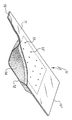
도 1은 본 발명의 마그네슘 분배기의 실시예를 도시하며,1 shows an embodiment of the magnesium distributor of the present invention,
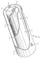
도 2는 본 발명의 마그네슘 분배기의 다른 실시예를 도시하는 일부 절단도이며,2 is a partial cutaway view showing another embodiment of the magnesium distributor of the present invention,
도 3은 본 발명에 따른 용도를 위한 조성물로부터 마그네슘의 증발 특성을 나타내는 그래프이며,3 is a graph showing the evaporation properties of magnesium from a composition for use according to the invention,
도 4는 종래 기술에 따른 조성물로부터 마그네슘의 증발 특성을 나타내는 그래프이며,4 is a graph showing the evaporation characteristics of magnesium from the composition according to the prior art,
도 5는 본 발명에 따른 용도를 위한 하나의 조성물과 종래 기술에 따른 하나의 조성물로부터 두 개의 다른 마그네슘 증발 실험 간의 비교를 나타내는 그래프이다.5 is a graph showing a comparison between two different magnesium evaporation experiments from one composition for use according to the invention and one composition according to the prior art.
본 발명의 발명자들은 43.34 중량% 까지의 마그네슘을 함유하는 마그네슘-구리 조성물이 마그네슘 증발을 필요로 하는 산업상의 이용분야에 특히 적합하다는 것을 발견했는데, 이는 실온에 안정하고, 중요한 양의 가스가 흡수되지 않으며 마그네슘 증발을 제어할 수 있기 때문이다. 또한, 이들은 제조가 쉽고, 양호한 기계적 특성을 가지며, 이들 조성물로부터 금속의 증발을 통해 생성된 마그네슘 증착물(또는 마그네슘을 함유하는 증착물)이 미량의 구리도 포함하지 않는다.The inventors of the present invention have found that magnesium-copper compositions containing up to 43.34% by weight of magnesium are particularly suitable for industrial applications requiring magnesium evaporation, which is stable at room temperature and does not absorb significant amounts of gas. Because it can control magnesium evaporation. In addition, they are easy to manufacture, have good mechanical properties, and the magnesium deposits (or magnesium containing deposits) produced through the evaporation of metals from these compositions do not contain trace amounts of copper.
본 발명의 용도를 위한 조성물은 화합물 Mg2Cu에 대응하는 최대 43.34 중량% 의 마그네슘 함량을 가진다. 마그네슘의 함량이 보다 높은 조성물이 사용될 수 있으나, 이들은 이들 화합물과 금속 마그네슘의 기계적 혼합물으로 형성되며 후자의 성분들은 순수한 마그네슘의 경우에 전술한 바와 같은 단점들을 초래한다.The composition for use of the invention has a magnesium content of up to 43.34% by weight corresponding to compound Mg 2 Cu. Compositions with higher magnesium content can be used, but they are formed from mechanical mixtures of these compounds and metal magnesium and the latter components lead to the disadvantages described above in the case of pure magnesium.
반대로, 본 발명의 용도를 위한 조성물에 있어서 마그네슘의 최소 함량은 긱술적 고려에 의해 엄격하게 제한할 수 없으나, 마그네슘은 산업적으로 유용한 수율과 내구성을 갖는 소자에 대한 증발원을 제공하기 위해 너무 낮지 않은 양으로 존재하는 것이 바람직하다. 바람직하게, 이들 조성물은 마그네슘의 중량%로 적어도 10 %, 바람직하게 적어도 16.06 %를 함유한다. 후자의 마그네슘 함량은 MgCu2에 대응한다.In contrast, the minimum content of magnesium in the composition for use of the present invention cannot be strictly limited by gistological considerations, but the amount of magnesium is not too low to provide an evaporation source for devices with industrially useful yields and durability. It is preferable to exist as. Preferably these compositions contain at least 10%, preferably at least 16.06% by weight of magnesium. The latter magnesium content corresponds to MgCu 2 .
본 발명의 용도를 위한 조성물은 소정의 조성을 갖는 액체를 냉각함으로써 용이하게 준비될 수 있다. 용융물이 정확히 16.05 중량 또는 43.34 중량%의 마그네슘 함량을 가질 때 (예를 들어, 맥그로우힐 출판사, 1958년판 엠. 한센에 의해 편집된 "이원 합금의 조직"으로 공개된)마그네슘-구리 시스템의 상태도로부터 결정되는 바와 같이, 용융물이 고화된 제품은 각각, MgCu2와 Mg2Cu이며, 출발 용융물의 마그네슘 함량이 16.05 중량% 이하인 경우에, 결과적인 고체는 MgCu2와 금속 구리의 기계적 혼합물인 반면에, 출발 용융물의 마그네슘 함량이 각각 16.05 중량%와 43.34 중량%인 경우에, 결과적인 고체는 두 화합물 MgCu2와 Mg2Cu의 기계적 혼합물이다. 결국, 임의의 결과적인 조성물인 단일 또는 이중 성분은 그 성분들의 추가의 분리 단계 또는 정화 단계의 필요 없이 본 발명의 목적에 적합하다.Compositions for use in the present invention can be readily prepared by cooling a liquid having a predetermined composition. From the state diagram of the magnesium-copper system when the melt has a magnesium content of exactly 16.05 wt. As determined, the products in which the melt was solidified were MgCu 2 and Mg 2 Cu, respectively, and when the magnesium content of the starting melt was 16.05% by weight or less, the resulting solid was a mechanical mixture of MgCu 2 and metal copper, If the magnesium content of the starting melt is 16.05% and 43.34% by weight, respectively, the resulting solid is a mechanical mixture of the two compounds MgCu 2 and Mg 2 Cu. In the end, any resulting composition, either a single or dual component, is suitable for the purposes of the present invention without the need for further separation or purification of the components.
상기 용융물의 고화로 얻은 잉곳은 본 발명의 다른 일면인 마그네슘 분배기의 제작을 위한 Mg-Cu 조성물의 용도를 위한 양호한 물리적 형태를 제공하는 분말을 얻기 위해 쉽게 연마될 수 있다.The ingot obtained by solidification of the melt can be easily polished to obtain a powder that provides a good physical form for the use of the Mg-Cu composition for the manufacture of the magnesium distributor, which is another aspect of the present invention.
본 발명의 마그네슘 분배기는 마그네슘 증기를 유출시킬 수 있는 구멍 또는 기공들을 갖는 벽의 적어도 일부분이 노출되며 내측에 소정의 Mg-Cu 조성물이 존재하는 컨테이너로 구성된다.The magnesium distributor of the present invention consists of a container in which at least a portion of a wall having pores or pores capable of releasing magnesium vapor is exposed and a predetermined Mg-Cu composition is present inside.
컨테이너는 적용 분야에 적합한 임의의 재료와 형상으로 제조될 수 있다.The container can be made of any material and shape suitable for the application.
특히, 컨테이너의 재료와 관련하여, 이는 사용 가능한 전체 온도 범위, 일반적으로 실온 내지 약 1000 ℃ 범위에 걸쳐 Mg-Cu 조성물과 작동 분위기에 대해 화학적으로 불활성이어야 한다. 동일한 온도 범위에서, 컨테이너를 형성하는 재료는 물리적으로 실질적으로 변형되어서 (열팽창과는 무관하게)기계적 저항이나 형상이 변형되어서는 않되며 작동 중에 가능한 한 적은 양의 가스를 방출할 수 있어야 한다. 그러한 특징들이 제공된 재료는 예를 들어, 금속 또는 금속 합금, 몇몇 세라믹 또는 흑연이다. 금속의 용도는 용이한 가공 및 성형 능력으로 인해 양호하다. 이들 재료의 사용에 있어서의 다른 장점은 분배기가 단지 컨테이너 벽 내에 전류를 흐르게 하거나 무선 주파수를 통해 유도함으로써 마그네슘의 증발 온도로 가용될 수 있다는 점이다. 또한, 대응하는 형상의 금속 히터 내에 삽입되는 세라믹 재료의 도가니를 포함하여 두 부품 사이에 밀폐 접촉을 보장하는 복합 컨테이너를 사용하는 것도 가능하다. 컨테이너를 구현하기 위한 바람직한 금속 및 합금은 몰리브덴, 탄탈, 텅스텐, 니켈, 스틸 및 니켈-크롬 합금이다In particular, with regard to the material of the container, it should be chemically inert to the Mg-Cu composition and the operating atmosphere over the entire usable temperature range, generally from room temperature to about 1000 ° C. In the same temperature range, the material forming the container must be physically substantially deformed (regardless of thermal expansion) so that no mechanical resistance or shape is deformed and it is possible to release as little gas as possible during operation. The material provided with such features is, for example, a metal or metal alloy, some ceramics or graphite. The use of metal is good due to its easy processing and forming ability. Another advantage in the use of these materials is that the distributor can be made available at the evaporation temperature of magnesium by only flowing current in the container wall or directing it via radio frequency. It is also possible to use a composite container which ensures a hermetic contact between the two parts, including a crucible of ceramic material inserted into a metal heater of a corresponding shape. Preferred metals and alloys for implementing the container are molybdenum, tantalum, tungsten, nickel, steel and nickel-chromium alloys.
컨테이너의 형상은 US 3,578,834, US 3,579,459, US 3,598,384, US 3,636,302, US 3,663,121, 및 US 4,233,936호 또는 특허 출원 WO 02/093664호로부터 공지된 어는 것일 수 있다. 다양한 형상과 재료의 컨테이너도 예를 들어, 오스트리아 레떼 소재의 오스트리안 컴파니 플란제 에스이, 미국 일리노이스 윌로우블룩 소재의 유에스 이들웨스트 텅스텐 서비스, 또는 미국 캘리포니아 롱 비치 소재의 알.디. 매티스 컴파니로부터 상업적으로 이용가능하다. The shape of the container may be one known from US 3,578,834, US 3,579,459, US 3,598,384, US 3,636,302, US 3,663,121, and US 4,233,936 or patent application WO 02/093664. Containers of various shapes and materials are also described, for example, Austrian Company Flanze S., Rete, Austria, US Idle West Tungsten Service in Willowbrook, Illinois, or Al.D., Long Beach, CA. Commercially available from Mathis Company.
본 발명에 따른 양호한 형상의 분배기가 도 1에 도시되어 있다. 분배기(10)는 콘테이너로 구성되는데, 그 내측에는 본 발명의 조성물이 위치된다. 콘테이너는 상부(11)와 하부(12)를 접합함으로써 형성된다. 상기 두 개의 부분은 바람직하게 금속으로 이루어지며 예를 들어, 점(spot) 용접에 의해 서로 접합된다. 상기 하부에는 (예를 들어, 냉간 압연에 의해 얻어지는)중앙 영역 내에 공동이 제공되며, 공동의 내측에는 본 발명의 조성물이 수용되는 반면에, 상기 상부에는 마그네슘 증기의 유출을 위한 복수의 개구(13,13', ...)가 제공되어 있다. 도면에 있어서, 점선에 의해 한정된 직사각형 영역은 하부(12)의 공동 부분에 대응한다. 본 발명의 조성물(혼합물)은 도면에 도시한 바와 같이 분말 형태로 하부의 공동에 제공되며, 본 발명의 조성물은 도면 부호 14로 도시되어 있다. 이와는 달리, 분말 원료를 알약의 형태로 형성하거나 분말 원료료 공동을 채우는 것도 가능하다. 분배기(10)에는 특히, 직류 전류에 의해 분배기를 가열하기 위한 전력 터미널에 연결되도록 채용되는 두 개의 연장 단부(15,15')가 제공된다. A distributor of good shape according to the invention is shown in FIG. 1. The
특히, 분배기가 대량 금속을 방출하는 것이 바람직할 때 사용되는 마그네슘 분배기의 다른 양호한 실시예가 본 출원인에 의해 출원된 WO 2006/057021호에 설명되어 있다. 이러한 분배기가 도 2에 일부 절단도로 도시되어 있으며, 원통형 형상을 갖는 동축의 컨테이너와 차폐물로 형성되어 있다. 분배기(20)는 컨테이너(21)와 차폐물(22)로 구성된다. 컨테이너(21)에는 구멍(23)이 제공되어 있다(도면의 분배기는 3 개의 구멍을 가지는데, 그 중 하나는 차폐물(22)에 의해 가려져 있으나, 컨테이너에는 하나, 둘, 또는 3 개 이상의 구멍이 제공될 수 있다). 차폐물(22)에는 컨테이너 상의 구멍(23)에 대응하는 구멍(24)들이(단지 하나만 도시됨) 제공된다. 도면에 있어서, 구멍(23,24)은 원형 형상을 갖는 것으로 도시되어 있으나, 구멍들은 예를 들어, 긴 형태의 슬릿과 같은 다른 형상들도 가질 수 있다. 컨테이너의 내측에는 가루분 형태로 도시된 마그네슘-구리 조성물(25)이 제공된다(그러나, 알약 형태일 수도 있다). 컨테이너(21)는 주 원통형 벽에 용접될 수 있는 측벽(26)에 의해 단부가 폐쇄되거나, 원통형 벽 내에 삽입되는 "캡"의 형태일 수 있다. 이들 측벽(26) 상에는 일반적으로, 전력 공급 터미널(도시 않음)에 연결하기 위한 소자(27)가 제공된다(도면에는 벽 상의 단순한 돌기로서 도시되어 있음). 컨테이너(21)와 차폐물(22)은 시스템의 단부에 대해 일반적으로 세라믹으로 제조되며 서로로부터 120°로 축대칭으로 배열되는 예를 들어, 3 개의 열 절연 스페이서(28)에 의해 소정의 거리로 이격되어 있다(도 2에는 단지 하나만이 도시되어 있음). 마지막으로, 차폐물은 컨테이너, 소자(27) 또는 전기 전기 단자(feed through:도시 않음)와 접촉하지는 않지만 이들에 가능한 한 가깝게 있는 측벽(도면에 도시 않음)을 갖거나 측벽에 교대로 연결될 수 있으며, 이들 측벽들은 분배기 측면으로부터 마그네슘 증기의 누출을 방지할 목적을 갖는 동시에, 잠재적인 열팽창시 내측 컨테이너나 전기 전기 단자 부품들의 자유로운 상호 운동을 가능하게 하도록 상기 부품들과 접촉(및 고정)되어서는 않된다.In particular, another preferred embodiment of a magnesium distributor used when it is desired for the distributor to release large amounts of metal is described in WO 2006/057021 filed by the applicant. Such a dispenser is shown in partial cutaway in FIG. 2 and is formed of a coaxial container and shield having a cylindrical shape. The
가루분말 또는 알약 형태로 사용되는 Mg-Cu 조성물의 분말은 일반적으로, 1 mm 미만, 바람직하게 500 ㎛ 미만의 입도를 가진다. 더욱 바람직한 입도는 약 10 내지 128 ㎛ 범위이다. 10 ㎛ 미만의 입도를 갖는 분말은 일반적으로 제조 중의 처리와 분배기 내의 유지가 어렵다.The powder of the Mg-Cu composition used in the form of powder powder or pills generally has a particle size of less than 1 mm, preferably less than 500 μm. More preferred particle sizes range from about 10 to 128 μm. Powders having a particle size of less than 10 μm are generally difficult to process during manufacture and to maintain in the dispenser.
본 발명은 다음의 예들에 의해 더욱 상세히 설명된다.The invention is illustrated in more detail by the following examples.
예 1Example 1
본 발명에 따른 조성물은 19.8 그램의 마그네슘 조각과 30.2 그램의 구리 분말로 구성되는 혼합물을 알루미나 도가니에 유입시키며, 600 hPa의 아르곤 분위기 하에서 도가니를 유도 오븐의 내측에 넣으며, 혼합물이 용융될 때까지 오븐을 가열하며(그 결과로 오븐의 창을 통해 용융물이 관찰됨), 용융 온도에서 5분 동안 오븐을 유지하며, 용융물을 실온으로 냉각시키며, 최종적으로 얻어진 잉곳을 압착형 밀로 연마함으로써 준비된다. 이렇게 얻어진 분말은 체가름하여 128 ㎛ 미만의 입도를 갖는 분말을 얻었다. 이러한 분말의 마그네슘 함량은 39.6 중량%이다. 이중 15.8 그램의 분말이 외경 28.4 mm, 길이 10 ㎝ 및 두 개의 원형 구멍(도 2의 구멍(23))을 갖는 컨테이너와 내경 36 mm와 길이 10 ㎝의 차폐물로 구성되는 도 2에 도시한 형태의 분배기 내측으로 도입되었다. 컨테이너와 차폐물은 AISI 304 L 스 틸로 제조된다. 그렇게 배열된 분배기가 진공 실험 챔버 내측에 놓이며, 실험 챔버에는 (컨테이너(21) 상에 위치된 도 2의 도면부호 27과 같은 접점에 의해)분배기의 전기 공급원을 위한 전기 단자 및 진공 시스템에의 연결을 위한 하나의 구멍이 제공되어 있다. 실험 챔버의 내측에는 마그네슘 분배기 위에 36 ㎝의 거리에 위치되는 샘플 캐리어도 제공되며, 샘플 캐리어의 근처에는 상부에 증착된 재료의 중량에 따른 재료 결정의 진동 주파수의 편차를 활용함으로써 얇은 필름의 성장률을 측정하기 위해 본 기술 분야에 사용되는, 공지된 대로의 석영 결정 미량 측정기(QCM)가 제공된다. QCM은 마그네슘의 소정의 증착률에 따라 시스템으로 공급되는 전류와 그에 따른 온도를 자동으로 조정하도록 컴퓨터를 경유하여 분배기의 전력 공급 시스템에 연결된다.The composition according to the invention introduces a mixture consisting of 19.8 grams of magnesium pieces and 30.2 grams of copper powder into an alumina crucible, placing the crucible inside an induction oven under an argon atmosphere of 600 hPa, until the mixture melts. Is prepared by heating the furnace (as a result of which the melt is observed through the window of the oven), holding the oven for 5 minutes at the melting temperature, cooling the melt to room temperature and polishing the finally obtained ingot with a compacting mill. The powder thus obtained was sieved to obtain a powder having a particle size of less than 128 μm. The magnesium content of this powder is 39.6% by weight. Of these, 15.8 grams of powder consist of a container having an outer diameter of 28.4 mm, a length of 10 cm and two circular holes (
샘플 캐리어 상에는 약 30 ㎠의 표면을 갖는 정방형 석영 유리가 고정되며, 석영 유리의 한 면이 분배기의 바로 위에 이를 유리에 접합시키는 방향에 수직이 되도록 지향된다. 실험 챔버는 배기되며 압력이 10-6 hPa의 값에 도달할 때 마그네슘 증발 실험이 전류 흐름을 통한 컨테이너를 가열하고 초 당 0.3 Å(Å/초)의 마그네슘 증착물의 성장률을 갖도록 전력 공급 시스템을 제어하기 위해 컴퓨터를 세팅하는 것으로 출발한다. 이러한 실험은 25 시간 후에 완료된다.A square quartz glass having a surface of about 30
이러한 실험의 결과가 도 3에 도시되어 있다. 특히, 곡선(DR1)은 Å/초 단위로 측정된 마그네슘 증착물의 성장률(그 값은 도면의 좌측에 있는 수직축 상에 설정되어 있음)에 관한 것인 반면에, 곡선(C1)은 암페어 단위로 측정된 실험 중의 전류 값 동향(그 값은 도면의 우측에 있는 수직축 상에 설정되어 있음)에 관한 것이다.The results of this experiment are shown in FIG. 3. In particular, curve DR1 relates to the rate of growth of the magnesium deposit measured in milliseconds per second (its value is set on the vertical axis on the left side of the figure), while curve C1 is measured in amperes. Current value trends during the experiments (the values are set on the vertical axis on the right side of the figure).
실험의 말기에서, 유리 상에 형성된 증착물은 마그네슘의 존재만을 나타내는 ICP를 통한 화학적 분석이 이루어진다.At the end of the experiment, deposits formed on the glass are subjected to chemical analysis via ICP indicating only the presence of magnesium.
예 2(비교예)Example 2 (comparative)
예 1의 실험이 반복되나, 본 예에서는 41.3 그램의 마그네슘 조각과 32.4 그램의 알루미늄 분말로 이루어진 혼합물을 용융하고, 연마 후에는 56.04 중량%의 마그네슘과 43.96 중량%의 조성을 갖는 분말이 얻어졌다. 분배기에는 이러한 분말 9.06 그램이 충전되었다.The experiment of Example 1 was repeated, but in this example a mixture consisting of 41.3 grams of magnesium pieces and 32.4 grams of aluminum powder was melted and after polishing a powder having a composition of 56.04 wt% magnesium and 43.96 wt% was obtained. The dispenser was filled with 9.06 grams of this powder.
이러한 분배기는 예 1에 사용된 챔버 내측에 놓여졌으며, 동일한 실험이 수행되었으나, 이 경우에는 증착물의 성장률에 의해 제어되는 피이드백 전류에 기초한 실험의 전체적인 자동 제어가 불가능했는데, 그 이유는 성장률의 불연속성과 빈번한 점프 때문이다. 따라서, 증발 실험은 공급 전류를 수동 조절함으로써 수행되었다. 또한 이 경우에 실험은 25 시간 후에 종료되었다. 증발 실험의 결과는 도 4에 도시되어 있다. 곡선(DR2)은 마그네슘의 증착률을 나타내는 반면에, 곡선(C2)은 실험 중의 전류 동향을 나타낸다.This distributor was placed inside the chamber used in Example 1, and the same experiment was performed, but in this case the overall automatic control of the experiment based on the feedback current controlled by the growth rate of the deposit was not possible, because of the discontinuity of the growth rate. And frequent jumps. Therefore, the evaporation experiment was performed by manually adjusting the supply current. Also in this case the experiment was terminated after 25 hours. The results of the evaporation experiment are shown in FIG. 4. Curve DR2 represents the deposition rate of magnesium, while curve C2 represents the current trend during the experiment.
실험의 말기에서 유리 상에 형성된 증착물은 마그네슘 증착물이 0.2 중량%의 알루미늄을 함유함을 나타내는 ICP를 통한 화학적 분석이 이루어졌다.At the end of the experiment, the deposits formed on the glass were subjected to chemical analysis via ICP indicating that the magnesium deposits contained 0.2% by weight of aluminum.
예 3Example 3
다른 마그네슘 증발 실험이 본 발명의 용도를 위한 조성물로부터 수행되었다. 이 경우에, 예 1에서 사용된, Mg-Cu 조성과 동일한 분말을 9 그램 함유하는, 붕소 질화물로 제조된 상부 개방형 도가니가 사용되었다(C5 일련 번호의 도가니가 디.알 매티스 컴파니(D.R. Mathis Company)의 CH12 시리즈의 히터 내측에 놓여졌다). 실험은 실험 1과 동일한 챔버에서 수행되었다. 마그네슘의 증발률은 곡선(DR3)으로서 도 5에 도시되었다(곡선(C3)은 실험 중의 전류의 동향을 나타낸다).Another magnesium evaporation experiment was performed from the composition for use of the present invention. In this case, a top open crucible made of boron nitride containing 9 grams of the same powder as the Mg-Cu composition used in Example 1 was used (a crucible of C5 serial number was D. Al Mathis Company (DR Mathis). Inside the heater of the CH12 series of the company). The experiment was performed in the same chamber as
예 4Example 4
예 3의 실험이 반복되었지만, 예 2에 사용된 것과 동일한 Mg-Al 조성의 분말 9 그램이 사용되었다. 마그네슘의 증발 실험은 곡선(DR4)로서 도 5에 도시되어 있다(곡선(C4)는 실험 중의 전류 동향을 나타낸다). 또한 이 경우에, 증착물의 성장률에 의해 제어되는 피이드백 전류에 기초하여 실험을 전체적으로 자동 제어하는 불가능한데, 그 이유는 성장률의 불연속성과 빈번한 점프 때문이며, 증발 실험은 공급 전류의 수동 제어에 의해 수행되었으며, 30 시간 후에 종료되었다.Although the experiment of Example 3 was repeated, 9 grams of powder of the same Mg-Al composition as that used in Example 2 was used. The evaporation experiment of magnesium is shown in FIG. 5 as curve DR4 (curve C4 represents the current trend during the experiment). Also in this case, it is impossible to automatically control the experiment as a whole based on the feedback current controlled by the growth rate of the deposit, because of the discontinuity of the growth rate and frequent jumps, and the evaporation experiment was performed by manual control of the supply current. It ended after 30 hours.
실험 결과에 대한 논의Discuss Experiment Results
도 3의 DR1과 도 5의 DR3에 의해 나타낸 바와 같이, 일정한 작동 상태에 도달하기 위해 시스템에 의해 요구되는 약 1 시간의 초기 과도 상태 이후에, 마그네슘-구리 조성물은 증발률이 일정한 비율로 제어될 수 있어서, 마그네슘 증착물의 일정한 성장률에 의한 증발을 자동으로 제어할 수 있게 했다. 또한, 예 1은 결과적인 마그네슘 증착물이 불순물을 갖지 않는 것으로 나타났다. 역으로, 도 4의 곡선(DR2)과 도 5의 곡선(DR4)은 종래 기술의 마그네슘-알루미늄 조성의 경우에 증발 특성이 덜 제어됨으로써, 금속 증착물의 예정된 성장률에 따른 공정의 자동화가 불가능하다. 예 2도 동일한 증착물이 미량의 알루미늄을 함유하는 덜 순수한 것으로 나타났다.As shown by DR1 of FIG. 3 and DR3 of FIG. 5, after about an hour of initial transient state required by the system to reach a constant operating state, the magnesium-copper composition may be controlled at a constant rate of evaporation. It was possible to automatically control evaporation due to a constant growth rate of magnesium deposits. In addition, Example 1 showed that the resulting magnesium deposit was free of impurities. Conversely, the curve DR2 of FIG. 4 and the curve DR4 of FIG. 5 have less controlled evaporation properties in the case of the magnesium-aluminum composition of the prior art, thereby making it impossible to automate the process according to the predetermined growth rate of the metal deposit. Example 2 also showed that the same deposits were less pure, containing trace amounts of aluminum.
Claims (14)
Applications Claiming Priority (3)
| Application Number | Priority Date | Filing Date | Title |
|---|---|---|---|
| IT000444A ITMI20060444A1 (en) | 2006-03-13 | 2006-03-13 | USE OF MAGNESIUM-COPPER COMPOSITIONS FOR MAGNESIUM EVAPORATION AND MAGNESIUM DISPENSERS |
| ITMI2006A000444 | 2006-03-13 | ||
| PCT/IT2007/000181 WO2007105252A1 (en) | 2006-03-13 | 2007-03-12 | Use of magnesium-copper compositions for the evaporation of magnesium and magnesium dispensers |
Publications (2)
| Publication Number | Publication Date |
|---|---|
| KR20080102425A true KR20080102425A (en) | 2008-11-25 |
| KR101382538B1 KR101382538B1 (en) | 2014-04-07 |
Family
ID=39877970
Family Applications (1)
| Application Number | Title | Priority Date | Filing Date |
|---|---|---|---|
| KR1020087024640A Active KR101382538B1 (en) | 2006-03-13 | 2007-03-12 | Using method of magnesium-copper compositions for the evaporation of magnesium and magnesium dispensers |
Country Status (11)
| Country | Link |
|---|---|
| US (1) | US8029597B2 (en) |
| EP (1) | EP1996743B1 (en) |
| JP (1) | JP5118689B2 (en) |
| KR (1) | KR101382538B1 (en) |
| CN (1) | CN101448970B (en) |
| AT (1) | ATE467697T1 (en) |
| DE (1) | DE602007006443D1 (en) |
| ES (1) | ES2343337T3 (en) |
| IT (1) | ITMI20060444A1 (en) |
| TW (1) | TWI397594B (en) |
| WO (1) | WO2007105252A1 (en) |
Families Citing this family (2)
| Publication number | Priority date | Publication date | Assignee | Title |
|---|---|---|---|---|
| ITMI20112051A1 (en) * | 2011-11-11 | 2013-05-12 | Getters Spa | ORGANIC-INORGANIC COMPOSITION FOR THE RELEASE IN STEAM PHASE OF ALKALINE AND ALKALINE-TERRAIN METALS |
| KR102056100B1 (en) * | 2016-04-01 | 2019-12-17 | 주식회사 엘지화학 | 3D Printing Method |
Family Cites Families (18)
| Publication number | Priority date | Publication date | Assignee | Title |
|---|---|---|---|---|
| US3579459A (en) * | 1966-12-13 | 1971-05-18 | Getters Spa | Metal vapor generating compositions |
| DE1945508B2 (en) * | 1968-09-13 | 1971-06-09 | DEVICE FOR RELEASING METAL DAMPERS | |
| GB1274528A (en) * | 1968-09-13 | 1972-05-17 | Getters Spa | Improvements in or relating to metal vapour generators |
| US3663121A (en) * | 1969-05-24 | 1972-05-16 | Getters Spa | Generation of metal vapors |
| US4233936A (en) * | 1979-05-08 | 1980-11-18 | Rca Corporation | Alkali metal dispenser |
| FR2611746B1 (en) * | 1987-03-06 | 1989-06-30 | Centre Nat Etd Spatiales | DEVICE FOR VACUUM EVAPORATION OF A CONTINUOUS METAL |
| JPH03170661A (en) * | 1989-11-27 | 1991-07-24 | Kobe Steel Ltd | Method for evaporating sublimable metal |
| JPH08269696A (en) * | 1995-03-28 | 1996-10-15 | Nisshin Steel Co Ltd | Method for vaporizing mg |
| JPH08283942A (en) * | 1995-04-14 | 1996-10-29 | Ishikawajima Harima Heavy Ind Co Ltd | Evaporation method for sublimable metal materials |
| CN1108730C (en) * | 1996-09-04 | 2003-05-14 | 剑桥显示技术有限公司 | Organic light-emitting device with improved cathode |
| JPH10270171A (en) * | 1997-01-27 | 1998-10-09 | Junji Kido | Organic electroluminescent device |
| ITMI20010995A1 (en) | 2001-05-15 | 2002-11-15 | Getters Spa | CESIUM DISPENSERS AND PROCESS FOR THEIR USE |
| US6770502B2 (en) * | 2002-04-04 | 2004-08-03 | Eastman Kodak Company | Method of manufacturing a top-emitting OLED display device with desiccant structures |
| EP1422281A1 (en) * | 2002-11-19 | 2004-05-26 | Ciba SC Holding AG | Organic electroluminescent element |
| JP4400570B2 (en) * | 2003-10-02 | 2010-01-20 | 株式会社豊田自動織機 | Electroluminescent device |
| US7790890B2 (en) * | 2004-03-31 | 2010-09-07 | Konica Minolta Holdings, Inc. | Organic electroluminescence element material, organic electroluminescence element, display device and illumination device |
| NL1026214C2 (en) * | 2004-05-18 | 2005-11-21 | Otb Group Bv | Method and device for applying an active substance to a substrate. |
| ITMI20042279A1 (en) * | 2004-11-24 | 2005-02-24 | Getters Spa | ALKALINE METAL DISPENSER SYSTEM ABLE TO DELIVER HIGH QUANTITIES OF METALS |
-
2006
- 2006-03-13 IT IT000444A patent/ITMI20060444A1/en unknown
-
2007
- 2007-03-09 TW TW096108274A patent/TWI397594B/en active
- 2007-03-12 KR KR1020087024640A patent/KR101382538B1/en active Active
- 2007-03-12 DE DE602007006443T patent/DE602007006443D1/en active Active
- 2007-03-12 US US12/282,758 patent/US8029597B2/en active Active
- 2007-03-12 AT AT07736686T patent/ATE467697T1/en active
- 2007-03-12 JP JP2009500007A patent/JP5118689B2/en active Active
- 2007-03-12 EP EP07736686A patent/EP1996743B1/en active Active
- 2007-03-12 WO PCT/IT2007/000181 patent/WO2007105252A1/en not_active Ceased
- 2007-03-12 ES ES07736686T patent/ES2343337T3/en active Active
- 2007-03-12 CN CN2007800088701A patent/CN101448970B/en active Active
Also Published As
| Publication number | Publication date |
|---|---|
| DE602007006443D1 (en) | 2010-06-24 |
| CN101448970A (en) | 2009-06-03 |
| ATE467697T1 (en) | 2010-05-15 |
| US8029597B2 (en) | 2011-10-04 |
| TWI397594B (en) | 2013-06-01 |
| EP1996743A1 (en) | 2008-12-03 |
| JP2009530491A (en) | 2009-08-27 |
| US20090266201A1 (en) | 2009-10-29 |
| TW200745358A (en) | 2007-12-16 |
| WO2007105252A1 (en) | 2007-09-20 |
| ITMI20060444A1 (en) | 2007-09-14 |
| JP5118689B2 (en) | 2013-01-16 |
| WO2007105252A8 (en) | 2008-10-16 |
| EP1996743B1 (en) | 2010-05-12 |
| ES2343337T3 (en) | 2010-07-28 |
| CN101448970B (en) | 2011-03-09 |
| KR101382538B1 (en) | 2014-04-07 |
Similar Documents
| Publication | Publication Date | Title |
|---|---|---|
| KR100742424B1 (en) | How to use cesium dispenser and cesium dispenser | |
| US7794630B2 (en) | Lithium dispenser for lithium evaporation | |
| HU215489B (en) | A combination of materials for mercury-dispensing devices, mercury-dispensing device, and process for introducing mercury inside electron tubes | |
| HU215491B (en) | Combination of materials for mercury-dispensing devices, mercury-dispensing devices and process for the introduction of mercury inside electron tubes | |
| KR20020059353A (en) | Epitaxial growing method for growing aluminum nitride and growing chamber therefor | |
| EP0401387B1 (en) | Process for producing single crystal | |
| JP3929397B2 (en) | Method and apparatus for manufacturing organic EL element | |
| KR101382538B1 (en) | Using method of magnesium-copper compositions for the evaporation of magnesium and magnesium dispensers | |
| EP1817787B1 (en) | Dispensing system for alkali metals capable of releasing a high quantity of metals | |
| EP2325348B1 (en) | Device and method for thermal evaporation of silicon | |
| US5312506A (en) | Method for growing single crystals from melt | |
| JP3817054B2 (en) | Vapor source crucible and vapor deposition apparatus | |
| US3499785A (en) | Coating substrates by evaporation-deposition | |
| HK1133284A (en) | Use of magnesium-copper compositions for the evaporation of magnesium and magnesium dispensers | |
| EP2824071B1 (en) | Silicon refining device | |
| EP0321576A1 (en) | Method for growing single crystal from molten liquid | |
| HK1068495B (en) | Cesium dispensers and process for the use thereof | |
| JPS5812699B2 (en) | High temperature metal ion source device | |
| Mikula et al. | Thermodynamic investigations of ternary liquid alloys | |
| JPH0734176A (en) | Silicon-germanium alloy containing high concentration of phosphorus and its production | |
| JP2002097568A (en) | Vapor deposition method of metal thin film |
Legal Events
| Date | Code | Title | Description |
|---|---|---|---|
| E13-X000 | Pre-grant limitation requested |
St.27 status event code: A-2-3-E10-E13-lim-X000 |
|
| PA0105 | International application |
St.27 status event code: A-0-1-A10-A15-nap-PA0105 |
|
| P11-X000 | Amendment of application requested |
St.27 status event code: A-2-2-P10-P11-nap-X000 |
|
| P18-X000 | Priority claim added or amended |
St.27 status event code: A-2-2-P10-P18-nap-X000 |
|
| PG1501 | Laying open of application |
St.27 status event code: A-1-1-Q10-Q12-nap-PG1501 |
|
| A201 | Request for examination | ||
| P11-X000 | Amendment of application requested |
St.27 status event code: A-2-2-P10-P11-nap-X000 |
|
| P13-X000 | Application amended |
St.27 status event code: A-2-2-P10-P13-nap-X000 |
|
| PA0201 | Request for examination |
St.27 status event code: A-1-2-D10-D11-exm-PA0201 |
|
| R17-X000 | Change to representative recorded |
St.27 status event code: A-3-3-R10-R17-oth-X000 |
|
| E902 | Notification of reason for refusal | ||
| PE0902 | Notice of grounds for rejection |
St.27 status event code: A-1-2-D10-D21-exm-PE0902 |
|
| E13-X000 | Pre-grant limitation requested |
St.27 status event code: A-2-3-E10-E13-lim-X000 |
|
| P11-X000 | Amendment of application requested |
St.27 status event code: A-2-2-P10-P11-nap-X000 |
|
| P13-X000 | Application amended |
St.27 status event code: A-2-2-P10-P13-nap-X000 |
|
| E701 | Decision to grant or registration of patent right | ||
| PE0701 | Decision of registration |
St.27 status event code: A-1-2-D10-D22-exm-PE0701 |
|
| GRNT | Written decision to grant | ||
| PR0701 | Registration of establishment |
St.27 status event code: A-2-4-F10-F11-exm-PR0701 |
|
| PR1002 | Payment of registration fee |
St.27 status event code: A-2-2-U10-U12-oth-PR1002 Fee payment year number: 1 |
|
| PG1601 | Publication of registration |
St.27 status event code: A-4-4-Q10-Q13-nap-PG1601 |
|
| FPAY | Annual fee payment |
Payment date: 20170323 Year of fee payment: 4 |
|
| PR1001 | Payment of annual fee |
St.27 status event code: A-4-4-U10-U11-oth-PR1001 Fee payment year number: 4 |
|
| FPAY | Annual fee payment |
Payment date: 20180327 Year of fee payment: 5 |
|
| PR1001 | Payment of annual fee |
St.27 status event code: A-4-4-U10-U11-oth-PR1001 Fee payment year number: 5 |
|
| FPAY | Annual fee payment |
Payment date: 20190322 Year of fee payment: 6 |
|
| PR1001 | Payment of annual fee |
St.27 status event code: A-4-4-U10-U11-oth-PR1001 Fee payment year number: 6 |
|
| PR1001 | Payment of annual fee |
St.27 status event code: A-4-4-U10-U11-oth-PR1001 Fee payment year number: 7 |
|
| PR1001 | Payment of annual fee |
St.27 status event code: A-4-4-U10-U11-oth-PR1001 Fee payment year number: 8 |
|
| PR1001 | Payment of annual fee |
St.27 status event code: A-4-4-U10-U11-oth-PR1001 Fee payment year number: 9 |
|
| PR1001 | Payment of annual fee |
St.27 status event code: A-4-4-U10-U11-oth-PR1001 Fee payment year number: 10 |
|
| PR1001 | Payment of annual fee |
St.27 status event code: A-4-4-U10-U11-oth-PR1001 Fee payment year number: 11 |
|
| R18-X000 | Changes to party contact information recorded |
St.27 status event code: A-5-5-R10-R18-oth-X000 |
|
| PR1001 | Payment of annual fee |
St.27 status event code: A-4-4-U10-U11-oth-PR1001 Fee payment year number: 12 |
|
| U11 | Full renewal or maintenance fee paid |
Free format text: ST27 STATUS EVENT CODE: A-4-4-U10-U11-OTH-PR1001 (AS PROVIDED BY THE NATIONAL OFFICE) Year of fee payment: 12 |