KR20140051054A - 능동 션트 전류계 장치 및 방법 - Google Patents
능동 션트 전류계 장치 및 방법 Download PDFInfo
- Publication number
- KR20140051054A KR20140051054A KR1020130110520A KR20130110520A KR20140051054A KR 20140051054 A KR20140051054 A KR 20140051054A KR 1020130110520 A KR1020130110520 A KR 1020130110520A KR 20130110520 A KR20130110520 A KR 20130110520A KR 20140051054 A KR20140051054 A KR 20140051054A
- Authority
- KR
- South Korea
- Prior art keywords
- amplifier
- gain
- frequency
- feedback element
- input
- Prior art date
- Legal status (The legal status is an assumption and is not a legal conclusion. Google has not performed a legal analysis and makes no representation as to the accuracy of the status listed.)
- Withdrawn
Links
Images


Classifications
-
- G—PHYSICS
- G01—MEASURING; TESTING
- G01R—MEASURING ELECTRIC VARIABLES; MEASURING MAGNETIC VARIABLES
- G01R19/00—Arrangements for measuring currents or voltages or for indicating presence or sign thereof
-
- G—PHYSICS
- G01—MEASURING; TESTING
- G01R—MEASURING ELECTRIC VARIABLES; MEASURING MAGNETIC VARIABLES
- G01R1/00—Details of instruments or arrangements of the types included in groups G01R5/00 - G01R13/00 and G01R31/00
- G01R1/20—Modifications of basic electric elements for use in electric measuring instruments; Structural combinations of such elements with such instruments
- G01R1/203—Resistors used for electric measuring, e.g. decade resistors standards, resistors for comparators, series resistors, shunts
-
- H—ELECTRICITY
- H03—ELECTRONIC CIRCUITRY
- H03F—AMPLIFIERS
- H03F3/00—Amplifiers with only discharge tubes or only semiconductor devices as amplifying elements
- H03F3/45—Differential amplifiers
- H03F3/45071—Differential amplifiers with semiconductor devices only
- H03F3/45076—Differential amplifiers with semiconductor devices only characterised by the way of implementation of the active amplifying circuit in the differential amplifier
- H03F3/45475—Differential amplifiers with semiconductor devices only characterised by the way of implementation of the active amplifying circuit in the differential amplifier using IC blocks as the active amplifying circuit
-
- G—PHYSICS
- G01—MEASURING; TESTING
- G01R—MEASURING ELECTRIC VARIABLES; MEASURING MAGNETIC VARIABLES
- G01R19/00—Arrangements for measuring currents or voltages or for indicating presence or sign thereof
- G01R19/0023—Measuring currents or voltages from sources with high internal resistance by means of measuring circuits with high input impedance, e.g. OP-amplifiers
-
- G—PHYSICS
- G01—MEASURING; TESTING
- G01R—MEASURING ELECTRIC VARIABLES; MEASURING MAGNETIC VARIABLES
- G01R19/00—Arrangements for measuring currents or voltages or for indicating presence or sign thereof
- G01R19/0092—Measuring current only
-
- H—ELECTRICITY
- H03—ELECTRONIC CIRCUITRY
- H03F—AMPLIFIERS
- H03F1/00—Details of amplifiers with only discharge tubes, only semiconductor devices or only unspecified devices as amplifying elements
- H03F1/34—Negative-feedback-circuit arrangements with or without positive feedback
-
- H—ELECTRICITY
- H03—ELECTRONIC CIRCUITRY
- H03F—AMPLIFIERS
- H03F2200/00—Indexing scheme relating to amplifiers
- H03F2200/261—Amplifier which being suitable for instrumentation applications
-
- H—ELECTRICITY
- H03—ELECTRONIC CIRCUITRY
- H03F—AMPLIFIERS
- H03F2203/00—Indexing scheme relating to amplifiers with only discharge tubes or only semiconductor devices as amplifying elements covered by H03F3/00
- H03F2203/45—Indexing scheme relating to differential amplifiers
- H03F2203/45138—Two or more differential amplifiers in IC-block form are combined, e.g. measuring amplifiers
Landscapes
- Physics & Mathematics (AREA)
- General Physics & Mathematics (AREA)
- Engineering & Computer Science (AREA)
- Power Engineering (AREA)
- Amplifiers (AREA)
- Measurement Of Current Or Voltage (AREA)
- Measurement Of Resistance Or Impedance (AREA)
Abstract
Description
도 1b 는 입력 회로를 저항 RS를 통하여 풀링하기 이ㅜ해 고이득 연산 증폭기를 이용하여 구성된 피드백 전류계의 기본적인 도면이다;
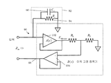
도 2a 는 병렬 RC 피드백 소자 양단의 제어된 음의 이득을 사용하는 능동 션트 전류계 디자인이다;
도 2b 는 도 2a 에 있는 능동 션트 전류계의 이득 고정 증폭기의 이득 B(s)를 도시하는 그래프이다;
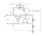
도 3 은 반전 이득이 저항비에 의하여 설정되는 반전 스테이지를 사용하여 구성된 이득 고정 증폭기를 가지는 능동 션트 전류계 디자인이다;
도 4 는 이득이 두 개의 연산 증폭기들 사이에서 분할되는 이득 고정 증폭기를 가지는 능동 션트 전류계 디자인이다;
도 5 는 션트 양단의 전압이 버퍼링되며 저항비에 의하여 다소 감쇠하는 이득 고정 증폭기를 가지는 능동 션트 전류계 디자인이다; 그리고
도 6 은 입력 연산 증폭기가 자신의 피드백 경로에 배치된 작은 이득을 가지는 이득 고정 증폭기를 가지는 능동 션트 전류계 디자인이다.
Claims (18)
- 피시험 디바이스(device under test; DUT)를 통해 흐르는 전류를 측정하기 위한 능동 션트 전류계에 있어서:
주파수 대역 내의 주파수를 가지며 상기 DUT를 통해 흐르는 전류를 나타내는 입력 신호를 수신하도록 구성되는 입력;
상기 DUT를 통해 흐르는 전류를 나타내는 출력 전압을 생성하도록 구성되는 출력;
이득 회로로서, 상기 주파수 대역 내의 주파수에 대하여 변동하는 이득 특성을 가지는 증폭기 및 상기 이득 회로의 출력으로부터 상기 이득 회로의 음의 입력으로 커플링된 임피던스를 가지는 피드백 소자를 가지는, 이득 회로를 포함하고,
피드백 소자 임피던스는 상기 주파수 대역에 걸쳐 상기 피드백 소자 임피던스를 상기 증폭기 이득으로 나눈 값이 최소 주파수 의존성을 가지도록, 증폭기 이득 특성과 상관되게 주파수에 따라 변화하도록 구성되는, 능동 션트 전류계. - 제 1 항에 있어서,
상기 증폭기는 병렬 RC 피드백 소자인, 능동 션트 전류계. - 제 1 항에 있어서,
상기 증폭기는 음의-입력 단자와 출력 단자 사이에 커플링된 병렬 RC 피드백 소자를 가지는 차동 증폭기인, 능동 션트 전류계. - 제 1 항에 있어서,
상기 이득 회로는 상기 이득 특성 및 상기 피드백 소자 임피던스에 기초하여 상기 증폭기의 전체 대역폭에 걸쳐 대체적으로 일정하게 유지되는 입력 임피던스를 가지는, 능동 션트 전류계. - 제 1 항에 있어서,
상기 증폭기는 피드백 소자 양단에 제어된 음의 이득을 가지는, 능동 션트 전류계. - 제 1 항에 있어서,
상기 증폭기는 저항비에 의하여 설정된 이득을 가지는 반전 스테이지를 가지는, 능동 션트 전류계. - 제 1 항에 있어서,
상기 증폭기는 두 개의 연산 증폭기들(op-amps) 사이에서 분할되는 이득을 가지는, 능동 션트 전류계. - 제 1 항에 있어서,
상기 피드백 소자 양단의 전압은 버퍼링되고 저항비에 따라서 감쇠되는, 능동 션트 전류계. - 제 1 항에 있어서,
상기 증폭기는 자신의 피드백 경로 내에 배치된 이득을 가지는 입력 연산 증폭기를 가지는, 능동 션트 전류계. - 피시험 디바이스(DUT)를 통해 흐르는 전류를 측정하는 방법에 있어서:
주파수 대역 내의 주파수를 가지며 상기 DUT를 통해 흐르는 전류를 나타내는 입력 신호를 수신하는 단계;
상기 DUT를 통해 흐르는 전류를 나타내는 출력 전압을 생성하는 단계;
이득 회로로서, 상기 주파수 대역 내의 주파수에 대하여 변동하는 이득 특성을 가지는 증폭기 및 상기 이득 회로의 출력으로부터 상기 이득 회로의 음의 입력으로 커플링된 임피던스를 가지는 피드백 소자를 가지는, 이득 회로를 제공하는 단계를 포함하며,
피드백 소자 임피던스는 상기 주파수 대역에 걸쳐 상기 피드백 소자 임피던스를 상기 증폭기 이득으로 나눈 값이 최소 주파수 의존성을 가지도록, 증폭기 이득 특성과 상관되게 주파수에 따라 변화하도록 구성되는, DUT를 통해 흐르는 전류를 측정하는 방법. - 제 10 항에 있어서,
상기 증폭기는 병렬 RC 피드백 소자인, DUT를 통해 흐르는 전류를 측정하는 방법. - 제 10 항에 있어서,
상기 증폭기는 음의-입력 단자와 출력 단자 사이에 커플링된 병렬 RC 피드백 소자를 가지는 차동 증폭기인, DUT를 통해 흐르는 전류를 측정하는 방법. - 제 10 항에 있어서,
상기 이득 회로는 상기 이득 특성 및 상기 피드백 소자 임피던스에 기초하여 상기 증폭기의 전체 대역폭에 걸쳐 대체적으로 일정하게 유지되는 입력 임피던스를 가지는, DUT를 통해 흐르는 전류를 측정하는 방법. - 제 10 항에 있어서,
상기 증폭기는 병렬 RC 피드백 소자 양단에 제어된 음의 이득을 가지는, DUT를 통해 흐르는 전류를 측정하는 방법. - 제 10 항에 있어서,
상기 증폭기는 저항비에 의하여 설정된 이득을 가지는 반전 스테이지를 가지는, DUT를 통해 흐르는 전류를 측정하는 방법. - 제 10 항에 있어서,
상기 증폭기는 두 개의 연산 증폭기들(op-amps) 사이에서 분할되는 이득을 가지는, DUT를 통해 흐르는 전류를 측정하는 방법. - 제 10 항에 있어서,
상기 피드백 소자 양단의 전압은 버퍼링되고 저항비에 따라서 감쇠되는, DUT를 통해 흐르는 전류를 측정하는 방법. - 제 10 항에 있어서,
상기 증폭기는 자신의 피드백 경로 내에 배치된 이득을 가지는 입력 연산 증폭기를 가지는, DUT를 통해 흐르는 전류를 측정하는 방법.
Applications Claiming Priority (2)
| Application Number | Priority Date | Filing Date | Title |
|---|---|---|---|
| US13/657,549 US9274145B2 (en) | 2012-10-22 | 2012-10-22 | Active shunt ammeter apparatus and method |
| US13/657,549 | 2012-10-22 |
Publications (1)
| Publication Number | Publication Date |
|---|---|
| KR20140051054A true KR20140051054A (ko) | 2014-04-30 |
Family
ID=49484115
Family Applications (1)
| Application Number | Title | Priority Date | Filing Date |
|---|---|---|---|
| KR1020130110520A Withdrawn KR20140051054A (ko) | 2012-10-22 | 2013-09-13 | 능동 션트 전류계 장치 및 방법 |
Country Status (6)
| Country | Link |
|---|---|
| US (1) | US9274145B2 (ko) |
| EP (1) | EP2722677A3 (ko) |
| JP (1) | JP6744695B2 (ko) |
| KR (1) | KR20140051054A (ko) |
| CN (1) | CN103777054B (ko) |
| TW (1) | TWI603097B (ko) |
Families Citing this family (12)
| Publication number | Priority date | Publication date | Assignee | Title |
|---|---|---|---|---|
| US9453880B2 (en) * | 2014-01-24 | 2016-09-27 | Keithley Instruments, Inc. | Active shunt source-measure unit (SMU) circuit |
| US10663490B2 (en) * | 2016-06-30 | 2020-05-26 | Keithley Instruments, Llc | Nested ammeter |
| US10527653B2 (en) * | 2017-03-30 | 2020-01-07 | Ford Global Technologies, Llc | Ultra-high bandwidth current shunt |
| US11085951B2 (en) * | 2018-05-03 | 2021-08-10 | Keithley Instruments, Llc | Non-linear active shunt ammeter |
| US10763808B2 (en) * | 2018-10-01 | 2020-09-01 | Keithley Instruments, Llc | Source measure unit with guard drive circuit |
| DE102019108192A1 (de) * | 2019-03-29 | 2020-10-01 | Inficon Gmbh | Verstärkervorrichtung zur Verstärkung kleiner Ströme |
| US11850046B2 (en) * | 2020-02-27 | 2023-12-26 | Robert Bruce Ganton | System and apparatus for enabling low power wireless devices |
| EP4050353B1 (en) * | 2021-02-25 | 2026-04-01 | Infineon Technologies AG | An apparatus and a method for measuring a device current of a device under test |
| CN114397499B (zh) * | 2021-12-06 | 2025-04-15 | 北京无线电计量测试研究所 | 一种带增益缓冲器宽频分流器和调节方法 |
| US12306209B2 (en) | 2022-03-14 | 2025-05-20 | Keithley Instruments, Llc | High current extension for a dual-stage source measure unit |
| US12265115B2 (en) | 2022-03-17 | 2025-04-01 | Keithley Instruments, Llc | Digital loop dual-stage source measure unit |
| WO2025239313A1 (ja) * | 2024-05-15 | 2025-11-20 | 国立大学法人 筑波大学 | 変換回路 |
Family Cites Families (23)
| Publication number | Priority date | Publication date | Assignee | Title |
|---|---|---|---|---|
| US3787776A (en) * | 1971-10-06 | 1974-01-22 | Keithley Instruments | High speed current amplifier |
| JPS5676611A (en) * | 1979-11-28 | 1981-06-24 | Fujitsu Ltd | Low noise amplifying circuit |
| US4785237A (en) * | 1984-12-13 | 1988-11-15 | Monroe Electronics, Inc. | Amplifier with D.C. compensation |
| JPS63253266A (ja) * | 1987-04-10 | 1988-10-20 | Mitsubishi Electric Corp | 微少電流測定法 |
| US4916329A (en) * | 1987-10-05 | 1990-04-10 | Square D Company | Uninterruptible power supply |
| US4998026A (en) * | 1989-04-19 | 1991-03-05 | Hewlett-Packard Company | Driver circuit for in-circuit overdrive/functional tester |
| US5144154A (en) | 1990-05-21 | 1992-09-01 | Keithley Instruments, Inc. | Range changing using N and P channel FETS |
| US5039934A (en) * | 1990-05-22 | 1991-08-13 | Keithley Instruments, Inc. | Control for voltage/current source with current/voltage limiting |
| US6035049A (en) * | 1997-09-05 | 2000-03-07 | Information Storage Devices, Inc. | AC coupling and signal amplification using switched capacitors |
| IT1319142B1 (it) * | 2000-11-28 | 2003-09-23 | St Microelectronics Srl | Amplificatore a basso rumore |
| US7088175B2 (en) * | 2001-02-13 | 2006-08-08 | Quantum Applied Science & Research, Inc. | Low noise, electric field sensor |
| US20060209632A1 (en) * | 2002-11-12 | 2006-09-21 | U-E Systems, Inc. | General purpose signal converter |
| US7023271B1 (en) | 2004-03-31 | 2006-04-04 | Marvell International Ltd. | Variable-gain constant-bandwidth transimpedance amplifier |
| US7423480B2 (en) | 2006-11-13 | 2008-09-09 | National Instruments Corporation | AC amplifier for precision measurement |
| US7639079B2 (en) * | 2007-02-09 | 2009-12-29 | Agere Systems Inc. | Techniques for designing wide band low noise amplifiers |
| US7652537B2 (en) * | 2007-04-20 | 2010-01-26 | Texas Instruments Incorporated | Amplifier with programmable input impedance |
| JP5030216B2 (ja) * | 2007-06-20 | 2012-09-19 | 日置電機株式会社 | 電流電圧変換回路 |
| WO2009131119A1 (ja) * | 2008-04-24 | 2009-10-29 | パナソニック電工株式会社 | 煙感知器 |
| US8787598B2 (en) * | 2008-05-26 | 2014-07-22 | Paul G. Berg | Dynamic contoured-sound/subwoofer-synthesis audio system |
| GB2466301B (en) * | 2008-12-19 | 2013-08-14 | Cambridge Silicon Radio Ltd | Low distortion amplifier |
| US8009071B2 (en) * | 2009-12-11 | 2011-08-30 | Zoran Corporation | Gain circuit |
| DE102010043730A1 (de) * | 2010-11-10 | 2012-05-10 | Intel Mobile Communications GmbH | Strom-Spannungs-Wandler, Empfänger, Verfahren zum Bereitstellen eines Spannungssignals und Verfahren zum Empfangen eines Empfangssignals |
| EP2849340A1 (en) * | 2011-09-01 | 2015-03-18 | NF Corporation | Amplifier circuit |
-
2012
- 2012-10-22 US US13/657,549 patent/US9274145B2/en active Active
-
2013
- 2013-07-29 TW TW102127086A patent/TWI603097B/zh not_active IP Right Cessation
- 2013-09-13 KR KR1020130110520A patent/KR20140051054A/ko not_active Withdrawn
- 2013-10-21 EP EP13189569.0A patent/EP2722677A3/en not_active Withdrawn
- 2013-10-22 JP JP2013219160A patent/JP6744695B2/ja active Active
- 2013-10-22 CN CN201310496956.0A patent/CN103777054B/zh active Active
Also Published As
| Publication number | Publication date |
|---|---|
| TWI603097B (zh) | 2017-10-21 |
| US20140111188A1 (en) | 2014-04-24 |
| EP2722677A3 (en) | 2015-09-23 |
| US9274145B2 (en) | 2016-03-01 |
| CN103777054B (zh) | 2018-06-01 |
| CN103777054A (zh) | 2014-05-07 |
| TW201416679A (zh) | 2014-05-01 |
| JP6744695B2 (ja) | 2020-08-19 |
| EP2722677A2 (en) | 2014-04-23 |
| JP2014087065A (ja) | 2014-05-12 |
Similar Documents
| Publication | Publication Date | Title |
|---|---|---|
| KR20140051054A (ko) | 능동 션트 전류계 장치 및 방법 | |
| US7701227B2 (en) | High precision voltage source for electrical impedance tomography | |
| JP6877131B2 (ja) | 電流検出回路 | |
| US9645193B2 (en) | Impedance source ranging apparatus and method | |
| US7570114B2 (en) | Common mode rejection calibration method for difference amplifiers | |
| EP3621199B1 (en) | Instrumentation amplifier | |
| US11796588B2 (en) | Direct current measurement of 1/f transistor noise | |
| US20160261254A1 (en) | Compensation circuit for offset voltage in a measurement amplifier and/or for dc-signal component in a measurement signal | |
| Giusi et al. | Automatic measurement system for the DC and low-f noise characterization of FETs at wafer level | |
| US20070103174A1 (en) | Direct current test apparatus | |
| JP7093616B2 (ja) | 電流電圧変換回路 | |
| CN110441579B (zh) | 非线性有源分流安培计 | |
| Scandurra et al. | Configurable low noise amplifier for voltage noise measurements | |
| CN113702711B (zh) | 电阻测试电路及电阻测试方法 | |
| US20060192571A1 (en) | Source measure circuit | |
| CN103178708B (zh) | 静态电荷源及其校准方法 | |
| Scandurra et al. | Ultra-low noise, single JFET voltage pre-amplifier for low frequency noise measurements | |
| CZ2021146A3 (cs) | Zapojení s proudovými zrcadly, způsob měření impedance a způsob převodu proudu na napětí v tomto zapojení | |
| Wierzba et al. | Design of low noise preamplifers for characterization of LSCO bolometers | |
| JP6110756B2 (ja) | 信号発生器、信号発生方法、試験装置および試験方法 | |
| JP2005192141A (ja) | 電流増幅回路 | |
| JP2008167118A (ja) | 電流電圧増幅回路および半導体試験装置 |
Legal Events
| Date | Code | Title | Description |
|---|---|---|---|
| PA0109 | Patent application |
Patent event code: PA01091R01D Comment text: Patent Application Patent event date: 20130913 |
|
| PG1501 | Laying open of application | ||
| A201 | Request for examination | ||
| PA0201 | Request for examination |
Patent event code: PA02012R01D Patent event date: 20180619 Comment text: Request for Examination of Application Patent event code: PA02011R01I Patent event date: 20130913 Comment text: Patent Application |
|
| PC1202 | Submission of document of withdrawal before decision of registration |
Comment text: [Withdrawal of Procedure relating to Patent, etc.] Withdrawal (Abandonment) Patent event code: PC12021R01D Patent event date: 20190419 |
|
| WITB | Written withdrawal of application |