KR20140077126A - Valve body, fluid injection valve and method for producing a valve body - Google Patents
Valve body, fluid injection valve and method for producing a valve body Download PDFInfo
- Publication number
- KR20140077126A KR20140077126A KR1020130155586A KR20130155586A KR20140077126A KR 20140077126 A KR20140077126 A KR 20140077126A KR 1020130155586 A KR1020130155586 A KR 1020130155586A KR 20130155586 A KR20130155586 A KR 20130155586A KR 20140077126 A KR20140077126 A KR 20140077126A
- Authority
- KR
- South Korea
- Prior art keywords
- valve
- valve body
- fluid injection
- mold
- cover element
- Prior art date
- Legal status (The legal status is an assumption and is not a legal conclusion. Google has not performed a legal analysis and makes no representation as to the accuracy of the status listed.)
- Granted
Links
Images



Classifications
-
- F—MECHANICAL ENGINEERING; LIGHTING; HEATING; WEAPONS; BLASTING
- F02—COMBUSTION ENGINES; HOT-GAS OR COMBUSTION-PRODUCT ENGINE PLANTS
- F02M—SUPPLYING COMBUSTION ENGINES IN GENERAL WITH COMBUSTIBLE MIXTURES OR CONSTITUENTS THEREOF
- F02M51/00—Fuel-injection apparatus characterised by being operated electrically
- F02M51/06—Injectors peculiar thereto with means directly operating the valve needle
- F02M51/061—Injectors peculiar thereto with means directly operating the valve needle using electromagnetic operating means
- F02M51/0614—Injectors peculiar thereto with means directly operating the valve needle using electromagnetic operating means characterised by arrangement of electromagnets or fixed armature
-
- F—MECHANICAL ENGINEERING; LIGHTING; HEATING; WEAPONS; BLASTING
- F02—COMBUSTION ENGINES; HOT-GAS OR COMBUSTION-PRODUCT ENGINE PLANTS
- F02M—SUPPLYING COMBUSTION ENGINES IN GENERAL WITH COMBUSTIBLE MIXTURES OR CONSTITUENTS THEREOF
- F02M51/00—Fuel-injection apparatus characterised by being operated electrically
- F02M51/06—Injectors peculiar thereto with means directly operating the valve needle
- F02M51/061—Injectors peculiar thereto with means directly operating the valve needle using electromagnetic operating means
- F02M51/0625—Injectors peculiar thereto with means directly operating the valve needle using electromagnetic operating means characterised by arrangement of mobile armatures
- F02M51/0664—Injectors peculiar thereto with means directly operating the valve needle using electromagnetic operating means characterised by arrangement of mobile armatures having a cylindrically or partly cylindrically shaped armature, e.g. entering the winding; having a plate-shaped or undulated armature entering the winding
- F02M51/0685—Injectors peculiar thereto with means directly operating the valve needle using electromagnetic operating means characterised by arrangement of mobile armatures having a cylindrically or partly cylindrically shaped armature, e.g. entering the winding; having a plate-shaped or undulated armature entering the winding the armature and the valve being allowed to move relatively to each other or not being attached to each other
-
- F—MECHANICAL ENGINEERING; LIGHTING; HEATING; WEAPONS; BLASTING
- F02—COMBUSTION ENGINES; HOT-GAS OR COMBUSTION-PRODUCT ENGINE PLANTS
- F02M—SUPPLYING COMBUSTION ENGINES IN GENERAL WITH COMBUSTIBLE MIXTURES OR CONSTITUENTS THEREOF
- F02M61/00—Fuel-injectors not provided for in groups F02M39/00 - F02M57/00 or F02M67/00
- F02M61/16—Details not provided for in, or of interest apart from, the apparatus of groups F02M61/02 - F02M61/14
- F02M61/166—Selection of particular materials
-
- F—MECHANICAL ENGINEERING; LIGHTING; HEATING; WEAPONS; BLASTING
- F02—COMBUSTION ENGINES; HOT-GAS OR COMBUSTION-PRODUCT ENGINE PLANTS
- F02M—SUPPLYING COMBUSTION ENGINES IN GENERAL WITH COMBUSTIBLE MIXTURES OR CONSTITUENTS THEREOF
- F02M61/00—Fuel-injectors not provided for in groups F02M39/00 - F02M57/00 or F02M67/00
- F02M61/16—Details not provided for in, or of interest apart from, the apparatus of groups F02M61/02 - F02M61/14
- F02M61/168—Assembling; Disassembling; Manufacturing; Adjusting
-
- F—MECHANICAL ENGINEERING; LIGHTING; HEATING; WEAPONS; BLASTING
- F02—COMBUSTION ENGINES; HOT-GAS OR COMBUSTION-PRODUCT ENGINE PLANTS
- F02M—SUPPLYING COMBUSTION ENGINES IN GENERAL WITH COMBUSTIBLE MIXTURES OR CONSTITUENTS THEREOF
- F02M65/00—Testing fuel-injection apparatus, e.g. testing injection timing ; Cleaning of fuel-injection apparatus
- F02M65/005—Measuring or detecting injection-valve lift, e.g. to determine injection timing
-
- F—MECHANICAL ENGINEERING; LIGHTING; HEATING; WEAPONS; BLASTING
- F16—ENGINEERING ELEMENTS AND UNITS; GENERAL MEASURES FOR PRODUCING AND MAINTAINING EFFECTIVE FUNCTIONING OF MACHINES OR INSTALLATIONS; THERMAL INSULATION IN GENERAL
- F16K—VALVES; TAPS; COCKS; ACTUATING-FLOATS; DEVICES FOR VENTING OR AERATING
- F16K29/00—Arrangements for movement of valve members other than for opening and closing the valve, e.g. for grinding-in, for preventing sticking
-
- F—MECHANICAL ENGINEERING; LIGHTING; HEATING; WEAPONS; BLASTING
- F02—COMBUSTION ENGINES; HOT-GAS OR COMBUSTION-PRODUCT ENGINE PLANTS
- F02M—SUPPLYING COMBUSTION ENGINES IN GENERAL WITH COMBUSTIBLE MIXTURES OR CONSTITUENTS THEREOF
- F02M2200/00—Details of fuel-injection apparatus, not otherwise provided for
- F02M2200/08—Fuel-injection apparatus having special means for influencing magnetic flux, e.g. for shielding or guiding magnetic flux
-
- F—MECHANICAL ENGINEERING; LIGHTING; HEATING; WEAPONS; BLASTING
- F02—COMBUSTION ENGINES; HOT-GAS OR COMBUSTION-PRODUCT ENGINE PLANTS
- F02M—SUPPLYING COMBUSTION ENGINES IN GENERAL WITH COMBUSTIBLE MIXTURES OR CONSTITUENTS THEREOF
- F02M2200/00—Details of fuel-injection apparatus, not otherwise provided for
- F02M2200/80—Fuel injection apparatus manufacture, repair or assembly
- F02M2200/8046—Fuel injection apparatus manufacture, repair or assembly the manufacture involving injection moulding, e.g. of plastic or metal
-
- F—MECHANICAL ENGINEERING; LIGHTING; HEATING; WEAPONS; BLASTING
- F02—COMBUSTION ENGINES; HOT-GAS OR COMBUSTION-PRODUCT ENGINE PLANTS
- F02M—SUPPLYING COMBUSTION ENGINES IN GENERAL WITH COMBUSTIBLE MIXTURES OR CONSTITUENTS THEREOF
- F02M2200/00—Details of fuel-injection apparatus, not otherwise provided for
- F02M2200/90—Selection of particular materials
- F02M2200/9053—Metals
- F02M2200/9069—Non-magnetic metals
-
- F—MECHANICAL ENGINEERING; LIGHTING; HEATING; WEAPONS; BLASTING
- F02—COMBUSTION ENGINES; HOT-GAS OR COMBUSTION-PRODUCT ENGINE PLANTS
- F02M—SUPPLYING COMBUSTION ENGINES IN GENERAL WITH COMBUSTIBLE MIXTURES OR CONSTITUENTS THEREOF
- F02M2200/00—Details of fuel-injection apparatus, not otherwise provided for
- F02M2200/90—Selection of particular materials
- F02M2200/9092—Sintered materials
-
- Y—GENERAL TAGGING OF NEW TECHNOLOGICAL DEVELOPMENTS; GENERAL TAGGING OF CROSS-SECTIONAL TECHNOLOGIES SPANNING OVER SEVERAL SECTIONS OF THE IPC; TECHNICAL SUBJECTS COVERED BY FORMER USPC CROSS-REFERENCE ART COLLECTIONS [XRACs] AND DIGESTS
- Y10—TECHNICAL SUBJECTS COVERED BY FORMER USPC
- Y10T—TECHNICAL SUBJECTS COVERED BY FORMER US CLASSIFICATION
- Y10T137/00—Fluid handling
- Y10T137/0318—Processes
- Y10T137/0402—Cleaning, repairing, or assembling
- Y10T137/0491—Valve or valve element assembling, disassembling, or replacing
-
- Y—GENERAL TAGGING OF NEW TECHNOLOGICAL DEVELOPMENTS; GENERAL TAGGING OF CROSS-SECTIONAL TECHNOLOGIES SPANNING OVER SEVERAL SECTIONS OF THE IPC; TECHNICAL SUBJECTS COVERED BY FORMER USPC CROSS-REFERENCE ART COLLECTIONS [XRACs] AND DIGESTS
- Y10—TECHNICAL SUBJECTS COVERED BY FORMER USPC
- Y10T—TECHNICAL SUBJECTS COVERED BY FORMER US CLASSIFICATION
- Y10T137/00—Fluid handling
- Y10T137/6851—With casing, support, protector or static constructional installations
Landscapes
- Engineering & Computer Science (AREA)
- General Engineering & Computer Science (AREA)
- Mechanical Engineering (AREA)
- Chemical & Material Sciences (AREA)
- Combustion & Propulsion (AREA)
- Physics & Mathematics (AREA)
- Electromagnetism (AREA)
- Manufacturing & Machinery (AREA)
- Magnetically Actuated Valves (AREA)
- Fuel-Injection Apparatus (AREA)
Abstract
유체 주입 밸브(1)용 밸브 몸체(10)가 명시된다. 밸브 몸체(10)는 길이 방향 축선(L)을 가지며 기본 몸체(101)를 포함한다. 기본 몸체(101)는 축 방향으로 기본 몸체(101)를 통하여 연장하는 오목부(1012)를 한정하는 측벽(1011)을 갖는다. 측벽(1011)은 자기 재료를 포함하며 측벽(1011)을 천공하는 하나 이상의 개구(1013)를 갖는다. 밸브 몸체(10)는 비-자기 재료를 포함하고 하나 이상의 개구(1013)를 밀봉되게 덮도록 배열되는 커버 요소(102)를 더 포함한다. 또한 유체 주입 밸브(1) 및 밸브 몸체(10)를 생산하기 위한 방법이 명시된다.A valve body 10 for fluid injection valve 1 is specified. The valve body (10) has a longitudinal axis (L) and includes a basic body (101). The basic body 101 has a side wall 1011 defining a recess 1012 extending through the basic body 101 in the axial direction. The side wall 1011 includes a magnetic material and has at least one opening 1013 for perforating the side wall 1011. Valve body 10 further includes a cover element 102 that includes a non-magnetic material and is arranged to sealably cover at least one opening 1013. A method for producing the fluid injection valve 1 and the valve body 10 is also specified.
Description
본 공개물은 유체 주입 밸브용 밸브 몸체, 유체 주입 밸브 및 유체 주입 밸브용 밸브 몸체를 제조하기 위한 방법에 관한 것이다.
The present disclosure relates to a valve body for a fluid injection valve, a fluid injection valve, and a method for manufacturing a valve body for a fluid injection valve.
본 공개물의 목적은 특히 우수한 자기 특성들을 가지는 유체 주입 밸브용 밸브 몸체를 명시하는 것이다.
The purpose of the present disclosure is to specify valve bodies for fluid injection valves having particularly good magnetic properties.
이러한 목적은 독립 청구항들에 따른 유체 주입 밸브용 밸브 몸체 및 밸브 몸체를 제조하기 위한 방법에 의해 달성된다. 밸브 몸체, 상기 방법 및 유체 주입 밸브의 유용한 실시예들 및 개선예들이 종속항들에 명시된다.
This object is achieved by a valve body for a fluid injection valve and a method for manufacturing a valve body according to the independent claims. Useful embodiments and improvements of the valve body, the method and the fluid injection valve are specified in the dependent claims.
하나의 양태에 따라, 유체 주입 밸브용 밸브 몸체가 명시된다. 다른 양태에 따라, 밸브 몸체를 포함하는 유체 주입 밸브가 명시된다.
According to one embodiment, a valve body for a fluid injection valve is specified. According to another aspect, a fluid injection valve comprising a valve body is specified.
유체 주입 밸브는 특히 예를 들면 내연기관용 연료 주입 밸브이다. 가솔린 엔진의 경우, 유체 주입 밸브는 최고 200 바(bar) 또는 그 초과, 예를 들면, 최고 500 바아의 유체 압력에서 작동하기 위해 구성될 수 있다. 디이젤 엔진의 경우, 유체 압력은 유체 주입 밸브의 작동 상태 하에서 2000 바 또는 그 초과의 범위 내에 있을 수 있다. 유체 주입 밸브는 내연기관의 흡기 매니폴드 내로 또는 내연기관의 실린더의 연소 챔버 내로 직접 연료를 투여하도록 배열될 수 있다.
The fluid injection valve is, in particular, a fuel injection valve for an internal combustion engine, for example. In the case of a gasoline engine, the fluid injection valve may be configured to operate at fluid pressures up to 200 bar or more, for example up to 500 bar. In the case of a diesel engine, the fluid pressure may be in the range of 2000 bar or more under the operating conditions of the fluid injection valve. The fluid injection valve may be arranged to dispense fuel directly into the intake manifold of the internal combustion engine or into the combustion chamber of the cylinder of the internal combustion engine.
연료 주입 밸브는 밸브 니들 및 밸브 시트를 포함할 수 있다. 밸브 시트는 예를 들면 밸브 몸체와 일체형일 수 있거나 밸브 시트는 밸브 몸체에 단단히 결합될 수 있다. 밸브 시트는 바람직하게는 하나 이상의 주입 노즐을 포함한다.
The fuel injection valve may include a valve needle and a valve seat. The valve seat may, for example, be integral with the valve body or the valve seat may be tightly coupled to the valve body. The valve seat preferably includes one or more injection nozzles.
유체 주입 밸브는 특히 주입 노즐을 통하여 유체를 분배하도록 구성된다. 적절한 일 실시예에서, 밸브 니들이 폐쇄 위치에서 주입 노즐을 통한 유체 유동을 방지하고 다른 위치들에서 주입 노즐을 통한 유체 유동을 방출하는 방식으로 밸브 니들이 밸브 시트와 상호 작용하도록 구성된다.
The fluid injection valve is particularly adapted to dispense fluid through the injection nozzle. In one suitable embodiment, the valve needle is configured to interact with the valve seat in a manner that prevents fluid flow through the injection nozzle at the closed position and releases fluid flow through the injection nozzle at other positions.
유체 주입 밸브는 적절하게는 전자기 액추에이터 조립체를 포함할 수 있다. 전자기 액추에이터 조립체는 특히 밸브 니들을 이동시키기 위해 밸브 니들과 기계적으로 상호 작용하는 전기자(armature)를 갖는다. 액추에이터 조립체에 동력이 공급될 때 상기 전기자는 특히 밸브 니들을 폐쇄 위치로부터 멀리 이동시키기 위해 가동된다.
The fluid injection valve may suitably comprise an electromagnetic actuator assembly. The electromagnetic actuator assembly particularly has an armature that mechanically interacts with the valve needle to move the valve needle. When the actuator assembly is powered, the armature is actuated to move the valve needle away from the closed position, in particular.
밸브 몸체는 길이 방향 축선을 갖는다. 밸브 몸체는 기본 몸체(base body) 및 커버 요소를 포함한다.
The valve body has a longitudinal axis. The valve body includes a base body and a cover element.
기본 몸체는 측벽을 갖는다. 측벽은 오목부(recess)를 형성한다. 특히, 측벽은 오목부를 적어도 측방향으로 한정하는 내측 표면 및 오목부로부터 이격하여 직면하는 외측 표면을 갖는다. 오목부는 축 방향으로 기본 몸체를 통하여 연장한다. 밸브 니들은 특히 오목부 내에 배열된다. 전기자는 또한 오목부 내에 배열될 수 있다.
The basic body has a side wall. The side walls form a recess. In particular, the sidewall has an inner surface that defines the recess at least laterally and an outer surface that faces away from the recess. The recess extends axially through the basic body. The valve needle is particularly arranged in the recess. The armature can also be arranged in the recess.
측벽은 측벽을 천공하는 하나 이상의 개구를 갖는다. 개구는 또한 절개부(cut-out) 또는 통공(aperture)으로 불릴 수 있다. 개구는 특히 반경 방향으로 측벽을 통하여 연장할 수 있다. 예를 들면, 개구는 길이 방향 축선에 대해 수직하게 또는 기울어지게 측벽을 통하여 완전히, 바람직하게는 측벽의 외측 표면으로부터 내측 표면으로 연장한다.
The sidewalls have at least one opening to puncture the sidewalls. The opening may also be referred to as a cut-out or aperture. The opening can extend through the side wall, in particular in the radial direction. For example, the opening extends completely from the outer surface of the sidewall to the inner surface, preferably through the sidewall, either perpendicularly or obliquely to the longitudinal axis.
바람직한 실시예에서, 전기자는 하나 이상의 개구와 축 방향으로 겹쳐진다. 즉, 전기자 및 하나 이상의 개구는 밸브 몸체의 측면도에서, 즉 길이 방향 축선에 대해 수직한, 반경 방향을 따른 도면에서, 겹쳐진다.
In a preferred embodiment, the armature overlaps axially with one or more openings. That is, the armature and one or more openings overlap in the side view of the valve body, i.e. in the view along the radial direction, perpendicular to the longitudinal axis.
커버 요소는 하나 이상의 개구를 밀봉가능하게 덮기 위해 배열된다. 예를 들면, 밸브 몸체의 측면도에서, 커버 요소는 개구와 완전히 겹쳐진다. 하나의 개선예에서, 커버 요소는 개구의 에지(특히 원주 방향 에지(circumference edge)일 수 있음)와 접촉한다. 다른 개선예에서, 커버 요소는 부가적으로 또는 대안적으로 개구의 에지를 넘어 돌출하여 커버 요소가 특히 측벽의 외측 표면과 접촉한다.
The cover element is arranged to sealably cover the at least one opening. For example, in the side view of the valve body, the cover element completely overlaps the opening. In one refinement, the cover element is in contact with the edge of the aperture (which may be a circumference edge in particular). In a further refinement, the cover element additionally or alternatively protrudes beyond the edge of the opening such that the cover element contacts the outer surface of the sidewall, in particular.
기본 몸체, 또는 적어도 측벽은 자기 재료를 포함한다. 커버 요소는 비-자기 재료를 포함한다. 바람직하게는, 기본 몸체는 자기 재료로 이루어지고 및/또는 커버 요소는 비-자기 재료로 이루어진다.
The base body, or at least the sidewall, comprises a magnetic material. The cover element comprises a non-magnetic material. Preferably, the base body is made of a magnetic material and / or the cover element is made of a non-magnetic material.
비-자기 커버 요소로 덮여지는 자기 밸브 몸체 내의 개구 또는 개구들에 의해, 밸브 몸체를 통하여 전기자를 우회하는 자속의 부분은 특히 작다.
By the apertures or openings in the magnetic valve body covered by the non-magnetic cover element, the portion of the magnetic flux that bypasses the armature through the valve body is particularly small.
이러한 방식으로, 유체 주입 밸브의 특히 우수한 동적 거동이 성취 가능하다. 이에 따라, 유체 주입 밸브는 특별히 작은 유체 투여량들을 분배하도록 가동될 수 있다. 투여량은 또한 특히 정밀할 수 있다.
In this way, particularly good dynamic behavior of the fluid injection valve is achievable. As such, the fluid injection valve can be specifically actuated to dispense small fluid doses. The dosage can also be particularly precise.
또한, 밸브 몸체 내의 전기자의 위치는 본 공개물에 따른 밸브 몸체에 의해 특히 정밀하게 검출될 수 있다. 이는 특히 연료 주입 밸브가 개방된 구성에 있게 되기 전에 연료 주입 밸브의 폐쇄 이벤트(closing event)가 시작되는, 소위 "탄도적(ballistic)" 작동 상태들 하에서 연료 주입 밸브를 작동시키기에 중요하다.
In addition, the position of the armature in the valve body can be particularly accurately detected by the valve body according to the present disclosure. This is particularly important in operating the fuel injection valve under so-called "ballistic" operating conditions, in which the closing event of the fuel injection valve is initiated before the fuel injection valve is in the open configuration.
예를 들면, 전기자의 속도의 변화에 의한 전자기 액추에이터 조립체의 코일 내에 발생되는 유도 신호는 유체 주입 밸브가 선행하는 실시예들 또는 개선예들 중 하나에 따라 밸브 몸체를 가질 때 특히 강하다. 유도 신호가 자기 밸브 몸체 내의 변동(fluctuation)들에 의해 분포될 수 있는 위험이 특히 낮아진다. 이러한 방식으로, 예를 들면 개방 이벤트 및/또는 폐쇄 이벤트 동안 축방향 이동의 마지막에 전기자의 속도 변화들이 특히 정밀하게 검출될 수 있다.
For example, an induction signal generated in the coil of the electromagnetic actuator assembly due to a change in the speed of the armature is particularly strong when the fluid injection valve has a valve body according to one of the preceding embodiments or modifications. The risk that the induction signal can be distributed by the fluctuations in the magnetic valve body is particularly low. In this way, for example, the speed changes of the armature at the end of the axial movement during the open event and / or the closing event can be detected particularly precisely.
일 실시예에서, 기본 몸체는 페라이트계 강을 포함한다. 페라이트계 강은 다음 요소들: Cr, C, Mn, Si, P, 및 S를 포함할 수 있다. 부가적으로, 페라이트계 강은 Ni 또는 Mo를 포함할 수 있다. 하나의 개선예에서, 페라이트계 강은 16-18 %의 Cr, 0.75 % 또는 그 미만의 Ni, 0.12 % 또는 그 미만의 C, 1 % 또는 그 미만의 Mn, 1 % 또는 그 미만의 Si, 0.04 % 또는 그 미만의 P 및 0.03 % 또는 그 미만의 S를 포함한다. 예를 들면 페라이트계 강은 SAE 지정(designation) 430을 가지는 강일 수 있다.
In one embodiment, the base body comprises a ferritic steel. The ferritic steel may include the following elements: Cr, C, Mn, Si, P, and S. Additionally, the ferritic steel may comprise Ni or Mo. In one refinement, the ferritic steel has a Cr content of 16-18%, Ni of 0.75% or less, C of 0.12% or less, Mn of 1% or less, Si of 1% or less, 0.04 % Or less of P and 0.03% or less of S. For example, a ferritic steel may be a steel having an SAE designation 430.
다른 실시예에서, 커버 요소는 오스테나이트 강을 포함한다. 오스테나이트 강은 아래의 요소: Cr, C, Ni, 및 Fe을 포함할 수 있다. 부가적으로, 오스테나이트 강은 아래의 요소들: Mn, P, S, Si 중 하나 이상을 포함할 수 있다. 하나의 개선예에서, 오스테나이트 강은 18-20 %의 Cr, 0.08 % 또는 그 미만의 C, 8-10.5 %의 Ni, 66.345-74 %의 Fe, 2 % 또는 그 미만의 Mn, 1 % 또는 그 미만의 Si, 0.045 % 또는 그 미만의 P 및 0.03 % 또는 그 미만의 S를 포함한다. 예를 들면, 오스테나이트 강은 SAE 지정 304를 가지는 강일 수 있다.
In another embodiment, the cover element comprises austenitic steel. The austenitic steels may contain the following elements: Cr, C, Ni, and Fe. Additionally, the austenitic steel may comprise one or more of the following elements: Mn, P, S, Si. In one refinement, the austenitic steels may contain 18-20% Cr, 0.08% C or less, 8-10.5% Ni, 66.345-74% Fe, 2% or less Mn, 1% Less than Si, 0.045% or less of P, and 0.03% or less of S. For example, an austenitic steel can be a steel with SAE designation 304.
또 다른 실시예에서, 커버 요소는 기본 몸체 주위 원주 방향으로 완전히 연장한다. 특히, 커버 요소는 링의 형상을 가지며, 상기 링은 측벽 주위로 연장하고 특히 측벽의 외측 표면과 접촉한다.
In another embodiment, the cover element extends completely circumferentially around the basic body. In particular, the cover element has the shape of a ring, which extends around the sidewall and in particular the outer surface of the sidewall.
일 실시예에서, 커버 요소는 하나 이상의 개구를 적어도 부분적으로 채운다. 예를 들면, 링은 개구 내에 배열되는 하나 이상의 반경 방향 내측으로 직면하는 돌기를 갖는다. 예를 들면, 돌기 및 개구는 크기와 형태가 동일하다.
In one embodiment, the cover element at least partially fills one or more openings. For example, the ring has at least one radially inwardly facing projection arranged in the aperture. For example, the protrusions and openings are the same in size and shape.
기본 몸체 주위 원주 방향으로 완전히 연장하고 및/또는 하나 이상의 개구를 적어도 부분적으로 채우는 커버 요소는 하나 이상의 개구를 통하여 외부로의 유체의 누출에 대한 밸브 몸체의 특히 신뢰가능한 밀봉을 허용한다.
A cover element that extends completely circumferentially around the basic body and / or at least partially fills the at least one opening allows a particularly reliable seal of the valve body against leakage of fluid out through one or more openings.
일 실시예에서, 밸브 몸체는 길이 방향 축선을 포함하는 거울면에 대해 거울 대칭이다. 다른 실시예에서, 밸브 몸체는 또한 길이 방향 축선에 대해 n-회 회전 대칭(n-fold rotational symmetry)을 갖는다. 특히, 글자 n은 이 경우 자연수를 나타내고 바람직하게는 3 내지 10의 값을 가지며 여기서 한계값들이 포함된다. "n-회 회전 대칭"은 밸브 몸체가 360°/n 또는 이의 배수만큼 자체적으로 변환되지만, 임의의 각도만큼 길이 방향 액세스(acess) 주위로의 회전에 대한 회전-불변(rotation-invariant)이 아니다.
In one embodiment, the valve body is mirror symmetrical with respect to the mirror plane including the longitudinal axis. In another embodiment, the valve body also has an n-fold rotational symmetry with respect to the longitudinal axis. In particular, the letter n in this case represents a natural number and preferably has a value of 3 to 10, wherein the limits are included. "n-rotation symmetry" means that the valve body is itself transformed by 360 [deg.] / n or a multiple thereof, but is not rotation-invariant to rotation about the longitudinal access by any angle .
이 같은 대칭을 가지는 밸브 몸체는 자기 특성들에 대해 특히 유용하다. 이러한 밸브 몸체는 전기자 위치의 특히 정밀한 검출을 허용할 수 있다.
Valve bodies with such symmetry are particularly useful for magnetic properties. Such a valve body may allow particularly precise detection of the armature position.
추가의 양태에 따라, 밸브 몸체를 제조하기 위한 방법이 명시된다. 상기 방법은 기본 몸체를 제조하는 단계 및 커버 요소를 제조하는 단계를 포함할 수 있다.
According to a further aspect, a method for manufacturing a valve body is specified. The method may include fabricating a base body and fabricating the cover element.
상기 방법의 일 실시예에서, 커버 요소를 제조하는 단계는 몰드를 제공하는 단계를 포함한다. 비-자기 재료와 결합제의 혼합물을 제공하는 단계를 더 포함한다. 하나의 방법 단계에 따라, 상기 혼합물은 커버 요소를 성형하기 위해 몰드 내로 주입된다. 후속적으로, 커버 요소가 소결된다.
In one embodiment of the method, the step of fabricating the cover element comprises the step of providing a mold. Providing a mixture of a non-magnetic material and a binder. According to one method step, the mixture is injected into a mold to form a cover element. Subsequently, the cover element is sintered.
하나의 개선예에서, 혼합물이 커버 요소를 성형하기 위해 몰드 내로 주입되기 전에 기본 몸체는 몰드 내에 제조되어 배열된다. 이러한 개선예에서, 기본 몸체는 예를 들면, 기계 가공에 의해 제조될 수 있다. 상기 몰드는 하나의 개선예에서 기본 몸체의 오목부 내로 삽입되는 코어를 포함할 수 있다.
In one refinement, the basic body is fabricated and arranged in the mold before the mixture is injected into the mold for molding the cover element. In this improvement example, the basic body can be manufactured, for example, by machining. The mold may comprise a core which is inserted into the recess of the basic body in one refinement.
다른 실시예에서, 상기 방법은 기본 몸체 및 커버 요소를 포함하는 복합 성형체(green body)를 성형하는 단계 및 후속적으로 상기 복합 성형체를 소결하는 단계를 포함한다. 특히 기본 몸체와 커버 요소 사이의 타이트한(tight) 연결이 이러한 방식으로 달성 가능하여, 하나 이상의 개구의 구역에서 밸브 몸체로부터의 유체 누출이 특히 낮아진다.
In another embodiment, the method includes molding a green body comprising a base body and a cover element, and subsequently sintering the composite body. In particular, a tight connection between the basic body and the cover element is achievable in this way, so that fluid leakage from the valve body in the region of one or more openings is particularly low.
이 경우 표현 "성형체(green body)"는 당업자에게 알려진 소결 및 금속 사출 성형의 기술 분야들에서의 기술 용어이다. 성형체는 이의 미소결된 상태에서 특히 결합제를 여전히 함유하는 몰딩된 워크피스를 표시한다. 본원의 내용에서 성형체가 녹색을 가질 피요는 없다. 성형체는 "복합체"이고, 이는 성형체가 상이한 조성의 두 개의 부분들, 상세하게는 자기 재료를 구비한 기본 몸체 및 비-자기 재료를 구비한 커버 요소를 포함하는 것을 의미한다.
In this case the expression "green body" is a technical term in the technical fields of sintering and metal injection molding known to those skilled in the art. The shaped body represents a molded workpiece that still contains the binder, in particular in its unconsolidated state. In the context of the present application, there is no reason for the molded article to be green. The shaped body is a "composite ", which means that the shaped body includes two parts of different composition, specifically a base body with magnetic material and a cover element with non-magnetic material.
하나의 개선예에서, 복합 성형체를 성형하는 단계는 제 1 몰드 부분, 제 2 몰드 부분 및 제 3 몰드 부분을 제공하는 단계를 포함한다. 또한, 제 1 혼합물 및 제 2 혼합물이 제공된다. 제 1 혼합물은 자기 재료 및 결합제를 포함하고 반면 제 2 혼합물은 비-자기 혼합물 및 결합제를 포함한다.
In one refinement, the step of molding the composite mold comprises providing a first mold part, a second mold part and a third mold part. Also provided are a first mixture and a second mixture. The first mixture comprises a magnetic material and a binder, while the second mixture comprises a non-magnetic mixture and a binder.
제 1 몰드 부분 및 제 2 몰드 부분을 포함하는 제 1 몰드가 조립된다. 제 1 혼합물은 기본 몸체를 성형하기 위해 제 1 몰드 내로 주입된다. 이전에 또는 나중에, 제 1 몰드 부분 및 제 3 몰드 부분을 포함하는 제 2 몰드가 조립된다. 제 2 혼합물은 커버 요소를 성형하고 하나 이상의 개구를 덮기 위한 커버 요소를 배열하기 위해 제 2 몰드 내로 주입된다.
A first mold comprising a first mold part and a second mold part is assembled. The first mixture is injected into the first mold for molding the basic body. Previously or later, a second mold comprising a first mold part and a third mold part is assembled. The second mixture is injected into the second mold to form the cover element and arrange the cover element to cover the at least one opening.
제 1 및/또는 제 2 몰드는 기본 몸체 및 코어 요소의 반대 형상(inverse shape)을 각각 가지는 공동을 성형하기 위해 제 1 몰드 부분 및 제 2 또는 제 3 몰드 부분 각각에 부가하여 코어 및/또는 하나 또는 둘 이상의 삽입 부재(insert)들과 같은 하나 또는 둘 이상의 부가 피스들을 포함할 수 있다.
The first and / or second mold may comprise a core and / or a core in addition to the first mold part and the second or third mold part, respectively, for molding cavities each having an inverse shape of the core body and core element Or one or more additional pieces such as two or more inserts.
상기 방법의 하나의 개선예에서, 기본 몸체는 제 2 혼합물이 주입되기 전에 제 2 몰드 내에 배열된다. 예를 들면 커버 요소를 성형하기 전에 기본 몸체가 성형되는 경우, 제 2 몰드가 조립되고 커버 요소가 성형되는 동안 기본 몸체가 제 1 몰드 부분에 남아 있을 수 있다. 이 경우, 제 2 몰드 내로 제 2 혼합물을 주입함에 의해 커버 요소가 하나 이상의 개구를 덮도록 배열된다.
In one refinement of the method, the basic body is arranged in the second mold before the second mixture is injected. For example, if the base body is molded prior to molding the cover element, the base body may remain in the first mold part while the second mold is assembled and the cover element is molded. In this case, the cover element is arranged to cover the at least one opening by injecting the second mixture into the second mold.
대안적인 개선예에서, 제 1 혼합물이 주입되기 전에 커버 요소가 제 1 몰드 내에 배열된다. 예를 들면, 기본 몸체를 성형하기 전에 커버 요소가 성형된 경우, 제 1 몰드를 조립하고 기본 부분을 성형하는 동안 커버 요소가 제 1 몰드 부분 내에 남아 있을 수 있다. 이 경우, 제 1 몰드 내의 커버 요소의 위치 설정에 의해 하나 이상의 개구를 덮기 위하여 커버 요소가 배열되며, 기본 몸체가 제 1 몰드 내로 제 1 혼합물을 주입함으로써 성형되자 마자 커버 요소가 개구를 덮는다.
In an alternative refinement, the cover element is arranged in the first mold before the first mixture is injected. For example, if the cover element is molded prior to molding the base body, the cover element may remain in the first mold part during the assembly of the first mold and molding of the base part. In this case, the cover element is arranged to cover at least one opening by positioning the cover element in the first mold, and the cover element covers the opening as soon as the basic body is molded by injecting the first mixture into the first mold.
기본 몸체에 대한 커버 요소의 위치 설정은 이러한 개선예들에서 특히 정밀할 수 있다. 첫째로, 제조된 부분을 손상시키는 위험이 특히 낮아진다.
The positioning of the cover element relative to the basic body can be particularly precise in these enhancements. First, the risk of damaging manufactured parts is particularly low.
자기 재료 및 비-자기 재료 각각이 각각의 혼합물을 제조하기 위해 제공될 때, 자기 재료 및 비-자기 재료는 분말의 형태로 제공될 수 있다. 결합제와 함께, 각각의 혼합물에 해당하는, 슬러리 또는 젤이 제조될 수 있다. 결합제는 예를 들면 파라핀 결합제와 같은 왁소 기반, 또는 한천(agar)과 같은 물 기반일 수 있다.
When each of a magnetic material and a non-magnetic material is provided for producing a respective mixture, the magnetic material and the non-magnetic material may be provided in the form of a powder. With the binder, a slurry or gel, corresponding to each mixture, can be prepared. The binder may be waxy based, such as, for example, paraffin binders, or water based, such as agar.
몰드(들) 내로 각각의 혼합물 또는 혼합물들을 주입함으로써 성형되는 성형체로부터, 결합제는 후속적으로 적어도 부분적으로 제거될 수 있어 소위 갈색체(brown body)를 초래한다. 커버 요소 또는 복합 성형체의 후속적인 소결 프로세스 동안, 예를 들면 알갱이(grain)들의 표면 구역들의 용융에 의해, 분말 또는 분말들의 개별 알갱이들 사이의 단단한 연결들이 설정될 수 있다.
From the shaped body molded by injection of each mixture or mixture into the mold (s), the binder can subsequently be at least partially removed resulting in a so-called brown body. During the subsequent sintering process of the cover element or the composite compact, for example by the melting of the surface areas of the grains, solid connections between the individual granules of powder or powders can be established.
추가 장점 및 밸브 몸체, 유체 주입 밸브, 및 상기 방법의 유용한 실시예들 및 개선예들은 도면들과 관련하여 아래에서 설명된 실시예들로부터 명백하게 될 것이다.
Further advantages and valve bodies, fluid injection valves, and useful embodiments and improvements of the method will become apparent from the embodiments described below with reference to the drawings.
도 1은 밸브 몸체의 예시적인 실시예를 개략적인 횡단면도로 보여주며,
도 2는 개략적인 횡단면도에서 예시적인 실시예에 따라 유체 주입 밸브의 예시적인 실시예를 보여주며,
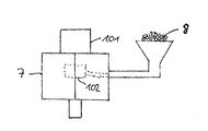
도 3은 도 1의 실시예에 따른 밸브 몸체를 제조하기 위한 제 1 방법의 하나의 방법 단계를 개락적인 측면도로 보여주며,
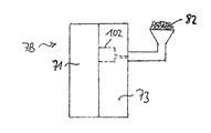
도 4a는 도 1의 실시예에 따른 밸브 몸체를 제조하기 방법의 예시적인 제 2 실시예의 제 1 방법 단계를 개략적인 측면도로 보여주며,
도 4a는 상기 방법의 예시적인 제 2 실시예의 제 2 방법 단계를 개략적인 측면도로 보여준다.1 shows a schematic cross-sectional view of an exemplary embodiment of a valve body,
Figure 2 shows an exemplary embodiment of a fluid injection valve in accordance with an exemplary embodiment in a schematic cross-sectional view,
Fig. 3 shows, in a schematic side view, one method step of a first method for manufacturing a valve body according to the embodiment of Fig. 1,
Figure 4a shows a schematic side view of a first method step of a second exemplary embodiment of a method of manufacturing a valve body according to the embodiment of Figure 1,
Figure 4a shows a schematic side view of a second method step of a second exemplary embodiment of the method.
예시적인 실시예들 및 도면들에서, 유사하거나, 동일하거나, 또는 동일하게 작용하는 요소들에는 동일한 도면부호들이 제공된다. 도면들 및 도면들에서 개별 요소들의 크기 관계들은 스케일에 맞는 것으로 고려되지 않는다. 오히려, 개별 요소들은 더 향상된 묘사 및/또는 이해를 위해 제공되는 크기가 과장될 수 있다.
In the exemplary embodiments and the drawings, the same reference numerals are provided for elements that are similar, identical, or the same. In the Figures and Figures, the size relationships of individual elements are not considered to scale. Rather, the individual elements may be exaggerated in size provided for further description and / or understanding.
도 1은 예시적인 실시예에 따른 밸브 몸체(10)의 개략적인 횡단면도를 보여준다. 밸브 몸체(10)는 길이 방향 축선(L)을 가지며 길이 방향 축선(L)을 따라 유체 입구 부분(2)으로부터 유체 출구 부분(3)으로 연장한다.
1 shows a schematic cross-sectional view of a
밸브 몸체(10)는 기본 몸체(101)를 갖는다. 기본 몸체(101)는 측벽(1011)을 갖는다. 측벽(1011)은 길이 방향 축선(L)을 따라 원주 방향으로 연장하고 오목부(1012)를 형성한다. 오목부(1012)는 밸브 몸체(10)를 통하여 유체 입구 부분(2)으로부터 유체 출구 부분(3)으로 연장한다. 본 실시예에서, 오목부(1012)는 측벽(1011)의 내측 표면에 의해 측방향으로 한정된다. 측벽(1011)의 외측 표면은 오목부(1012)로부터 떨어져 이격된다.
The valve body (10) has a basic body (101). The
기본 몸체(10)는 그 안에 제 1 내경 및 제 1 외경으로서 측벽(1011)을 가지는 제 1 부분 및 제 1 부분의 하류에 제 2 부분을 가질 수 있으며, 측벽(1011)은 제 1 내경 보다 더 작은 제 2 내경을 갖는다. 제 2 부분에서, 측벽(1011)은 제 1 외경보다 더 작은 제 2 외경을 가질 수 있다. 밸브 몸체의 제 1 및 제 2 부분들 사이의 경계면 구역에서, 오목부(1012)는 스텝(step)을 가질 수 있다. 하나의 개선예에서, 밸브 몸체는 제 2 부분의 하류에 제 3 부분을 가지며, 측벽(1011)은 제 3 부분에 제 3 내경을 가지며, 상기 제 3 내경은 제 2 내경보다 크다.
The
밸브 몸체(10)의 기본 몸체(101)의 측벽(1011)은 본 실시예에서의 두 개의 개구(1013)들에 의해 천공된다. 개구들은 본 실시예에서 길이 방향 축선(L)을 포함하고 특히 도 1의 이미지 평면에 대해 수직하게 연장하는 거울면에 대해 거울-대칭 방식으로 배열된다. 개구들은 즉 측벽(1011)의 외측 표면으로부터 측벽(1011)의 내측 표면으로 연장하는, 기본 몸체(101) 내에서 반경 방향으로 연장하는 홀들이다. 개구(1013)들은 특히 기본 몸체(101)의 제 1 부분 내에 배열된다.
The side wall 1011 of the
밸브 몸체(10)는 커버 요소(102)를 더 포함한다. 커버 요소(102)는 기본 몸체(101)의 측벽(1011) 내의 개구(1013)들을 덮도록 배열된다. 적절하게는, 커버 요소(102)는 측벽(1011)의 외측 표면 상에 배열되고 개구(1013)들 내로 반경 방향으로 연장한다. 즉, 커버 요소(102)는 개구(1013)들 내에 수용되는 반경 방향 내측으로 직면하는 돌기들을 갖는다. 커버 요소(102)는 링 형상 방식으로 기본 몸체(101) 주위로 완전히 원주 방향으로 연장한다.
The valve body (10) further includes a cover element (102). The
기본 몸체(101)는 자기 재료인 페라이트계 강, 예를 들면 SAE 430 강으로 이루어진다. 커버 요소는 비-자기 재료인 오스테나이트 강, 예를 들면 SAE 304 강으로 이루어진다.
The
도 2는 예시적인 실시예에 따른 주입 밸브(1)의 개략적인 횡단면도를 보여준다.
Figure 2 shows a schematic cross-sectional view of an injection valve 1 according to an exemplary embodiment.
주입 밸브(101)는 도 1과 관련하여 위에서 설명된 예시적인 실시예에 따라 밸브 몸체(10)를 포함한다. 또한, 주입 밸브(1)는 액추에이터 조립체(20)를 포함한다. 액추에이터 조립체(20)는 밸브 몸체(10)의 오목부(1012) 내에 배열되는 전기자(201)를 포함한다. 또한 밸브 몸체(10) 주위 원주 방향으로 연장하는 코일(202)을 더 포함한다. 자기 회로를 형성하기 위한 폴 피스(204) 및 하우징(203)을 더 포함한다.
The
또한, 유체 주입 밸브(1)는 길이 방향 축선(L)을 따라 주 연장 방향을 가지고 오목부(1012) 내에 배열되는 밸브 니들(30)을 포함한다. 밸브 니들(30)은 본 실시예에서 볼로서 형성된 팁(301) 및 때때로 또한 칼라로 불리는 플랜지(302)를 갖는다. 팁(301)는 유체 출구 부분(3)을 향하여 직면하고 플랜지(302)는 밸브 몸체(10)의 유체 입구 부분(2)를 향하여 직면한다.
The fluid injection valve 1 also includes a
또한, 유체 주입 밸브(1)는 밸브 몸체(10)에 대해 고정된 위치에 있는 밸브 시트(40)를 포함한다. 특히, 밸브 시트(40)는 밸브 몸체(10)의 유체 출구 단부(3)를 폐쇄하며 단지 노즐(401) 만이 개방되어 있다. 밸브 니들이 폐쇄 위치에 있을 때 밸브 니들(30)은 노즐(401)을 통한 유체 유동을 방지하기 위해 그리고 추가 위치들에서 유체 입구 부분(2)으로부터 오목부(1012)를 통하여 유체 출구 부분(3)으로 그리고 노즐(401)을 통하여 유체 유동을 방출하기 위해 밸브 시트(40)와 상호작용하도록 적절히 가동된다.
In addition, the fluid injection valve 1 includes a valve seat 40 in a fixed position relative to the
유체 주입 밸브(1)는 주 스프링(50)을 가지며 주 스프링의 일 단부는 밸브 몸체(10)에 대해 위치가 고정되는 스프링 시트(501)에 커플링된다. 액추에이터 조립체에 동력 공급이 중단되었을 때 유체 주입 밸브(1)가 폐쇄 구성으로 유지하도록 주 스프링(50)의 반대 단부는 밸브 시트(40)를 향하여 밸브 니들(30)을 편향시키기 위해 밸브 니들(30)의 칼라(302)를 지지한다.
The fluid injection valve 1 has a
전기자(201)가 밸브 니들(20)에 대해 축방향으로 가동되는 방식으로 밸브 니들(30)이 전기자(201)의 중앙 개구를 통하여 연장한다. 유체 입구 개구(2)를 향하는 방향으로, 밸브 니들(30)에 대한 전기자(201)의 축방향 운동이 칼라(302)에 의해 제한된다.
The
유체 주입 밸브(1)는 밸브 니들(30)의 칼라(302)를 향하여 전기자(201)를 편향시키도록 전기자(201) 및 밸브 몸체(10)와 기계적으로 상호 작용하는 전기자 스프링(60)을 포함한다. 전기자(201)와 칼라(302)와의 상호 작용을 경유하여 전기자 스프링(60)에 의해 밸브 니들(30)로 전달된 탄성력은 주 스프링(50)에 의해 밸브 니들(30) 상에 가해지는 밸브 시트(40)를 향하는 방향으로 밸브 니들(30) 상의 스프링 로드보다 더 작아서, 액추에이터 조립체(20)에 동력 공급이 중단될 때 밸브를 폐쇄 구성으로 유지한다.
The fluid injection valve 1 includes an
전자기 액추에이터 조립체(20)는 주 스프링(50)의 힘에 대항하여 폐쇄 위치로부터, 즉 유체 입구 부분(2)를 향하여 축방향으로, 멀어지게 밸브 니들(30)을 이동시키기 위해 구성된다. 폴 피스(204)는 기본 몸체(101)의 오목부(1012) 내에 수용되어 오목부에 단단히 커플링되어 폴 피스(204) 및 밸브 몸체(10)가 서로에 대해 위치가 고정된다. 밸브 니들(30)이 폐쇄 위치에 있을 때 전기자(201)가 폴 피스(204)로부터 축방향으로 이격되도록 폴 피스(204)가 위치된다. 폐쇄 위치로부터 밸브 니들(330)을 이동시키기 위해 코일(202)에 동력이 공급될 때, 폴 피스(204)를 향하여 전기자(201)를 이동시키는 자기력이 전기자(201) 상에 가해지며, 이에 의해 전기자(201)와 폴 피스(204) 사이의 축방향 갭을 감소시킨다. 전기자(201)가 폴 피스(204)와 직접적으로 기계적 접촉될 때 유체 주입 밸브(1)는 이의 개방 상태에 도달하도록 구성될 수 있다.
The
밸브 몸체(10)의 기본 몸체(101) 내의 개구(1013)들은 전기자(201)와 축방향으로 겹쳐진다. 즉, 전기자(201)-또는 전기자(201)의 적어도 일 부분-및 커버 요소(102)-또는 커버 요소(102)의 적어도 일 부분은 길이 방향 축선(L)에 대해 동일한 위치들을 공유한다. 이러한 방식으로, 전기자(201)와 코일(202) 사이에 특히 작은 양의 자기 재료가 있다. 따라서, 전기자(201)의 속도 변화들은 코일(202) 내의 특히 높은 유도 신호를 생성한다. 따라서, 전기자(201)의 위치는 특히 정밀하게 검출 가능하다.
The
도 3은 상기 방법의 하나의 단계 동안의 위의 도 1과 관련하여 설명된 예시적인 실시예에 따른 밸브 몸체(10)를 제조하기 위한 방법의 제 1 실시예를 개략적인 측면도로 보여준다.
Figure 3 shows a schematic side view of a first embodiment of a method for manufacturing a
제 1 실시예에 따른 방법에서, 밸브 몸체(10)의 기본 몸체(101)가 제조된다. 하나의 개선예에서, 기본 몸체를 제조하는 단계는 기본 몸체(101)를 기계 가공, 캐스팅 또는 사출 성형하는 단계를 포함한다.
In the method according to the first embodiment, the
후속적으로, 기본 몸체는 몰드(7) 내에 위치된다. 몰드는 적절하게는 도 3에서 점선에 의해 간략하게 표시된 바와 같고 커버 요소의 반대 형상을 가지는 공동을 제공한다.
Subsequently, the basic body is placed in the mold 7. The mold suitably provides a cavity as schematically indicated by the dashed line in Fig. 3 and having the opposite shape of the cover element.
비-자기 재료 및 결합제의 혼합물(8)이 제공된다. 후속적으로, 혼합물(8)은 커버 요소를 성형하기 위해 몰드(7) 내로 주입된다. 몰드(7) 내로의 혼합물(8)의 주입 단계는 결합제를 용융하기 위해 혼합물을 가열하는 단계를 포함할 수 있다. 이 같은 금속 사출 성형 프로세스들은 원칙적으로 당업자에게 알려져 있으며, 따라서 본원에서 더 상세하게 설명하지 않는다.
A mixture (8) of non-magnetic material and binder is provided. Subsequently, the mixture 8 is injected into the mold 7 to form the cover element. The step of injecting the mixture (8) into the mold (7) may comprise heating the mixture to melt the binder. Such metal injection molding processes are known in principle to those skilled in the art and are therefore not described in greater detail herein.
몰드(7)의 형상 및 몰드 내의 기본 몸체(101)의 배열에 의해, 혼합물(8)이 몰드(7) 내에 주입될 때 커버 요소(102)는 기본 몸체(101) 내의 개구(1013)들을 밀봉가능하게 덮는다.
The shape of the mold 7 and the arrangement of the
후속적으로, 몰드(7)는 기본 몸체(101) 및 커버 요소(102)에 의해 성형된 복합체로부터 제거된다. 이어서, 결합제는 비-자기 재료 뒤에 남아 있는, 커버 요소(102)로부터 제거될 수 있다. 커버 요소(102)-특히 기본 몸체(101) 및 커버 요소(102)에 의해 성형된 복합체는 소결된다. 소결 단계는 후속적으로 결합제를 제거하는 단계가 일어날 수 있거나 커버 요소(102)로부터 결합제를 소결하여 제거하는 단계는 하나의 프로세스로 수행될 수 있다.
Subsequently, the mold 7 is removed from the composite molded by the
유용하게는, 커버 요소(102)의 기계적 안정성은 소결에 의해 개선된다. 특히, 비-자기 재료는 혼합물(8)을 제조하기 위해 분말의 형태로 사용된다. 혼합물(8)에서, 분말의 알갱이들은 결합제와 함께 슬러리를 형성할 수 있다. 커버 요소(102)의 소결에 의해, 알갱이들 사이의 단단한 연결은 예를 들면 알갱이들의 표면 구역들의 용융에 의해 형성될 수 있다. 이러한 방식으로, 소결 단계는 또한 커버 요소(102)와 기본 몸체(101) 사이의 특히 우수한 접촉에 기여할 수 있어 개구(1013)들의 특별히 타이트한 밀봉이 달성가능하다.
Advantageously, the mechanical stability of the
도 4a 및 도 4b는 두 개의 후속하는 방법 단계들 동안 밸브 몸체(10)를 제조하기 위한 방법의 예시적인 제 2 실시예를 개략적인 측면도들로 보여준다.
Figures 4a and 4b show schematic side views of an exemplary second embodiment of a method for manufacturing the
예시적인 제 2 실시예에 따른 방법에서, 제 1 몰드 부분(71)이 제공된다. 제 1 몰드(7A)는 제 1 몰드 부분(71) 및 제 2 몰드 부분(72)(도 4a 참조)을 이용하여 조립된다. 코어 및/또는 하나 또는 둘 이상의 삽입 부재들과 같은 추가의 피스들(도면들에 도시안됨)은 제 1 몰드(7A)를 조립하기 위해 부가적으로 사용될 수 있다.
In the method according to the second exemplary embodiment, a
자기 재료 및 결합제를 포함하는 제 1 혼합물(81)이 제공된다. 제 1 몰드(7A)는 도 4a에서 제 2 몰드 부분(72) 내에 점선으로 표시된 바와 같이 기본 몸체(101)의 반대 형상을 가지는 공동을 가질 수 있다. 제 1 혼합물(81)은 기본 몸체(101)를 성형하기 위해 제 1 몰드(7a)의 공동 내로 주입된다. 이러한 방법 단계의 마지막에서, 기본 몸체(101)는 소위 성형체, 즉 자기 재료 및 결합제를 포함하는, 소결되지 않은 워크피스 상태에 있다
A
후속적으로, 제 2 몰드 부분(72)이 제거된다. 제 2 몰드(7B)는 제 1 몰드 부분(71) 및 제 3 몰드 부분(73)을 이용하여 조립된다. 코어 및/또는 하나 또는 둘 이상의 삽입 부재들과 같은 피스들(도면들에 도시안됨)은 제 2 몰드(7B)를 조립하기 위해 부가적으로 사용될 수 있다.
Subsequently, the
기본 몸체는 제 2 몰드(7B) 내에 배열된다. 바람직하게는, 기본 몸체(101)는 제 1 몰드(7A)의 조립 해제 및 제 2 몰드(7B)의 조립 동안 제 1 몰드 부분(71) 내에 남아 있다. 이러한 방식으로, 기본 몸체(101)의 손상 위험이 특히 낮아질 수 있다.
The basic body is arranged in the second mold 7B. Preferably, the
제 2 몰드(7B)는 도 4b에서 제 3 몰드 부분(73) 내에서 점선들에 의해 표시된 바와 같이 커버 요소(102)의 반대 형상을 가지는 공동을 가질 수 있다. 비-자기 재료 및 결합제를 포함하는 제 2 혼합물(82)이 제공되며, 제 2 몰드(7B)의 공동 내로 주입된다.
The second mold 7B may have a cavity with the opposite shape of the
이러한 방식으로, 기본 몸체(101) 및 커버 요소(102)를 포함하는 복합 성형체가 제조된다. 후속적으로, 결합제는 복합 성형체로부터 제거될 수 있다. 복합 성형체가 소결되고, 바람직하게는 후속적으로 결합제가 제거된다. 복합 성형체의 제조 및 기본 몸체(101) 및 커버 요소(102)의 동시 소결은 개구(1013)들의 에지들에서 커버 요소(102)와 기본 몸체(101) 사이의 유체-타이트 연결을 보장하기 위해 특히 유용하다.
In this manner, a composite formed body including the
본 발명은 이러한 실시예들과 관련한 설명에 의해 예시적인 실시예들로 제한되지 않는다. 오히려, 본 발명은 상이한 실시예들의 요소들의 어떠한 조합도 포함한다. 더욱이, 본 발명은 청구항들의 어떠한 조합도 그리고 청구항들에 의해 공개된 특징들의 어떠한 조합도 포함한다.The present invention is not limited to the exemplary embodiments described with reference to these embodiments. Rather, the invention includes any combination of the elements of the different embodiments. Moreover, the present invention includes any combination of the claims and any combination of features disclosed by the claims.
Claims (12)
상기 측벽(1011)은 자기 재료를 포함하며 상기 측벽(1011)을 천공하는 하나 이상의 개구(1013)를 가지며,
상기 밸브 몸체(10)는 비-자기 재료를 포함하고 상기 하나 이상의 개구(1013)를 밀봉되게 덮도록 배열되는 커버 요소(102)를 포함하는,
유체 주입 밸브용 밸브 몸체.
The valve body 10 includes a basic body 101 with a longitudinal axis L and the basic body 101 has a recess 1012 extending axially through the basic body 101 A valve body (10) for a fluid injection valve (1) having a side wall (1011)
The side wall 1011 includes a magnetic material and has at least one opening 1013 for perforating the side wall 1011,
The valve body (10) includes a cover element (102) that includes a non-magnetic material and is arranged to sealably cover the at least one opening (1013)
Valve body for fluid injection valve.
상기 커버 요소(102)는 상기 기본 몸체(101) 주위 원주 방향으로 완전히 연장하는,
유체 주입 밸브용 밸브 몸체.
The method according to claim 1,
The cover element (102) extends completely circumferentially around the basic body (101)
Valve body for fluid injection valve.
상기 커버 요소(102)는 상기 하나 이상의 개구(1013)를 적어도 부분적으로 채우는,
유체 주입 밸브용 밸브 몸체.
3. The method according to claim 1 or 2,
The cover element (102) is configured to at least partially fill the at least one opening (1013)
Valve body for fluid injection valve.
상기 기본 몸체(101)는 페라이트계 강을 포함하고 및/또는 상기 커버 요소(102)는 오스테나이트 강을 포함하는,
유체 주입 밸브용 밸브 몸체.
4. The method according to any one of claims 1 to 3,
Wherein the base body (101) comprises ferritic steel and / or the cover element (102) comprises austenite steel.
Valve body for fluid injection valve.
상기 밸브 몸체(10)는 길이 방향 축선(L)을 포함하는 거울면에 대해 거울 대칭이거나 길이 방향 축선(L)에 대해 n-회 회전 대칭(n-fold rotational symmetry)인,
유체 주입 밸브용 밸브 몸체.
5. The method according to any one of claims 1 to 4,
Wherein the valve body 10 is mirror symmetrical with respect to a mirror plane including the longitudinal axis L or with an n-fold rotational symmetry with respect to the longitudinal axis L,
Valve body for fluid injection valve.
상기 전자기 액추에이터 조립체(20)는 상기 오목부(1012) 내에 배열되고 하나 이상의 개구(1013)와 축방향으로 겹쳐지는 전기자(201)를 포함하는,
유체 주입 밸브.
A fluid injection valve (1) comprising a valve body (10) and an electromagnetic actuator assembly (20) according to any one of claims 1 to 5,
The electromagnetic actuator assembly (20) includes an armature (201) arranged in the recess (1012) and axially overlapped with at least one opening (1013)
Fluid injection valve.
기본 몸체(101)가 오목부(1012)를 형성하는 측벽(1011)을 가지도록, 자기 재료를 포함하는 상기 기본 몸체(101)를 제조하는 단계로서, 상기 오목부(1012)는 상기 기본 몸체(101)를 통하여 축 방향으로 연장하고 상기 측벽(1011)은 하나 이상의 개구(1013)를 가지는, 단계,
비-자기 재료를 포함하는 커버 요소(102)를 제조하고 상기 하나 이상의 개구(1013)를 밀봉되게 덮도록 상기 커버 요소(102)를 배열하는 단계를 포함하는,
유체 주입 밸브용 밸브 몸체의 제조 방법.
1. A method for manufacturing a valve body (10) for a fluid injection valve (1) having a longitudinal axis (L)
A method of manufacturing the basic body (101) comprising a magnetic material such that the basic body (101) has a side wall (1011) forming a recess (1012), the recess (1012) 101 and the sidewall 1011 has at least one opening 1013,
Comprising the step of fabricating a cover element (102) comprising non-magnetic material and arranging the cover element (102) to sealably cover the at least one opening (1013).
A method for manufacturing a valve body for a fluid injection valve.
상기 커버(102)를 제조하는 단계는
몰드(7; 7B) 및 비-자기 재료와 결합제의 혼합물(8; 82)을 제공하는 단계,
상기 커버 요소(102)를 성형하기 위해 상기 몰드(7; 7B) 내로 상기 혼합물(8; 82)을 주입하는 단계, 및
상기 커버 요소(102)를 소결하는 단계를 포함하는,
유체 주입 밸브용 밸브 몸체의 제조 방법.
8. The method of claim 7,
The step of fabricating the cover (102)
Providing a mold (7; 7B) and a mixture of non-magnetic material and binder (8; 82)
Injecting the mixture (8; 82) into the mold (7; 7B) to form the cover element (102)
And sintering the cover element (102).
A method for manufacturing a valve body for a fluid injection valve.
상기 혼합물(8; 82)이 주입되기 전에 상기 기본 몸체(101)가 상기 몰드(7; 7B) 내에 배열되는,
유체 주입 밸브용 밸브 몸체의 제조 방법.
9. The method of claim 8,
Wherein the basic body (101) is arranged in the mold (7; 7B) before the mixture (8; 82)
A method for manufacturing a valve body for a fluid injection valve.
상기 기본 몸체(101) 및 상기 커버 요소(102)를 포함하는 복합 성형체(composite green body)가 제조되고, 상기 복합 성형체가 소결되는 것을 특징으로 하는,
유체 주입 밸브용 밸브 몸체의 제조 방법.
8. The method of claim 7,
Characterized in that a composite green body comprising the basic body (101) and the cover element (102) is produced and the composite formed body is sintered.
A method for manufacturing a valve body for a fluid injection valve.
상기 복합 성형체를 제조하는 단계는
제 1 몰드 부분(71)을 제공하는 단계,
제 2 몰드 부분(72) 및 제 1 혼합물(81)을 제공하는 단계로서, 상기 제 1 혼합물(81)은 자기 재료 및 결합제를 포함하는, 단계,
제 1 몰드 부분(71) 및 제 2 몰드 부분(72)을 포함하는 제 1 몰드(7A)를 조립하고 상기 기본 몸체(101)를 성형하기 위해 상기 제 1 혼합물(81)을 상기 제 1 몰드(7A) 내로 주입하는 단계,
제 3 몰드 부분(73) 및 비-자기 재료 및 결합제를 포함하는 제 2 혼합물(82)을 제공하는 단계,
제 1 몰드 부분(71) 및 제 3 몰드 부분(73)을 포함하는 제 2 몰드(7B)를 조립하고 상기 커버 요소(102)를 성형 및 배열하기 위해 상기 제 2 혼합물(82)을 상기 제 2 몰드(7B) 내로 주입하는 단계를 포함하는,
유체 주입 밸브용 밸브 몸체의 제조 방법.
11. The method of claim 10,
The step of manufacturing the complex formed article
Providing a first mold portion 71,
Providing a second mold part (72) and a first mixture (81), wherein the first mixture (81) comprises a magnetic material and a binder,
A first mold (7A) including a first mold part (71) and a second mold part (72) is assembled and the first mixture (81) is molded into the first mold 7A,
Providing a third mold portion 73 and a second mixture 82 comprising a non-magnetic material and a binder,
A method of assembling a second mold (7B) comprising a first mold part (71) and a third mold part (73) and assembling the second mixture (82) Into mold (7B). ≪ RTI ID = 0.0 >
A method for manufacturing a valve body for a fluid injection valve.
상기 제 2 혼합물(82)이 주입되기 전에 상기 기본 몸체(101)가 상기 제 2 몰드(7B)에 위치되는,
유체 주입 밸브용 밸브 몸체의 제조 방법.12. The method of claim 11,
Wherein the basic body (101) is located in the second mold (7B) before the second mixture (82) is injected,
A method for manufacturing a valve body for a fluid injection valve.
Applications Claiming Priority (2)
| Application Number | Priority Date | Filing Date | Title |
|---|---|---|---|
| EPEP12196957 | 2012-12-13 | ||
| EP12196957.0A EP2743491B1 (en) | 2012-12-13 | 2012-12-13 | Valve body, fluid injection valve and method for producing a valve body |
Publications (2)
| Publication Number | Publication Date |
|---|---|
| KR20140077126A true KR20140077126A (en) | 2014-06-23 |
| KR102107352B1 KR102107352B1 (en) | 2020-05-08 |
Family
ID=47520712
Family Applications (1)
| Application Number | Title | Priority Date | Filing Date |
|---|---|---|---|
| KR1020130155586A Expired - Fee Related KR102107352B1 (en) | 2012-12-13 | 2013-12-13 | Valve body, fluid injection valve and method for producing a valve body |
Country Status (4)
| Country | Link |
|---|---|
| US (1) | US9086042B2 (en) |
| EP (1) | EP2743491B1 (en) |
| KR (1) | KR102107352B1 (en) |
| CN (1) | CN103867366B (en) |
Families Citing this family (5)
| Publication number | Priority date | Publication date | Assignee | Title |
|---|---|---|---|---|
| EP2775132A1 (en) * | 2013-03-07 | 2014-09-10 | Continental Automotive GmbH | Valve body and fluid injector |
| DE102014215466A1 (en) * | 2014-08-05 | 2016-02-11 | Robert Bosch Gmbh | magnetic valve |
| EP3615254B1 (en) * | 2017-04-27 | 2021-02-17 | Federal-Mogul Valvetrain GmbH | Method of manufacturing a poppet valve |
| JP6814724B2 (en) * | 2017-12-22 | 2021-01-20 | 大同特殊鋼株式会社 | solenoid valve |
| EP4031786B1 (en) * | 2019-09-16 | 2026-05-06 | Pierburg GmbH | Solenoid valve for a motor vehicle and method for producing a movement unit from an armature and a valve unit for a solenoid valve of this kind |
Citations (4)
| Publication number | Priority date | Publication date | Assignee | Title |
|---|---|---|---|---|
| EP1055812A2 (en) * | 1999-05-26 | 2000-11-29 | Siemens Automotive Corporation | Compressed natural gas fuel injector |
| US20060028311A1 (en) * | 2002-08-02 | 2006-02-09 | Volker Burger | Electromagnetic actuating device |
| WO2011076535A1 (en) * | 2009-12-22 | 2011-06-30 | Robert Bosch Gmbh | Pole core for magnetic valves produced by means of multi-material mim |
| JP2011137442A (en) * | 2009-12-04 | 2011-07-14 | Denso Corp | Fuel injection valve |
Family Cites Families (17)
| Publication number | Priority date | Publication date | Assignee | Title |
|---|---|---|---|---|
| CA1192174A (en) * | 1981-10-14 | 1985-08-20 | William L. Sheppard | Magnetic air valve |
| US5106053A (en) * | 1988-08-26 | 1992-04-21 | Borg-Warner Automotive Electronic & Mechanical Systems Corporation | Solenoid operated hydraulic control valve |
| US5024418A (en) * | 1989-09-07 | 1991-06-18 | Eaton Corporation | Fluid flow rate control device |
| DE4217871A1 (en) * | 1992-05-29 | 1993-12-02 | Thomas Magnete Gmbh | Electromagnet with armature provided with a rod |
| JP3473884B2 (en) * | 1996-07-29 | 2003-12-08 | 三菱電機株式会社 | Fuel injection valve |
| DE19734845C1 (en) * | 1997-08-12 | 1998-11-12 | Deutsch Zentr Luft & Raumfahrt | Rapid-action valve for space vehicle steering circuits |
| JP2001132582A (en) * | 1999-11-10 | 2001-05-15 | Mitsubishi Electric Corp | In-cylinder fuel injection valve |
| JP2003185051A (en) * | 2001-12-13 | 2003-07-03 | Denso Corp | Solenoid valve device and method of manufacturing the same |
| CN1908386A (en) * | 2005-08-02 | 2007-02-07 | 丰田自动车株式会社 | Electromagnetically driven valve |
| DE102007008863A1 (en) * | 2005-08-26 | 2008-08-28 | Robert Bosch Gmbh | Fuel injector |
| DE102007004799A1 (en) * | 2007-01-31 | 2008-08-07 | Robert Bosch Gmbh | metering |
| DE102008000797B4 (en) * | 2007-03-26 | 2014-05-22 | Denso Corporation | Solenoid valve and fuel injector with the same |
| JP2009127445A (en) * | 2007-11-20 | 2009-06-11 | Denso Corp | Fuel injection valve |
| JP4591593B2 (en) * | 2008-02-13 | 2010-12-01 | 株式会社デンソー | Fuel injection valve |
| ATE487875T1 (en) * | 2008-06-27 | 2010-11-15 | Fiat Ricerche | FUEL INJECTION DEVICE WITH SYMMETRIC MEASUREMENT SERVO VALVE FOR AN INTERNAL COMBUSTION ENGINE |
| JP5101456B2 (en) * | 2008-10-21 | 2012-12-19 | 三菱重工業株式会社 | Solenoid solenoid valve device |
| JP5442980B2 (en) * | 2008-11-06 | 2014-03-19 | カヤバ工業株式会社 | solenoid |
-
2012
- 2012-12-13 EP EP12196957.0A patent/EP2743491B1/en not_active Not-in-force
-
2013
- 2013-11-12 US US14/077,361 patent/US9086042B2/en active Active
- 2013-12-13 KR KR1020130155586A patent/KR102107352B1/en not_active Expired - Fee Related
- 2013-12-13 CN CN201310677929.3A patent/CN103867366B/en not_active Expired - Fee Related
Patent Citations (4)
| Publication number | Priority date | Publication date | Assignee | Title |
|---|---|---|---|---|
| EP1055812A2 (en) * | 1999-05-26 | 2000-11-29 | Siemens Automotive Corporation | Compressed natural gas fuel injector |
| US20060028311A1 (en) * | 2002-08-02 | 2006-02-09 | Volker Burger | Electromagnetic actuating device |
| JP2011137442A (en) * | 2009-12-04 | 2011-07-14 | Denso Corp | Fuel injection valve |
| WO2011076535A1 (en) * | 2009-12-22 | 2011-06-30 | Robert Bosch Gmbh | Pole core for magnetic valves produced by means of multi-material mim |
Also Published As
| Publication number | Publication date |
|---|---|
| CN103867366B (en) | 2018-01-26 |
| US20140166120A1 (en) | 2014-06-19 |
| KR102107352B1 (en) | 2020-05-08 |
| EP2743491A1 (en) | 2014-06-18 |
| US9086042B2 (en) | 2015-07-21 |
| EP2743491B1 (en) | 2015-08-12 |
| CN103867366A (en) | 2014-06-18 |
Similar Documents
| Publication | Publication Date | Title |
|---|---|---|
| JP4589387B2 (en) | Injection valve for fuel injection | |
| US8931718B2 (en) | Valve assembly for an injection valve and injection valve | |
| KR102107352B1 (en) | Valve body, fluid injection valve and method for producing a valve body | |
| US9803606B2 (en) | Fuel injector and method for forming spray-discharge openings | |
| EP2796703A1 (en) | Valve assembly for an injection valve and injection valve | |
| JP4082929B2 (en) | Fuel injection valve | |
| KR101857463B1 (en) | Valve assembly for an injection valve, injection valve and method for assembling a valve assembly of an injection valve | |
| CN104583576B (en) | Valve assemblies and injection valves for injection valves | |
| EP2589786A1 (en) | Valve assembly for a control valve and control valve | |
| US20150260138A1 (en) | Valve Assembly for an Injection Valve and Injection Valve | |
| EP2837813B1 (en) | Valve assembly for an injection valve and injection valve | |
| US10641221B2 (en) | Electromagnetic injection valve and method for assembling an electromagnetic injection valve | |
| EP3009655B1 (en) | Fuel injection valve for an internal combustion engine | |
| JP2002531751A (en) | Fuel injection valve | |
| EP2719886B1 (en) | Valve assembly for an injection valve | |
| JP5101705B2 (en) | Fuel injection valve | |
| EP2568155B1 (en) | Valve assembly and injection valve | |
| EP2863043B1 (en) | Fuel injector | |
| JP2001193596A (en) | Needle valve | |
| EP2436909A1 (en) | Valve assembly for an injection valve and injection valve | |
| EP2466109A1 (en) | Valve assembly for an injection valve and injection valve | |
| EP2385239A1 (en) | Valve assembly for an injection valve and injection valve | |
| JP2007278303A (en) | Fuel injection valve | |
| EP2703634A1 (en) | Valve assembly for an injection valve and injection valve | |
| EP2363595A1 (en) | Valve assembly for an injection valve and injection valve |
Legal Events
| Date | Code | Title | Description |
|---|---|---|---|
| PA0109 | Patent application |
St.27 status event code: A-0-1-A10-A12-nap-PA0109 |
|
| PG1501 | Laying open of application |
St.27 status event code: A-1-1-Q10-Q12-nap-PG1501 |
|
| A201 | Request for examination | ||
| PA0201 | Request for examination |
St.27 status event code: A-1-2-D10-D11-exm-PA0201 |
|
| E902 | Notification of reason for refusal | ||
| PE0902 | Notice of grounds for rejection |
St.27 status event code: A-1-2-D10-D21-exm-PE0902 |
|
| P11-X000 | Amendment of application requested |
St.27 status event code: A-2-2-P10-P11-nap-X000 |
|
| P13-X000 | Application amended |
St.27 status event code: A-2-2-P10-P13-nap-X000 |
|
| E701 | Decision to grant or registration of patent right | ||
| PE0701 | Decision of registration |
St.27 status event code: A-1-2-D10-D22-exm-PE0701 |
|
| GRNT | Written decision to grant | ||
| PR0701 | Registration of establishment |
St.27 status event code: A-2-4-F10-F11-exm-PR0701 |
|
| PR1002 | Payment of registration fee |
St.27 status event code: A-2-2-U10-U11-oth-PR1002 Fee payment year number: 1 |
|
| PG1601 | Publication of registration |
St.27 status event code: A-4-4-Q10-Q13-nap-PG1601 |
|
| P22-X000 | Classification modified |
St.27 status event code: A-4-4-P10-P22-nap-X000 |
|
| PR1001 | Payment of annual fee |
St.27 status event code: A-4-4-U10-U11-oth-PR1001 Fee payment year number: 4 |
|
| PN2301 | Change of applicant |
St.27 status event code: A-5-5-R10-R11-asn-PN2301 |
|
| PN2301 | Change of applicant |
St.27 status event code: A-5-5-R10-R14-asn-PN2301 |
|
| PC1903 | Unpaid annual fee |
St.27 status event code: A-4-4-U10-U13-oth-PC1903 Not in force date: 20240429 Payment event data comment text: Termination Category : DEFAULT_OF_REGISTRATION_FEE |
|
| PC1903 | Unpaid annual fee |
St.27 status event code: N-4-6-H10-H13-oth-PC1903 Ip right cessation event data comment text: Termination Category : DEFAULT_OF_REGISTRATION_FEE Not in force date: 20240429 |