KR20140077126A - 밸브 몸체, 유체 주입 밸브 및 밸브 몸체를 제조하기 위한 방법 - Google Patents
밸브 몸체, 유체 주입 밸브 및 밸브 몸체를 제조하기 위한 방법 Download PDFInfo
- Publication number
- KR20140077126A KR20140077126A KR1020130155586A KR20130155586A KR20140077126A KR 20140077126 A KR20140077126 A KR 20140077126A KR 1020130155586 A KR1020130155586 A KR 1020130155586A KR 20130155586 A KR20130155586 A KR 20130155586A KR 20140077126 A KR20140077126 A KR 20140077126A
- Authority
- KR
- South Korea
- Prior art keywords
- valve
- valve body
- fluid injection
- mold
- cover element
- Prior art date
- Legal status (The legal status is an assumption and is not a legal conclusion. Google has not performed a legal analysis and makes no representation as to the accuracy of the status listed.)
- Granted
Links
Images



Classifications
-
- F—MECHANICAL ENGINEERING; LIGHTING; HEATING; WEAPONS; BLASTING
- F02—COMBUSTION ENGINES; HOT-GAS OR COMBUSTION-PRODUCT ENGINE PLANTS
- F02M—SUPPLYING COMBUSTION ENGINES IN GENERAL WITH COMBUSTIBLE MIXTURES OR CONSTITUENTS THEREOF
- F02M51/00—Fuel-injection apparatus characterised by being operated electrically
- F02M51/06—Injectors peculiar thereto with means directly operating the valve needle
- F02M51/061—Injectors peculiar thereto with means directly operating the valve needle using electromagnetic operating means
- F02M51/0614—Injectors peculiar thereto with means directly operating the valve needle using electromagnetic operating means characterised by arrangement of electromagnets or fixed armature
-
- F—MECHANICAL ENGINEERING; LIGHTING; HEATING; WEAPONS; BLASTING
- F02—COMBUSTION ENGINES; HOT-GAS OR COMBUSTION-PRODUCT ENGINE PLANTS
- F02M—SUPPLYING COMBUSTION ENGINES IN GENERAL WITH COMBUSTIBLE MIXTURES OR CONSTITUENTS THEREOF
- F02M51/00—Fuel-injection apparatus characterised by being operated electrically
- F02M51/06—Injectors peculiar thereto with means directly operating the valve needle
- F02M51/061—Injectors peculiar thereto with means directly operating the valve needle using electromagnetic operating means
- F02M51/0625—Injectors peculiar thereto with means directly operating the valve needle using electromagnetic operating means characterised by arrangement of mobile armatures
- F02M51/0664—Injectors peculiar thereto with means directly operating the valve needle using electromagnetic operating means characterised by arrangement of mobile armatures having a cylindrically or partly cylindrically shaped armature, e.g. entering the winding; having a plate-shaped or undulated armature entering the winding
- F02M51/0685—Injectors peculiar thereto with means directly operating the valve needle using electromagnetic operating means characterised by arrangement of mobile armatures having a cylindrically or partly cylindrically shaped armature, e.g. entering the winding; having a plate-shaped or undulated armature entering the winding the armature and the valve being allowed to move relatively to each other or not being attached to each other
-
- F—MECHANICAL ENGINEERING; LIGHTING; HEATING; WEAPONS; BLASTING
- F02—COMBUSTION ENGINES; HOT-GAS OR COMBUSTION-PRODUCT ENGINE PLANTS
- F02M—SUPPLYING COMBUSTION ENGINES IN GENERAL WITH COMBUSTIBLE MIXTURES OR CONSTITUENTS THEREOF
- F02M61/00—Fuel-injectors not provided for in groups F02M39/00 - F02M57/00 or F02M67/00
- F02M61/16—Details not provided for in, or of interest apart from, the apparatus of groups F02M61/02 - F02M61/14
- F02M61/166—Selection of particular materials
-
- F—MECHANICAL ENGINEERING; LIGHTING; HEATING; WEAPONS; BLASTING
- F02—COMBUSTION ENGINES; HOT-GAS OR COMBUSTION-PRODUCT ENGINE PLANTS
- F02M—SUPPLYING COMBUSTION ENGINES IN GENERAL WITH COMBUSTIBLE MIXTURES OR CONSTITUENTS THEREOF
- F02M61/00—Fuel-injectors not provided for in groups F02M39/00 - F02M57/00 or F02M67/00
- F02M61/16—Details not provided for in, or of interest apart from, the apparatus of groups F02M61/02 - F02M61/14
- F02M61/168—Assembling; Disassembling; Manufacturing; Adjusting
-
- F—MECHANICAL ENGINEERING; LIGHTING; HEATING; WEAPONS; BLASTING
- F02—COMBUSTION ENGINES; HOT-GAS OR COMBUSTION-PRODUCT ENGINE PLANTS
- F02M—SUPPLYING COMBUSTION ENGINES IN GENERAL WITH COMBUSTIBLE MIXTURES OR CONSTITUENTS THEREOF
- F02M65/00—Testing fuel-injection apparatus, e.g. testing injection timing ; Cleaning of fuel-injection apparatus
- F02M65/005—Measuring or detecting injection-valve lift, e.g. to determine injection timing
-
- F—MECHANICAL ENGINEERING; LIGHTING; HEATING; WEAPONS; BLASTING
- F16—ENGINEERING ELEMENTS AND UNITS; GENERAL MEASURES FOR PRODUCING AND MAINTAINING EFFECTIVE FUNCTIONING OF MACHINES OR INSTALLATIONS; THERMAL INSULATION IN GENERAL
- F16K—VALVES; TAPS; COCKS; ACTUATING-FLOATS; DEVICES FOR VENTING OR AERATING
- F16K29/00—Arrangements for movement of valve members other than for opening and closing the valve, e.g. for grinding-in, for preventing sticking
-
- F—MECHANICAL ENGINEERING; LIGHTING; HEATING; WEAPONS; BLASTING
- F02—COMBUSTION ENGINES; HOT-GAS OR COMBUSTION-PRODUCT ENGINE PLANTS
- F02M—SUPPLYING COMBUSTION ENGINES IN GENERAL WITH COMBUSTIBLE MIXTURES OR CONSTITUENTS THEREOF
- F02M2200/00—Details of fuel-injection apparatus, not otherwise provided for
- F02M2200/08—Fuel-injection apparatus having special means for influencing magnetic flux, e.g. for shielding or guiding magnetic flux
-
- F—MECHANICAL ENGINEERING; LIGHTING; HEATING; WEAPONS; BLASTING
- F02—COMBUSTION ENGINES; HOT-GAS OR COMBUSTION-PRODUCT ENGINE PLANTS
- F02M—SUPPLYING COMBUSTION ENGINES IN GENERAL WITH COMBUSTIBLE MIXTURES OR CONSTITUENTS THEREOF
- F02M2200/00—Details of fuel-injection apparatus, not otherwise provided for
- F02M2200/80—Fuel injection apparatus manufacture, repair or assembly
- F02M2200/8046—Fuel injection apparatus manufacture, repair or assembly the manufacture involving injection moulding, e.g. of plastic or metal
-
- F—MECHANICAL ENGINEERING; LIGHTING; HEATING; WEAPONS; BLASTING
- F02—COMBUSTION ENGINES; HOT-GAS OR COMBUSTION-PRODUCT ENGINE PLANTS
- F02M—SUPPLYING COMBUSTION ENGINES IN GENERAL WITH COMBUSTIBLE MIXTURES OR CONSTITUENTS THEREOF
- F02M2200/00—Details of fuel-injection apparatus, not otherwise provided for
- F02M2200/90—Selection of particular materials
- F02M2200/9053—Metals
- F02M2200/9069—Non-magnetic metals
-
- F—MECHANICAL ENGINEERING; LIGHTING; HEATING; WEAPONS; BLASTING
- F02—COMBUSTION ENGINES; HOT-GAS OR COMBUSTION-PRODUCT ENGINE PLANTS
- F02M—SUPPLYING COMBUSTION ENGINES IN GENERAL WITH COMBUSTIBLE MIXTURES OR CONSTITUENTS THEREOF
- F02M2200/00—Details of fuel-injection apparatus, not otherwise provided for
- F02M2200/90—Selection of particular materials
- F02M2200/9092—Sintered materials
-
- Y—GENERAL TAGGING OF NEW TECHNOLOGICAL DEVELOPMENTS; GENERAL TAGGING OF CROSS-SECTIONAL TECHNOLOGIES SPANNING OVER SEVERAL SECTIONS OF THE IPC; TECHNICAL SUBJECTS COVERED BY FORMER USPC CROSS-REFERENCE ART COLLECTIONS [XRACs] AND DIGESTS
- Y10—TECHNICAL SUBJECTS COVERED BY FORMER USPC
- Y10T—TECHNICAL SUBJECTS COVERED BY FORMER US CLASSIFICATION
- Y10T137/00—Fluid handling
- Y10T137/0318—Processes
- Y10T137/0402—Cleaning, repairing, or assembling
- Y10T137/0491—Valve or valve element assembling, disassembling, or replacing
-
- Y—GENERAL TAGGING OF NEW TECHNOLOGICAL DEVELOPMENTS; GENERAL TAGGING OF CROSS-SECTIONAL TECHNOLOGIES SPANNING OVER SEVERAL SECTIONS OF THE IPC; TECHNICAL SUBJECTS COVERED BY FORMER USPC CROSS-REFERENCE ART COLLECTIONS [XRACs] AND DIGESTS
- Y10—TECHNICAL SUBJECTS COVERED BY FORMER USPC
- Y10T—TECHNICAL SUBJECTS COVERED BY FORMER US CLASSIFICATION
- Y10T137/00—Fluid handling
- Y10T137/6851—With casing, support, protector or static constructional installations
Landscapes
- Engineering & Computer Science (AREA)
- General Engineering & Computer Science (AREA)
- Mechanical Engineering (AREA)
- Chemical & Material Sciences (AREA)
- Combustion & Propulsion (AREA)
- Physics & Mathematics (AREA)
- Electromagnetism (AREA)
- Manufacturing & Machinery (AREA)
- Magnetically Actuated Valves (AREA)
- Fuel-Injection Apparatus (AREA)
Abstract
Description
도 2는 개략적인 횡단면도에서 예시적인 실시예에 따라 유체 주입 밸브의 예시적인 실시예를 보여주며,
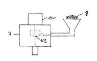
도 3은 도 1의 실시예에 따른 밸브 몸체를 제조하기 위한 제 1 방법의 하나의 방법 단계를 개락적인 측면도로 보여주며,
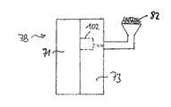
도 4a는 도 1의 실시예에 따른 밸브 몸체를 제조하기 방법의 예시적인 제 2 실시예의 제 1 방법 단계를 개략적인 측면도로 보여주며,
도 4a는 상기 방법의 예시적인 제 2 실시예의 제 2 방법 단계를 개략적인 측면도로 보여준다.
Claims (12)
- 밸브 몸체(10)가 길이 방향 축선(L)을 가지고 기본 몸체(101)를 포함하며, 상기 기본 몸체(101)는 축 방향으로 기본 몸체(101)를 통하여 연장하는 오목부(recess; 1012)를 형성하는 측벽(1011)을 가지는, 유체 주입 밸브(1)용 밸브 몸체(10)로서,
상기 측벽(1011)은 자기 재료를 포함하며 상기 측벽(1011)을 천공하는 하나 이상의 개구(1013)를 가지며,
상기 밸브 몸체(10)는 비-자기 재료를 포함하고 상기 하나 이상의 개구(1013)를 밀봉되게 덮도록 배열되는 커버 요소(102)를 포함하는,
유체 주입 밸브용 밸브 몸체.
- 제 1 항에 있어서,
상기 커버 요소(102)는 상기 기본 몸체(101) 주위 원주 방향으로 완전히 연장하는,
유체 주입 밸브용 밸브 몸체.
- 제 1 항 또는 제 2 항에 있어서,
상기 커버 요소(102)는 상기 하나 이상의 개구(1013)를 적어도 부분적으로 채우는,
유체 주입 밸브용 밸브 몸체.
- 제 1 항 내지 제 3 항 중 어느 한 항에 있어서,
상기 기본 몸체(101)는 페라이트계 강을 포함하고 및/또는 상기 커버 요소(102)는 오스테나이트 강을 포함하는,
유체 주입 밸브용 밸브 몸체.
- 제 1 항 내지 제 4 항 중 어느 한 항에 있어서,
상기 밸브 몸체(10)는 길이 방향 축선(L)을 포함하는 거울면에 대해 거울 대칭이거나 길이 방향 축선(L)에 대해 n-회 회전 대칭(n-fold rotational symmetry)인,
유체 주입 밸브용 밸브 몸체.
- 제 1 항 내지 제 5 항 중 어느 한 항의 밸브 몸체(10) 및 전자기 액추에이터 조립체(20)를 포함하는 유체 주입 밸브(1)로서,
상기 전자기 액추에이터 조립체(20)는 상기 오목부(1012) 내에 배열되고 하나 이상의 개구(1013)와 축방향으로 겹쳐지는 전기자(201)를 포함하는,
유체 주입 밸브.
- 길이 방향 축선(L)을 가지는 유체 주입 밸브(1)용 밸브 몸체(10)를 제조하기 위한 방법으로서,
기본 몸체(101)가 오목부(1012)를 형성하는 측벽(1011)을 가지도록, 자기 재료를 포함하는 상기 기본 몸체(101)를 제조하는 단계로서, 상기 오목부(1012)는 상기 기본 몸체(101)를 통하여 축 방향으로 연장하고 상기 측벽(1011)은 하나 이상의 개구(1013)를 가지는, 단계,
비-자기 재료를 포함하는 커버 요소(102)를 제조하고 상기 하나 이상의 개구(1013)를 밀봉되게 덮도록 상기 커버 요소(102)를 배열하는 단계를 포함하는,
유체 주입 밸브용 밸브 몸체의 제조 방법.
- 제 7 항에 있어서,
상기 커버(102)를 제조하는 단계는
몰드(7; 7B) 및 비-자기 재료와 결합제의 혼합물(8; 82)을 제공하는 단계,
상기 커버 요소(102)를 성형하기 위해 상기 몰드(7; 7B) 내로 상기 혼합물(8; 82)을 주입하는 단계, 및
상기 커버 요소(102)를 소결하는 단계를 포함하는,
유체 주입 밸브용 밸브 몸체의 제조 방법.
- 제 8 항에 있어서,
상기 혼합물(8; 82)이 주입되기 전에 상기 기본 몸체(101)가 상기 몰드(7; 7B) 내에 배열되는,
유체 주입 밸브용 밸브 몸체의 제조 방법.
- 제 7 항에 있어서,
상기 기본 몸체(101) 및 상기 커버 요소(102)를 포함하는 복합 성형체(composite green body)가 제조되고, 상기 복합 성형체가 소결되는 것을 특징으로 하는,
유체 주입 밸브용 밸브 몸체의 제조 방법.
- 제 10 항에 있어서,
상기 복합 성형체를 제조하는 단계는
제 1 몰드 부분(71)을 제공하는 단계,
제 2 몰드 부분(72) 및 제 1 혼합물(81)을 제공하는 단계로서, 상기 제 1 혼합물(81)은 자기 재료 및 결합제를 포함하는, 단계,
제 1 몰드 부분(71) 및 제 2 몰드 부분(72)을 포함하는 제 1 몰드(7A)를 조립하고 상기 기본 몸체(101)를 성형하기 위해 상기 제 1 혼합물(81)을 상기 제 1 몰드(7A) 내로 주입하는 단계,
제 3 몰드 부분(73) 및 비-자기 재료 및 결합제를 포함하는 제 2 혼합물(82)을 제공하는 단계,
제 1 몰드 부분(71) 및 제 3 몰드 부분(73)을 포함하는 제 2 몰드(7B)를 조립하고 상기 커버 요소(102)를 성형 및 배열하기 위해 상기 제 2 혼합물(82)을 상기 제 2 몰드(7B) 내로 주입하는 단계를 포함하는,
유체 주입 밸브용 밸브 몸체의 제조 방법.
- 제 11 항에 있어서,
상기 제 2 혼합물(82)이 주입되기 전에 상기 기본 몸체(101)가 상기 제 2 몰드(7B)에 위치되는,
유체 주입 밸브용 밸브 몸체의 제조 방법.
Applications Claiming Priority (2)
| Application Number | Priority Date | Filing Date | Title |
|---|---|---|---|
| EPEP12196957 | 2012-12-13 | ||
| EP12196957.0A EP2743491B1 (en) | 2012-12-13 | 2012-12-13 | Valve body, fluid injection valve and method for producing a valve body |
Publications (2)
| Publication Number | Publication Date |
|---|---|
| KR20140077126A true KR20140077126A (ko) | 2014-06-23 |
| KR102107352B1 KR102107352B1 (ko) | 2020-05-08 |
Family
ID=47520712
Family Applications (1)
| Application Number | Title | Priority Date | Filing Date |
|---|---|---|---|
| KR1020130155586A Expired - Fee Related KR102107352B1 (ko) | 2012-12-13 | 2013-12-13 | 밸브 몸체, 유체 주입 밸브 및 밸브 몸체를 제조하기 위한 방법 |
Country Status (4)
| Country | Link |
|---|---|
| US (1) | US9086042B2 (ko) |
| EP (1) | EP2743491B1 (ko) |
| KR (1) | KR102107352B1 (ko) |
| CN (1) | CN103867366B (ko) |
Families Citing this family (5)
| Publication number | Priority date | Publication date | Assignee | Title |
|---|---|---|---|---|
| EP2775132A1 (en) * | 2013-03-07 | 2014-09-10 | Continental Automotive GmbH | Valve body and fluid injector |
| DE102014215466A1 (de) * | 2014-08-05 | 2016-02-11 | Robert Bosch Gmbh | Magnetventil |
| EP3615254B1 (en) * | 2017-04-27 | 2021-02-17 | Federal-Mogul Valvetrain GmbH | Method of manufacturing a poppet valve |
| JP6814724B2 (ja) * | 2017-12-22 | 2021-01-20 | 大同特殊鋼株式会社 | 電磁弁 |
| EP4031786B1 (de) * | 2019-09-16 | 2026-05-06 | Pierburg GmbH | Elektromagnetventil für ein kraftfahrzeug und verfahren zur herstellung einer bewegungseinheit aus einem anker und einer ventileinheit für ein derartiges elektromagnetventil |
Citations (4)
| Publication number | Priority date | Publication date | Assignee | Title |
|---|---|---|---|---|
| EP1055812A2 (en) * | 1999-05-26 | 2000-11-29 | Siemens Automotive Corporation | Compressed natural gas fuel injector |
| US20060028311A1 (en) * | 2002-08-02 | 2006-02-09 | Volker Burger | Electromagnetic actuating device |
| WO2011076535A1 (de) * | 2009-12-22 | 2011-06-30 | Robert Bosch Gmbh | Polkern für magnetventile hergestellt mittels mehrstoff-mim |
| JP2011137442A (ja) * | 2009-12-04 | 2011-07-14 | Denso Corp | 燃料噴射弁 |
Family Cites Families (17)
| Publication number | Priority date | Publication date | Assignee | Title |
|---|---|---|---|---|
| CA1192174A (en) * | 1981-10-14 | 1985-08-20 | William L. Sheppard | Magnetic air valve |
| US5106053A (en) * | 1988-08-26 | 1992-04-21 | Borg-Warner Automotive Electronic & Mechanical Systems Corporation | Solenoid operated hydraulic control valve |
| US5024418A (en) * | 1989-09-07 | 1991-06-18 | Eaton Corporation | Fluid flow rate control device |
| DE4217871A1 (de) * | 1992-05-29 | 1993-12-02 | Thomas Magnete Gmbh | Elektromagnet mit mit einer Stange versehenem Anker |
| JP3473884B2 (ja) * | 1996-07-29 | 2003-12-08 | 三菱電機株式会社 | 燃料噴射弁 |
| DE19734845C1 (de) * | 1997-08-12 | 1998-11-12 | Deutsch Zentr Luft & Raumfahrt | Schnellschaltendes Ventil |
| JP2001132582A (ja) * | 1999-11-10 | 2001-05-15 | Mitsubishi Electric Corp | 筒内噴射用燃料噴射弁 |
| JP2003185051A (ja) * | 2001-12-13 | 2003-07-03 | Denso Corp | 電磁弁装置およびその製造方法 |
| CN1908386A (zh) * | 2005-08-02 | 2007-02-07 | 丰田自动车株式会社 | 电磁驱动阀 |
| DE102007008863A1 (de) * | 2005-08-26 | 2008-08-28 | Robert Bosch Gmbh | Brennstoffeinspritzventil |
| DE102007004799A1 (de) * | 2007-01-31 | 2008-08-07 | Robert Bosch Gmbh | Dosiereinrichtung |
| DE102008000797B4 (de) * | 2007-03-26 | 2014-05-22 | Denso Corporation | Elektromagnetventil und Kraftstoffeinspritzventil mit dem selben |
| JP2009127445A (ja) * | 2007-11-20 | 2009-06-11 | Denso Corp | 燃料噴射弁 |
| JP4591593B2 (ja) * | 2008-02-13 | 2010-12-01 | 株式会社デンソー | 燃料噴射弁 |
| ATE487875T1 (de) * | 2008-06-27 | 2010-11-15 | Fiat Ricerche | Kraftstoffeinspritzgerät mit symmetrischem mess- servoventil für einen verbrennungsmotor |
| JP5101456B2 (ja) * | 2008-10-21 | 2012-12-19 | 三菱重工業株式会社 | ソレノイド式電磁弁装置 |
| JP5442980B2 (ja) * | 2008-11-06 | 2014-03-19 | カヤバ工業株式会社 | ソレノイド |
-
2012
- 2012-12-13 EP EP12196957.0A patent/EP2743491B1/en not_active Not-in-force
-
2013
- 2013-11-12 US US14/077,361 patent/US9086042B2/en active Active
- 2013-12-13 KR KR1020130155586A patent/KR102107352B1/ko not_active Expired - Fee Related
- 2013-12-13 CN CN201310677929.3A patent/CN103867366B/zh not_active Expired - Fee Related
Patent Citations (4)
| Publication number | Priority date | Publication date | Assignee | Title |
|---|---|---|---|---|
| EP1055812A2 (en) * | 1999-05-26 | 2000-11-29 | Siemens Automotive Corporation | Compressed natural gas fuel injector |
| US20060028311A1 (en) * | 2002-08-02 | 2006-02-09 | Volker Burger | Electromagnetic actuating device |
| JP2011137442A (ja) * | 2009-12-04 | 2011-07-14 | Denso Corp | 燃料噴射弁 |
| WO2011076535A1 (de) * | 2009-12-22 | 2011-06-30 | Robert Bosch Gmbh | Polkern für magnetventile hergestellt mittels mehrstoff-mim |
Also Published As
| Publication number | Publication date |
|---|---|
| CN103867366B (zh) | 2018-01-26 |
| US20140166120A1 (en) | 2014-06-19 |
| KR102107352B1 (ko) | 2020-05-08 |
| EP2743491A1 (en) | 2014-06-18 |
| US9086042B2 (en) | 2015-07-21 |
| EP2743491B1 (en) | 2015-08-12 |
| CN103867366A (zh) | 2014-06-18 |
Similar Documents
| Publication | Publication Date | Title |
|---|---|---|
| JP4589387B2 (ja) | 燃料噴射用の噴射弁 | |
| US8931718B2 (en) | Valve assembly for an injection valve and injection valve | |
| KR102107352B1 (ko) | 밸브 몸체, 유체 주입 밸브 및 밸브 몸체를 제조하기 위한 방법 | |
| US9803606B2 (en) | Fuel injector and method for forming spray-discharge openings | |
| EP2796703A1 (en) | Valve assembly for an injection valve and injection valve | |
| JP4082929B2 (ja) | 燃料噴射弁 | |
| KR101857463B1 (ko) | 분사 밸브를 위한 밸브 조립체, 분사 밸브 및 분사 밸브의 밸브 조립체를 조립하기 위한 방법 | |
| CN104583576B (zh) | 用于喷射阀的阀组件和喷射阀 | |
| EP2589786A1 (en) | Valve assembly for a control valve and control valve | |
| US20150260138A1 (en) | Valve Assembly for an Injection Valve and Injection Valve | |
| EP2837813B1 (en) | Valve assembly for an injection valve and injection valve | |
| US10641221B2 (en) | Electromagnetic injection valve and method for assembling an electromagnetic injection valve | |
| EP3009655B1 (en) | Fuel injection valve for an internal combustion engine | |
| JP2002531751A (ja) | 燃料噴射弁 | |
| EP2719886B1 (en) | Valve assembly for an injection valve | |
| JP5101705B2 (ja) | 燃料噴射弁 | |
| EP2568155B1 (en) | Valve assembly and injection valve | |
| EP2863043B1 (en) | Fuel injector | |
| JP2001193596A (ja) | ニードルバルブ | |
| EP2436909A1 (en) | Valve assembly for an injection valve and injection valve | |
| EP2466109A1 (en) | Valve assembly for an injection valve and injection valve | |
| EP2385239A1 (en) | Valve assembly for an injection valve and injection valve | |
| JP2007278303A (ja) | 燃料噴射弁 | |
| EP2703634A1 (en) | Valve assembly for an injection valve and injection valve | |
| EP2363595A1 (en) | Valve assembly for an injection valve and injection valve |
Legal Events
| Date | Code | Title | Description |
|---|---|---|---|
| PA0109 | Patent application |
St.27 status event code: A-0-1-A10-A12-nap-PA0109 |
|
| PG1501 | Laying open of application |
St.27 status event code: A-1-1-Q10-Q12-nap-PG1501 |
|
| A201 | Request for examination | ||
| PA0201 | Request for examination |
St.27 status event code: A-1-2-D10-D11-exm-PA0201 |
|
| E902 | Notification of reason for refusal | ||
| PE0902 | Notice of grounds for rejection |
St.27 status event code: A-1-2-D10-D21-exm-PE0902 |
|
| P11-X000 | Amendment of application requested |
St.27 status event code: A-2-2-P10-P11-nap-X000 |
|
| P13-X000 | Application amended |
St.27 status event code: A-2-2-P10-P13-nap-X000 |
|
| E701 | Decision to grant or registration of patent right | ||
| PE0701 | Decision of registration |
St.27 status event code: A-1-2-D10-D22-exm-PE0701 |
|
| GRNT | Written decision to grant | ||
| PR0701 | Registration of establishment |
St.27 status event code: A-2-4-F10-F11-exm-PR0701 |
|
| PR1002 | Payment of registration fee |
St.27 status event code: A-2-2-U10-U11-oth-PR1002 Fee payment year number: 1 |
|
| PG1601 | Publication of registration |
St.27 status event code: A-4-4-Q10-Q13-nap-PG1601 |
|
| P22-X000 | Classification modified |
St.27 status event code: A-4-4-P10-P22-nap-X000 |
|
| PR1001 | Payment of annual fee |
St.27 status event code: A-4-4-U10-U11-oth-PR1001 Fee payment year number: 4 |
|
| PN2301 | Change of applicant |
St.27 status event code: A-5-5-R10-R11-asn-PN2301 |
|
| PN2301 | Change of applicant |
St.27 status event code: A-5-5-R10-R14-asn-PN2301 |
|
| PC1903 | Unpaid annual fee |
St.27 status event code: A-4-4-U10-U13-oth-PC1903 Not in force date: 20240429 Payment event data comment text: Termination Category : DEFAULT_OF_REGISTRATION_FEE |
|
| PC1903 | Unpaid annual fee |
St.27 status event code: N-4-6-H10-H13-oth-PC1903 Ip right cessation event data comment text: Termination Category : DEFAULT_OF_REGISTRATION_FEE Not in force date: 20240429 |