KR20140140499A - 압전 소자 및 그것을 이용한 잉크젯 헤드와 도포 방법 - Google Patents
압전 소자 및 그것을 이용한 잉크젯 헤드와 도포 방법 Download PDFInfo
- Publication number
- KR20140140499A KR20140140499A KR1020140063085A KR20140063085A KR20140140499A KR 20140140499 A KR20140140499 A KR 20140140499A KR 1020140063085 A KR1020140063085 A KR 1020140063085A KR 20140063085 A KR20140063085 A KR 20140063085A KR 20140140499 A KR20140140499 A KR 20140140499A
- Authority
- KR
- South Korea
- Prior art keywords
- region
- electrode
- piezoelectric element
- sheet
- laminate
- Prior art date
- Legal status (The legal status is an assumption and is not a legal conclusion. Google has not performed a legal analysis and makes no representation as to the accuracy of the status listed.)
- Ceased
Links
Images








Classifications
-
- B—PERFORMING OPERATIONS; TRANSPORTING
- B41—PRINTING; LINING MACHINES; TYPEWRITERS; STAMPS
- B41J—TYPEWRITERS; SELECTIVE PRINTING MECHANISMS, i.e. MECHANISMS PRINTING OTHERWISE THAN FROM A FORME; CORRECTION OF TYPOGRAPHICAL ERRORS
- B41J2/00—Typewriters or selective printing mechanisms characterised by the printing or marking process for which they are designed
- B41J2/005—Typewriters or selective printing mechanisms characterised by the printing or marking process for which they are designed characterised by bringing liquid or particles selectively into contact with a printing material
- B41J2/01—Ink jet
- B41J2/135—Nozzles
- B41J2/14—Structure thereof only for on-demand ink jet heads
- B41J2/14201—Structure of print heads with piezoelectric elements
- B41J2/14274—Structure of print heads with piezoelectric elements of stacked structure type, deformed by compression/extension and disposed on a diaphragm
-
- B—PERFORMING OPERATIONS; TRANSPORTING
- B41—PRINTING; LINING MACHINES; TYPEWRITERS; STAMPS
- B41J—TYPEWRITERS; SELECTIVE PRINTING MECHANISMS, i.e. MECHANISMS PRINTING OTHERWISE THAN FROM A FORME; CORRECTION OF TYPOGRAPHICAL ERRORS
- B41J2/00—Typewriters or selective printing mechanisms characterised by the printing or marking process for which they are designed
- B41J2/005—Typewriters or selective printing mechanisms characterised by the printing or marking process for which they are designed characterised by bringing liquid or particles selectively into contact with a printing material
- B41J2/01—Ink jet
- B41J2/015—Ink jet characterised by the jet generation process
- B41J2/04—Ink jet characterised by the jet generation process generating single droplets or particles on demand
- B41J2/045—Ink jet characterised by the jet generation process generating single droplets or particles on demand by pressure, e.g. electromechanical transducers
-
- B—PERFORMING OPERATIONS; TRANSPORTING
- B41—PRINTING; LINING MACHINES; TYPEWRITERS; STAMPS
- B41J—TYPEWRITERS; SELECTIVE PRINTING MECHANISMS, i.e. MECHANISMS PRINTING OTHERWISE THAN FROM A FORME; CORRECTION OF TYPOGRAPHICAL ERRORS
- B41J2/00—Typewriters or selective printing mechanisms characterised by the printing or marking process for which they are designed
- B41J2/005—Typewriters or selective printing mechanisms characterised by the printing or marking process for which they are designed characterised by bringing liquid or particles selectively into contact with a printing material
- B41J2/01—Ink jet
- B41J2/135—Nozzles
- B41J2/14—Structure thereof only for on-demand ink jet heads
- B41J2/14201—Structure of print heads with piezoelectric elements
-
- B—PERFORMING OPERATIONS; TRANSPORTING
- B41—PRINTING; LINING MACHINES; TYPEWRITERS; STAMPS
- B41J—TYPEWRITERS; SELECTIVE PRINTING MECHANISMS, i.e. MECHANISMS PRINTING OTHERWISE THAN FROM A FORME; CORRECTION OF TYPOGRAPHICAL ERRORS
- B41J2/00—Typewriters or selective printing mechanisms characterised by the printing or marking process for which they are designed
- B41J2/005—Typewriters or selective printing mechanisms characterised by the printing or marking process for which they are designed characterised by bringing liquid or particles selectively into contact with a printing material
- B41J2/01—Ink jet
- B41J2/135—Nozzles
- B41J2/16—Production of nozzles
- B41J2/1607—Production of print heads with piezoelectric elements
- B41J2/1612—Production of print heads with piezoelectric elements of stacked structure type, deformed by compression/extension and disposed on a diaphragm
-
- B—PERFORMING OPERATIONS; TRANSPORTING
- B41—PRINTING; LINING MACHINES; TYPEWRITERS; STAMPS
- B41J—TYPEWRITERS; SELECTIVE PRINTING MECHANISMS, i.e. MECHANISMS PRINTING OTHERWISE THAN FROM A FORME; CORRECTION OF TYPOGRAPHICAL ERRORS
- B41J2/00—Typewriters or selective printing mechanisms characterised by the printing or marking process for which they are designed
- B41J2/005—Typewriters or selective printing mechanisms characterised by the printing or marking process for which they are designed characterised by bringing liquid or particles selectively into contact with a printing material
- B41J2/01—Ink jet
- B41J2/135—Nozzles
- B41J2/16—Production of nozzles
- B41J2/1621—Manufacturing processes
- B41J2/1632—Manufacturing processes machining
-
- B—PERFORMING OPERATIONS; TRANSPORTING
- B41—PRINTING; LINING MACHINES; TYPEWRITERS; STAMPS
- B41J—TYPEWRITERS; SELECTIVE PRINTING MECHANISMS, i.e. MECHANISMS PRINTING OTHERWISE THAN FROM A FORME; CORRECTION OF TYPOGRAPHICAL ERRORS
- B41J2/00—Typewriters or selective printing mechanisms characterised by the printing or marking process for which they are designed
- B41J2/005—Typewriters or selective printing mechanisms characterised by the printing or marking process for which they are designed characterised by bringing liquid or particles selectively into contact with a printing material
- B41J2/01—Ink jet
- B41J2/135—Nozzles
- B41J2/16—Production of nozzles
- B41J2/1621—Manufacturing processes
- B41J2/164—Manufacturing processes thin film formation
- B41J2/1646—Manufacturing processes thin film formation thin film formation by sputtering
-
- H—ELECTRICITY
- H10—SEMICONDUCTOR DEVICES; ELECTRIC SOLID-STATE DEVICES NOT OTHERWISE PROVIDED FOR
- H10N—ELECTRIC SOLID-STATE DEVICES NOT OTHERWISE PROVIDED FOR
- H10N30/00—Piezoelectric or electrostrictive devices
- H10N30/80—Constructional details
- H10N30/87—Electrodes or interconnections, e.g. leads or terminals
- H10N30/871—Single-layered electrodes of multilayer piezoelectric or electrostrictive devices, e.g. internal electrodes
-
- B—PERFORMING OPERATIONS; TRANSPORTING
- B41—PRINTING; LINING MACHINES; TYPEWRITERS; STAMPS
- B41J—TYPEWRITERS; SELECTIVE PRINTING MECHANISMS, i.e. MECHANISMS PRINTING OTHERWISE THAN FROM A FORME; CORRECTION OF TYPOGRAPHICAL ERRORS
- B41J2/00—Typewriters or selective printing mechanisms characterised by the printing or marking process for which they are designed
- B41J2/005—Typewriters or selective printing mechanisms characterised by the printing or marking process for which they are designed characterised by bringing liquid or particles selectively into contact with a printing material
- B41J2/01—Ink jet
- B41J2/135—Nozzles
- B41J2/14—Structure thereof only for on-demand ink jet heads
- B41J2/14201—Structure of print heads with piezoelectric elements
- B41J2/14233—Structure of print heads with piezoelectric elements of film type, deformed by bending and disposed on a diaphragm
- B41J2002/14258—Multi layer thin film type piezoelectric element
Landscapes
- Engineering & Computer Science (AREA)
- Manufacturing & Machinery (AREA)
- Particle Formation And Scattering Control In Inkjet Printers (AREA)
- Application Of Or Painting With Fluid Materials (AREA)
- Coating Apparatus (AREA)
Abstract
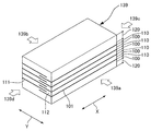
(해결 수단) 본 발명의 압전 소자는, 제1, 제2 시트(100, 110)를 적층한 적층체(139)이다.
제1 시트(100)의 제1 전극(101)은, 상기 적층체(139)의 제1 측면(139a)에 위치하는 제1 영역(161)과, 상기 제1 측면(139a)과 대향한 제2 측면(139b)을 향하는 제2 영역(162)을 갖고 있다.
제2 시트(110)의 상기 제2 전극(111)은, 상기 제2 측면(139b)에 위치하는 제3 영역(163)과, 상기 제1 측면(139a)을 향하는 제4 영역(164)을 갖고 있다.
상기 적층체(139)는 복수의 홈(144)으로 나뉘어져 있으며, 상기 제4 영역(164)과 상기 제1 영역(161)이 대향한 제5 영역(125a)을 갖는 제1 구동 유닛(U1, U5)과, 상기 제2 영역(162)과 상기 제3 영역(163)이 대향한 제6 영역(125b)을 갖는 제2 구동 유닛(U3, U7)이, 상기 홈(144)을 사이에 두고 위치하고 있다.
제1 구동 유닛(U1, U5)의 영역의 중심을 연결하는 직선(L1, L2)과, 제2 구동 유닛(U3, U7)의 영역의 중심을 연결하는 직선(L2)이 존재하고 있다.
Description
도 2는 제1, 제2, 제3 시트의 적층 상태를 나타내는 주요부의 분해도
도 3은 제1, 제2, 제3의 시트를 적층한 적층체의 사시도
도 4는 (a) 도전막을 형성한 적층체를 정면에서 본 사시도와 (b) 적층체의 배면도 및 (c) 일부를 삭제한 적층체의 정면에서 본 사시도
도 5는 도전막을 형성한 적층체의 다른 구체예의 사시도
도 6은 적층체에 복수의 홈을 형성한 압전 소자의 사시도와 (b) 그 정면도
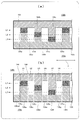
도 7은 도 6(b)에 있어서의 g-gg선을 따른 단면도와 (b) h-hh선을 따른 단면도
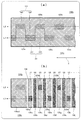
도 8은 (a) 적층 후에 홈(144)을 형성하기 전 상태를 상면으로부터 본 전극의 적층 상태를 나타내는 적층체의 투시도와 (b) 홈(144)을 형성한 후의 압전 소자를 상면으로부터 본 전극의 적층 상태를 나타내는 투시도
도 9는 실시형태 1의 상면에 다른 홈(151)을 더 형성한 압전 소자의 사시도
도 10은 (a) 본 발명의 실시형태 2의 압전 소자에 사용하는 제1 시트의 사시도와 (b) 제2 시트의 사시도
도 11은 실시형태 2에 있어서 (a) 적층 후에 홈(144)을 형성하기 전 상태를 상면으로부터 본 전극의 적층 상태를 나타내는 적층체의 투시도와 (b) 홈(144)을 형성한 후의 압전 소자를 상면으로부터 본 전극의 적층 상태를 나타내는 투시도
도 12는 (a) 본 발명의 실시형태 3의 압전 소자에 사용하는 제1 시트의 사시도와 (b) 제2 시트의 사시도
도 13은 실시형태 3에 있어서 (a) 적층 후에 홈(144)을 형성하기 전 상태를 상면으로부터 본 전극의 적층 상태를 나타내는 적층체의 투시도와 (b) 홈(144)을 형성한 후의 압전 소자를 상면으로부터 본 전극의 적층 상태를 나타내는 투시도
도 14는 (a) 본 발명의 실시형태 4의 압전 소자에 사용하는 제1 시트의 사시도와 (b) 제2 시트의 사시도
도 15는 (a) 적층 후에 홈(144)을 형성하기 전 상태를 상면으로부터 본 전극의 적층 상태를 나타내는 적층체의 투시도와 (b) 홈(144)을 형성한 후의 압전 소자를 상면으로부터 본 전극의 적층 상태를 나타내는 투시도
도 16은 (a) 본 발명의 실시형태 5의 압전 소자에 사용하는 제1 시트의 사시도와 (b) 제2 시트의 사시도
도 17은 (a) 적층 후에 홈(144)을 형성하기 전 상태를 상면으로부터 본 전극의 적층 상태를 나타내는 적층체의 투시도와 (b) 홈(144)을 형성한 후의 압전 소자를 상면으로부터 본 전극의 적층 상태를 나타내는 투시도
도 18은 상기 각 실시형태의 압전 소자를 사용한 (a) 잉크젯 인쇄 장치의 정면도와 (b) 평면도 및 (c) 라인 헤드(50)의 하면을 나타내는 사시도
도 19는 종래의 압전 소자를 이용한 잉크젯 헤드의 사시도
도 20은 종래의 압전 소자를 이용한 잉크젯 헤드의 단면도
도 21은 종래의 압전 소자를 이용한 잉크젯 헤드의 사시도
도 22는 압전 소자로의 인가 전압의 방향과 신축하는 방향을 설명하는 도면
101:제1 전극
102:제1 비전극 영역
110:제2 시트
111:제2 전극
112:제2 비전극 영역
120:제3 시트
125a:제5 영역
125b:제6 영역
125c:제7 영역
139:적층체
139a:제1 측면
139b:제2 측면
139c:제3 측면
139d:제4 측면
139e:하면측
139f:상면측
140:압전 소자
144, 151:홈
161:제1 영역
162, 162a, 162b, 162c:제2 영역
163:제3 영역
164, 164a, 164b:제4 영역
U1, U2, U3, U4, …:유닛
L1, L2, L3:중심선
Claims (11)
- 압전체인 제1 시트와 압전체인 제2 시트를 적층한 적층체로 이루어지는 압전 소자에 있어서,
상기 적층체의 상면에서부터 하면의 도중까지 달하는 복수의 홈으로 나뉜 복수의 유닛과,
상기 적층체의 표면에 형성된 도전막과,
상기 제1 시트의 표면의 적어도 2변의 단부까지 형성된 제1 전극과,
상기 제2 시트의 표면의 적어도 2변의 단부까지 형성된 제2 전극을 갖는 압전 소자이며,
상기 제1 전극은, 상기 적층체의 제1 측면에 위치하는 제1 영역의 기단부와, 상기 제1 측면과 대향한 상기 적층체의 제2 측면을 향하는 제2 영역의 선단부를 갖고,
상기 제2 전극은, 상기 제2 측면에 위치하는 제3 영역의 기단부와, 상기 제1 측면을 향하는 제4 영역의 선단부를 갖고,
상기 도전막은, 상기 제2 측면의 상기 제2 전극과 상기 제1 측면의 제1 전극의 일부를 전기적으로 연결하는 도전성 막이며,
상기 복수의 유닛은, 상기 홈을 사이에 두고 위치하고 있는, 상기 제4 영역과 상기 제1 영역이 대향한 제5 영역을 가진 제1 구동 유닛과, 상기 제2 영역과 상기 제3 영역이 대향한 제6 영역을 가진 제2 구동 유닛을 갖고,
상기 적층 방향으로부터 본 경우에, 상기 제1 구동 유닛의 영역의 중심과, 상기 제2 구동 유닛의 영역의 중심을 연결하는 직선이 복수 존재하는, 압전 소자. - 청구항 1에 있어서,
상기 제1 전극과 상기 제2 전극의 형상이 상이한, 압전 소자. - 청구항 1에 있어서,
상기 제1 시트와 상기 제2 시트가 사각형인, 압전 소자. - 청구항 1에 있어서,
상기 제5 영역과 상기 제6 영역은 상기 적층체의 두께 방향으로 대향하지 않는, 압전 소자. - 청구항 1에 있어서,
상기 제1 시트는,
4변 중 3변까지 상기 제1 전극이 형성되고, 남은 1변에는 전극이 형성되어 있지 않은 제1 비전극 영역이 위치하고,
상기 제2 시트는,
4변 중 3변까지 상기 제2 전극이 형성되고, 남은 1변에는, 전극이 형성되어 있지 않은 제2 비전극 영역이 위치하는, 압전 소자. - 청구항 1에 있어서,
상기 제5 영역을 포함하는 상기 제1 구동 유닛과, 상기 제6 영역을 포함하는 상기 제2 구동 유닛 사이에, 상기 제5 영역과 상기 제6 영역의 양방을 포함하는 중간 유닛이 위치하는, 압전 소자. - 청구항 1에 있어서,
상기 제5 영역을 포함하는 제1 구동 유닛과, 상기 제6 영역을 포함하는 제2 구동 유닛 사이에,
상기 제5 영역과 상기 제6 영역 중 한쪽만을 포함하는 중간 유닛이 위치하는, 압전 소자. - 청구항 1에 있어서,
상기 제2 영역은,
상기 제1 영역으로부터 상기 제2 측면을 향하는 길이가 상이한 복수의 전극으로 구성되고,
상기 제4 영역은, 상기 제3 영역으로부터 상기 제1 측면을 향하는 길이가 상이한 복수의 전극으로 구성된, 압전 소자. - 청구항 1에 기재된 압전 소자를 이용하여 잉크를 피도포물에 도포하는, 잉크젯 헤드.
- 청구항 9에 기재된 상기 잉크젯 헤드를 이용하여 잉크를 피도포물에 도포하는, 잉크젯 장치.
- 청구항 1에 기재된 압전 소자를 이용하여 잉크를 피도포물에 도포하는, 도포 방법.
Applications Claiming Priority (2)
| Application Number | Priority Date | Filing Date | Title |
|---|---|---|---|
| JP2013112600A JP6123073B2 (ja) | 2013-05-29 | 2013-05-29 | 圧電素子及びそれを用いたインクジェット装置とその方法 |
| JPJP-P-2013-112600 | 2013-05-29 |
Publications (1)
| Publication Number | Publication Date |
|---|---|
| KR20140140499A true KR20140140499A (ko) | 2014-12-09 |
Family
ID=51984629
Family Applications (1)
| Application Number | Title | Priority Date | Filing Date |
|---|---|---|---|
| KR1020140063085A Ceased KR20140140499A (ko) | 2013-05-29 | 2014-05-26 | 압전 소자 및 그것을 이용한 잉크젯 헤드와 도포 방법 |
Country Status (3)
| Country | Link |
|---|---|
| US (1) | US9033473B2 (ko) |
| JP (1) | JP6123073B2 (ko) |
| KR (1) | KR20140140499A (ko) |
Families Citing this family (2)
| Publication number | Priority date | Publication date | Assignee | Title |
|---|---|---|---|---|
| CA3131707A1 (en) * | 2020-09-24 | 2022-03-24 | First Quality Tissue, Llc | Systems and methods for application of surface chemistry to bath tissue, facial tissue, and paper towel |
| CN119764291B (zh) * | 2025-03-06 | 2025-06-17 | 嘉善复旦研究院 | 半导体器件、半导体封装和半导体封装方法 |
Family Cites Families (7)
| Publication number | Priority date | Publication date | Assignee | Title |
|---|---|---|---|---|
| WO1996000151A1 (en) * | 1994-06-23 | 1996-01-04 | Citizen Watch Co., Ltd. | Piezoelectric actuator for ink jet head and method of manufacturing same |
| JPH09174830A (ja) | 1995-12-22 | 1997-07-08 | Nec Corp | インクジェット記録ヘッド |
| JP3956607B2 (ja) * | 2000-10-26 | 2007-08-08 | ブラザー工業株式会社 | 圧電式インクジェットプリンタヘッド及び圧電式インクジェットプリンタヘッドの製造方法 |
| JP3852309B2 (ja) * | 2001-07-24 | 2006-11-29 | 株式会社村田製作所 | 積層型圧電体素子及びその製造方法、並びに、圧電アクチュエータ |
| JP4145760B2 (ja) * | 2002-10-03 | 2008-09-03 | セイコーエプソン株式会社 | 圧電アクチュエータユニット及びその製造方法 |
| JP3925650B2 (ja) * | 2003-03-06 | 2007-06-06 | ブラザー工業株式会社 | インクジェットプリンタヘッド |
| JP5359129B2 (ja) * | 2008-09-01 | 2013-12-04 | 株式会社リコー | 圧電アクチュエータ、液体吐出ヘッド及び画像形成装置 |
-
2013
- 2013-05-29 JP JP2013112600A patent/JP6123073B2/ja active Active
-
2014
- 2014-05-26 KR KR1020140063085A patent/KR20140140499A/ko not_active Ceased
- 2014-05-29 US US14/290,381 patent/US9033473B2/en not_active Expired - Fee Related
Also Published As
| Publication number | Publication date |
|---|---|
| US9033473B2 (en) | 2015-05-19 |
| JP6123073B2 (ja) | 2017-05-10 |
| US20140354737A1 (en) | 2014-12-04 |
| JP2014232789A (ja) | 2014-12-11 |
Similar Documents
| Publication | Publication Date | Title |
|---|---|---|
| JP6130611B1 (ja) | 流路部材、液体吐出ヘッドおよび記録装置 | |
| JP5752906B2 (ja) | 液体噴射ヘッドの製造方法 | |
| US9466779B2 (en) | Piezoelectric actuator and method of manufacturing piezoelectric actuator | |
| JP5428656B2 (ja) | 液滴吐出装置 | |
| JP4770393B2 (ja) | 液体移送装置 | |
| US6536880B2 (en) | Piezoelectric ink jet printer head and method for manufacturing same | |
| JP3873729B2 (ja) | 圧電アクチュエータおよび液滴噴射装置並びにそれらの製造方法 | |
| JP5402476B2 (ja) | 液滴吐出装置 | |
| JP2010125765A (ja) | 液体吐出ヘッド | |
| CN106457833B (zh) | 液体喷出头用的流路构件及液体喷出头、记录装置 | |
| KR20140140499A (ko) | 압전 소자 및 그것을 이용한 잉크젯 헤드와 도포 방법 | |
| JP5392187B2 (ja) | 圧電アクチュエータ及び液体噴射装置 | |
| JP2011167875A (ja) | 圧電アクチュエータ及び圧電アクチュエータの製造方法 | |
| JP6616146B2 (ja) | 液体吐出ヘッド用の流路部材、ならびにそれを用いた、液体吐出ヘッドおよびに記録装置 | |
| JP2016043616A (ja) | 圧電アクチュエータ基板、それを用いた液体吐出ヘッドおよび記録装置 | |
| JP4193890B2 (ja) | インクジェットヘッド | |
| JP6127993B2 (ja) | 圧電アクチュエータ | |
| JP2015085621A (ja) | 液体吐出ヘッド、およびそれを用いた記録装置 | |
| JP5076512B2 (ja) | 液滴吐出装置 | |
| JP2000117971A (ja) | 積層圧電型駆動体及びその製造方法並びにインクジェットヘッド | |
| JP4655060B2 (ja) | 液体吐出ヘッドの製造方法 | |
| JP2015085623A (ja) | 液体吐出ヘッド、およびそれを用いた記録装置 | |
| JP6181531B2 (ja) | 液体吐出ヘッド、およびそれを用いた記録装置 | |
| JP2016137660A (ja) | 液体吐出ヘッド、およびそれを用いた記録装置 | |
| JP2011054628A (ja) | 圧電アクチュエータの製造方法 |
Legal Events
| Date | Code | Title | Description |
|---|---|---|---|
| PA0109 | Patent application |
Patent event code: PA01091R01D Comment text: Patent Application Patent event date: 20140526 |
|
| PG1501 | Laying open of application | ||
| N231 | Notification of change of applicant | ||
| PN2301 | Change of applicant |
Patent event date: 20151215 Comment text: Notification of Change of Applicant Patent event code: PN23011R01D |
|
| A201 | Request for examination | ||
| PA0201 | Request for examination |
Patent event code: PA02012R01D Patent event date: 20181221 Comment text: Request for Examination of Application Patent event code: PA02011R01I Patent event date: 20140526 Comment text: Patent Application |
|
| E902 | Notification of reason for refusal | ||
| PE0902 | Notice of grounds for rejection |
Comment text: Notification of reason for refusal Patent event date: 20200515 Patent event code: PE09021S01D |
|
| E601 | Decision to refuse application | ||
| PE0601 | Decision on rejection of patent |
Patent event date: 20200828 Comment text: Decision to Refuse Application Patent event code: PE06012S01D Patent event date: 20200515 Comment text: Notification of reason for refusal Patent event code: PE06011S01I |