KR20160021402A - Drive assembly - Google Patents
Drive assembly Download PDFInfo
- Publication number
- KR20160021402A KR20160021402A KR1020140106303A KR20140106303A KR20160021402A KR 20160021402 A KR20160021402 A KR 20160021402A KR 1020140106303 A KR1020140106303 A KR 1020140106303A KR 20140106303 A KR20140106303 A KR 20140106303A KR 20160021402 A KR20160021402 A KR 20160021402A
- Authority
- KR
- South Korea
- Prior art keywords
- piston
- pipe
- speed
- control unit
- control
- Prior art date
- Legal status (The legal status is an assumption and is not a legal conclusion. Google has not performed a legal analysis and makes no representation as to the accuracy of the status listed.)
- Granted
Links
Images





Classifications
-
- H—ELECTRICITY
- H10—SEMICONDUCTOR DEVICES; ELECTRIC SOLID-STATE DEVICES NOT OTHERWISE PROVIDED FOR
- H10P—GENERIC PROCESSES OR APPARATUS FOR THE MANUFACTURE OR TREATMENT OF DEVICES COVERED BY CLASS H10
- H10P72/00—Handling or holding of wafers, substrates or devices during manufacture or treatment thereof
- H10P72/30—Handling or holding of wafers, substrates or devices during manufacture or treatment thereof for conveying, e.g. between different workstations
- H10P72/32—Handling or holding of wafers, substrates or devices during manufacture or treatment thereof for conveying, e.g. between different workstations between different workstations
- H10P72/3206—Handling or holding of wafers, substrates or devices during manufacture or treatment thereof for conveying, e.g. between different workstations between different workstations the substrate being handled substantially vertically
Landscapes
- Cleaning Or Drying Semiconductors (AREA)
Abstract
본 발명은 구동 어셈블리에 관한 것이다. 본 발명의 일 실시 예에 따른 구동 어셈블리는 피스톤; 상기 피스톤을 이동 가능하게 수용하고, 상기 피스톤의 구동을 위한 유체가 공급되는 배관들에 연결되는 실린더; 상기 실린더의 내부에 위치되는 센서들; 및 상기 배관을 유동하는 유체를 통해 상기 피스톤의 속력을 제어하되, 상기 센서들에 의해 감지된 신호를 바탕으로 계측된 상기 피스톤의 계측 속력을 설정 속력과 비교하는 방식으로 상기 피스톤의 속력을 자동으로 조절하는 배관 제어 유닛을 포함한다.The present invention relates to a drive assembly. A driving assembly according to an embodiment of the present invention includes a piston; A cylinder movably receiving the piston and connected to pipes through which fluid for driving the piston is supplied; Sensors positioned within the cylinder; And controlling the speed of the piston through the fluid flowing through the pipe such that the speed of the piston is automatically determined by comparing the measurement speed of the piston measured based on the signal sensed by the sensors with the set speed And a pipe control unit for controlling the pipe.
Description
본 발명은 구동 어셈블리에 관한 것이다.The present invention relates to a drive assembly.
반도체 소자를 제조하기 위해서는 기판에 세정, 증착, 포토 리소그래피, 에칭, 그리고 이온주입 등과 같은 다양한 공정이 수행된다. 위의 각 공정들은 서로 상이한 구성을 갖는 공정 챔버에서 수행될 수 있다. 그리고 기판은 로봇 또는 레일 등을 포함하는 이송 챔버에 의해 공정 챔버와 공정 챔버 사이로 이송될 수 있다.Various processes such as cleaning, deposition, photolithography, etching, and ion implantation are performed on a substrate to manufacture a semiconductor device. Each of the above processes can be performed in a process chamber having a different configuration from each other. And the substrate may be transferred between the process chamber and the process chamber by a transfer chamber including a robot or a rail or the like.
위와 같은 공정 챔버 또는 이송 챔버의 구동 요소는 동력을 제공하는 구동부재에 의해 동작될 수 있다. 이와 같은 구동부재는 실린더 및 피스톤 구조를 가질 수 있다.The driving element of such a process chamber or transfer chamber may be operated by a driving member that provides power. Such a drive member may have a cylinder and piston structure.
본 발명은 효율적으로 동작하는 피스톤을 갖는 구동 어셈블리를 제공하기 위한 것이다.SUMMARY OF THE INVENTION The present invention is directed to providing a drive assembly with a piston that operates efficiently.
본 발명의 일 측면에 따르면, 피스톤; 상기 피스톤을 이동 가능하게 수용하고, 상기 피스톤의 구동을 위한 유체가 공급되는 배관들에 연결되는 실린더; 상기 실린더의 내부에 위치되는 센서들; 및 상기 배관을 유동하는 유체를 통해 상기 피스톤의 속력을 제어하되, 상기 센서들에 의해 감지된 신호를 바탕으로 계측된 상기 피스톤의 계측 속력을 설정 속력과 비교하는 방식으로 상기 피스톤의 속력을 자동으로 조절하는 배관 제어 유닛을 포함하는 구동 어셈블리가 제공될 수 있다.According to an aspect of the present invention, there is provided a piston comprising: a piston; A cylinder movably receiving the piston and connected to pipes through which fluid for driving the piston is supplied; Sensors positioned within the cylinder; And controlling the speed of the piston through the fluid flowing through the pipe such that the speed of the piston is automatically determined by comparing the measurement speed of the piston measured based on the signal sensed by the sensors with the set speed A drive assembly may be provided that includes a piping control unit for regulating.
또한, 상기 센서들은, 상기 피스톤이 이동하는 방향의 일측에 위치되는 제 1 센서; 및 상기 피스톤이 이동하는 방향의 타측에 위치되는 제 2 센서를 포함할 수 있다.Further, the sensors may include: a first sensor positioned at one side in a direction in which the piston moves; And a second sensor positioned on the other side of the direction in which the piston moves.
또한, 상기 배관 제어 유닛은 상기 제 1 센서와 상기 제 2 센서가 송신하는 신호의 시간차를 이용해 상기 계측 속력을 산출할 수 있다.Further, the piping control unit can calculate the measurement speed using the time difference between the signals transmitted by the first sensor and the second sensor.
또한, 상기 배관 제어 유닛은, 상기 배관들을 유동하는 유체를 제어하는 배관 제어 모듈; 및 제어 값을 통해 상기 배관 제어 모듈의 동작을 조절하는 모듈 제어부를 포함할 수 있다.In addition, the piping control unit may include: a piping control module for controlling a fluid flowing through the piping; And a module control unit for controlling the operation of the piping control module through a control value.
또한, 상기 배관 제어 모듈은 피에조 에추에이터를 포함하여 구성될 수 있다.In addition, the pipe control module may include a piezo actuator.
또한, 상기 제어 값은 전압 값으로 제공될 수 있다.Also, the control value may be provided as a voltage value.
또한 상기 모듈 제어부는 상기 제어 값을 초기 제어 값으로 설정하여 상기 피스톤을 구동한 후, 산출된 상기 계측 속력에 따라 상기 제어 값을 증가 또는 감소 시키는 작업을 1회 이상 수행하여 상기 피스톤의 속력을 자동으로 조절할 수 있다.Further, the module control unit sets the control value as an initial control value, drives the piston, and then performs an operation of increasing or decreasing the control value in accordance with the calculated measurement speed at least once to automatically speed the piston .
본 발명의 일 실시 예에 의하면, 동작하는 피스톤을 갖는 구동 어셈블리가 제공될 수 있다.According to one embodiment of the present invention, a drive assembly having an operating piston can be provided.
도 1은 본 발명의 실시 예에 따른 기판 처리 장치를 보여주는 평면도이다.
도 2는 본 발명의 일 실시 예에 따른 구동 어셈블리를 나타내는 도면이다.
도 3은 배관 제어 유닛을 나타내는 도면이다.
도 4는 배관 제어 모듈의 구체적 구성을 도시한 도면이다.
도 5는 피스톤이 실린더의 하부에서 상부로 이동할 때를 나타내는 도면이다.
도 6은 피스톤의 속력이 조절되는 과정을 나타내는 플로우 차트이다.
도 7은 피스톤이 실린더의 상부에서 하부로 이동할 때를 나타내는 도면이다.
도 8은 다른 실시 예에 따라 피스톤의 속력이 조절되는 과정을 나타내는 플로우 차트이다.1 is a plan view showing a substrate processing apparatus according to an embodiment of the present invention.
2 illustrates a drive assembly according to an embodiment of the present invention.
3 is a view showing a piping control unit.
4 is a diagram showing a specific configuration of the piping control module.
5 is a view showing the piston moving from the lower part to the upper part of the cylinder.
6 is a flowchart showing a process of controlling the speed of the piston.
7 is a view showing when the piston moves from the upper part to the lower part of the cylinder.
8 is a flowchart showing a process of controlling the speed of the piston according to another embodiment.
이하, 본 발명의 실시 예를 첨부된 도면들을 참조하여 더욱 상세하게 설명한다. 본 발명의 실시 예는 여러 가지 형태로 변형할 수 있으며, 본 발명의 범위가 아래의 실시 예들로 한정되는 것으로 해석되어서는 안 된다. 본 실시 예는 당업계에서 평균적인 지식을 가진 자에게 본 발명을 더욱 완전하게 설명하기 위해 제공되는 것이다. 따라서 도면에서의 요소의 형상은 보다 명확한 설명을 강조하기 위해 과장되었다.Hereinafter, embodiments of the present invention will be described in detail with reference to the accompanying drawings. The embodiments of the present invention can be modified in various forms, and the scope of the present invention should not be construed as being limited to the following embodiments. This embodiment is provided to more fully describe the present invention to those skilled in the art. Thus, the shape of the elements in the figures has been exaggerated to emphasize a clearer description.
도 1은 본 발명의 실시 예에 따른 기판 처리 장치를 보여주는 평면도이다. 1 is a plan view showing a substrate processing apparatus according to an embodiment of the present invention.
도 1을 참조하면, 기판 처리 장치(1)는 인덱스 모듈(10)과 공정 처리 모듈(20)을 가진다. 인덱스 모듈(10)은 로드 포트(120) 및 이송 프레임(140)을 가진다. 로드 포트(120), 이송 프레임(140), 그리고 공정 처리 모듈(20)은 순차적으로 일렬로 배열된다. 이하, 로드 포트(120), 이송 프레임(140), 그리고 공정 처리 모듈(20)이 배열된 방향을 제 1 방향(12)이라 하고, 상부에서 바라볼 때, 제 1 방향(12)과 수직한 방향을 제 2 방향(14)이라 하며, 제 1 방향(12)과 제 2 방향(14)을 포함한 평면에 수직인 방향을 제 3 방향(16)이라 한다. Referring to FIG. 1, the
로드 포트(140)에는 기판(W)이 수납된 캐리어(130)가 위치된다. 로드 포트(120)는 복수 개가 제공되며 이들은 제 2 방향(14)을 따라 일렬로 배치된다. 로드 포트(120)의 개수는 공정 처리 모듈(20)의 공정효율 및 풋 프린트조건 등에 따라 증가하거나 감소할 수도 있다. 캐리어(130)에는 기판(W)들을 지면에 대해 수평하게 배치한 상태로 수납하기 위한 다수의 슬롯(미도시)이 형성된다. 캐리어(130)로는 전면개방일체형포드(Front Opening Unifed Pod, FOUP)가 사용될 수 있다. In the
공정 처리 모듈(20)은 버퍼 유닛(220), 이송 챔버(240), 그리고 공정 챔버(260)를 가진다. 이송 챔버(240)는 그 길이 방향이 제 1 방향(12)과 평행하게 배치된다. 이송 챔버(240)의 양측에는 각각 공정 챔버(260)들이 배치된다. 이송 챔버(240)의 일측 및 타측에서 공정 챔버(260)들은 이송 챔버(240)를 기준으로 대칭되도록 제공된다. 이송 챔버(240)의 일측에는 복수 개의 공정 챔버(260)들이 제공된다. 공정 챔버(260)들 중 일부는 이송 챔버(240)의 길이 방향을 따라 배치된다. 또한, 공정 챔버(260)들 중 일부는 서로 적층되게 배치된다. 즉, 이송 챔버(240)의 일측에는 공정 챔버(260)들이 A X B의 배열로 배치될 수 있다. 여기서 A는 제 1 방향(12)을 따라 일렬로 제공된 공정 챔버(260)의 수이고, B는 제 3 방향(16)을 따라 일렬로 제공된 공정 챔버(260)의 수이다. 이송 챔버(240)의 일측에 공정 챔버(260)가 4개 또는 6개 제공되는 경우, 공정 챔버(260)들은 2 X 2 또는 3 X 2의 배열로 배치될 수 있다. 공정 챔버(260)의 개수는 증가하거나 감소할 수도 있다. 상술한 바와 달리, 공정 챔버(260)는 이송 챔버(240)의 일 측에만 제공될 수 있다. 또한, 공정 챔버(260)는 이송 챔버(240)의 일측 및 양측에 단층으로 제공될 수 있다.The
버퍼 유닛(220)은 이송 프레임(140)과 이송 챔버(240) 사이에 배치된다. 버퍼 유닛(220)은 이송 챔버(240)와 이송 프레임(140) 간에 기판(W)이 반송되기 전에 기판(W)이 머무르는 공간을 제공한다. 버퍼 유닛(220)의 내부에는 기판(W)이 놓이는 슬롯(미도시)이 제공된다. 슬롯(미도시)들은 서로 간에 제 3 방향(16)을 따라 이격되도록 복수 개가 제공된다. 버퍼 유닛(220)은 이송 프레임(140)과 마주보는 면 및 이송 챔버(240)와 마주보는 면이 개방된다. The
이송 프레임(140)은 로드 포트(120)에 안착된 캐리어(130)와 버퍼 유닛(220) 간에 기판(W)을 반송한다. 이송 프레임(140)에는 인덱스 레일(142)과 인덱스로봇(144)이 제공된다. 인덱스 레일(142)은 그 길이 방향이 제 2 방향(14)과 나란하게 제공된다. 인덱스로봇(144)은 인덱스 레일(142) 상에 설치되며, 인덱스 레일(142)을 따라 제 2 방향(14)으로 직선 이동된다. 인덱스로봇(144)은 베이스(144a), 몸체(144b), 그리고 인덱스암(144c)을 가진다. 베이스(144a)는 인덱스 레일(142)을 따라 이동 가능하도록 설치된다. 몸체(144b)는 베이스(144a)에 결합된다. 몸체(144b)는 베이스(144a) 상에서 제 3 방향(16)을 따라 이동 가능하도록 제공된다. 또한, 몸체(144b)는 베이스(144a) 상에서 회전 가능하도록 제공된다. 인덱스암(144c)은 몸체(144b)에 결합되고, 몸체(144b)에 대해 전진 및 후진 이동 가능하도록 제공된다. 인덱스암(144c)은 복수 개 제공되어 각각 개별 구동되도록 제공된다. 인덱스암(144c)들은 제 3 방향(16)을 따라 서로 이격 된 상태로 적층되게 배치된다. 인덱스암(144c)들 중 일부는 공정 처리 모듈(20)에서 캐리어(130)로 기판(W)을 반송할 때 사용되고, 이의 다른 일부는 캐리어(130)에서 공정 처리 모듈(20)로 기판(W)을 반송할 때 사용될 수 있다. 이는 인덱스로봇(144)이 기판(W)을 반입 및 반출하는 과정에서 공정 처리 전의 기판(W)으로부터 발생된 파티클이 공정 처리 후의 기판(W)에 부착되는 것을 방지할 수 있다. The
이송 챔버(240)는 버퍼 유닛(220)과 공정 챔버(260) 간에, 그리고 공정 챔버(260)들 간에 기판(W)을 반송한다. 이송 챔버(240)에는 가이드 레일(242)과 메인 로봇(244)이 제공된다. 가이드 레일(242)은 그 길이 방향이 제 1 방향(12)과 나란하도록 배치된다. 메인 로봇(244)은 가이드 레일(242) 상에 설치되고, 가이드 레일(242) 상에서 제 1 방향(12)을 따라 직선 이동된다. 메인 로봇(244)은 베이스(244a), 몸체(244b), 그리고 메인 암(244c)을 가진다. 베이스(244a)는 가이드 레일(242)을 따라 이동 가능하도록 설치된다. 몸체(244b)는 베이스(244a)에 결합된다. 몸체(244b)는 베이스(244a) 상에서 제 3 방향(16)을 따라 이동 가능하도록 제공된다. 또한, 몸체(244b)는 베이스(244a) 상에서 회전 가능하도록 제공된다. 메인 암(244c)은 몸체(244b)에 결합되고, 이는 몸체(244b)에 대해 전진 및 후진 이동 가능하도록 제공된다. 메인 암(244c)은 복수 개 제공되어 각각 개별 구동되도록 제공된다. 메인 암(244c)들은 제 3 방향(16)을 따라 서로 이격된 상태로 적층되게 배치된다. The
공정 챔버(260)는 기판(W)에 대해 처리 공정을 수행한다. 공정 챔버(260)에서 수행되는 공정은 기판에 대해 세정, 증착, 포토 리소그래피, 에칭, 또는 이온주입 공정일 수 있다.The
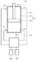
도 2는 본 발명의 일 실시 예에 따른 구동 어셈블리를 나타내는 도면이다.2 illustrates a drive assembly according to an embodiment of the present invention.
도 2를 참조하면, 구동 어셈블리(800)는 기판 처리 장치(1)의 일 구성이 동작하는 동력을 제공한다. 구동 어셈블리(800)는 구동 부재(810) 및 배관 제어 유닛(830)을 포함한다.Referring to FIG. 2, the
구동 부재(810)는 기판 처리 장치(1)의 일 구성이 동작하는 동력을 제공한다. 예를 들어, 구동 부재(810)는 인덱스로봇(144) 또는 메인 로봇(244)에 연결되어, 인덱스로봇(144) 또는 메인 로봇(244)이 구동하는 동력을 제공할 수 있다. 또한, 구동 부재(810)는 버퍼 유닛(220), 이송 챔버(240) 또는 공정 챔버(260)에 제공되어, 위 유닛들의 구성이 동작하는 동력을 제공할 수 있다.The driving
구동 부재(810)는 실린더(811) 및 피스톤(812)을 포함한다. 실린더(811)는 내부에는 피스톤(812)이 왕복 운동할 수 있는 공간이 형성된다. 피스톤(812)의 일면에는 구동 축(813)이 연결된다. 구동 축(813)은 피스톤(812)의 이동으로 발생된 동력을 기판 처리 장치(1)의 구성으로 전달한다. 이하 실린더(811)에서 구동 축(813)이 외부로 연결되는 일 측은 실린더(811)의 상부, 그 반대쪽 일 측을 실린더(811)의 하부라 한다.The driving
실린더(811)에는 제 1 홀(814) 및 제 2 홀(815)이 형성된다. 제 1 홀(814)은 실린더(811)의 상부 측벽 또는 상벽에 형성되고, 제 2 홀(815)은 실린더(811)의 하부 측벽 또는 하벽에 형성된다. 피스톤(812)은 제 1 홀(814) 또는 제 2 홀(815)로 공급되는 기체에 의해 제 1 홀(814)과 제 2 홀(815) 사이를 이동할 수 있다.A
실린더(811)의 측면에는 센서들(816, 817)이 제공된다. 센서들(816, 817)은 실린더(811)의 상부에 위치되는 제 1 센서(816) 및 실린더(811)의 하부에 위치되는 제 2 센서(817)를 포함한다. 제 1 센서(816) 및 제 2 센서(817)는 각각 피스톤(812)이 실린더(811)의 상부와 실린더(811)의 하부에 위치되었는지 여부를 감지할 수 있다.
배관 제어 유닛(830)은 구동 부재(810)와 연결되어, 구동 부재(810)의 동작을 조절한다. 구체적으로, 제 1 홀(814) 및 제 2 홀(815)은 각각 제 1 배관(821) 및 제 2 배관(822)을 통해 배관 제어 유닛(830)에 연결된다. 또한, 배관 제어 유닛(830)은 유체 공급원(850)과 연결된다. 유체 공급원(850)은 제 1 배관(821) 및 제 2 배관(822)으로 공급될 유체를 저장한다. 배관 제어 유닛(830)은 제 1 홀(814)을 통해 실린더(811)로 공급되거나 제 1 홀(814)을 통해 실린더(811)에서 배출되는 유체의 양을 조절할 수 있다. 또한, 배관 제어 유닛(830)은 제 2 홀(815)을 통해 실린더(811)로 공급 되거나, 제 2 홀(815)을 통해 실린더(811)에서 배출되는 유체의 양을 조절할 수 있다.The
배관 제어 유닛(830)은 제 1 센서(816) 및 제 2 센서(817)로부터 감지된 신호를 입력 받는다. 또한, 배관 제어 유닛(830)은 제어 부재(860)와 연결될 수 있다. 제어 부재(860)는 구동 부재(810)의 동작과 관련된 정보를 저장할 수 있다. 예를 들어, 제어 부재(860)는 피스톤(812)이 실린더(811)의 상부에서 하부로 이동하거나, 실린더(811)의 하부에서 상부로 이동할 때의 설정 속력을 저장하고 있을 수 있다. 또한, 제어 부재(860)는 피스톤(812)의 동작 종료와 다음 동작 개시 사이의 시간 간격에 관한 정보를 저장하고 있을 수 있다. 사용자는 제어 부재(860)에 저장된 위 정보들을 변경할 수 있다. 제어 부재(860)는 배관 제어 유닛(830)과 무선 또는 유선으로 연결되어, 구동 부재(810)의 동작과 관련된 정보를 배관 제어 유닛(830)에 제공한다. 또한, 제어 부재(860)는 기판 처리 장치(1)의 각 구성의 제어에 관한 정보들을 저장하고 있을 수 있다. 또한, 제어 부재(860)는 위 정보들을 이용하여 기판 처리 장치(1)의 각 구성의 동작을 제어 할 수 있다. 배관 제어 유닛(830)은 제 1 센서(816) 및 제 2 센서(817)와 제어 부재(860)에서 제공된 정보를 통해, 제 1 배관(821) 또는 제 2 배관(822)으로 공급되거나, 제 2 배관(822) 또는 제 2 배관(822)에서 배출되는 유체의 양을 조절할 수 있다.The
도 3은 배관 제어 유닛을 나타내는 도면이다.3 is a view showing a piping control unit.
도 2 및 도 3을 참조하면, 배관 제어 유닛(830)은 피스톤(812)의 이동 속력을 감지할 수 있다. Referring to FIGS. 2 and 3, the
배관 제어 유닛(830)은 모듈 제어부(831) 및 배관 제어 모듈(832)을 포함한다.The
모듈 제어부(831)는 센서들(816, 817) 및 배관 제어 모듈(832)과 연결된다. 모듈 제어부(831)는 센서들(816, 817)로부터 입력되는 신호 및 제어 부재(860)가 제공하는 정보를 통해 배관 제어 모듈(832)을 제어한다. 모듈 제어부(831)는 센서들(816, 817)로부터 입력되는 신호를 통해 피스톤(812)의 이동 속력을 산출할 수 있다. 피스톤(812)은 실린더(811) 하부의 일 위치에서 실린더(811) 상부의 일 위치로 이동할 수 있다. 또한, 피스톤(812)은 실린더(811) 상부의 일 위치에서 실린더(811) 하부의 일 위치로 이동할 수 있다. 제 1 센서(816) 및 제 2 센서(817)는 각각 실린더(811) 상부 및 실린더(811) 하부에 피스톤(812)이 위치되는지 여부에 따라 상이한 정보를 모듈 제어부(831)로 송신한다. 예를 들어, 제 1 센서(816) 및 제 2 센서(817)는 각각 실린더(811)의 상부 및 하부에 피스톤(812)이 위치되는 것으로 감지될 때, 설정 신호를 모듈 제어부(831)로 송신할 수 있다. 그리고, 제 1 센서(816) 및 제 2 센서(817)는 각각 피스톤(812)이 이동됨에 따라 실린더(811)의 상부 및 하부에 없을 때 신호를 송신하지 않을 수 있다. 따라서, 피스톤(812)이 실린더(811) 하부에서 상부로 이동하는 경우, 먼저 제 2 센서(817)에서 송신되는 신호가 변경된 후 제 1 센서(816)에서 송신되는 신호가 변경된다. 또한, 피스톤(812)이 실린더(811)의 상부에서 하부로 이동하는 경우, 먼저 제 1 센서(816)에서 송신되는 신호가 변경된 후 제 2 센서(817)에서 송신되는 신호가 변경된다. 모듈 제어부(831)는 이와 같이 센서들(816, 817)에서 송신되는 신호들 사이의 시간차를 이용해 피스톤(812)의 이동 속력을 산출할 수 있다. The
도 4는 배관 제어 모듈의 구체적 구성을 도시한 도면이다.4 is a diagram showing a specific configuration of the piping control module.
도 2 내지 도 4를 참조하면, 모듈 제어부(831)는 배관 제어 모듈(832)에 대한 조정을 수행한다.Referring to FIGS. 2 to 4, the
배관 제어 모듈(832)은 제 1 배관 제어 부재(832a) 및 제 2 배관 제어 부재(832b)를 포함한다.The
제 1 배관 제어 부재(832a)는 제 1 배관(821) 및 유체 공급원(850)에 각각 연결된다. 제 1 제관 제어 부재(860)는 유체 공급원(850)에서 제 1 배관(821)을 통해 실린더(811) 상부 공간으로 공급되는 유체를 조절할 수 있다. 또한, 제 1 배관 제어 부재(832a)는 실린더(811) 상부의 공간에서 제 1 배관(821)을 통해 외부로 배출되는 유체를 조절할 수 도 있다. 제 1 배관 제어 부재(832a)는 피에조 액추에이터를 포함하여 구성될 수 있다. 피에조 액추에이터는 모듈 제어부(831)의 신호에 대한 응답이 빠르게 제공되어, 구동 부재(810)의 구동성을 향상 시킬 수 있다.The first
제 2 배관 제어 부재(832b)는 제 2 배관(822) 및 유체 공급원(850)에 각각 연결된다. 제 2 배관 제어 부재(832b)는 유체 공급원(850)에서 제 2 배관(822)을 통해 실린더(811) 하부 공간으로 공급되는 유체를 조절할 수 있다. 또한, 제 2 배관 제어 부재(832b)는 실린더(811) 하부의 공간에서 제 2 배관(822)을 통해 외부로 배출되는 유체를 조절할 수 도 있다. 제 2 배관 제어 부재(832b)는 피에조 액추에이터를 포함하여 구성될 수 있다. 피에조 액추에이터는 모듈 제어부(831)의 신호에 대한 응답이 빠르게 제공되어, 구동 부재(810)의 구동성을 향상 시킬 수 있다.And the second
모듈 제어부(831)는 제 1 배관 제어 부재(832a) 및 제 2 배관 제어 부재(832b)에 연결되어 그 동작을 제어한다. 배관 제어 부재(832a, 832b)가 피에조 액추에이터를 포함하여 구성되는 경우, 모듈 제어부(831)는 배관 제어 부재(832a, 832b)로 인가되는 전압 값을 통해 배관 제어 부재(832a, 832b)를 제어할 수 있다. 예를 들어, 모듈 제어부(831)가 배관 제어 부재(832a, 832b)로 인가는 전압이 증가되면 배관(821, 822)을 통해 공급되는 유체가 증가되고, 전압이 감소되면 배관(821, 822)을 통해 공급되는 유체가 감소되게 제공될 수 있다. 또한, 모듈 제어부(831)가 배관 제어 부재(832a, 832b)로 인가는 전압이 증가되면 배관(821, 822)을 통해 배출되는 유체가 증가되고, 전압이 감소되면 배관(821, 822)을 통해 배출되는 유체가 감소되게 제공될 수 도 있다.The
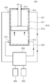
도 5는 피스톤이 실린더의 하부에서 상부로 이동할 때를 나타내는 도면이고, 도 6은 피스톤의 속력이 조절되는 과정을 나타내는 플로우 차트이다.Fig. 5 is a view showing the piston moving from the lower part to the upper part of the cylinder, and Fig. 6 is a flowchart showing the process of controlling the speed of the piston.
도 5 및 도 6을 참조하여, 피스톤(812)의 속력이 설정 속력으로 조절되는 과정을 설명한다. 먼저, 피스톤(812)은 배관 제어 유닛(830)의 제어에 따라 실린더(811)의 하부에서 상부로 이동된다. 그리고, 센서들(816, 817)은 피스톤(812)의 이동에 따라 감지된 신호를 배관 제어 유닛(830)으로 송신하고, 배관 제어 유닛(830)은 수신된 신호를 통해 피스톤(812)의 이동 속력을 감지한다. 피스톤(812)이 실린더(811)의 하부에서 상부로 이동할 때, 제 1 배관(821)의 유체는 실린더(811)에서 제 1 배관 제어 부재(832a)로 유동하고, 제 2 배관(822)의 유체는 제 2 배관 제어 부재(832b)에서 실린더(811)로 유동한다. 구체적으로, 배관 제어 유닛(830)은 실린더(811) 상부의 유체가 제 1 배관(821)을 유동한 후 외부로 배출되도록 제 1 배관 제어 부재(832a)를 제어할 수 있다. 또한, 배관 제어 유닛(830)은 유체 공급원(850)의 유체가 제 2 배관(822)을 통해 실린더(811)의 하부로 공급되도록 제 2 배관 제어 부재(832b)를 제어할 수 있다. 이 때, 모듈 제어부(831)는 초기 제어 값에 따라 배관 제어 모듈(832)을 제어한다. 초기 제어 값은 배관 제어 모듈(832)에 인가될 수 있는 값의 상한과 하한 사이의 임의 값일 수 있다. 예를 들어, 배관 제어 모듈(832)을 제어하기 위한 신호가 전압인 경우, 초기 제어 값은 배관 제어 모듈(832)에 인가될 수 있는 전압 값의 상한 값과 하한 값 사이의 크기를 갖는 전압 일 수 있다. 일 예로, 초기 제어 값으로 인가된 전압의 크기는 상한 값과 하한 값의 평균 값 일 수 있다. 또한, 초기 제어 값으로 인가된 전압의 크기는 평균 값 보다 크거나 작을 수 도 있다.Referring to Figs. 5 and 6, a process in which the speed of the
배관 제어 유닛(830)은 감지된 피스톤(812)의 계측 속력을 설정 속력과 비교한 후, 피스톤(812)의 계측 속력이 설정 속력과 다르면 제어 값을 수정한다. The
계측 속력과 설정 속력의 비교에는 오차 범위가 고려될 수 있다. 예를 들어, 계측 속력이 설정 속력을 포함하는 일정 범위에 속하면 계측 속력이 설정 속력을 만족하는 것으로 판단될 수 있다. 오차 범위의 상한 값은 조절될 수 있다. 또한, 오차 범위의 하한은 조절될 수 있다.An error range can be considered for comparison between the measurement speed and the set speed. For example, if the measurement speed is within a certain range including the set speed, it can be determined that the measurement speed satisfies the set speed. The upper limit value of the error range can be adjusted. Further, the lower limit of the error range can be adjusted.
계측 속력이 설정 속력을 벗어나면, 배관 제어 유닛(830)은 제어 값을 수정한다. 구체적으로, 계측 속력이 설정 속력보다 작은 경우, 배관 제어 유닛(830)은 제어 값을 증가 시킨다. 그리고, 계측 속력이 설정 속력보다 큰 경우, 배관 제어 유닛(830)은 제어 값을 감소 시킨다. 이 때, 제어 값의 수정에는 계측 속력이 설정 속력에 대해 갖는 차이가 고려될 수 있다. 예를 들어, 배관 제어 유닛(830)은 설정 속력에 대한 계측 속력의 차이 값에 계측 상수를 곱한 값만큼 제어 값을 변화 시킬 수 있다. 이와 같은 피스톤(812)의 속력 감지와 제어 값의 수정은 피스톤(812)의 속력이 설정 속력으로 조절될 때까지 반복 수행된다.When the measurement speed is out of the set speed, the
제어 값의 변화에 따라 피스톤(812)의 속도 조절을 위해 변하는 값은 배관(821, 822)을 유동하는 유체의 유량일 수 있다. 즉, 배관(821, 822)을 유동하는 유체의 양이 증가되면, 피스톤(812)의 이동 속도가 증가되고, 배관(821, 822)을 유동하는 유체의 양이 감소되면, 피스톤(812)의 이동 속도가 감소될 수 있다. 따라서, 배관 제어 유닛(830)은 제 1 배관(821)을 통해 배출되는 유체의 유량이 변하도록 제어 값을 조절할 수 있다.또한, 배관 제어 유닛(830)은 제 2 배관(822)을 통해 유입되는 유체의 유량이 변하도록 제어 값을 조절할 수 있다. 또한, 배관 제어 유닛(830)은 제 1 배관(821)을 통해 배출되는 유체의 유량과 제 2 배관(822)을 통해 유입되는 유체의 유양이 함께 변하도록 제어 값을 조절할 수 있다.The value varying for the control of the speed of the
또한, 제어 값의 변화에 따라 피스톤(812)의 속도 조절을 위해 변하는 값은 배관(821, 822)을 유동하는 유체의 압력일 수 도 있다. 즉, 배관(821, 822)을 유동하는 유체의 압력이 증가되면, 피스톤(812)의 이동 속도가 증가되고, 배관(821, 822)을 유동하는 유체의 압력이 감소되면, 피스톤(812)의 이동 속도가 감소될 수 있다. 하나의 요인으로, 피스톤(812)과 실린더(811) 사이에 작용하는 마찰력은 피스톤(812)이 이동 중일 때 비해, 피스톤(812)이 이동을 개시할 때 크게 작용하는데 기인할 수 있다. 또 다른 요인으로, 유체의 압력에 따라 변하는 유체의 밀도 변화에 기인할 수 있다. 따라서, 배관 제어 유닛(830)은 제 1 배관(821)을 통해 배출되는 유체의 압력이 변하도록 제어 값을 조절 할 수 있다. 또한, 배관 제어 유닛(830)은 제 2 배관(822)을 통해 유입되는 유체의 압력이 변하도록 제어 값을 조절할 수 도 있다. 또한, 배관 제어 유닛(830)은 제 1 배관(821)을 통해 배출되는 유체의 압력과 제 2 배관(822)을 통해 유입되는 유체의 압력이 함께 변하도록 제어 값을 조절할 수 도 있다.Further, the value varying for the speed control of the
도 7은 피스톤이 실린더의 상부에서 하부로 이동할 때를 나타내는 도면이다.7 is a view showing when the piston moves from the upper part to the lower part of the cylinder.
도 7을 참조하면, 피스톤(812)이 실린더(811)의 상부에서 하부로 이동할 때, 제 1 배관(821)의 유체는 제 1 배관 제어 부재(832a)에서 실린더(811)로 유동하고, 제 2 배관(822)의 유체는 실린더(811)에서 제 2 배관 제어 부재(832b)로 유동한다. 구체적으로, 배관 제어 유닛(830)은 유체 공급원(850)의 유체가 제 1 배관(821)을 통해 실린더(811)의 상부로 공급되도록 제 1 배관 제어 부재(832a)를 조절한다. 그리고, 배관 제어 유닛(830)은 실린더(811) 하부의 유체가 제 2 배관(822)을 유동한 후 외부로 배출되도록 제 2 배관 제어 부재(832b)를 조절한다. 이때, 배관 제어 유닛(830)은 도 6의 피스톤(812)이 실린더(811)의 하부에서 상부로 이동할 때와 유사한 방법으로 제어 값을 통해 제 1 배관 제어 부재(832a) 또는 제 2 배관 제어 부재(832b)의 동작을 제어한다. 배관 제어 유닛(830)은 실린더(811)가 하부에서 상부로 이동할 때의 제어에 사용하는 제어 값과 실리더(811)가 상부에서 하부로 이동할 때의 제어에 사용하는 제어 값을 개별적으로 설정할 수 있다. 초기 제어 값에 따라 이동 된 피스톤(812)의 속력을 감지한 후, 피스톤(812)의 계측 속력을 설정 속력과 비교하여 제어 값을 조절하는 단계는 도 5의 피스톤(812)이 실린더(811)의 하부에서 상부로 이동할 때와 유사하므로 반복된 설명은 생략한다.7, when the
본 발명의 일 실시 예에 따르면, 목표로 하는 피스톤(812)의 속력이 설정되면, 피스톤(812)의 속력 제어를 위한 제어 값이 자동으로 조절 될 수 있다.According to one embodiment of the present invention, when the speed of the
도 8은 다른 실시 예에 따라 피스톤의 속력이 조절되는 과정을 나타내는 플로우 차트이다.8 is a flowchart showing a process of controlling the speed of the piston according to another embodiment.
도 8을 참조하면, 피스톤(812)의 계측 속력이 설정 속력을 만족하는 경우, 제어 값 조절의 종료에 앞서 종료 조건을 만족 하는지 추가적으로 검토될 수 있다. 예를 들어, 배관 제어 유닛(830)은 조절 된 제어 값에 따라 피스톤(812)을 설정 횟수 이상 반복하여 이동 시키면서 속력을 감지할 수 있다. 그리고, 설정 횟수 동안 피스톤(812)의 계측 속력이 설정 속력을 만족하면, 제어 값의 조절이 완료된 것으로 할 수 있다. 이 때, 설정 횟수는 1 이상의 자연수이다.Referring to FIG. 8, if the measurement speed of the
이상의 상세한 설명은 본 발명을 예시하는 것이다. 또한 전술한 내용은 본 발명의 바람직한 실시 형태를 나타내어 설명하는 것이며, 본 발명은 다양한 다른 조합, 변경 및 환경에서 사용할 수 있다. 즉 본 명세서에 개시된 발명의 개념의 범위, 저술한 개시 내용과 균등한 범위 및/또는 당업계의 기술 또는 지식의 범위내에서 변경 또는 수정이 가능하다. 저술한 실시예는 본 발명의 기술적 사상을 구현하기 위한 최선의 상태를 설명하는 것이며, 본 발명의 구체적인 적용 분야 및 용도에서 요구되는 다양한 변경도 가능하다. 따라서 이상의 발명의 상세한 설명은 개시된 실시 상태로 본 발명을 제한하려는 의도가 아니다. 또한 첨부된 청구범위는 다른 실시 상태도 포함하는 것으로 해석되어야 한다.The foregoing detailed description is illustrative of the present invention. In addition, the foregoing is intended to illustrate and explain the preferred embodiments of the present invention, and the present invention may be used in various other combinations, modifications and environments. That is, it is possible to make changes or modifications within the scope of the concept of the invention disclosed in this specification, within the scope of the disclosure, and / or within the skill and knowledge of the art. The embodiments described herein are intended to illustrate the best mode for implementing the technical idea of the present invention and various modifications required for specific applications and uses of the present invention are also possible. Accordingly, the detailed description of the invention is not intended to limit the invention to the disclosed embodiments. It is also to be understood that the appended claims are intended to cover further embodiments.
10: 인덱스 모듈
20: 공정 처리 모듈
120: 로드 포트
140: 이송 프레임
220: 버퍼 유닛
240: 이송 챔버
260: 공정 챔버
800: 구동 어셈블리
810: 구동 부재
821: 제 1 배관
822: 제 2 배관
830: 배관 제어 유닛
850: 유체 공급원
860: 제어 부재10: Index module 20: Process processing module
120: load port 140: transport frame
220: buffer unit 240: transfer chamber
260: process chamber 800: drive assembly
810: driving member 821: first pipe
822: Second piping 830: Piping control unit
850: fluid source 860: control member
Claims (7)
상기 피스톤을 이동 가능하게 수용하고, 상기 피스톤의 구동을 위한 유체가 공급되는 배관들에 연결되는 실린더;
상기 실린더의 내부에 위치되는 센서들; 및
상기 배관을 유동하는 유체를 통해 상기 피스톤의 속력을 제어하되, 상기 센서들에 의해 감지된 신호를 바탕으로 계측된 상기 피스톤의 계측 속력을 설정 속력과 비교하는 방식으로 상기 피스톤의 속력을 자동으로 조절하는 배관 제어 유닛을 포함하는 구동 어셈블리.piston;
A cylinder movably receiving the piston and connected to pipes through which fluid for driving the piston is supplied;
Sensors positioned within the cylinder; And
Controlling the speed of the piston through the fluid flowing through the pipe and automatically adjusting the speed of the piston by comparing the measurement speed of the piston measured based on the signal sensed by the sensors with the set speed The piping control unit comprising:
상기 센서들은,
상기 피스톤이 이동하는 방향의 일측에 위치되는 제 1 센서; 및
상기 피스톤이 이동하는 방향의 타측에 위치되는 제 2 센서를 포함하는 구동 어셈블리.The method according to claim 1,
The sensors,
A first sensor positioned at one side of a direction in which the piston moves; And
And a second sensor positioned on the other side of the direction in which the piston moves.
상기 배관 제어 유닛은 상기 제 1 센서와 상기 제 2 센서가 송신하는 신호의 시간차를 이용해 상기 계측 속력을 산출하는 구동 어셈블리.3. The method of claim 2,
Wherein the piping control unit calculates the measurement speed using a time difference between signals transmitted from the first sensor and the second sensor.
상기 배관 제어 유닛은,
상기 배관들을 유동하는 유체를 제어하는 배관 제어 모듈; 및
제어 값을 통해 상기 배관 제어 모듈의 동작을 조절하는 모듈 제어부를 포함하는 구동 어셈블리.The method according to claim 1,
The piping control unit includes:
A pipe control module for controlling a fluid flowing through the pipes; And
And a module control unit for controlling the operation of the piping control module through a control value.
상기 배관 제어 모듈은 피에조 에추에이터를 포함하여 구성되는 구동 어셈블리.5. The method of claim 4,
Wherein the piping control module comprises a piezo actuator.
상기 제어 값은 전압 값으로 제공되는 구동 어셈블리.6. The method of claim 5,
Wherein the control value is provided as a voltage value.
상기 모듈 제어부는 상기 제어 값을 초기 제어 값으로 설정하여 상기 피스톤을 구동한 후, 산출된 상기 계측 속력에 따라 상기 제어 값을 증가 또는 감소 시키는 작업을 1회 이상 수행하여 상기 피스톤의 속력을 자동으로 조절하는 구동 어셈블리.The method according to claim 6,
Wherein the module control unit sets the control value as an initial control value and drives the piston and then performs an operation of increasing or decreasing the control value in accordance with the calculated measurement speed at least once to automatically speed the piston Adjustable drive assembly.
Priority Applications (1)
| Application Number | Priority Date | Filing Date | Title |
|---|---|---|---|
| KR1020140106303A KR102264294B1 (en) | 2014-08-14 | 2014-08-14 | Drive assembly |
Applications Claiming Priority (1)
| Application Number | Priority Date | Filing Date | Title |
|---|---|---|---|
| KR1020140106303A KR102264294B1 (en) | 2014-08-14 | 2014-08-14 | Drive assembly |
Publications (2)
| Publication Number | Publication Date |
|---|---|
| KR20160021402A true KR20160021402A (en) | 2016-02-25 |
| KR102264294B1 KR102264294B1 (en) | 2021-06-15 |
Family
ID=55446074
Family Applications (1)
| Application Number | Title | Priority Date | Filing Date |
|---|---|---|---|
| KR1020140106303A Active KR102264294B1 (en) | 2014-08-14 | 2014-08-14 | Drive assembly |
Country Status (1)
| Country | Link |
|---|---|
| KR (1) | KR102264294B1 (en) |
Cited By (1)
| Publication number | Priority date | Publication date | Assignee | Title |
|---|---|---|---|---|
| WO2021015591A1 (en) * | 2019-07-24 | 2021-01-28 | 정종홍 | Linear reciprocating drive apparatus for secondary battery manufacturing process |
Citations (4)
| Publication number | Priority date | Publication date | Assignee | Title |
|---|---|---|---|---|
| JPH10149977A (en) * | 1996-11-19 | 1998-06-02 | Tokyo Electron Ltd | Processing device control method and processing device |
| JP2000018207A (en) * | 1998-06-29 | 2000-01-18 | Tokyo Electron Ltd | Processing equipment |
| KR20060059735A (en) * | 2004-11-29 | 2006-06-02 | 삼성전자주식회사 | Lift device of semiconductor manufacturing equipment and its driving method |
| KR20070055154A (en) * | 2005-11-25 | 2007-05-30 | 삼성전자주식회사 | Semiconductor manufacturing apparatus comprising hydrauric cylinder |
-
2014
- 2014-08-14 KR KR1020140106303A patent/KR102264294B1/en active Active
Patent Citations (4)
| Publication number | Priority date | Publication date | Assignee | Title |
|---|---|---|---|---|
| JPH10149977A (en) * | 1996-11-19 | 1998-06-02 | Tokyo Electron Ltd | Processing device control method and processing device |
| JP2000018207A (en) * | 1998-06-29 | 2000-01-18 | Tokyo Electron Ltd | Processing equipment |
| KR20060059735A (en) * | 2004-11-29 | 2006-06-02 | 삼성전자주식회사 | Lift device of semiconductor manufacturing equipment and its driving method |
| KR20070055154A (en) * | 2005-11-25 | 2007-05-30 | 삼성전자주식회사 | Semiconductor manufacturing apparatus comprising hydrauric cylinder |
Cited By (1)
| Publication number | Priority date | Publication date | Assignee | Title |
|---|---|---|---|---|
| WO2021015591A1 (en) * | 2019-07-24 | 2021-01-28 | 정종홍 | Linear reciprocating drive apparatus for secondary battery manufacturing process |
Also Published As
| Publication number | Publication date |
|---|---|
| KR102264294B1 (en) | 2021-06-15 |
Similar Documents
| Publication | Publication Date | Title |
|---|---|---|
| US8033801B2 (en) | Liquid chemical supply system and liquid chemical supply control device | |
| US12228435B2 (en) | Flow control system, method, and apparatus | |
| US8757603B2 (en) | Low force substrate lift | |
| US8698052B2 (en) | Temperature control method of heat processing plate, computer storage medium, and temperature control apparatus of heat processing plate | |
| CN103125012B (en) | Substrate Handling System | |
| JP6691167B2 (en) | Mass flow controller and method for controlling fluid flow rate | |
| KR102546381B1 (en) | Reduced pressure drying apparatus, substrate processing apparatus, and reduced pressure drying method | |
| CN105659177B (en) | Pressure flow-rate controller | |
| TW202236490A (en) | Wafer lift pin system | |
| TW202225595A (en) | Pressure adjustment apparatus for controlling pressure in chamber and substrate processing apparatus including the same | |
| CN110957237B (en) | Wafer purging type shelf assembly and buffer module with same | |
| KR102304548B1 (en) | Valve device and control method using the same, fluid control device and semiconductor manufacturing device | |
| KR102264294B1 (en) | Drive assembly | |
| US11926502B2 (en) | Transport device | |
| KR20150077523A (en) | Unit for supplying chemical | |
| US20150117987A1 (en) | Substrate treating apparatus, drive assembly, and drive member controlling method | |
| KR20150050285A (en) | Substrate treating apparatus, drive assembly asd drive member control method | |
| KR20140089216A (en) | Unit for supplying chemical | |
| JP7460506B2 (en) | Substrate Processing Equipment | |
| JP5854335B2 (en) | Processing chamber pressure control method and processing chamber pressure control apparatus | |
| TWI765472B (en) | Flow control device and flow control method | |
| KR20200074952A (en) | Advanced vacuum process control | |
| KR102277541B1 (en) | Drive assembly | |
| KR101776021B1 (en) | Apparatus and method for treating a substrate | |
| KR20160023997A (en) | Drive assembly |
Legal Events
| Date | Code | Title | Description |
|---|---|---|---|
| PA0109 | Patent application |
St.27 status event code: A-0-1-A10-A12-nap-PA0109 |
|
| R17-X000 | Change to representative recorded |
St.27 status event code: A-3-3-R10-R17-oth-X000 |
|
| PG1501 | Laying open of application |
St.27 status event code: A-1-1-Q10-Q12-nap-PG1501 |
|
| A201 | Request for examination | ||
| PA0201 | Request for examination |
St.27 status event code: A-1-2-D10-D11-exm-PA0201 |
|
| D13-X000 | Search requested |
St.27 status event code: A-1-2-D10-D13-srh-X000 |
|
| D14-X000 | Search report completed |
St.27 status event code: A-1-2-D10-D14-srh-X000 |
|
| E902 | Notification of reason for refusal | ||
| PE0902 | Notice of grounds for rejection |
St.27 status event code: A-1-2-D10-D21-exm-PE0902 |
|
| T11-X000 | Administrative time limit extension requested |
St.27 status event code: U-3-3-T10-T11-oth-X000 |
|
| T11-X000 | Administrative time limit extension requested |
St.27 status event code: U-3-3-T10-T11-oth-X000 |
|
| E13-X000 | Pre-grant limitation requested |
St.27 status event code: A-2-3-E10-E13-lim-X000 |
|
| P11-X000 | Amendment of application requested |
St.27 status event code: A-2-2-P10-P11-nap-X000 |
|
| P13-X000 | Application amended |
St.27 status event code: A-2-2-P10-P13-nap-X000 |
|
| E701 | Decision to grant or registration of patent right | ||
| PE0701 | Decision of registration |
St.27 status event code: A-1-2-D10-D22-exm-PE0701 |
|
| GRNT | Written decision to grant | ||
| PR0701 | Registration of establishment |
St.27 status event code: A-2-4-F10-F11-exm-PR0701 |
|
| PR1002 | Payment of registration fee |
St.27 status event code: A-2-2-U10-U11-oth-PR1002 Fee payment year number: 1 |
|
| PG1601 | Publication of registration |
St.27 status event code: A-4-4-Q10-Q13-nap-PG1601 |
|
| PN2301 | Change of applicant |
St.27 status event code: A-5-5-R10-R13-asn-PN2301 St.27 status event code: A-5-5-R10-R11-asn-PN2301 |
|
| R18-X000 | Changes to party contact information recorded |
St.27 status event code: A-5-5-R10-R18-oth-X000 |
|
| PR1001 | Payment of annual fee |
St.27 status event code: A-4-4-U10-U11-oth-PR1001 Fee payment year number: 4 |
|
| PN2301 | Change of applicant |
St.27 status event code: A-5-5-R10-R13-asn-PN2301 St.27 status event code: A-5-5-R10-R11-asn-PN2301 |
|
| PR1001 | Payment of annual fee |
St.27 status event code: A-4-4-U10-U11-oth-PR1001 Fee payment year number: 5 |
|
| P22-X000 | Classification modified |
St.27 status event code: A-4-4-P10-P22-nap-X000 |