KR20160077286A - Hydro forming apparatus and method - Google Patents
Hydro forming apparatus and method Download PDFInfo
- Publication number
- KR20160077286A KR20160077286A KR1020140186041A KR20140186041A KR20160077286A KR 20160077286 A KR20160077286 A KR 20160077286A KR 1020140186041 A KR1020140186041 A KR 1020140186041A KR 20140186041 A KR20140186041 A KR 20140186041A KR 20160077286 A KR20160077286 A KR 20160077286A
- Authority
- KR
- South Korea
- Prior art keywords
- tubular material
- mold
- shape
- replacement
- tubular
- Prior art date
- Legal status (The legal status is an assumption and is not a legal conclusion. Google has not performed a legal analysis and makes no representation as to the accuracy of the status listed.)
- Ceased
Links
Images



Classifications
-
- B—PERFORMING OPERATIONS; TRANSPORTING
- B21—MECHANICAL METAL-WORKING WITHOUT ESSENTIALLY REMOVING MATERIAL; PUNCHING METAL
- B21D—WORKING OR PROCESSING OF SHEET METAL OR METAL TUBES, RODS OR PROFILES WITHOUT ESSENTIALLY REMOVING MATERIAL; PUNCHING METAL
- B21D26/00—Shaping without cutting otherwise than using rigid devices or tools or yieldable or resilient pads, i.e. applying fluid pressure or magnetic forces
- B21D26/02—Shaping without cutting otherwise than using rigid devices or tools or yieldable or resilient pads, i.e. applying fluid pressure or magnetic forces by applying fluid pressure
- B21D26/033—Deforming tubular bodies
-
- B—PERFORMING OPERATIONS; TRANSPORTING
- B21—MECHANICAL METAL-WORKING WITHOUT ESSENTIALLY REMOVING MATERIAL; PUNCHING METAL
- B21D—WORKING OR PROCESSING OF SHEET METAL OR METAL TUBES, RODS OR PROFILES WITHOUT ESSENTIALLY REMOVING MATERIAL; PUNCHING METAL
- B21D26/00—Shaping without cutting otherwise than using rigid devices or tools or yieldable or resilient pads, i.e. applying fluid pressure or magnetic forces
- B21D26/02—Shaping without cutting otherwise than using rigid devices or tools or yieldable or resilient pads, i.e. applying fluid pressure or magnetic forces by applying fluid pressure
- B21D26/033—Deforming tubular bodies
- B21D26/049—Deforming bodies having a closed end
Landscapes
- Physics & Mathematics (AREA)
- Fluid Mechanics (AREA)
- Engineering & Computer Science (AREA)
- Mechanical Engineering (AREA)
- Shaping Metal By Deep-Drawing, Or The Like (AREA)
Abstract
본 발명의 일 실시예에 따른 하이드로포밍 장치는 관형소재가 안착되며, 내측면에 성형될 형상이 형성되어 제공되는 금형부, 상기 관형소재의 양단부를 밀폐하게 결합되며, 상기 관형소재의 내부로 확관액을 공급하는 가압밀폐부 및 상기 확관액에 의한 가압력이 상기 관형소재의 일부분에 집중되도록, 상기 금형부의 일부에 교체되게 구비되는 교체슬리브부를 포함할 수 있다.
또한, 본 발명의 다른 실시예에 따른 하이드로포밍 방법은 일부에 교체슬리브부가 장착된 금형부에 관형소재를 안착시키는 안착단계, 상기 관형소재의 양단부를 밀폐시키는 밀폐단계, 밀폐된 상기 관형소재로 확관액을 공급하여, 상기 관형소재를 확관시키는 확관단계 및 상기 교체슬리브부를 제거 또는 교체 후에, 상기 관형소재로 확관액을 더 공급하는 교체성형단계를 포함할 수 있다.A hydroforming apparatus according to an embodiment of the present invention includes a mold part on which a tubular material is placed and which is provided with a shape to be formed on its inner surface, a tubular part which is hermetically coupled to both ends of the tubular material, And a replacement sleeve portion that is provided in a part of the mold portion so as to be concentrated on a part of the tubular material.
According to another aspect of the present invention, there is provided a method of hydroforming, comprising the steps of: placing a tubular material on a mold part having a replaceable sleeve part; sealing the both ends of the tubular material; An expanding step of supplying the tube fluid to expand the tubular material, and a replacement forming step of further supplying the tube fluid to the tubular material after the replacement sleeve part is removed or replaced.
Description
본 발명은 하이드로포밍 장치 및 하이드로포밍 방법에 관한 것으로, 더욱 상세하게는 확관액에 의한 가압력을 집중하여 성형할 수 있는 발명에 관한 것이다.BACKGROUND OF THE
하이드로포밍 공법은 유압이나 공압을 이용하여 피가공물을 확대 성형시키는 기계 판금의 특수한 가공법 중의 하나이다. 이러한 하이드로포밍 공법은 심용접(seam welding) 또는 저항용접된 관형소재를 대상으로 하여 관형소재의 양끝단을 펀치로 밀봉한 상태에서 관형소재 내부의 압력을 상승시켜서 원하는 형상으로 성형한다.The hydroforming method is one of the special processing methods of the mechanical sheet metal in which the workpiece is expanded and formed by using hydraulic pressure or pneumatic pressure. Such a hydroforming method is applied to seam welding or resistance welded tubular materials. Both ends of the tubular material are sealed with a punch, and the pressure inside the tubular material is increased to form a desired shape.
이러한 하이드로포밍 공법은 자동차용 휠림 등의 제조 등 자동차 가공 공정에 주로 적용되고 있는 기술이며, 특히 자동차용 강판을 가공하는 기술로 사용되고 있다.Such a hydroforming method is a technique that is mainly applied to an automobile processing process such as manufacture of an automobile wheel and the like, and is used particularly as a technique for processing a steel sheet for an automobile.
다시 말해, 하이드로포밍 공법은 도 1에 도시된 바와 같이, 일반적으로 용접된 튜브형의 관형소재(2')를 눕혀서 금형부(10')에 안착시키고, 상기 관형소재(2')의 양단부를 가압밀폐부(20')로 밀폐한 상태에서 상기 관형소재(2') 내부에 압력을 상승시켜 원하는 형상으로 성형하는 기술인 것이다.In other words, the hydroforming method is a method in which a generally tubular tubular material 2 'is laid down and placed on a mold part 10' as shown in Fig. 1, and both end portions of the tubular material 2 ' And the pressure is elevated inside the tubular material 2 'in a state of being hermetically sealed by the hermetically sealed part 20' to be molded into a desired shape.
이러한 경우에는, 확관액의 주입에 의한 가압력으로만 상기 관형소재(2')를 성형하기 때문에, 세밀한 제품 성형에 한계가 있어, 공정을 다단으로 나누어 성형하는 단점이 있다.In such a case, since the tubular material 2 'is formed only by the pressing force by the injection of the diluting fluid, there is a limit to detailed product molding, and there is a disadvantage that the process is divided into a plurality of steps.
즉, 확관액의 주입에 의한 가압력이 분산되어, 내면 밀착과 모서리 부분을 완전하게 채우기 어려워, 일부 밀착되지 않아 성형 하자로 발생되는 부분(e)이 생기게 되는 것이다.That is, the pressing force by the injection of the diluting liquid is dispersed, and it is difficult to completely fill the corner portion with the inner surface, and the portion (e) which is not partially adhered is generated.
또한, 다단으로 성형시에는 고중량의 금형부(10')를 교체하기가 어렵고, 교체에 의한 시간 지연도 크게 발생하며, 중간 성형된 관형소재(2')의 포지션을 동일하게 제공하기 어려워 성형 하자로 발전하는 문제도 있다. In addition, it is difficult to replace the mold portion 10 'with a heavy weight during molding in a multi-stage mold, a time delay due to replacement is considerably large, and it is difficult to provide the same position of the intermediate molded tubular material 2' There is also a problem of developing into.
따라서, 전술한 문제를 해결하기 위한, 하이드로포밍 장치 및 하이드로포밍 방법에 대한 연구가 필요하게 되었다.Therefore, there is a need for research on a hydroforming apparatus and a hydroforming method for solving the above-mentioned problems.
본 발명의 목적은 세밀한 성형이 가능하고, 다단 성형시의 시간 지연 및 관형소재의 위치 조정 오차에 의한 성형 하자가 발생하는 것을 방지할 수 있는 하이드로포밍 장치 및 하이드로포밍 방법을 제공하는 것이다.It is an object of the present invention to provide a hydroforming apparatus and a hydroforming method capable of finely forming, preventing formation of defects due to time delay in multi-step molding and position adjustment error of tubular material.
본 발명의 일 실시예에 따른 하이드로포밍 장치는 관형소재가 안착되며, 내측면에 성형될 형상이 형성되어 제공되는 금형부, 상기 관형소재의 양단부를 밀폐하게 결합되며, 상기 관형소재의 내부로 확관액을 공급하는 가압밀폐부 및 상기 확관액에 의한 가압력이 상기 관형소재의 일부분에 집중되도록, 상기 금형부의 일부에 교체되게 구비되는 교체슬리브부를 포함할 수 있다.A hydroforming apparatus according to an embodiment of the present invention includes a mold part on which a tubular material is placed and which is provided with a shape to be formed on its inner surface, a tubular part which is hermetically coupled to both ends of the tubular material, And a replacement sleeve portion that is provided in a part of the mold portion so as to be concentrated on a part of the tubular material.
또한, 본 발명의 일 실시예에 따른 하이드로포밍 장치의 상기 교체슬리브부는, 외측면은 상기 금형부 일부의 내측면 형상에 대응되는 형상으로 형성되며, 내측면은 상기 관형소재가 변형되지 않도록, 평면형상으로 제공되는 것을 특징으로 할 수 있다.In the hydroforming apparatus according to an embodiment of the present invention, the outer sleeve has a shape corresponding to an inner surface shape of a part of the mold part, and an inner surface of the sleeve part has a flat surface And is provided in a shape of a circle.
또한, 본 발명의 일 실시예에 따른 하이드로포밍 장치의 상기 교체슬리브부는, 외측면은 상기 금형부 일부의 내측면 형상에 대응되는 형상으로 형성되며, 내측면은 상기 관형소재의 변형을 단계적으로 지지하도록, 상기 관형소재의 중간 성형 형상으로 형성되어 제공되는 것을 특징으로 할 수 있다.In the hydroforming apparatus according to an embodiment of the present invention, the outer sleeve has a shape corresponding to an inner shape of a part of the mold part, and an inner surface of the sleeve part gradually deforms the tubular material The tubular material may be provided in the form of an intermediate molding of the tubular material.
또한, 본 발명의 일 실시예에 따른 하이드로포밍 장치의 상기 교체슬리브부의 외측면은 상기 금형부보다 경도가 작은 소재의 완충재로 형성되어 제공되는 것을 특징으로 할 수 있다.The outer surface of the replacement sleeve portion of the hydroforming apparatus according to an exemplary embodiment of the present invention may be formed of a cushioning material having a hardness lower than that of the mold portion.
또한, 본 발명의 일 실시예에 따른 하이드로포밍 장치의 상기 교체슬리브부는, 분할된 링 형상으로 제공되는 복수 개의 피스부재를 포함하며, 각각의 상기 피스부재의 일단부에는 돌출된 결합봉이 구비되고, 타단부에는 상기 결합봉이 삽입되는 결합홈이 구비된 것을 특징으로 할 수 있다.Further, the replacement sleeve portion of the hydroforming apparatus according to an embodiment of the present invention includes a plurality of piece members provided in a divided ring shape, each of the piece members has a protruding engagement rod at one end thereof, And the other end is provided with a coupling groove into which the coupling rod is inserted.
또한, 본 발명의 다른 실시예에 따른 하이드로포밍 방법은 일부에 교체슬리브부가 장착된 금형부에 관형소재를 안착시키는 안착단계, 상기 관형소재의 양단부를 밀폐시키는 밀폐단계, 밀폐된 상기 관형소재로 확관액을 공급하여, 상기 관형소재를 확관시키는 확관단계 및 상기 교체슬리브부를 제거 또는 교체 후에, 상기 관형소재로 확관액을 더 공급하는 교체성형단계를 포함할 수 있다.According to another aspect of the present invention, there is provided a method of hydroforming, comprising the steps of: placing a tubular material on a mold part having a replaceable sleeve part; sealing the both ends of the tubular material; An expanding step of supplying the tube fluid to expand the tubular material, and a replacement forming step of further supplying the tube fluid to the tubular material after the replacement sleeve part is removed or replaced.
또한, 본 발명의 다른 실시예에 따른 하이드로포밍 방법의 상기 교체성형단계는, 상기 관형소재가 상기 금형부에 안착된 상태에서 상기 교체슬리브부의 교체가 가능하도록, 상기 교체슬리브부를 적어도 2 분할 링 형상으로 제공하며, 안착된 상기 관형소재와 상기 금형부 사이의 틈으로 이탈 또는 삽입시키는 것을 특징으로 할 수 있다.Further, in the alternative forming step of the hydroforming method according to another embodiment of the present invention, the replacement sleeve portion may be formed in at least two split ring shapes such that the replacement sleeve portion can be replaced while the tubular material is seated on the mold portion. And separating or inserting the tubular material into the gap between the tubular material and the mold part.
본 발명의 하이드로포밍 장치 및 하이드로포밍 방법은 확관액 공급에 의한 가압력을 관형소재의 일부분에 집중할 수 있어, 세밀한 성형이 가능한 이점을 가질 수 있다.The hydroforming apparatus and the hydroforming method of the present invention can concentrate the pressing force by the supply of the diluting fluid to a part of the tubular material and can have an advantage that fine molding can be performed.
또한, 금형부의 교체하지 않고도 일부 성형 형상을 다단으로 변경하며 상기 관형소재를 성형할 수 있어, 다단 성형에 시간을 단축시킬 수 있는 이점도 있다.Further, the tubular material can be formed by changing a part of the forming shape into a multi-step without replacing the mold part, and there is an advantage that the time for multi-step molding can be shortened.
더하여, 금형부에 안착된 상기 관형소재의 이동을 방지하고 연속적인 다단 성형이 가능하기 때문에, 상기 관형소재의 포지션 변경에 의한 성형 하자가 발생하는 것을 방지할 수 있는 효과도 있다.In addition, since the tubular material placed on the mold part is prevented from moving and continuous multi-step molding is possible, it is possible to prevent molding defects due to the position change of the tubular material.
이에 의해, 제품 생산의 비용 및 시간의 낭비를 줄여 생산 효율성을 향상시키고, 제품의 품질을 향상시킬 수 있는 효과를 가질 수 있게 된다.As a result, it is possible to reduce the cost and time of the production of the product, thereby improving the production efficiency and improving the quality of the product.
도 1은 종래의 하이드로포밍 장치를 도시한 도면이다.
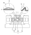
도 2는 본 발명의 하이드로포밍 장치를 도시한 단면도이다.
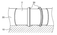
도 3은 본 발명의 하이드로포밍 장치에서 교체슬리브부 주변을 도시한 사시도이다.
도 4는 본 발명의 하이드로포밍 장치에서 교체슬리브부를 도시한 정면도이다.
도 5 및 도 6은 본 발명의 하이드로포밍 장치에서 피스부재를 도시한 도면이다.1 is a view showing a conventional hydroforming apparatus.
2 is a sectional view showing the hydroforming apparatus of the present invention.
3 is a perspective view showing the vicinity of the replacement sleeve portion in the hydroforming apparatus of the present invention.
4 is a front view showing the replacement sleeve portion in the hydroforming apparatus of the present invention.
5 and 6 are diagrams showing piece members in the hydroforming apparatus of the present invention.
이하에서는 도면을 참조하여 본 발명의 구체적인 실시예를 상세하게 설명한다. 다만, 본 발명의 사상은 제시되는 실시예에 제한되지 아니하고, 본 발명의 사상을 이해하는 당업자는 동일한 사상의 범위 내에서 다른 구성요소를 추가, 변경, 삭제 등을 통하여, 퇴보적인 다른 발명이나 본 발명 사상의 범위 내에 포함되는 다른 실시예를 용이하게 제안할 수 있을 것이나, 이 또한 본원 발명 사상 범위 내에 포함된다고 할 것이다.Hereinafter, specific embodiments of the present invention will be described in detail with reference to the drawings. It will be apparent to those skilled in the art that various modifications and variations can be made in the present invention without departing from the spirit or scope of the inventive concept. Other embodiments falling within the scope of the inventive concept may readily be suggested, but are also considered to be within the scope of the present invention.
또한, 각 실시예의 도면에 나타나는 동일한 사상의 범위 내의 기능이 동일한 구성요소는 동일한 참조부호를 사용하여 설명한다.
The same reference numerals are used to designate the same components in the same reference numerals in the drawings of the embodiments.
본 발명의 하이드로포밍 장치(1) 및 하이드로포밍 방법은 확관액에 의한 가압력을 집중하여 성형할 수 있는 발명에 관한 것이다.The hydroforming apparatus (1) and the hydroforming method of the present invention relate to an invention capable of concentrating the pressing force by the diluting fluid.
즉, 본 발명의 하이드로포밍 장치(1) 및 하이드로포밍 방법은 확관액 공급에 의한 가압력을 관형소재(2)의 일부분에 집중할 수 있어, 세밀한 성형이 가능한 것이다.That is, in the hydroforming apparatus (1) and the hydroforming method of the present invention, the pressing force due to the supply of the diluted fluid can be concentrated on a part of the tubular material (2), enabling fine molding.
또한, 금형부(10)의 교체하지 않고도 일부 성형 형상을 다단으로 변경하며 상기 관형소재(2)를 성형할 수 있어, 다단 성형에 시간을 단축시킬 수 있고, 금형부(10)에 안착된 상기 관형소재(2)의 이동을 방지하고 연속적인 다단 성형이 가능하기 때문에, 상기 관형소재(2)의 포지션 변경에 의한 성형 하자가 발생하는 것을 방지할 수 있다.
In addition, the
구체적으로, 도 2는 본 발명의 하이드로포밍 장치(1)를 도시한 단면도이고, 도 3은 본 발명의 하이드로포밍 장치(1)에서 교체슬리브부(30) 주변을 도시한 사시도이며, 도 5는 본 발명의 하이드로포밍 장치(1)에서 피스부재(31)를 도시한 도면이다.3 is a perspective view showing the periphery of the
도 2, 도 3 및 도 5를 참조하면, 본 발명의 일 실시예에 따른 하이드로포밍 장치(1)는 관형소재(2)가 안착되며, 내측면(30b)에 성형될 형상이 형성되어 제공되는 금형부(10), 상기 관형소재(2)의 양단부를 밀폐하게 결합되며, 상기 관형소재(2)의 내부로 확관액을 공급하는 가압밀폐부(20) 및 상기 확관액에 의한 가압력이 상기 관형소재(2)의 일부분에 집중되도록, 상기 금형부(10)의 일부에 교체되게 구비되는 교체슬리브부(30)를 포함할 수 있다.2, 3, and 5, a
즉, 관형소재(2)에 대한 확관액에 의한 성형시에, 많은 변형이 필요한 부분은 다른 부분에 비하여 상대적으로 더 큰 가압력을 제공해야 하는데, 상기 확관액의 공급에 의한 가압력이 분산되면, 변형이 많이 필요한 부분은 필요로 하는 성형이 완전하게 되지 않는 문제가 발생하기 때문에, 가압력을 집중할 수 있는 구성을 제시한 것이다.
That is, at the time of forming the tubular material (2) by the dilatation fluid, a portion requiring much deformation is required to provide a relatively larger pressing force as compared with the other portions. When the pressing force by the supply of the dilatation fluid is dispersed, A problem that the necessary molding is not completed is caused in a portion where a large amount of the pressing force is required.
상기 금형부(10)는 상기 관형소재(2)에 의해서 성형될 제품의 형상이 형성되어 제공되며, 상기 관형소재(2)의 확관시에 내측면(30b)에 상기 관형소재(2)가 밀착되어 제품의 형상을 형성하게 된다.The tubular material (2) is provided with a shape of a product to be formed by the tubular material (2), and the tubular material (2) is adhered to the inner side surface (30b) when the tubular material Thereby forming the shape of the product.
상기 금형부(10)는 일례로 하부금형(12)과 상부금형(11)으로 제공될 수 있으며, 하부금형(12)에 상기 관형소재(2)가 안착된 후에 상기 관형소재(2)의 상측으로 상기 상부금형(11)이 하강하여 상기 관형소재(2)의 외부면에 상기 금형부(10)를 제공할 수 있다.
The
상기 가압밀폐부(20)는 상기 관형소재(2)를 밀폐시킨 뒤에 상기 관형소재(2) 내부로 확관액을 공급하여 가압력을 제공하는 역할을 하게 된다.The pressure
즉, 상기 금형부(10)에 안착된 상기 관형소재(2)의 양단부를 상기 가압밀폐부(20)가 밀폐하게 되며, 상기 가압밀폐부(20)에 형성된 유로를 통하여 상기 확관액을 공급하여 상기 관형소재(2)를 성형하게 되는 것이다.That is, both end portions of the
이를 위해, 상기 가압밀폐부(20)는 상기 관형소재(2)의 양측 단부에 삽입되는 펀치부재와 상기 펀치부재를 이동시키는 이동실린더, 상기 펀치부재를 통하여 외부에 제공되는 확관액 저장소로부터 확관액을 공급하는 펌프유닛 등이 제공될 수 있다.
To this end, the pressurized sealing
상기 교체슬리브부(30)는 상기 금형부(10)에 교체되게 제공될 수 있는 추가적인 금형보조부재로써, 상기 관형소재(2)의 성형시에 변형이 많이 일어나는 부분에 가압력을 집중하게 하는 역할을 하게 된다.The
이를 위해서, 상기 교체슬리브부(30)는 상기 관형소재(2)에서 변형이 비교적 적은 부분에 가압력이 작용하는 것을 방지하거나, 상기 관형소재(2)에서 변형이 비교적 많은 부분에 변형을 단계적으로 실시하게 제공될 수 있다.
For this purpose, the
다시 말해, 도 2에 확대 도시한 바와 같이, 상기 금형부(10)의 일부에 상기 교체슬리브부(30)를 제공하고 있는데, 상기 관형소재(2)의 변형을 방지하기 위해, 내측면(30b)은 평평하게 제시하고 있다.2, the
즉, 본 발명의 일 실시예에 따른 하이드로포밍 장치(1)의 상기 교체슬리브부(30)는, 외측면(30a)은 상기 금형부(10) 일부의 내측면(30b) 형상에 대응되는 형상으로 형성되며, 내측면(30b)은 상기 관형소재(2)가 변형되지 않도록, 평면형상으로 제공되는 것을 특징으로 할 수 있다.That is, in the
이렇게 상기 관형소재(2)와 접하게 제공되는 상기 교체슬리브부(30)의 내측면(30b)을 평면형상으로 제공하면, 상기 관형소재(2) 내부에 확관액이 공급되더라도, 잉여 확관액은 상기 교체슬리브부(30)가 제공되지 않는 부분으로 집중될 수 있어, 가압력이 집중될 수 있는 것이다.
The
또한, 상기 관형소재(2)의 변형을 다단으로 형성하기 위해서는 변형이 많이 일어나는 부분의 금형부(10)에 중간형상이 형성된 내측면(30b)을 제공하는 교체슬리브부(30)를 제공할 수 있다.Further, in order to form the deformation of the
즉, 본 발명의 일 실시예에 따른 하이드로포밍 장치(1)의 상기 교체슬리브부(30)는, 외측면(30a)은 상기 금형부(10) 일부의 내측면(30b) 형상에 대응되는 형상으로 형성되며, 내측면(30b)은 상기 관형소재(2)의 변형을 단계적으로 지지하도록, 상기 관형소재(2)의 중간 성형 형상으로 형성되어 제공되는 것을 특징으로 할 수 있다.That is, in the
이러한 다단 성형은 변형이 많이 일어나는 부분도 다른 부분과 유사한 정도의 가압력만이 제공되어도 되기 때문에, 성형의 하자를 방지할 수 있고, 최종 형상은 상기 교체슬리브부(30)를 제거한 후에 확관액을 공급하여 최종적으로 성형이 마무리될 수 있다. 이때 최종 형상의 성형시에도 잉여 확관액은 아직 변형이 일어나지 않은 부분으로 집중되어 완전한 성형을 완료할 수 있게 된다.
In this multi-step molding, only a pressing force similar to that of the other parts can be provided at the part where the deformation is likely to occur. Therefore, the defective molding can be prevented, and the final shape can be obtained by removing the
한편, 상기 교체슬리브부(30)의 외측면(30a)에는 금형부(10)의 손상을 방지하기 위해 완충재로 형성될 수 있는데, 이에 대한 자세한 설명은 도 6을 참조하여 후술한다.The
그리고, 상기 교체슬리브부(30)는 교체 또는 제거를 용이하게 하면서도, 중간 성형된 상기 관형소재(2)의 포지션이 변경되는 것을 방지하기 위해서, 분할된 피스부재(31)로 제공될 수 있는데, 이에 대한 자세한 설명은 도 4를 참조하여 후술한다.
The
도 4는 본 발명의 하이드로포밍 장치(1)에서 교체슬리브부(30)를 도시한 정면도로써, 이를 참조하면, 본 발명의 일 실시예에 따른 하이드로포밍 장치(1)의 상기 교체슬리브부(30)는, 분할된 링 형상으로 제공되는 복수 개의 피스부재(31)를 포함하며, 각각의 상기 피스부재(31)의 일단부에는 돌출된 결합봉(32)이 구비되고, 타단부에는 상기 결합봉(32)이 삽입되는 결합홈(33)이 구비된 것을 특징으로 할 수 있다.4 is a front view showing the
즉, 상기 교체슬리브부(30)의 교체 또는 제거를 용이하게 하면서도, 중간 성형된 상기 관형소재(2)의 포지션이 변경되는 것을 방지하기 위한 구성을 제시한 것이다.That is, the present invention provides a structure for preventing the position of the intermediate formed
다시 말해, 상기 교체슬리브부(30)를 상기 관형소재(2)와 상기 금형부(10) 사이에 끼워 넣거나 뺄 수 있도록, 분할된 형태의 복수의 피스부재(31)로 제공한 것이며, 상기 관형소재(2)가 원통형이기 때문에, 분할된 링 형상으로 상기 피스부재(31)를 제공하는 것이 바람직한 것이다.In other words, the
더하여, 상기 피스부재(31)들 사이의 결합을 위한 구조로써, 결합봉(32), 결합홈(33)이 제공될 수 있다. 즉, 상기 피스부재(31)의 일단부에 결합봉(32)이 형성되고, 타단부에 결합홈(33)이 형성되어, 상기 결합홈(33)에 상기 결합봉(32)이 삽입되어 조립 결합될 수 있는 것이다.In addition, as the structure for coupling between the
그리고, 상기 피스부재(31)가 분할의 정도는 상기 금형부(10)의 분할과 대응하게 제공되는 것이 바람직하다. 일례로, 상기 금형부(10)가 상부금형(11), 하부금형(12)의 두 개로 제공되는 경우에는 상기 피스부재(31)도 두 개로 분할된 형상으로 제공하는 것이 바람직하다.It is preferable that the degree of the division of the
특히, 상기 피스부재(31)의 교체의 경우에는, 상기 하부금형(12)에 상기 관형소재(2)가 안착된 상태에서 상기 상측의 피스부재(31)를 우선 빼고, 상기 하부금형(12)과 상기 관형소재(2) 사이에 위치하는 하측 피스부재(31)를 빼고 다음 단계의 확관 성형을 실시할 수 있다.Particularly, in the case of replacing the
즉, 상기 관형소재(2)의 포지션을 변경하지 않고 다음 단계의 성형을 실시함으로써, 상기 관형소재(2)의 포지션 변경에 의하여 성형 하자가 발생하는 것을 방지할 수 있게 된다.
That is, by performing the molding at the next step without changing the position of the
도 6은 본 발명의 하이드로포밍 장치(1)에서 피스부재(31)를 도시한 도면으로써, 이를 참조하면, 본 발명의 일 실시예에 따른 하이드로포밍 장치(1)의 상기 교체슬리브부(30)의 외측면(30a)은 상기 금형부(10)보다 경도가 작은 소재의 완충재로 형성되어 제공되는 것을 특징으로 할 수 있다.FIG. 6 is a view showing the
즉, 상기 교체슬리브부(30)의 외측면(30a)에는 금형부(10)의 손상을 방지하기 위해 완충재로 형성될 수 있는 것이다. 상기 완충재의 일례로는 나일론 종류가 있을 수 있다.
That is, the
본 발명의 다른 실시예에 따른 하이드로포밍 방법은 일부에 교체슬리브부(30)가 장착된 금형부(10)에 관형소재(2)를 안착시키는 안착단계, 상기 관형소재(2)의 양단부를 밀폐시키는 밀폐단계, 밀폐된 상기 관형소재(2)로 확관액을 공급하여, 상기 관형소재(2)를 확관시키는 확관단계 및 상기 교체슬리브부(30)를 제거 또는 교체 후에, 상기 관형소재(2)로 확관액을 더 공급하는 교체성형단계를 포함할 수 있다.The hydroforming method according to another embodiment of the present invention includes a step of placing a
또한, 본 발명의 다른 실시예에 따른 하이드로포밍 방법의 상기 교체성형단계는, 상기 관형소재(2)가 상기 금형부(10)에 안착된 상태에서 상기 교체슬리브부(30)의 교체가 가능하도록, 상기 교체슬리브부(30)를 적어도 2 분할 링 형상으로 제공하며, 안착된 상기 관형소재(2)와 상기 금형부(10) 사이의 틈으로 이탈 또는 삽입시키는 것을 특징으로 할 수 있다.In the alternative forming step of the hydroforming method according to another embodiment of the present invention, the
즉, 교체슬리브부(30)에 의해, 확관액에 의한 가압력을 집중하게 제공함으로써, 관형소재(2)를 세밀하게 성형할 수 있는 방법을 제시한 것이다.
That is, the present invention provides a method by which the
상기 안착단계는 상기 관형소재(2)를 안착시켜 제공하는 단계이다. 특히, 상기 안착단계에서는 상기 교체슬리브부(30)가 일부 장착된 금형부(10)에 상기 관형소재(2)를 안착시킴으로써, 일부 형상에 대한 가압력을 증가시킬 수 있다. 이와 같이 가압력을 집중시키는 원리는 전술하였다.
The seating step is a step of seating and providing the tubular material (2). Particularly, in the seating step, the
상기 밀폐단계는 안착된 상기 관형소재(2)의 양단부를 밀폐시키는 단계로써, 이후의 확관액 공급에서 상기 확관액이 누출되는 것을 방지하여, 가압력을 유지하기 위한 것이다.
The sealing step is a step of sealing both ends of the seated
상기 확관단계는 밀폐된 상기 관형소재(2) 내부에 확관액을 주입하여 가압력에 의해서, 상기 금형에 밀착하게 상기 관형소재(2)를 확관시키는 단계이다. 이에 의해서, 상기 관형소재(2)는 상기 금형부(10)에 대응되는 형상으로 성형될 수 있다.The expanding step is a step of expanding the tubular material (2) in close contact with the mold by a pressing force by injecting the expanded liquid into the closed tubular material (2). Accordingly, the
다만, 다른 형상에 비하여 상기 관형소재(2)의 변형이 많이 필요한 형상의 경우에는 동일한 가압력을 제공하면 세밀한 가공이 안되는 것이 있는데, 이는 후술할 교체성형단계에 의해서 해결될 수 있다.
However, in the case of a shape requiring much deformation of the
상기 교체성형단계는 상기 금형부(10) 중에서 일부 형상에 교체슬리브부(30)를 제공하여, 상기 교체슬리브부(30)가 제공되지 않은 부분에 가압력이 집중될 수 있게 제공하는 역할을 한다. The replacement molding step serves to provide the
즉, 잉여 확관액이 일부 형상에 집중될 수 있어, 동일한 확관액을 공급하더라도 상대적으로 더 큰 가압력을 제공할 수 있게 되는 것이다.That is, the surplus expansion liquid can be concentrated on some shape, and even if the same expansion liquid is supplied, a relatively larger pressing force can be provided.
여기서, 상기 교체성형단계는 상기 교체슬리브부(30)의 교체 또는 제거시에도 상기 관형소재(2)의 포지션을 변경하지 않도록 제공함으로써, 상기 관형소재(2)의 포지션 변경에 의한 성형 하자가 발생하는 것을 방지할 수 있다. In this case, the replacement forming step is provided so as not to change the position of the
즉, 상기 관형소재(2)가 상기 금형부(10)의 하부금형(12)에 안착된 상태에서도 상기 교체슬리브부(30)가 분할된 피스부재(31)로 제공되고, 상기 교체슬리브부(30)는 상기 관형소재(2)와 하부금형(12) 사이의 틈을 이용하여 제거하거나, 삽입하여 상기 관형소재(2)의 포지션 변경 없이도 상기 관형소재(2)의 다단 성형을 가능하게 할 수 있는 것이다.That is, even when the
1: 하이드로포밍 장치
2 : 관형소재
10: 금형부
11: 상부금형
12: 하부금형
20: 가압밀폐부
30: 교체슬리브부
31: 피스부재
32: 결합봉
33: 결합홈1: Hydroforming device 2: Tubular material
10: mold part 11: upper mold part
12: Lower mold 20:
30: replacement sleeve portion 31: piece member
32: engaging rod 33: engaging groove
Claims (7)
상기 관형소재의 양단부를 밀폐하게 결합되며, 상기 관형소재의 내부로 확관액을 공급하는 가압밀폐부; 및
상기 확관액에 의한 가압력이 상기 관형소재의 일부분에 집중되도록, 상기 금형부의 일부에 교체되게 구비되는 교체슬리브부;
를 포함하는 하이드로포밍 장치.A mold part on which a tubular material is seated and provided with a shape to be formed on the inner surface thereof;
A pressurized sealing part hermetically coupled to both ends of the tubular material and supplying the expanded fluid to the inside of the tubular material; And
A replacement sleeve portion that is provided in a part of the mold portion so as to be concentrated on a portion of the tubular material;
≪ / RTI >
상기 교체슬리브부는,
외측면은 상기 금형부 일부의 내측면 형상에 대응되는 형상으로 형성되며,
내측면은 상기 관형소재가 변형되지 않도록, 평면형상으로 제공되는 것을 특징으로 하는 하이드로포밍 장치.The method according to claim 1,
The replaceable sleeve portion
The outer side surface is formed in a shape corresponding to the inner side surface shape of the mold part,
Wherein the inner surface is provided in a planar shape so that the tubular material is not deformed.
상기 교체슬리브부는,
외측면은 상기 금형부 일부의 내측면 형상에 대응되는 형상으로 형성되며,
내측면은 상기 관형소재의 변형을 단계적으로 지지하도록, 상기 관형소재의 중간 성형 형상으로 형성되어 제공되는 것을 특징으로 하는 하이드로포밍 장치.The method according to claim 1,
The replaceable sleeve portion
The outer side surface is formed in a shape corresponding to the inner side surface shape of the mold part,
Wherein the inner surface is formed in an intermediate molding shape of the tubular material so as to support the deformation of the tubular material in a stepwise manner.
상기 교체슬리브부의 외측면은 상기 금형부보다 경도가 작은 소재의 완충재로 형성되어 제공되는 것을 특징으로 하는 하이드로포밍 장치.The method according to claim 2 or 3,
Wherein the outer surface of the replacement sleeve portion is formed of a cushioning material having a hardness lower than that of the mold portion.
상기 교체슬리브부는,
분할된 링 형상으로 제공되는 복수 개의 피스부재;
를 포함하며,
각각의 상기 피스부재의 일단부에는 돌출된 결합봉이 구비되고, 타단부에는 상기 결합봉이 삽입되는 결합홈이 구비된 것을 특징으로 하는 하이드로포밍 장치.The method according to claim 1,
The replaceable sleeve portion
A plurality of piece members provided in a divided ring shape;
/ RTI >
Wherein one end of each piece member is provided with a protruding engaging rod and the other end is provided with an engaging groove into which the engaging rod is inserted.
상기 관형소재의 양단부를 밀폐시키는 밀폐단계;
밀폐된 상기 관형소재로 확관액을 공급하여, 상기 관형소재를 확관시키는 확관단계; 및
상기 교체슬리브부를 제거 또는 교체 후에, 상기 관형소재로 확관액을 더 공급하는 교체성형단계;
를 포함하는 하이드로포밍 방법.A seating step of seating a tubular material on a mold part having a replaceable sleeve part;
A sealing step of sealing both ends of the tubular material;
An expanding step of expanding the tubular material by supplying the expanded fluid to the tubular material that is sealed; And
A replacement molding step of further supplying the expansion fluid to the tubular material after the replacement sleeve part is removed or replaced;
≪ / RTI >
상기 교체성형단계는, 상기 관형소재가 상기 금형부에 안착된 상태에서 상기 교체슬리브부의 교체가 가능하도록,
상기 교체슬리브부를 적어도 2 분할 링 형상으로 제공하며, 안착된 상기 관형소재와 상기 금형부 사이의 틈으로 이탈 또는 삽입시키는 것을 특징으로 하는 하이드로포밍 방법.The method according to claim 6,
The method of claim 1, wherein the step of forming the tubular member comprises the steps of:
Wherein the replacement sleeve portion is provided in at least two split ring form and is released or inserted into a gap between the seated tubular material and the mold portion.
Priority Applications (1)
| Application Number | Priority Date | Filing Date | Title |
|---|---|---|---|
| KR1020140186041A KR20160077286A (en) | 2014-12-22 | 2014-12-22 | Hydro forming apparatus and method |
Applications Claiming Priority (1)
| Application Number | Priority Date | Filing Date | Title |
|---|---|---|---|
| KR1020140186041A KR20160077286A (en) | 2014-12-22 | 2014-12-22 | Hydro forming apparatus and method |
Publications (1)
| Publication Number | Publication Date |
|---|---|
| KR20160077286A true KR20160077286A (en) | 2016-07-04 |
Family
ID=56500761
Family Applications (1)
| Application Number | Title | Priority Date | Filing Date |
|---|---|---|---|
| KR1020140186041A Ceased KR20160077286A (en) | 2014-12-22 | 2014-12-22 | Hydro forming apparatus and method |
Country Status (1)
| Country | Link |
|---|---|
| KR (1) | KR20160077286A (en) |
-
2014
- 2014-12-22 KR KR1020140186041A patent/KR20160077286A/en not_active Ceased
Similar Documents
| Publication | Publication Date | Title |
|---|---|---|
| KR102001145B1 (en) | Door for a refrigerator and method for manufacturing a door, metal container and method for manufacturing the same, method for processing a metal sheet, and apparatus for processing a metal sheet | |
| CA2746896A1 (en) | Hydroforming die assembly and method for deforming a tube | |
| JP5853745B2 (en) | Method for producing hollow member for welding by hydroforming | |
| KR101403206B1 (en) | Apparatus for bending materials | |
| KR101713254B1 (en) | Apparatus correcting for elbow using water pressure | |
| KR20110035091A (en) | Torsion beam mold apparatus and control method | |
| CN103920787B (en) | A kind of hydraulic forming method of pipe fitting torsion beam | |
| CN103313808B (en) | Apparatus and method for manufacturing large-diameter products using hydroforming | |
| KR20160077286A (en) | Hydro forming apparatus and method | |
| CN205236803U (en) | Steel wheel spoke excircle alignment mould | |
| KR101536447B1 (en) | Hydroforming apparatus and hydroforming method | |
| KR101674797B1 (en) | Hydro forming apparatus | |
| KR101417348B1 (en) | Hydroforming apparatus | |
| KR101968665B1 (en) | Pipe level groove forming device | |
| KR101536473B1 (en) | Punch Device for Hydro Forming | |
| CN104607830B (en) | The anti-deformation processing technique that AB compatibility auxiliary supports | |
| KR101647217B1 (en) | Hydro forming apparatus and method | |
| KR20200019439A (en) | Press apparatus having cushion pressure corrected function of slide | |
| KR101449625B1 (en) | Manufacture device of pipe resources using a hydraulic cylinder | |
| KR20150091850A (en) | Method for forming tire rim of heavy equipment vehicle | |
| CN203778597U (en) | Rapid mold | |
| KR20190068770A (en) | The manufacturing method of benzoic rear axle housing appying to hydroforming | |
| CN103894802A (en) | Process for machining necked large-aperture slewing rings | |
| KR20140064200A (en) | Lifting cylinder for moving bolster of press | |
| KR101530853B1 (en) | The mold apparatus for hydroforming |
Legal Events
| Date | Code | Title | Description |
|---|---|---|---|
| PA0109 | Patent application |
St.27 status event code: A-0-1-A10-A12-nap-PA0109 |
|
| PA0201 | Request for examination |
St.27 status event code: A-1-2-D10-D11-exm-PA0201 |
|
| D13-X000 | Search requested |
St.27 status event code: A-1-2-D10-D13-srh-X000 |
|
| D14-X000 | Search report completed |
St.27 status event code: A-1-2-D10-D14-srh-X000 |
|
| PE0902 | Notice of grounds for rejection |
St.27 status event code: A-1-2-D10-D21-exm-PE0902 |
|
| E13-X000 | Pre-grant limitation requested |
St.27 status event code: A-2-3-E10-E13-lim-X000 |
|
| P11-X000 | Amendment of application requested |
St.27 status event code: A-2-2-P10-P11-nap-X000 |
|
| P13-X000 | Application amended |
St.27 status event code: A-2-2-P10-P13-nap-X000 |
|
| PG1501 | Laying open of application |
St.27 status event code: A-1-1-Q10-Q12-nap-PG1501 |
|
| E601 | Decision to refuse application | ||
| PE0601 | Decision on rejection of patent |
St.27 status event code: N-2-6-B10-B15-exm-PE0601 |
|
| R18-X000 | Changes to party contact information recorded |
St.27 status event code: A-3-3-R10-R18-oth-X000 |
|
| R18-X000 | Changes to party contact information recorded |
St.27 status event code: A-3-3-R10-R18-oth-X000 |
|
| R18-X000 | Changes to party contact information recorded |
St.27 status event code: A-3-3-R10-R18-oth-X000 |
|
| R18-X000 | Changes to party contact information recorded |
St.27 status event code: A-3-3-R10-R18-oth-X000 |
|
| R18-X000 | Changes to party contact information recorded |
St.27 status event code: A-3-3-R10-R18-oth-X000 |
|
| R18-X000 | Changes to party contact information recorded |
St.27 status event code: A-3-3-R10-R18-oth-X000 |
|
| R18 | Changes to party contact information recorded |
Free format text: ST27 STATUS EVENT CODE: A-3-3-R10-R18-OTH-X000 (AS PROVIDED BY THE NATIONAL OFFICE) |
|
| R18-X000 | Changes to party contact information recorded |
St.27 status event code: A-3-3-R10-R18-oth-X000 |