KR20160077382A - Laser Welding Device and Welding Method of Thin Plate Using Laser Welding Device - Google Patents
Laser Welding Device and Welding Method of Thin Plate Using Laser Welding Device Download PDFInfo
- Publication number
- KR20160077382A KR20160077382A KR1020140186543A KR20140186543A KR20160077382A KR 20160077382 A KR20160077382 A KR 20160077382A KR 1020140186543 A KR1020140186543 A KR 1020140186543A KR 20140186543 A KR20140186543 A KR 20140186543A KR 20160077382 A KR20160077382 A KR 20160077382A
- Authority
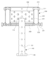
- KR
- South Korea
- Prior art keywords
- laser beam
- laser
- masking
- diameter
- welding apparatus
- Prior art date
- Legal status (The legal status is an assumption and is not a legal conclusion. Google has not performed a legal analysis and makes no representation as to the accuracy of the status listed.)
- Granted
Links
Images




Classifications
-
- B—PERFORMING OPERATIONS; TRANSPORTING
- B23—MACHINE TOOLS; METAL-WORKING NOT OTHERWISE PROVIDED FOR
- B23K—SOLDERING OR UNSOLDERING; WELDING; CLADDING OR PLATING BY SOLDERING OR WELDING; CUTTING BY APPLYING HEAT LOCALLY, e.g. FLAME CUTTING; WORKING BY LASER BEAM
- B23K26/00—Working by laser beam, e.g. welding, cutting or boring
- B23K26/20—Bonding
- B23K26/21—Bonding by welding
-
- B—PERFORMING OPERATIONS; TRANSPORTING
- B23—MACHINE TOOLS; METAL-WORKING NOT OTHERWISE PROVIDED FOR
- B23K—SOLDERING OR UNSOLDERING; WELDING; CLADDING OR PLATING BY SOLDERING OR WELDING; CUTTING BY APPLYING HEAT LOCALLY, e.g. FLAME CUTTING; WORKING BY LASER BEAM
- B23K26/00—Working by laser beam, e.g. welding, cutting or boring
- B23K26/02—Positioning or observing the workpiece, e.g. with respect to the point of impact; Aligning, aiming or focusing the laser beam
- B23K26/06—Shaping the laser beam, e.g. by masks or multi-focusing
- B23K26/064—Shaping the laser beam, e.g. by masks or multi-focusing by means of optical elements, e.g. lenses, mirrors or prisms
- B23K26/066—Shaping the laser beam, e.g. by masks or multi-focusing by means of optical elements, e.g. lenses, mirrors or prisms by using masks
Landscapes
- Physics & Mathematics (AREA)
- Optics & Photonics (AREA)
- Engineering & Computer Science (AREA)
- Plasma & Fusion (AREA)
- Mechanical Engineering (AREA)
- Laser Beam Processing (AREA)
Abstract
본 발명은 다양한 두께의 강판을 용접할 수 있는 레이저 용접 장치 및 레이저 용접 장치로 박판을 용접하는 방법을 제공하는 것으로 일실시예로서 레이저를 통하여, 두 부재를 용접하는 레이저 용접 장치이며, 레이저 빔을 생성하는 레이저 발생부; 및 상기 레이저 빔의 경로 상에 배치되며, 레이저 빔의 일부를 반사시킴으로써 레이저 빔의 직경을 감소시키는 마스킹부; 를 포함하는 레이저 용접 장치를 제공한다. The present invention provides a laser welding apparatus capable of welding a steel sheet of various thicknesses and a method of welding a thin plate with a laser welding apparatus. In one embodiment, a laser welding apparatus for welding two members through a laser, A laser generator for generating a laser beam; And a masking portion disposed on a path of the laser beam and reducing a diameter of the laser beam by reflecting a part of the laser beam; And a laser welding apparatus.
Description
본 발명은 레이저 용접 장치 및 레이저 용접 장치로 박판을 용접하는 방법에 대한 것으로, 다양한 두께의 강판의 용접이 가능한 레이어 용접 장치 및 레이저 용접 장치로 박판을 용접하는 방법에 대한 것이다.
The present invention relates to a laser welding apparatus and a method of welding a thin plate with a laser welding apparatus, and more particularly, to a layer welding apparatus capable of welding a steel plate of various thicknesses and a method of welding a thin plate with a laser welding apparatus.
레이저 용접 장치는 다양한 분야에서 사용되고 있으며, 특히, 코일로 권취된 강판을 풀어낸 후 연결하여 압연 등의 추가 공정을 수행하는데 사용되고 있다. The laser welding apparatus is used in various fields, and in particular, is used for unrolling a steel sheet wound by a coil and then performing an additional process such as rolling.
도 1 에는 종래의 레이저 용접 장치가 도시되어 있다. 도 1 에서 보이듯이, 종래의 용접 장치는 레이저 발생부(10)로부터 생성된 레이저 빔은 반사 거울(20)에서 반사되며 집광렌즈(30)을 통과하면서 소정의 집광경(D)으로 모여서 레이저 노즐(40)을 통과하여 소재(S)에 조사된다. 1 shows a conventional laser welding apparatus. 1, in the conventional welding apparatus, the laser beam generated from the
소재의 두께와 레이저 빔의 집광빔 직경은 양호한 용접부 형성에 있어서 상관관계가 있다. 즉, 소재의 두께가 얇을수록 레이저 빔의 집광빔 직경은 작아야하며, 가공 시에 소재 내부에 형성되는 레이저 키 홀의 직경이 두께보다 커서는 안된다. The thickness of the material and the diameter of the beam of condensation beam of the laser beam are correlated in forming good welds. That is, the thinner the thickness of the material, the smaller the diameter of the light beam of the laser beam, and the diameter of the laser keyhole formed in the material during processing should not be larger than the thickness.
레이저 제조사에서 만들어진 레이저의 발진기는 대체적으로 출력이 높을 수록 집광경이 높아지는 경향이 있으며, 통상 5kW 정도의 레이저 출력이라면 0.5~0.6mm 의 집광경을 가지고 있다. 이러한 집광경은 소재 두께가 0.6mm 이하에서 불량을 발생시키는 원인이 된다. 따라서, 0.6mm 이하 두께의 소재는 레이저 집광경이 적어도 0.6mm 이하가 되어야 양호한 용접이 가능하다.
Generally, a laser oscillator made by a laser manufacturer tends to have a higher condenser diameter as the output is higher. A laser output of about 5 kW typically has a condenser diameter of 0.5 to 0.6 mm. Such a condensing lens causes defects when the material thickness is 0.6 mm or less. Therefore, a material having a thickness of 0.6 mm or less can be welded satisfactorily when the laser condensing lens is at least 0.6 mm or less.
본 발명은 다양한 두께의 강판을 용접할 수 있는 레이저 용접 장치 및 레이저 용접 장치로 박판을 용접하는 방법을 제공하는 것을 목적으로 한다.
It is an object of the present invention to provide a laser welding apparatus capable of welding a steel sheet of various thicknesses and a method of welding a thin plate with a laser welding apparatus.
본 발명은 위와 같은 목적을 달성하기 위하여 다음과 같은 레이저 용접 장치 및 레이저 용접 장치로 박판을 용접하는 방법을 제공한다. The present invention provides a laser welding apparatus and a laser welding apparatus for welding a thin plate to achieve the above objects.
본 발명은 일실시예로서 레이저를 통하여, 두 부재를 용접하는 레이저 용접 장치이며, 레이저 빔을 생성하는 레이저 발생부; 및 상기 레이저 빔의 경로 상에 배치되며, 레이저 빔의 일부를 반사시킴으로써 레이저 빔의 직경을 감소시키는 마스킹부; 를 포함하는 레이저 용접 장치를 제공한다. According to an embodiment of the present invention, there is provided a laser welding apparatus for welding two members through a laser, comprising: a laser generator for generating a laser beam; And a masking portion disposed on a path of the laser beam and reducing a diameter of the laser beam by reflecting a part of the laser beam; And a laser welding apparatus.
본 발명의 일실시예는 반사된 레이저 빔을 감쇄시키도록 마스킹부에 인접하여 배치되는 감쇄부를 더 포함할 수도 있다. One embodiment of the present invention may further include an attenuator disposed adjacent to the masking portion to attenuate the reflected laser beam.
본 발명에서 상기 레이저 빔의 경로상에는 집광 렌즈가 배치되며, 상기 마스킹부는 상기 집광 렌즈를 통과한 레이저 빔이 통과하도록 배치될 수 있다. In the present invention, a condenser lens is disposed on the path of the laser beam, and the masking unit may be arranged to pass the laser beam passing through the condenser lens.
본 발명에서 상기 레이저 빔은 평행빔이며, 상기 집광 렌즈와 상기 레이저 발생부 사이에 반사 거울이 배치될 수 있다. In the present invention, the laser beam is a parallel beam, and a reflection mirror may be disposed between the condenser lens and the laser generating unit.
본 발명에서 상기 마스킹부는 레이져 노즐의 상부에 부착되며, 상기 감쇄부는 상기 마스킹부를 감싸며 배치될 수 있다. In the present invention, the masking portion is attached to the upper portion of the laser nozzle, and the attenuation portion is disposed to surround the masking portion.
또, 상기 감쇄부는 평면상에서 상기 마스킹부를 둘러싸되, 일부분은 개방되어 반사된 레이저 빔이 일 방향으로만 나오도록 구성될 수 있다. In addition, the attenuator may be configured such that the masking portion is surrounded on a plane, and a portion of the laser beam is opened so that the reflected laser beam exits only in one direction.
또한, 상기 마스킹부는 상기 레이저 노즐에 연결되는 연결부와 상기 연결부로부터 연장형성된 본체부; 상기 본체부의 단부에 형성된 마스킹면을 포함하며, 상기 본체부와 마스킹면에는 관통홀이 형성되어 상기 레이저빔이 통과하되, 상기 마스킹면의 관통홀의 직경은 상기 마스킹부를 통과하는 레이저 빔보다 작은 직경을 가질 수 있다. The masking portion may include a connecting portion connected to the laser nozzle and a main body extending from the connecting portion. Wherein a through hole is formed in the main body and the masking surface to allow the laser beam to pass therethrough and the diameter of the through hole of the masking surface is smaller than the diameter of the laser beam passing through the masking portion Lt; / RTI >
이때, 상기 본체부에는 반경방향으로 복수 개의 기체통과홀이 형성될 수 있다. At this time, a plurality of gas passing holes may be formed in the body portion in the radial direction.
또, 상기 마스킹면은 상기 레이저 빔의 조사 방향에 대하여 경사진 경사면으로 구성될 수 있다. The masking surface may be inclined with respect to the irradiation direction of the laser beam.
본 발명에서 상기 감쇄부는 구멍이 형성되어 있는 내면과 상기 내면으로부터 반경방향 외측으로 이격 배치되는 외면을 포함하여 구성될 수 있다.In the present invention, the attenuator may include an inner surface having a hole formed therein and an outer surface spaced radially outward from the inner surface.
본 발명은 레이저 용접 장치로 박판을 용접하는 방법으로, 레이져 노즐의 상부에 레이저 빔의 직경보다 작은 관통홀을 가지는 마스킹부를 부착하여, 레이저 빔의 일부를 외부로 반사시켜 레이저 빔의 직경을 감소시키는 차단 단계; 상기 차단 단계에서 반사된 레이저 빔을 감쇄시키거나 레이저광을 흡수하게하는 감쇄단계; 및 직경이 감소된 레이저 빔으로 두 부재를 용접하는 용접 단계;를 포함하는 레이저 용접 장치로 박판을 용접하는 방법을 제공한다. The present invention relates to a method of welding a thin plate with a laser welding apparatus, wherein a masking portion having a through hole smaller than the diameter of the laser beam is attached to the upper portion of the laser nozzle, and a part of the laser beam is reflected to the outside to reduce the diameter of the laser beam Blocking step; An attenuation step of attenuating or absorbing the laser beam reflected by the blocking step; And a welding step of welding the two members with a laser beam whose diameter is reduced. The present invention also provides a method of welding a thin plate with a laser welding apparatus.
본 발명에서 상기 감쇄단계는 레이저 빔의 일부는 감쇄시키며 동시에 일부는 흡수 부재를 통하여 흡수할 수 있다.
In the present invention, the attenuation step attenuates a part of the laser beam, and at the same time, a part of the laser beam can be absorbed through the absorptive member.
본 발명은 정해진 집광경을 가지는 레이저 용접 장치로 다양한 두께의 강판을 용접할 수 있으며, 특히 집광경 이하의 박판을 용접하는 방법을 제공할 수 있다.
According to the present invention, it is possible to weld a steel plate having various thicknesses by using a laser welding apparatus having a predetermined focusing mirror, and in particular, to provide a method of welding a thin plate having a diameter equal to or smaller than a collecting mirror.
도 1 은 종래의 레이저 용접 장치의 개략도이다.
도 2 는 본 발명의 레이저 용접 장치의 개략도이다.
도 3 은 본 발명의 레이저 용접 장치의 레이저 노즐 및 마스킹부의 사시도이다.
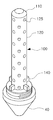
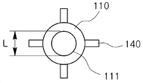
도 4a 및 b는 본 발명의 레이저 용접 장치의 마스킹부의 평면도 및 수직 단면도이다.
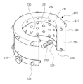
도 5 는 본 발명의 레이저 용접 장치의 감쇄부의 사시도이다.
도 6 은 본 발명의 레이저 용접 장치에서 감쇄부가 장착된 마스킹부의 수평 단면도이다.
도 7 은 본 발명의 레이저 용접 장치에서 감쇄부가 장착된 마스킹부의 수직 부분 단면도이다.
도 8 은 본 발명의 레이저 용접 장치에서 마스킹부에서 반사된 레이저 빔이 감쇄 및 반사되는 모습을 도시한 개략도이다. 1 is a schematic view of a conventional laser welding apparatus.
2 is a schematic view of the laser welding apparatus of the present invention.
3 is a perspective view of a laser nozzle and a masking portion of the laser welding apparatus of the present invention.
4A and 4B are a top view and a vertical cross-sectional view of the masking portion of the laser welding apparatus of the present invention.
5 is a perspective view of an attenuator of the laser welding apparatus of the present invention.
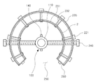
6 is a horizontal sectional view of a masking part equipped with an attenuation part in the laser welding apparatus of the present invention.
7 is a vertical cross-sectional view of a masking portion equipped with an attenuation portion in the laser welding apparatus of the present invention.
FIG. 8 is a schematic view showing a state in which a laser beam reflected by a masking part in the laser welding apparatus of the present invention is attenuated and reflected. FIG.
이하에서는 첨부된 도면을 참고로 하여 본 발명의 실시예를 중심으로 상세히 설명하도록 한다. Hereinafter, embodiments of the present invention will be described in detail with reference to the accompanying drawings.
도 2 에는 본 발명의 일실시예에 따른 레이저 용접 장치의 개략도가 도시되어 있다. 2 is a schematic diagram of a laser welding apparatus according to an embodiment of the present invention.
도 2 에서 보이듯이, 본 발명의 일실시예에 따른 레이저 용접 장치는 레이저 발생부(10), 레이저 발생부(10)에서 수평하게 발생된 레이저를 반사하는 반사 거울(20), 레이저 빔을 모으는 집광렌즈(30) 및 빔의 경로 상에 배치되어 집광렌즈(30)에 의해서 모인 레이저 빔이 레이저 노즐(40)을 통과한 후 소재(S)로 조사된다는 점에서는 종래의 레이저 용접 장치와 동일하다. 2, the laser welding apparatus according to an embodiment of the present invention includes a
하지만, 본 발명의 일실시예에 따른 레이저 용접 장치는 레이저 노즐(40)의 상부에서 상기 레이저 빔의 경로 상에 배치되어 집광렌즈를 통과하여 모이는 레이저 빔의 일부를 반사하는 마스킹부(100)와 마스킹부(100)에서 반사된 레이저 빔을 감쇠시키도록 마스킹부(100)에 인접하여 배치되는 감쇄부(200)를 더 포함한다.
However, the laser welding apparatus according to one embodiment of the present invention includes a
레이저 빔을 축소하기 위해서는 통상적으로 광학시스템을 변경한다. 즉 집광 렌즈(30)의 집광 거리가 보다 짧은 렌즈로 교체를 하면 레이저 빔의 집광경(D; 도 1 참고)이 작아진다. 또는 레이저 발생부(10)에서 나오는 평행빔의 직경을 크게 하게 되면 집광경이 작아진다. 이러한 2가지의 방법은 실제 생산 현장에서 몇 가지 문제를 가지고 있다. To reduce the laser beam, the optical system is usually changed. That is, if the
첫 번째 문제가 집광 거리가 짧아 지면 작업 거리가 변경이 되어 가공소재의 위치를 바꾸거나 집광렌즈(30)가 들어가 있는 레이저 헤드의 위치를 바꾸어야 하는데 이때 위치 정밀도가 저하되어 소재(S)의 용접부 형상이 달라지는 문제가 있다. 따라서 생산 현장에서는 가능한 한 위치 변경을 기피하는 경향이 있다. If the first problem is that the focusing distance is shortened, the working distance is changed to change the position of the workpiece or the position of the laser head in which the focusing
두 번째 문제는 레이저 발생부(10)에서 나오는 평행빔을 크게 하게 하기 위해서 광학 미러 등을 재조정 하여야 하는데 역시 정밀도의 재현성이 나빠진다. The second problem is that the optical mirror or the like must be readjusted in order to enlarge the parallel beam emitted from the
본 발명은 기존에 정확하게 장착이 된 광학시스템을 재조정하지 않고 집광빔을 작게 하는 방법을 제안하고 있으며, 이는 마스킹부(100)에 의해서 전송되는 레이저 빔을 중간에 마스킹(Masking)하여 레이저 빔의 직경을 강제적으로 줄일 수 있다. The present invention proposes a method of reducing a condensed beam without rearranging an optical system that has been correctly mounted. This is achieved by masking a laser beam transmitted by the
또한, 레이저 빔의 전송 도중에 마스킹부(100)를 활용하여 집광경 직경을 줄이기 위하여는 집광 렌즈(30)를 통과한 빔이 마스킹부(100)를 통과하게 하는 것이 가장 효과적이다. 만일 소재(S)에 가까운 위치라고 한다면 레이저 빔이 상당히 집광된 상태이기 때문에 에너지 밀도가 높다. 따라서 마스킹면(110; 도 3 내지 4 에서 후술함)에 손상이 될 우려가 있다. 반대로 집광렌즈(30)에 가까운 위치라고 한다면 마스킹면(110)에서 반사된 레이저 빔이 집광 렌즈(30)를 역으로 전송되어 레이저 발생부(10) 내부로 들어갈 수 있으며, 만일 레이저 발생부 내부로 반사광이 들어가는 경우, 반사광에 의해서 레이저 발생부가 손상될 우려가 있으며, 본 발명의 일실시예에서는 도 2 에 도시된 바와 같이 레이저 노즐(40)의 상측에 소정의 길이를 가지는 본체부(120; 도 3 및 4 에서 후술함)를 포함하는 마스킹부(100)를 배치한다.
In order to reduce the diameter of the condensing mirror by using the
도 3 에는 본 발명의 레이저 용접 장치의 레이저 노즐(40) 및 마스킹부(100)의 사시도가 도시되어 있으며, 도 4a 및 b 에는 본 발명의 레이저 용접 장치의 마스킹부(100)의 평면도 및 수직 단면도가 도시되어 있다. 3 is a perspective view of a
본 발명의 마스킹부(100)는 상기 레이저 노즐(40)에 연결되는 연결부(140)와 상기 연결부(140)로부터 연장형성된 본체부(120); 상기 본체부(120)의 단부에 형성된 마스킹면(110)을 포함하며, 상기 본체부(120)와 마스킹면(110)에는 관통홀(111, 121)이 형성되어 상기 레이저 빔이 통과하되, 상기 마스킹면(110)의 관통홀(111)의 직경(L)은 상기 마스킹부(100)를 통과하는 레이저 빔보다 작은 직경을 가진다. The
연결부(140)는 본체부(120)의 레이저 노즐(40)측 단부에 4면으로 연장하여 레이저 노즐(40)과 연결되는데, 레이저 노즐(40)과 연결될 수 있다면, 다른 구성을 가지는 것도 가능하다. 본체부(120)는 레이저 노즐(40)의 상부에서 상기 마스킹면(110)의 위치를 이격시키도록 소정의 길이로 연장하며, 내부에는 레이저 빔이 통과할 수 있는 관통홀(121)이 형성되어 있으며, 반경 방향으로는 기체통과홀(125)이 형성되어 있다. The connecting
반경 방향으로의 기체통과홀(125)이 형성되어 있어서, 레이저 조사 시의 불활성 가스가 잘 통할 수 있다. 또한, 본체부(120)의 길이는 레이저 빔의 마스킹 정도를 결정하는 것으로 집광 렌즈(30)를 통과하여 모이는 레이저 빔의 중간에 마스킹부(100)이 위치하고 있으므로, 본체부(120)의 길이가 길어질수록 더 많은 레이저 빔이 마스킹되므로, 더 작은 집광경(d; 도 2 참고)을 얻을 수 있다. The
마스킹면(110)은 본체부(120)에서 집광 렌즈(30)측 단부에 형성되어 있으며, 소정의 경사각을 가지는 경사면으로 형성되며, 상기 마스킹부(100)를 통과하는 레이저 빔보다 작은 직경을 가지는 관통홀(111)이 형성되어 있어서, 통과하는 레이저 빔의 일부는 경사면으로 형성된 마스킹면(110)에 의해서 외측으로 반사된다. 마스킹부의 재질은 레이저 빔에 대한 반사율이 높은 소재, 예를 들면 동을 사용하여야 한다.
The masking
도 5 에는 본 발명의 레이저 용접 장치의 감쇄부(200)의 사시도가 도시되어 있으며, 도 6 에는 본 발명의 레이저 용접 장치에서 감쇄부(200)가 장착된 마스킹부(100)의 수평 단면도가 도시되어 있으며, 도 7 에는 본 발명의 레이저 용접 장치에서 감쇄부(200)가 장착된 마스킹부(100)의 수직 부분 단면도가 도시되어 있다. FIG. 5 is a perspective view of the
감쇄부(200)는 레이저 빔의 일부가 통과하도록 구멍(232)이 형성되어 있는 내면(231)과 상기 내면으로부터 레이저 빔의 경로를 중심축으로 봤을 때 반경방향 외측으로 이격 배치되는 외면(235)을 포함하는 본체부(230); 본체부 상측 및 하측에서 상기 내면(231) 및 외면(235)를 커버하는 상부커버(210)와 하부커버(220); 상기 본체부(230)의 내면(231) 및 외면(235)의 측면을 커버하는 측면커버(260)를 포함하며, 각 커버에는 본체부(230)와의 결합을 위한 결합수단(211, 221, 261)이 구비된다. The
또한, 하부커버(220)에는 상기 마스킹부(100)와 연결을 위하여 볼트 형식으로 구현된 마스킹 연결부(240)가 구비된다. 마스킹 연결부(240)는 상기 마스킹부(100)를 중심으로 양측에 하나씩 구비되어, 감쇄부(200)의 하면이 마스킹부(100)의 적어도 마스킹면(111)보다 낮은 위치에 위치하도록 마스킹부(100)와 감쇄부(200)를 정렬하게 한다. In addition, the
한편, 도 6 에서 보이듯이, 감쇄부(200)의 본체부(230)는 레이저 빔의 경로 중심을 기준으로 일부가 개방된 개방부(250)를 가지는 원호형으로 구성된다. 즉, 상기 마스킹부(100)에서 반사된 레이저 빔의 전부가 감쇄부(200)에서 반사되는 것은 아니며, 일부는 감쇄부(200)로 향하고 일부는 레이저 빔에 노출되더라도 문제가 없는 흡수부(300; 도 8참고)로 향하며, 감쇄부(200)로 향한 레이저 빔도 감쇄부(200)에서 감쇄되거나 반사에 의해서 흡수부(300; 도 8 참고)로 향하게 된다. 감쇄부(200)의 본체부(230)가 형성하는 원호는 대략 270도 정도이나, 이에 제한되는 것은 아니며, 흡수부(300; 도 8 참고)의 영역에 따라서 달라질 수 있다.
6, the
도 8 에는 본 발명의 레이저 용접 장치에서 마스킹부에서 반사된 레이저 빔이 감쇄 및 반사되는 모습을 도시한 개략도가 도시되어 있다. FIG. 8 is a schematic view showing a state in which a laser beam reflected by a masking portion in a laser welding apparatus according to the present invention is attenuated and reflected.
도 8 에서 보이듯이, 본 발명에서 집광 렌즈(30)를 통과한 레이저 빔의 일부는 마스킹부(100)의 상부에 경사면으로 형성된 마스킹면(110)에 의해서 종전의 레이저 빔 경로에서 벗어나 외측으로 반사되며, 일부는 흡수부(300)로, 나머지는 상기 마스킹부(100)의 일부 면을 둘러싸고 있는 감쇄부(200)로 향한다. 8, in the present invention, a part of the laser beam passing through the condensing
감쇄부(200)로 향한 레이저 빔의 일부(l1, l2)는 내면(231)에 반사되다가 감쇄부(200)를 빠져나가 흡수부(300)를 향하게 되며, 감쇄부(200)로 향한 레이저 빔의 다른 일부는 감쇄부(200)에서 반사되다가 혹은 바로 감쇄부(200)의 내면(231)에 형성된 구멍(232)로 들어가 내면(231)과 외면(232) 사이에서 반사되면서 감쇄된다. A portion of the laser beam 11 directed to the
본 발명에서 감쇄부(200)는 반사된 레이저 빔을 다시 반사시키면서 흡수부(300)와 같이 레이저 빔을 받아 줄 수 있는 부분으로 유도하는 수단 혹은 반사시키면서 레이저 빔 자체를 감쇄시키는 수단을 의미하는 것이며, 반사가 되더라도 레이저 빔의 감쇄가 일어난다면 본 발명에서 의미하는 감쇄부(200)라고 할 수 있다. In the present invention, the
감쇄부(200) 역시 마스킹부와 동일하게 레이저 빔에 대한 반사율이 높은 소재, 예를 들면 동을 사용하는 것이 바람직하다.
The
본 발명은 광학 시스템의 변화 없이 레이저 빔의 집광경을 감소시키는 마스킹부 및 감쇄부를 포함하며, 그에 의해서 광학 시스템 없이도 두께가 두꺼운 소재부터 두께가 광확 시스템의 집광경 직경보다 작은 소재까지 다양한 두께의 소재를 양호한 품질로 용접하는 것이 가능하다. The present invention includes a masking portion and an attenuating portion for reducing a focusing point of a laser beam without changing the optical system so that a material having various thicknesses ranging from a material having a thick thickness to a material having a thickness smaller than the diameter of a focusing lens It is possible to weld with quality.
또한, 하나의 장비로 다양한 두께의 소재를 용접할 수 있을 뿐만 아니라 한번 설정된 광학시스템을 변화없이 계속 사용할 수 있어서, 작업 효율성 및 품질 확보도 가능하며, 추가 설비의 부담이 없어서 비용의 절감도 가능하다.
In addition, it is possible not only to weld various thickness materials with one equipment, but also to use the set optical system continuously without change, and it is possible to secure work efficiency and quality, .
10: 레이저 발생부
20: 반사 거울
30: 집광 렌즈
40: 레이저 노즐
100: 마스킹부
110: 마스킹면
120: 본체부
140: 연결부
200: 감쇄부
210: 상부커버
220: 하부커버
230: 본체부
240: 마스킹 연결부
260: 측면커버10: laser generator 20: reflective mirror
30: condenser lens 40: laser nozzle
100: masking portion 110: masking surface
120: main body part 140:
200: attenuator 210: upper cover
220: lower cover 230:
240: masking connection 260: side cover
Claims (12)
레이저 빔을 생성하는 레이저 발생부; 및
상기 레이저 빔의 경로 상에 배치되며, 레이저 빔의 일부를 반사시킴으로써 레이저 빔의 직경을 감소시키는 마스킹부; 를 포함하는 레이저 용접 장치.
A laser welding apparatus for welding two members through a laser,
A laser generator for generating a laser beam; And
A masking unit disposed on a path of the laser beam and reducing a diameter of the laser beam by reflecting a part of the laser beam; The laser welding apparatus comprising:
반사된 레이저 빔을 감쇄시키도록 마스킹부에 인접하여 배치되는 감쇄부를 더 포함하는 것을 특징으로 하는 레이저 용접 장치.
The method according to claim 1,
Further comprising an attenuation portion disposed adjacent to the masking portion to attenuate the reflected laser beam.
상기 레이저 빔의 경로상에는 집광 렌즈가 배치되며,
상기 마스킹부는 상기 집광 렌즈를 통과한 레이저 빔이 통과하도록 배치되는 것을 특징으로 하는 레이저 용접 장치.3. The method of claim 2,
A focusing lens is disposed on the path of the laser beam,
Wherein the masking portion is disposed so that a laser beam passed through the condensing lens passes through the masking portion.
상기 레이저 빔은 평행빔이며,
상기 집광 렌즈와 상기 레이저 발생부 사이에 반사 거울이 배치되는 것을 특징으로 하는 레이저 용접 장치. The method of claim 3,
The laser beam is a parallel beam,
And a reflective mirror is disposed between the condenser lens and the laser generating unit.
상기 마스킹부는 레이져 노즐의 상부에 부착되며,
상기 감쇄부는 상기 마스킹부를 감싸며 배치되는 것을 특징으로 하는 레이저 용접 장치.5. The method according to any one of claims 1 to 4,
Wherein the masking portion is attached to an upper portion of the laser nozzle,
Wherein the attenuator is disposed to surround the masking portion.
상기 감쇄부는 평면상에서 상기 마스킹부를 둘러싸되, 일부분은 개방되어 반사된 레이저 빔이 일 방향으로만 나오도록 구성되는 것을 특징으로 하는 레이저 용접 장치.6. The method of claim 5,
Wherein the attenuator is configured such that the masking portion is surrounded on a plane and a part of the attenuator is opened so that the reflected laser beam exits only in one direction.
상기 마스킹부는 상기 레이저 노즐에 연결되는 연결부와 상기 연결부로부터 연장형성된 본체부; 상기 본체부의 단부에 형성된 마스킹면을 포함하며,
상기 본체부와 마스킹면에는 관통홀이 형성되어 상기 레이저빔이 통과하되, 상기 마스킹면의 관통홀의 직경은 상기 마스킹부를 통과하는 레이저 빔보다 작은 직경을 가지는 것을 특징으로 하는 레이저 용접 장치. 6. The method of claim 5,
Wherein the masking portion includes a connection portion connected to the laser nozzle and a body portion extending from the connection portion; And a masking surface formed at an end of the body portion,
Wherein a through hole is formed in the main body and the masking surface to allow the laser beam to pass therethrough and the diameter of the through hole of the masking surface is smaller than the diameter of the laser beam passing through the masking portion.
상기 본체부에는 반경방향으로 복수 개의 기체통과홀이 형성되는 것을 특징으로 하는 레이저 용접 장치. 8. The method of claim 7,
Wherein a plurality of gas through holes are formed in the body portion in the radial direction.
상기 마스킹면은 상기 레이저 빔의 조사 방향에 대하여 경사진 경사면으로 구성되는 것을 특징으로 하는 레이저 용접 장치. 8. The method of claim 7,
Wherein the masking surface comprises an inclined surface inclined with respect to an irradiation direction of the laser beam.
상기 감쇄부는 구멍이 형성되어 있는 내면과 상기 내면으로부터 반경방향 외측으로 이격 배치되는 외면을 포함하여 구성되는 것을 특징으로 하는 레이저 용접 장치. The method according to claim 6,
Wherein the attenuator comprises an inner surface having a hole formed therein and an outer surface spaced radially outward from the inner surface.
레이져 노즐의 상부에 레이저 빔의 직경보다 작은 관통홀을 가지는 마스킹부를 부착하여, 레이저 빔의 일부를 외부로 반사시켜 레이저 빔의 직경을 감소시키는 차단 단계;
상기 차단 단계에서 반사된 레이저 빔을 감쇄시키거나 레이저광을 흡수하게하는 감쇄단계; 및
직경이 감소된 레이저 빔으로 두 부재를 용접하는 용접 단계;를 포함하는 레이저 용접 장치로 박판을 용접하는 방법.As a method of welding a thin plate with a laser welding apparatus,
A blocking step of attaching a masking part having a through hole smaller in diameter than the diameter of the laser beam to the upper part of the laser nozzle to reduce a diameter of the laser beam by reflecting a part of the laser beam to the outside;
An attenuation step of attenuating or absorbing the laser beam reflected by the blocking step; And
And a welding step of welding the two members with a reduced diameter laser beam.
상기 감쇄단계는 레이저 빔의 일부는 감쇄시키며 동시에 일부는 흡수 부재를 통하여 흡수하는 것을 특징으로 하는 레이저 용접 장치로 박판을 용접하는 방법.
12. The method of claim 11,
Wherein the attenuating step attenuates a portion of the laser beam while partially absorbing the laser beam through the absorptive member.
Priority Applications (1)
| Application Number | Priority Date | Filing Date | Title |
|---|---|---|---|
| KR1020140186543A KR101684485B1 (en) | 2014-12-22 | 2014-12-22 | Laser Welding Device and Welding Method of Thin Plate Using Laser Welding Device |
Applications Claiming Priority (1)
| Application Number | Priority Date | Filing Date | Title |
|---|---|---|---|
| KR1020140186543A KR101684485B1 (en) | 2014-12-22 | 2014-12-22 | Laser Welding Device and Welding Method of Thin Plate Using Laser Welding Device |
Publications (2)
| Publication Number | Publication Date |
|---|---|
| KR20160077382A true KR20160077382A (en) | 2016-07-04 |
| KR101684485B1 KR101684485B1 (en) | 2016-12-09 |
Family
ID=56500838
Family Applications (1)
| Application Number | Title | Priority Date | Filing Date |
|---|---|---|---|
| KR1020140186543A Active KR101684485B1 (en) | 2014-12-22 | 2014-12-22 | Laser Welding Device and Welding Method of Thin Plate Using Laser Welding Device |
Country Status (1)
| Country | Link |
|---|---|
| KR (1) | KR101684485B1 (en) |
Cited By (1)
| Publication number | Priority date | Publication date | Assignee | Title |
|---|---|---|---|---|
| CN108672929A (en) * | 2018-07-16 | 2018-10-19 | 内蒙古第机械集团股份有限公司 | A kind of method for laser welding of super high strength armour steel |
Families Citing this family (1)
| Publication number | Priority date | Publication date | Assignee | Title |
|---|---|---|---|---|
| KR102935544B1 (en) | 2023-11-01 | 2026-03-05 | 국립공주대학교 산학협력단 | Laser Edge Welding Method Using A Gap |
Citations (4)
| Publication number | Priority date | Publication date | Assignee | Title |
|---|---|---|---|---|
| JPH10235484A (en) * | 1997-02-24 | 1998-09-08 | Mitsubishi Electric Corp | Laser processing equipment |
| JP2000254792A (en) * | 1999-03-10 | 2000-09-19 | Sumitomo Heavy Ind Ltd | Emission optical system for laser beam machine |
| JP2000280086A (en) * | 1999-03-30 | 2000-10-10 | Hitachi Via Mechanics Ltd | Laser processing machine |
| JP2003305584A (en) * | 2002-04-11 | 2003-10-28 | Mitsubishi Electric Corp | Laser processing head of laser processing equipment |
-
2014
- 2014-12-22 KR KR1020140186543A patent/KR101684485B1/en active Active
Patent Citations (4)
| Publication number | Priority date | Publication date | Assignee | Title |
|---|---|---|---|---|
| JPH10235484A (en) * | 1997-02-24 | 1998-09-08 | Mitsubishi Electric Corp | Laser processing equipment |
| JP2000254792A (en) * | 1999-03-10 | 2000-09-19 | Sumitomo Heavy Ind Ltd | Emission optical system for laser beam machine |
| JP2000280086A (en) * | 1999-03-30 | 2000-10-10 | Hitachi Via Mechanics Ltd | Laser processing machine |
| JP2003305584A (en) * | 2002-04-11 | 2003-10-28 | Mitsubishi Electric Corp | Laser processing head of laser processing equipment |
Cited By (1)
| Publication number | Priority date | Publication date | Assignee | Title |
|---|---|---|---|---|
| CN108672929A (en) * | 2018-07-16 | 2018-10-19 | 内蒙古第机械集团股份有限公司 | A kind of method for laser welding of super high strength armour steel |
Also Published As
| Publication number | Publication date |
|---|---|
| KR101684485B1 (en) | 2016-12-09 |
Similar Documents
| Publication | Publication Date | Title |
|---|---|---|
| US20230030159A1 (en) | Methods and laser welding devices for deep welding a workpiece | |
| KR101004497B1 (en) | Apparatus comprising a beam forming unit for inducing radiant energy into a material composed of a low absorbing material | |
| JP4514767B2 (en) | Laser energy measuring device and laser processing device | |
| KR100584310B1 (en) | Method and apparatus for processing material with laser beam injected into injection liquid | |
| US6710283B2 (en) | Laser weld quality monitoring method and system | |
| JP5671873B2 (en) | Laser welding monitoring device | |
| RU2638140C2 (en) | Welding device with quality control of weld structure and welding method with quality control of weld structure | |
| CN103228400B (en) | For the method and apparatus of the Materialbearbeitung mit Laserlicht of workpiece | |
| KR20160101064A (en) | Stacked transparent material cutting with ultrafast laser beam optics, disruptive layers and other layers | |
| KR100259969B1 (en) | Method and apparatus for strengthening all field mask investigation | |
| CN109207713A (en) | A kind of laser shock peening method of part corner regions | |
| KR101195602B1 (en) | Laser cutting apparatus capable of cutting workpiece having multi layer | |
| WO2023058504A1 (en) | Beamforming device | |
| US20060186098A1 (en) | Method and apparatus for laser processing | |
| KR101684485B1 (en) | Laser Welding Device and Welding Method of Thin Plate Using Laser Welding Device | |
| US20120085740A1 (en) | Device for simultaneously processing the circumference of a workpiece with laser beams | |
| JPH0729210B2 (en) | Laser welding method | |
| JP2000275568A (en) | Beam mode converting optical system | |
| CN101223628B (en) | Method of suppressing distortion of a working laser beam of a laser link processing system | |
| JP2012223772A (en) | Laser processing device | |
| JP2000227576A (en) | Emission optical system for laser processing device | |
| TW202422117A (en) | Rotationally symmetrical curved beam dump for conical beams | |
| JP2005186099A (en) | Laser beam machining device and method | |
| JPS60244495A (en) | Laser beam machine | |
| JP2000176667A (en) | Laser welding monitoring system |
Legal Events
| Date | Code | Title | Description |
|---|---|---|---|
| A201 | Request for examination | ||
| PA0109 | Patent application |
St.27 status event code: A-0-1-A10-A12-nap-PA0109 |
|
| PA0201 | Request for examination |
St.27 status event code: A-1-2-D10-D11-exm-PA0201 |
|
| D13-X000 | Search requested |
St.27 status event code: A-1-2-D10-D13-srh-X000 |
|
| D14-X000 | Search report completed |
St.27 status event code: A-1-2-D10-D14-srh-X000 |
|
| E902 | Notification of reason for refusal | ||
| PE0902 | Notice of grounds for rejection |
St.27 status event code: A-1-2-D10-D21-exm-PE0902 |
|
| E13-X000 | Pre-grant limitation requested |
St.27 status event code: A-2-3-E10-E13-lim-X000 |
|
| P11-X000 | Amendment of application requested |
St.27 status event code: A-2-2-P10-P11-nap-X000 |
|
| P13-X000 | Application amended |
St.27 status event code: A-2-2-P10-P13-nap-X000 |
|
| PG1501 | Laying open of application |
St.27 status event code: A-1-1-Q10-Q12-nap-PG1501 |
|
| E90F | Notification of reason for final refusal | ||
| PE0902 | Notice of grounds for rejection |
St.27 status event code: A-1-2-D10-D21-exm-PE0902 |
|
| P11-X000 | Amendment of application requested |
St.27 status event code: A-2-2-P10-P11-nap-X000 |
|
| P13-X000 | Application amended |
St.27 status event code: A-2-2-P10-P13-nap-X000 |
|
| R18-X000 | Changes to party contact information recorded |
St.27 status event code: A-3-3-R10-R18-oth-X000 |
|
| E701 | Decision to grant or registration of patent right | ||
| PE0701 | Decision of registration |
St.27 status event code: A-1-2-D10-D22-exm-PE0701 |
|
| GRNT | Written decision to grant | ||
| PR0701 | Registration of establishment |
St.27 status event code: A-2-4-F10-F11-exm-PR0701 |
|
| PR1002 | Payment of registration fee |
St.27 status event code: A-2-2-U10-U11-oth-PR1002 Fee payment year number: 1 |
|
| PG1601 | Publication of registration |
St.27 status event code: A-4-4-Q10-Q13-nap-PG1601 |
|
| R18-X000 | Changes to party contact information recorded |
St.27 status event code: A-5-5-R10-R18-oth-X000 |
|
| PR1001 | Payment of annual fee |
St.27 status event code: A-4-4-U10-U11-oth-PR1001 Fee payment year number: 4 |
|
| PR1001 | Payment of annual fee |
St.27 status event code: A-4-4-U10-U11-oth-PR1001 Fee payment year number: 5 |
|
| R18-X000 | Changes to party contact information recorded |
St.27 status event code: A-5-5-R10-R18-oth-X000 |
|
| PR1001 | Payment of annual fee |
St.27 status event code: A-4-4-U10-U11-oth-PR1001 Fee payment year number: 6 |
|
| PR1001 | Payment of annual fee |
St.27 status event code: A-4-4-U10-U11-oth-PR1001 Fee payment year number: 7 |
|
| PR1001 | Payment of annual fee |
St.27 status event code: A-4-4-U10-U11-oth-PR1001 Fee payment year number: 8 |
|
| R18-X000 | Changes to party contact information recorded |
St.27 status event code: A-5-5-R10-R18-oth-X000 |
|
| PR1001 | Payment of annual fee |
St.27 status event code: A-4-4-U10-U11-oth-PR1001 Fee payment year number: 9 |
|
| PR1001 | Payment of annual fee |
St.27 status event code: A-4-4-U10-U11-oth-PR1001 Fee payment year number: 10 |
|
| U11 | Full renewal or maintenance fee paid |
Free format text: ST27 STATUS EVENT CODE: A-4-4-U10-U11-OTH-PR1001 (AS PROVIDED BY THE NATIONAL OFFICE) Year of fee payment: 10 |
|
| R18 | Changes to party contact information recorded |
Free format text: ST27 STATUS EVENT CODE: A-5-5-R10-R18-OTH-X000 (AS PROVIDED BY THE NATIONAL OFFICE) |
|
| R18-X000 | Changes to party contact information recorded |
St.27 status event code: A-5-5-R10-R18-oth-X000 |