KR20160092995A - Magnetic bearing device and vacuum pump - Google Patents
Magnetic bearing device and vacuum pump Download PDFInfo
- Publication number
- KR20160092995A KR20160092995A KR1020167012128A KR20167012128A KR20160092995A KR 20160092995 A KR20160092995 A KR 20160092995A KR 1020167012128 A KR1020167012128 A KR 1020167012128A KR 20167012128 A KR20167012128 A KR 20167012128A KR 20160092995 A KR20160092995 A KR 20160092995A
- Authority
- KR
- South Korea
- Prior art keywords
- current
- magnetic bearing
- command value
- electromagnets
- gain
- Prior art date
- Legal status (The legal status is an assumption and is not a legal conclusion. Google has not performed a legal analysis and makes no representation as to the accuracy of the status listed.)
- Granted
Links
Images


Classifications
-
- F—MECHANICAL ENGINEERING; LIGHTING; HEATING; WEAPONS; BLASTING
- F04—POSITIVE - DISPLACEMENT MACHINES FOR LIQUIDS; PUMPS FOR LIQUIDS OR ELASTIC FLUIDS
- F04D—NON-POSITIVE-DISPLACEMENT PUMPS
- F04D29/00—Details, component parts, or accessories
- F04D29/05—Shafts or bearings, or assemblies thereof, specially adapted for elastic fluid pumps
- F04D29/056—Bearings
- F04D29/058—Bearings magnetic; electromagnetic
-
- F—MECHANICAL ENGINEERING; LIGHTING; HEATING; WEAPONS; BLASTING
- F16—ENGINEERING ELEMENTS AND UNITS; GENERAL MEASURES FOR PRODUCING AND MAINTAINING EFFECTIVE FUNCTIONING OF MACHINES OR INSTALLATIONS; THERMAL INSULATION IN GENERAL
- F16C—SHAFTS; FLEXIBLE SHAFTS; ELEMENTS OR CRANKSHAFT MECHANISMS; ROTARY BODIES OTHER THAN GEARING ELEMENTS; BEARINGS
- F16C32/00—Bearings not otherwise provided for
- F16C32/04—Bearings not otherwise provided for using magnetic or electric supporting means
- F16C32/0406—Magnetic bearings
- F16C32/044—Active magnetic bearings
- F16C32/0444—Details of devices to control the actuation of the electromagnets
- F16C32/0451—Details of controllers, i.e. the units determining the power to be supplied, e.g. comparing elements, feedback arrangements with P.I.D. control
-
- F—MECHANICAL ENGINEERING; LIGHTING; HEATING; WEAPONS; BLASTING
- F04—POSITIVE - DISPLACEMENT MACHINES FOR LIQUIDS; PUMPS FOR LIQUIDS OR ELASTIC FLUIDS
- F04D—NON-POSITIVE-DISPLACEMENT PUMPS
- F04D19/00—Axial-flow pumps
- F04D19/02—Multi-stage pumps
- F04D19/04—Multi-stage pumps specially adapted to the production of a high vacuum, e.g. molecular pumps
- F04D19/042—Turbomolecular vacuum pumps
-
- F—MECHANICAL ENGINEERING; LIGHTING; HEATING; WEAPONS; BLASTING
- F04—POSITIVE - DISPLACEMENT MACHINES FOR LIQUIDS; PUMPS FOR LIQUIDS OR ELASTIC FLUIDS
- F04D—NON-POSITIVE-DISPLACEMENT PUMPS
- F04D27/00—Control, e.g. regulation, of pumps, pumping installations or pumping systems specially adapted for elastic fluids
-
- F—MECHANICAL ENGINEERING; LIGHTING; HEATING; WEAPONS; BLASTING
- F04—POSITIVE - DISPLACEMENT MACHINES FOR LIQUIDS; PUMPS FOR LIQUIDS OR ELASTIC FLUIDS
- F04D—NON-POSITIVE-DISPLACEMENT PUMPS
- F04D29/00—Details, component parts, or accessories
- F04D29/04—Shafts or bearings, or assemblies thereof
- F04D29/046—Bearings
- F04D29/048—Bearings magnetic; electromagnetic
-
- F—MECHANICAL ENGINEERING; LIGHTING; HEATING; WEAPONS; BLASTING
- F04—POSITIVE - DISPLACEMENT MACHINES FOR LIQUIDS; PUMPS FOR LIQUIDS OR ELASTIC FLUIDS
- F04D—NON-POSITIVE-DISPLACEMENT PUMPS
- F04D29/00—Details, component parts, or accessories
- F04D29/05—Shafts or bearings, or assemblies thereof, specially adapted for elastic fluid pumps
- F04D29/053—Shafts
-
- F—MECHANICAL ENGINEERING; LIGHTING; HEATING; WEAPONS; BLASTING
- F16—ENGINEERING ELEMENTS AND UNITS; GENERAL MEASURES FOR PRODUCING AND MAINTAINING EFFECTIVE FUNCTIONING OF MACHINES OR INSTALLATIONS; THERMAL INSULATION IN GENERAL
- F16C—SHAFTS; FLEXIBLE SHAFTS; ELEMENTS OR CRANKSHAFT MECHANISMS; ROTARY BODIES OTHER THAN GEARING ELEMENTS; BEARINGS
- F16C32/00—Bearings not otherwise provided for
- F16C32/04—Bearings not otherwise provided for using magnetic or electric supporting means
- F16C32/0406—Magnetic bearings
- F16C32/044—Active magnetic bearings
- F16C32/0474—Active magnetic bearings for rotary movement
- F16C32/0489—Active magnetic bearings for rotary movement with active support of five degrees of freedom, e.g. two radial magnetic bearings combined with an axial bearing
-
- H—ELECTRICITY
- H02—GENERATION; CONVERSION OR DISTRIBUTION OF ELECTRIC POWER
- H02K—DYNAMO-ELECTRIC MACHINES
- H02K7/00—Arrangements for handling mechanical energy structurally associated with dynamo-electric machines, e.g. structural association with mechanical driving motors or auxiliary dynamo-electric machines
- H02K7/08—Structural association with bearings
- H02K7/09—Structural association with bearings with magnetic bearings
-
- F—MECHANICAL ENGINEERING; LIGHTING; HEATING; WEAPONS; BLASTING
- F16—ENGINEERING ELEMENTS AND UNITS; GENERAL MEASURES FOR PRODUCING AND MAINTAINING EFFECTIVE FUNCTIONING OF MACHINES OR INSTALLATIONS; THERMAL INSULATION IN GENERAL
- F16C—SHAFTS; FLEXIBLE SHAFTS; ELEMENTS OR CRANKSHAFT MECHANISMS; ROTARY BODIES OTHER THAN GEARING ELEMENTS; BEARINGS
- F16C2231/00—Running-in; Initial operation
-
- F—MECHANICAL ENGINEERING; LIGHTING; HEATING; WEAPONS; BLASTING
- F16—ENGINEERING ELEMENTS AND UNITS; GENERAL MEASURES FOR PRODUCING AND MAINTAINING EFFECTIVE FUNCTIONING OF MACHINES OR INSTALLATIONS; THERMAL INSULATION IN GENERAL
- F16C—SHAFTS; FLEXIBLE SHAFTS; ELEMENTS OR CRANKSHAFT MECHANISMS; ROTARY BODIES OTHER THAN GEARING ELEMENTS; BEARINGS
- F16C2233/00—Monitoring condition, e.g. temperature, load, vibration
-
- F—MECHANICAL ENGINEERING; LIGHTING; HEATING; WEAPONS; BLASTING
- F16—ENGINEERING ELEMENTS AND UNITS; GENERAL MEASURES FOR PRODUCING AND MAINTAINING EFFECTIVE FUNCTIONING OF MACHINES OR INSTALLATIONS; THERMAL INSULATION IN GENERAL
- F16C—SHAFTS; FLEXIBLE SHAFTS; ELEMENTS OR CRANKSHAFT MECHANISMS; ROTARY BODIES OTHER THAN GEARING ELEMENTS; BEARINGS
- F16C2300/00—Application independent of particular apparatuses
- F16C2300/30—Application independent of particular apparatuses related to direction with respect to gravity
-
- F—MECHANICAL ENGINEERING; LIGHTING; HEATING; WEAPONS; BLASTING
- F16—ENGINEERING ELEMENTS AND UNITS; GENERAL MEASURES FOR PRODUCING AND MAINTAINING EFFECTIVE FUNCTIONING OF MACHINES OR INSTALLATIONS; THERMAL INSULATION IN GENERAL
- F16C—SHAFTS; FLEXIBLE SHAFTS; ELEMENTS OR CRANKSHAFT MECHANISMS; ROTARY BODIES OTHER THAN GEARING ELEMENTS; BEARINGS
- F16C2360/00—Engines or pumps
- F16C2360/44—Centrifugal pumps
- F16C2360/45—Turbo-molecular pumps
Landscapes
- Engineering & Computer Science (AREA)
- General Engineering & Computer Science (AREA)
- Mechanical Engineering (AREA)
- Physics & Mathematics (AREA)
- Electromagnetism (AREA)
- Power Engineering (AREA)
- Magnetic Bearings And Hydrostatic Bearings (AREA)
- Non-Positive Displacement Air Blowers (AREA)
Abstract
초기 조정이 간단하며, 제어 기기의 메모리 용량을 늘리지 않고, 간단한 알고리즘으로 최적의 베어링 제어를 행할 수 있는 자기 베어링 장치를 제공한다.
한 쌍의 제곱기(32xp, 32xm), 및 가산기(33)가, 도시하지 않는 자기 베어링의 로터축을 래디얼 방향으로 반대 방향으로 서로 끌어당기는 한 쌍의 전자석의 각 전류 정상치(Ip, Im)를 취득하고, 각각 제곱화하여 가산한다. 그리고, 자기 베어링의 부착 자세에 따라 각 전자석의 전류를 최적으로 변화시키기 위해, 보정 계수 연산기(35)가, 제곱·가산된 전류 정상치(Ip^2+Im^2)로부터 전자석에 작용하는 보정 게인 지령치 Kcomp를 계산한다. 다음에, 전자석의 제어 회로의 기본 게인 Kctrl에 보정 게인 지령치 Kcomp를 가산한 게인 지령치 G를 게인 앰프(38)로 입력한다. 게인 앰프(38)는, 게인 지령치 G에 의거하여, 보정된 전류 지령치를 생성하여, 자기 베어링을 최적으로 제어한다. Provided is a magnetic bearing device which is simple in initial adjustment and capable of performing optimum bearing control with a simple algorithm without increasing the memory capacity of the control device.
The pair of squarers 32xp and 32xm and the adder 33 acquire the respective current normal values Ip and Im of the pair of electromagnets pulling the rotor shaft of the magnetic bearing not shown in the opposite direction in the radial direction from each other And each of them is squared and added. In order to optimally change the currents of the respective electromagnets according to the mounting posture of the magnetic bearings, the correction coefficient calculator 35 calculates the correction gain (Ip ^ 2 + Im ^ 2) Calculate the command value Kcomp. Next, the gain command value G obtained by adding the correction gain command value Kcomp to the basic gain Kctrl of the control circuit of the electromagnet is input to the gain amplifier 38. [ The gain amplifier 38 generates a corrected current command value based on the gain command value G to optimally control the magnetic bearing.

Description
본 발명은, 전자석의 전자력에 의해 회전체를 비접촉으로 지지하는 자기 베어링과, 그 자기 베어링을 제어하는 제어 기기를 구비한 자기 베어링 장치, 및 그 자기 베어링 장치를 이용한 진공 펌프에 관한 것이다. Field of the Invention [0002] The present invention relates to a magnetic bearing device having a magnetic bearing for supporting a rotating body in a noncontact manner by an electromagnetic force of an electromagnet, a control device for controlling the magnetic bearing, and a vacuum pump using the magnetic bearing device.
종래부터, 회전체(강체)가 가지는 6자유도 중 5자유도를 전자석의 전자력(흡인력)으로 지지하는 자기 베어링(5축 제어 자기 베어링)이 널리 알려져 있다. 이러한 자기 베어링은, 베어링 부분이 비접촉이기 때문에 마모가 없어 장수명이며, 베어링 손실이 미소하기 때문에 초고속 회전 기기에 적용이 가능하고, 또한, 베어링의 강성·감쇠 특성을 임의로 조정할 수 있어, 저진동·저소음 회전이 가능한 등, 우수한 성능을 구비하고 있다. 따라서, 이러한 자기 베어링은, 예를 들면, 반도체 제조 장치 등에 이용되는 진공 펌프, 터보 분자 펌프, 및 터빈 발전기, 공작기계 등에 이용되고 있다. BACKGROUND ART [0002] A magnetic bearing (5-axis control magnetic bearing) for holding 5 degrees of freedom among 6 degrees of freedom of a rotating body (rigid body) by electromagnetic force (attracting force) of an electromagnet is widely known. Such a magnetic bearing can be applied to an ultra high-speed rotating machine since the bearing portion is not in contact with the bearing due to its long life due to its non-contact, and its bearing loss is minute, and the rigidity and damping characteristics of the bearing can be arbitrarily adjusted, And the like. Therefore, such magnetic bearings are used, for example, in vacuum pumps, turbo-molecular pumps, turbine generators, machine tools and the like, which are used in semiconductor manufacturing apparatuses and the like.
그런데, 이러한 자기 베어링에 있어서는, 로터축을 회전시키면, 자기 베어링을 구성하는 전자석의 자속에 의해 로터축에 와전류에 의한 철손이 생겨, 그 로터축의 온도가 상승될 우려가 있다. 그 때문에, 자기 베어링을 구비한 진공 펌프의 허용 유량이 저하되는 등의 불편이 발생한다. 이 때, 진공 펌프를 수직으로 설치한 경우는, 자기 베어링을 구성하는 전자석의 전류(여자 전류)를 낮게 함으로써, 로터축의 온도 상승을 억제할 수 있다. 그러나, 전자석의 전류를 낮게 한 경우는, 진공 펌프를 수직으로 설치하여 안정적으로 회전하고 있어도, 그 진공 펌프를 수평으로 다시 설치하면, 로터축의 자중이 래디얼 방향으로 전자석측에 가해지기 때문에, 자기 베어링의 강성(부양 반발력)이 저하되어 로터축이 안정적으로 회전하지 않게 되는 경우가 있다. 반대로, 진공 펌프를 수평으로 설치하여 로터축이 안정적으로 회전하고 있는 경우는, 그 진공 펌프를 수직으로 다시 설치하면, 자기 베어링의 강성(축심으로의 반발력)이 너무 올라가, 축심 어긋남 등에 의한 발진이나 진동이 일어나기 쉬워진다. Incidentally, in such a magnetic bearing, when the rotor shaft is rotated, iron loss due to eddy current occurs in the rotor shaft due to the magnetic flux of the electromagnet constituting the magnetic bearing, and the temperature of the rotor shaft may rise. Therefore, inconveniences such as lowering of the allowable flow rate of the vacuum pump equipped with the magnetic bearing occur. In this case, when the vacuum pump is installed vertically, the temperature rise of the rotor shaft can be suppressed by lowering the current (exciting current) of the electromagnet constituting the magnetic bearing. However, when the current of the electromagnet is lowered, even if the vacuum pump is vertically installed and rotated stably, if the vacuum pump is horizontally installed again, the self weight of the rotor shaft is applied to the electromagnet side in the radial direction, The stiffness (lifting repulsive force) of the rotor shaft is lowered and the rotor shaft may not be stably rotated. On the other hand, when the vacuum pump is installed horizontally and the rotor shaft rotates stably, if the vacuum pump is vertically installed again, the rigidity (repulsive force to the shaft center) of the magnetic bearing rises too much, Vibration is likely to occur.
즉, 반도체 제조 장치 등의 설치 상태에 따라, 진공 펌프는, 수직 방향, 경사 방향, 수평 방향, 도립(倒立) 방향 등, 어느 자세로도 자유롭게 부착할 수 있다. 이 때, 진공 펌프의 부착 자세에 따라, 자기 베어링의 전자석으로 최적의 전류를 흐르게 할 수 있도록, 제어 기기로부터 전자석으로 흐르는 전류를 최적으로 제어해야 한다. 그래서, 진공 펌프(즉, 자기 베어링의 로터축)의 설치 방향에 따라, 항상 최적의 전류를 흐르게 하도록 전류 보상 회로의 제어 정수를 선택적으로 전환하는 자기 베어링 장치의 기술이 개시되고 있다. 이 때, 선택적으로 전환하는 제어 정수는, 진공 펌프의 설치 방향에 따라 실험 등에 의해 미리 구해 둔 정수를 사용하고 있다(예를 들면, 특허 문헌 1 참조). That is, depending on the installation state of the semiconductor manufacturing apparatus, etc., the vacuum pump can be freely attached in any posture such as a vertical direction, an oblique direction, a horizontal direction, and an inverted direction. At this time, it is necessary to optimally control the current flowing from the control device to the electromagnet so that the optimum current can flow through the electromagnet of the magnetic bearing in accordance with the attachment posture of the vacuum pump. Thus, a technique of a magnetic bearing device for selectively switching the control constant of the current compensation circuit so as to always flow an optimum current in accordance with the installation direction of the vacuum pump (i.e., the rotor shaft of the magnetic bearing) is disclosed. In this case, the control constant to be selectively switched uses an integer determined in advance by experiment or the like in accordance with the installation direction of the vacuum pump (see, for example, Patent Document 1).
그러나, 상기 특허 문헌 1에 개시된 기술은, 미리 구해 둔 복수의 제어 정수를 진공 펌프(자기 베어링의 회전축)의 설치 방향에 따라 전환하고 있기 때문에, 제어 회로 내에 많은 제어 정수를 기억시킬 필요가 있다. 그 때문에, 제어 기기의 메모리 용량이 커져 버릴 우려가 있다. 또, 진공 펌프의 부착 자세와 전류의 제어 정수의 관계의 초기 조정에 많은 시간이 걸릴 우려도 있다. 또한, 진공 펌프의 설치 방향이 동적으로 변화하는 용도에 있어서는, 제어 정수의 전환의 순간에 전류가 과도적으로 변동하기 때문에, 자기 베어링에 진동이 생길 우려가 있다. However, in the technique disclosed in
그래서, 초기 조정이 간단하며, 제어 기기의 메모리 용량을 늘리지 않고, 간단한 알고리즘으로 최적의 베어링 제어를 행하기 위해 해결해야 할 기술적 과제가 발생되고 있는 것이며, 본 발명은, 이 과제를 해결하는 것을 목적으로 한다. Therefore, the initial adjustment is simple, and there is a technical problem to be solved in order to perform optimal bearing control with a simple algorithm without increasing the memory capacity of the control device. The present invention aims at solving this problem .
본 발명은 상기 목적을 달성하기 위해 제안된 것이며, 청구항 1에 기재된 발명은, 전자석의 전자력에 의해 로터축을 비접촉으로 지지하는 자기 베어링과, 상기 자기 베어링을 제어하는 제어 기기를 구비한 자기 베어링 장치로서, 상기 제어 기기는, 상기 자기 베어링의 상기 로터축을 반대 방향으로 서로 끌어당기는 한 쌍의 상기 전자석의 각각에 흐르는 전류 정상치를 취득하는 전류 취득 수단과, 상기 전류 정상치로부터, 상기 자기 베어링의 부착 자세에 기인하여 발생하는 한 쌍의 상기 전자석의 흡인력에 의한 불안정 스프링 상수를 보상하는 보정 게인 지령치를 구하는 보정 계수 연산 수단과, 상기 보정 게인 지령치와 상기 자기 베어링의 부착 자세에 관계없이 일의적으로 정해지는 기본 게인을 가산하여 게인 지령치를 구하는 제1 가산 수단과, 상기 게인 지령치에 의거하여 생성된 전류 지령치에 의해, 한 쌍의 상기 전자석의 각각에 흐르는 전류를 제어하는 전류 제어 수단을 구비하는 자기 베어링 장치를 제공한다. SUMMARY OF THE INVENTION The present invention has been proposed in order to achieve the above object, and the invention according to
이 구성에 의하면, 전류 취득 수단이, 자기 베어링의 로터축을 래디얼 방향으로 반대 방향으로 서로 끌어당기는 한 쌍의 전자석의 각 전류 정상치를 취득한다. 이것에 의해, 보정 계수 연산 수단이, 각 전류 정상치로부터, 자기 베어링의 부착 자세에 기인하여 발생하는 한 쌍의 전자석의 흡인력에 의한 불안정 스프링 상수를 보상하기 위한 보정 게인 지령치를 산출한다. 그리고, 제1 가산 수단이, 보정 게인 지령치와 자기 베어링의 부착 자세에 관계없이 일의적으로 정해지는 기본 게인을 가산하여 게인 지령치를 구한다. 이것에 의해, 전류 제어 수단은, 게인 지령치에 의거하여 전류 지령치를 생성하고, 그 전류 지령치에 의거하여, 한 쌍의 전자석의 각각에 흐르는 전류를 제어한다. 따라서, 자기 베어링의 부착 자세가 변화해도, 항상 최적의 상태로 자기 베어링을 제어할 수 있다. According to this configuration, the current acquisition means acquires the respective current steepness values of the pair of electromagnets pulling the rotor shaft of the magnetic bearing in the opposite direction in the radial direction. Thereby, the correction coefficient calculating means calculates a correction gain command value for compensating the unstable spring constant by the attraction force of the pair of electromagnets caused by the attachment posture of the magnetic bearing, from each current normal value. Then, the first adding means adds the basic gain uniquely determined irrespective of the correction gain command value and the mounting posture of the magnetic bearing, and obtains the gain command value. Thereby, the current control means generates the current command value based on the gain command value, and controls the current flowing in each of the pair of electromagnets based on the current command value. Therefore, even if the mounting posture of the magnetic bearing changes, the magnetic bearing can be always controlled in an optimal state.
또, 청구항 2에 기재된 발명은, 청구항 1에 기재된 자기 베어링 장치의 구성에 더하여, 상기 전류 취득 수단은, 한 쌍의 상기 전자석의 각각에 흐르는 전류의 전류 검출치, 또는, 상기 전류 지령치에 의거하여, 상기 전류 정상치를 취득하는 자기 베어링 장치를 제공한다. According to a second aspect of the present invention, in addition to the configuration of the magnetic bearing device according to the first aspect, the current acquiring unit is configured to acquire the current detection value of the current flowing in each of the pair of electromagnets, , And obtains the current normal value.
이 구성에 의하면, 전류 취득 수단은, 한 쌍의 상기 전자석의 각각에 흐르는 전류의 전류 검출치로부터 전류 정상치를 취득해도 되고, 전류 제어 수단이 생성한 전류 지령치로부터 전류 정상치를 취득해도 된다. 전자의 경우는 피드백 제어된 결과의 전류 검출치를 취득하여 보정 게인 지령치를 생성하고 있지만, 후자의 경우는 피드백 제어되기 전의 전류 지령치를 취득하여 보정 게인 지령치를 생성하고 있으므로, 후자가 제어의 응답성이 빠르다. According to this configuration, the current acquisition means may acquire the current normal value from the current detection value of the current flowing in each of the pair of electromagnets, or may obtain the current normal value from the current command value generated by the current control means. In the former case, the current command value before feedback control is obtained to generate the correction gain command value. Therefore, in the latter case, the response gain of the control is obtained fast.
또, 청구항 3에 기재된 발명은, 청구항 1 또는 청구항 2에 기재된 자기 베어링 장치의 구성에 더하여, 상기 전류 제어 수단은, 상기 로터축의 위치 정보를 가지는 힘(力) 지령 중간 신호를 상기 게인 지령치에 의해 제어하고, 상기 게인 지령치에 의해 제어된 상기 힘 지령 중간 신호와 바이어스 전류 설정치를 가산하여 상기 전류 지령치를 생성하는 자기 베어링 장치를 제공한다. According to a third aspect of the present invention, in addition to the configuration of the magnetic bearing apparatus according to the first or second aspect, the current control means further includes a force command intermediate signal having positional information of the rotor shaft, And generates the current command value by adding the bias command intermediate value and the force command intermediate signal controlled by the gain command value.
이 구성에 의하면, 전류 제어 수단은, 로터축의 위치 정보를 가지는 힘 지령 중간 신호와 바이어스 전류 설정치를 가산하여 전류 지령치를 생성하고 있으므로, 로터축의 변심 상태에 대응하여 적정하게 베어링 제어를 행할 수 있다. According to this configuration, since the current control means generates the current command value by adding the force command intermediate signal having the position information of the rotor shaft and the bias current setting value, the bearing control can be appropriately performed corresponding to the remoteness state of the rotor shaft.
또, 청구항 4에 기재된 발명은, 청구항 1 내지 청구항 3 중 어느 한 항에 기재된 자기 베어링 장치의 구성에 더하여, 상기 전류 지령치는, 한 쌍의 상기 전자석에 대해, 상기 불안정 스프링 상수를 없애고, 상기 로터축을 상기 자기 베어링의 중심으로 되돌리는 힘 만을 작용시키는 자기 베어링 장치를 제공한다. According to a fourth aspect of the present invention, in addition to the configuration of the magnetic bearing device according to any one of the first to third aspects, the current command value is obtained by eliminating the unstable spring constant for a pair of electromagnets, And a magnetic bearing device that applies only a force to return the shaft to the center of the magnetic bearing.
이 구성에 의하면, 보정 게인 지령치와 기본 게인을 가산함으로써, 대향하는 한 쌍의 전자석의 일순간 후에 있어서의 합계 흡인력은, 한 쌍의 전자석의 현재의 합계 흡인력에 대해, 로터축을 자기 베어링의 중심으로 되돌리는 스프링력 만이 가해지는 상태가 되어, 자기 베어링의 불안정한 스프링 상수에 의한 흡인력은 없애 버린다. 즉, 대향하는 한 쌍의 전자석은, 로터축을 자기 베어링의 중심으로 되돌리는 힘 만이 작용하게 된다. According to this configuration, by adding the correction gain command value and the basic gain, the total attracting force of the pair of electromagnets opposed to each other instantaneously becomes the center of the magnetic bearing for the current total attracting force of the pair of electromagnets Only the turning force is applied, and the attractive force due to the unstable spring constant of the magnetic bearing is lost. That is, only a pair of opposing electromagnets act on a force that returns the rotor shaft to the center of the magnetic bearing.
또, 청구항 5에 기재된 발명은, 청구항 1 내지 청구항 4 중 어느 한 항에 기재된 자기 베어링 장치의 구성에 더하여, 상기 전류 취득 수단은, 취득한 상기 전류 정상치를 개별적으로 제곱화하는 한 쌍의 제곱화 수단과, 한 쌍의 상기 제곱화 수단이 개별적으로 제곱화한 각각의 전류 정상치를 가산하는 제2 가산 수단을 구비하고 있는 자기 베어링 장치를 제공한다. According to a fifth aspect of the present invention, in addition to the configuration of the magnetic bearing device according to any one of the first to fourth aspects, the current acquisition means includes a pair of square- And second adding means for adding the respective current steady values obtained by squaring each of the pair of squaring means to each other.
이 구성에 의하면, 전류 취득 수단에 있어서, 한 쌍의 제곱화 수단이 각 전자석으로부터 취득한 전류 정상치를 개별적으로 제곱화하고, 또한, 제2 가산 수단이 제곱화된 2개의 전류 정상치를 가산하고 나서, 보정 계수 연산 수단으로 입력하고 있으므로, 보정 계수 연산 수단은, 보다 고정밀도의 보정 게인 지령치를 구할 수 있다. According to this configuration, in the current acquiring means, the pair of squaring means individually squares the current normal value acquired from each electromagnet, and the second adding means adds the two current normal values squared, The correction coefficient calculation means is able to obtain a more accurate correction gain command value.
또, 청구항 6에 기재된 발명은, 청구항 5에 기재된 자기 베어링 장치의 구성에 더하여, 한 쌍의 상기 제곱화 수단과 상기 제2 가산 수단에 의해 제곱·가산된 전류 정상치를 평균화 처리하여 상기 보정 계수 연산 수단에 건네주는 로우패스 필터를 더 구비하고 있는 자기 베어링 장치를 제공한다. According to a sixth aspect of the present invention, in addition to the configuration of the magnetic bearing device according to the fifth aspect, the current normalized value, which is squared and added by the pair of squaring means and the second adding means, Means for Solving the Problems The present invention provides a magnetic bearing device that further comprises a low-pass filter for passing a magnetic field to a means.
이 구성에 의하면, 전류 취득 수단(한 쌍의 제곱화 수단과 제2 가산 수단)은, 제곱·가산된 전류 정상치를 로우패스 필터에 통과시키고 나서 보정 계수 연산 수단으로 송신하고 있으므로, 자기 베어링의 회전 주파수에 기인하는 노이즈나 리플을 제거할 수 있다. 이것에 의해, 보정 계수 연산 수단은 노이즈나 리플을 포함하지 않는 보정 게인 지령치를 실현할 수 있다. According to this configuration, since the current acquisition means (the pair of squaring means and the second addition means) passes the squared and added current normal value through the low-pass filter and then transmits it to the correction coefficient calculation means, Noise or ripple due to frequency can be removed. Thereby, the correction coefficient calculation means can realize the correction gain instruction value that does not include noise or ripple.
또, 청구항 7에 기재된 발명은, 청구항 6에 기재된 자기 베어링 장치의 구성에 더하여, 상기 로우패스 필터는, 공진 주파수가 대략 1Hz인 자기 베어링 장치를 제공한다. According to a seventh aspect of the present invention, in addition to the configuration of the magnetic bearing device of the sixth aspect, the low-pass filter provides a magnetic bearing device having a resonance frequency of approximately 1 Hz.
이 구성에 의하면, 로우패스 필터는, 공진 주파수가 1Hz 정도로 설정되어 있으므로, 자기 베어링의 제어의 응답성을 저하시키는 일은 없다. According to this configuration, since the resonance frequency of the low-pass filter is set to about 1 Hz, the responsiveness of the control of the magnetic bearing is not lowered.
또, 청구항 8에 기재된 발명은, 청구항 3 내지 청구항 7 중 어느 한 항에 기재된 자기 베어링 장치의 구성에 더하여, 상기 전류 제어 수단이 생성한 전류 지령치와 상기 전자석의 흡인력의 관계를 나타내는 비선형 특성을, 바이어스 전류 설정치에 의해 선형화하는 선형화 수단을 더 구비하고 있는 자기 베어링 장치를 제공한다. In addition to the configuration of the magnetic bearing device according to any one of
이 구성에 의하면, 전자석의 흡인력은 전류의 제곱에 비례하기 때문에 힘-전류 특성은 비선형성을 가지므로, 그대로는 전류 제어 수단에 의한 전류의 제어가 불안정하게 되기 쉽다. 그래서, 바이어스 전류 설정치에 의해 힘-전류 특성을 선형화함으로써, 전류의 제어를 안정화시키고 있다. According to this configuration, since the attracting force of the electromagnet is proportional to the square of the current, the force-current characteristic has non-linearity, so that the control of the current by the current controlling means tends to become unstable. Thus, the control of the current is stabilized by linearizing the force-current characteristic by the bias current set value.
또, 청구항 9에 기재된 발명은, 청구항 8에 기재된 자기 베어링 장치의 구성에 더하여, 상기 선형화 수단은, 상기 한 쌍의 전자석의 양쪽에 전류가 흐르고 있지 않을 때 만 기능하는 자기 베어링 장치를 제공한다. According to a ninth aspect of the present invention, in addition to the configuration of the magnetic bearing device according to the eighth aspect, the linearizing device provides a magnetic bearing device that functions only when no current flows through both of the pair of electromagnets.
이 구성에 의하면, 선형화 수단은, 바이어스 전류 설정치를 이용하여 힘-전류 특성을 선형화하고 있으므로, 한 쌍의 전자석의 양쪽에 전류가 흐르고 있을 때는 선형화 수단의 기능을 정지시킬 필요가 있다. According to this configuration, since the linearization means linearizes the force-current characteristic by using the bias current set value, it is necessary to stop the function of the linearizing means when a current flows through both of the pair of electromagnets.
또한, 상기 제어 기기는, 1축 제어 자기 베어링 장치나 3축 제어 자기 베어링 장치의 제어에도 적용할 수 있지만, 상기 로터축이 가지는 6자유도 중 5자유도를 상기 전자석의 흡인력으로 지지하는 5축 제어 자기 베어링 장치의 제어에도 적용 가능하다. Also, the control device can be applied to the control of a single-axis control magnetic bearing device or a three-axis control magnetic bearing device. However, the control device is not limited to the five-axis control It is also applicable to the control of a magnetic bearing device.
예를 들면, 상기 제어 기기를 5축 제어 자기 베어링 장치에 적용하면, 진공 펌프, 터보 분자 펌프, 발전기용 수차, 정밀 공작기계 등에 이용되는 자기 베어링을 고정밀도로 제어할 수 있다. For example, when the control device is applied to a 5-axis control magnetic bearing device, a magnetic bearing used for a vacuum pump, a turbo molecular pump, a turbine auger, and precision machine tools can be controlled with high accuracy.
청구항 10에 기재된 발명은, 청구항 1 내지 청구항 9 중 어느 한 항에 기재된 자기 베어링 장치를 구비하고 있는 진공 펌프를 제공한다. According to a tenth aspect of the present invention, there is provided a vacuum pump including the magnetic bearing device according to any one of the first to ninth aspects.
본 발명에 의하면, 자기 베어링을 구성하는 전자석의 전류를 낮게 설정한 상태로 자기 베어링의 설치 방향을 변경해도, 제어 기기는, 기본 게인과 불안정 보상 게인(보정 게인 지령치)을 가산한 게인 지령치에 의거하여 생성된 전류 지령치로, 자기 베어링을 제어하고 있다. 그 때문에, 자기 베어링의 설치 방향이 변화해도 그 자기 베어링의 강성이 변화하지 않기 때문에, 설치 방향의 변경에 기인하는 자기 베어링의 진동을 억제할 수 있다. 또, 비교적 간단한 알고리즘으로 제어 기기의 기능을 실현할 수 있기 때문에, 그 제어 기기의 메모리 용량을 작게 할 수 있으며, 또한, 진공 펌프의 설치 자세에 대응한 전류의 초기 조정을 간편하게 행할 수 있다. 또한, 자기 베어링의 설치 방향이 동적으로 변화하는 용도에 있어서도, 그 자기 베어링의 제어 게인이 연속적으로 변화하므로, 자기 베어링의 진동을 억제할 수 있다. According to the present invention, even if the installation direction of the magnetic bearing is changed while the current of the electromagnet constituting the magnetic bearing is set to be low, the control device can calculate the gain based on the gain command value obtained by adding the basic gain and the unstable compensation gain And the magnetic bearing is controlled by the generated current command value. Therefore, even if the mounting direction of the magnetic bearing changes, the rigidity of the magnetic bearing does not change, so that the vibration of the magnetic bearing due to the change of the mounting direction can be suppressed. Further, since the function of the control device can be realized by a relatively simple algorithm, the memory capacity of the control device can be reduced, and the initial adjustment of the current corresponding to the installation posture of the vacuum pump can be performed easily. Further, even in a use in which the installation direction of the magnetic bearing is dynamically changed, the control gain of the magnetic bearing continuously changes, so that the vibration of the magnetic bearing can be suppressed.
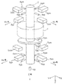
도 1은 본 발명의 하나의 실시예에 적용되는 5축 제어형 자기 베어링의 개략 구성도이다.
도 2은 본 발명의 하나의 실시예에 적용되는 자기 베어링을 구비한 진공 펌프의 구성을 나타내는 단면도이다.
도 3은 본 발명의 하나의 실시예에 적용되는 진공 펌프를 반도체 제조 장치에 부착했을 때의 부착 자세를 나타내는 개념도이다.
도 4는 본 발명의 하나의 실시예에 적용되는 자기 베어링과 제어 기기로 이루어지는 자기 베어링 장치의 구성을 나타내는 개념도이다.
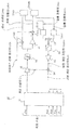
도 5는 본 발명의 하나의 실시예에 적용되는 자기 베어링의 제어 기기의 제어 계통을 나타내는 블럭도이다. 1 is a schematic configuration diagram of a 5-axis controlled magnetic bearing applied to one embodiment of the present invention.
2 is a cross-sectional view showing a configuration of a vacuum pump having a magnetic bearing applied to one embodiment of the present invention.
3 is a conceptual diagram showing an attachment posture when a vacuum pump applied to one embodiment of the present invention is attached to a semiconductor manufacturing apparatus.
4 is a conceptual diagram showing the configuration of a magnetic bearing device comprising a magnetic bearing and a control device applied to one embodiment of the present invention.
5 is a block diagram showing a control system of a control device of a magnetic bearing according to an embodiment of the present invention.
본 발명은, 초기 조정이 간단하며, 제어 기기의 메모리 용량을 늘리지 않고, 간단한 알고리즘으로 최적의 베어링 제어를 행한다는 목적을 달성하기 위해, 전자석의 전자력에 의해 로터축을 비접촉으로 지지하는 자기 베어링과, 자기 베어링을 제어하는 제어 기기를 구비한 자기 베어링 장치로서, 제어 기기는, 자기 베어링의 로터축을 반대 방향으로 서로 끌어당기는 한 쌍의 전자석의 각각에 흐르는 전류 정상치를 취득하는 전류 취득 수단과, 전류 정상치로부터, 자기 베어링의 부착 자세에 기인하여 발생하는 한 쌍의 전자석의 흡인력에 의한 불안정 스프링 상수를 보상하는 보정 게인 지령치를 구하는 보정 계수 연산 수단과, 보정 게인 지령치와 자기 베어링의 부착 자세에 관계없이 일의적으로 정해지는 기본 게인을 가산하여 게인 지령치를 구하는 제1 가산 수단과, 게인 지령치에 의거하여 생성된 전류 지령치에 의해, 한 쌍의 상기 전자석의 각각에 흐르는 전류를 제어하는 전류 제어 수단을 구비하고 있는 것에 의해 실현된다. SUMMARY OF THE INVENTION The present invention is directed to a magnetic bearing device which has a magnetic bearing for supporting the rotor shaft in a noncontact manner by the electromagnetic force of the electromagnet, A magnetic bearing device comprising a control device for controlling a magnetic bearing, the control device comprising: current acquisition means for acquiring a current normal value flowing through each of a pair of electromagnets pulling the rotor shaft of the magnetic bearing in opposite directions to each other; A correction coefficient calculating means for obtaining a correction gain instruction value for compensating for an unstable spring constant due to the attraction force of the pair of electromagnets caused by the mounting posture of the magnetic bearing, And the basic gain determined by itself is added to obtain the gain command value By the current command value created on the basis of the first addition means and the gain command value is realized by being provided with a current control means for controlling the current flowing in each of the pair of the electromagnets.
즉, 본 발명의 실시 형태에 관련된 자기 베어링 장치는, 자기 베어링의 로터축을 래디얼 방향으로 반대 방향으로 서로 끌어당기는 한 쌍의 전자석의 각 전류 정상치(Ip, Im)를 취득한다. 그리고, 자기 베어링의 부착 자세에 따라 각 전류를 최적으로 변화시키기 위해, 취득한 각 전류 정상치(Ip, Im)로부터 전자석에 작용하는 불안정 보상 게인(보정 게인 지령치) Kcomp를 계산한다. 다음에, 전자석의 제어 회로의 기본 게인 Kctrl에 보정 게인 지령치 Kcomp를 가산하여 게인 지령치를 생성한다. 그리고, 이 게인 지령치에 의해 보정된 전류 지령치로 자기 베어링을 제어한다. 이것에 의해, 자기 베어링의 부착 자세가 변화해도, 항상 최적의 상태로 자기 베어링을 제어할 수 있다. That is, the magnetic bearing device according to the embodiment of the present invention acquires the respective current normal values Ip and Im of the pair of electromagnets pulling the rotor shaft of the magnetic bearing in the opposite direction in the radial direction. Then, an unstable compensation gain (correction gain instruction value) Kcomp acting on the electromagnet is calculated from each of the obtained current normal values Ip and Im to optimally change each current according to the mounting posture of the magnetic bearing. Next, a gain command value is generated by adding the correction gain command value Kcomp to the basic gain Kctrl of the control circuit of the electromagnet. Then, the magnetic bearing is controlled by the current command value corrected by the gain instruction value. Thus, even if the mounting posture of the magnetic bearing changes, it is possible to always control the magnetic bearing in an optimal state.
[실시예][Example]
이하, 본 발명에 관련된 자기 베어링 장치의 적합한 실시예에 대해서, 도 1 내지 도 5를 참조하면서 상세하게 설명한다. 도 1은, 본 발명의 하나의 실시예에 적용되는 5축 제어형 자기 베어링의 개략 구성도이다. 이 5축 제어형 자기 베어링은, 래디얼 4축에 제어용 전자석과 변위 센서를 배치하고, 엑시얼 1축에 제어용 전자석과 변위 센서를 배치한 구성을 나타내고 있다. 즉, 이 5축 제어형 자기 베어링은, 회전축 둘레의 자유도를 제외한 5자유도(중심의 병진 운동에 대해서 3개의 자유도, 중심 둘레의 회전 운동에 대해서 2개의 자유도)의 운동을 능동적으로 제어하도록 구성되어 있다. Hereinafter, a preferred embodiment of the magnetic bearing device according to the present invention will be described in detail with reference to Figs. 1 to 5. Fig. 1 is a schematic configuration diagram of a 5-axis controlled magnetic bearing applied to one embodiment of the present invention. The five-axis control type magnetic bearing shows a configuration in which a control electromagnet and a displacement sensor are disposed on four radial axes, and a control electromagnet and a displacement sensor are disposed on one axial axis. That is, the 5-axis controlled type magnetic bearing can actively control the motion of 5 degrees of freedom (three degrees of freedom for the center translational motion and two degrees of freedom for the rotational motion about the center) except for the degree of freedom about the axis of rotation Consists of.
이 5축 제어형 자기 베어링은, DC 모터(1)에 의해 회전 구동되는 로터축(회전축)(2)의 상방측의 반경 방향(래디얼 방향)으로, 4개의 래디얼 전자석(3xp, 3xm, 3yp, 3ym)이, 각각, X축, Y축마다 페어(한 쌍)로 배치되어 있다. 또, 각 래디얼 전자석(3xp, 3xm, 3yp, 3ym)의 위치에 대응하여, 각각 래디얼 센서(4xp, 4xm, 4yp, 4ym)가 배치되어 있다. 동일하게 하여, DC 모터(1)의 하방측에 있어서의 로터축(2)의 반경 방향(래디얼 방향)으로 4개의 래디얼 전자석(5xp, 5xm, 5yp, 5ym)이, 각각, X축, Y축마다 페어로 배치되어 있다. 또, 각 래디얼 전자석(5xp, 5xm, 5yp, 5ym)의 위치에 대응하여, 각각 래디얼 센서(6xp, 6xm, 6yp, 6ym)가 배치되어 있다. 이러한 8개의 래디얼 전자석(3xp, 3xm, 3yp, 3ym, 5xp, 5xm, 5yp, 5ym)에 의해 래디얼 자기 베어링을 구성하고 있다. The 5-axis control type magnetic bearing has four radial electromagnets 3xp, 3xm, 3yp and 3ym (radial direction) in the radial direction (radial direction) above the rotor shaft (rotation axis) 2 driven by the DC motor 1 ) Are arranged in pairs (pair) on the X-axis and Y-axis, respectively. Radial sensors 4xp, 4xm, 4yp and 4ym are arranged corresponding to the positions of the radial electromagnets 3xp, 3xm, 3yp and 3ym, respectively. Similarly, four radial electromagnets 5xp, 5xm, 5yp, and 5ym in the radial direction (radial direction) of the
또한, 로터축(2)의 축 방향(엑시얼 방향)에는, 2개의 엑시얼 전자석(7zm, 7zp)이 상하 페어로 배치되어, 엑시얼 자기 베어링을 구성하고 있다. 또한, 로터축(2)의 하단부에는 엑시얼 센서(8z)가 배치되어 있다. Two axially electromagnets 7zm and 7zp are arranged in the upper and lower pairs in the axial direction (axial direction) of the
이러한 래디얼 전자석(3xp, 3xm, 3yp, 3ym, 5xp, 5xm, 5yp, 5ym)과 래디얼 센서(4xp, 4xm, 4yp, 4ym, 6xp, 6xm, 6yp, 6ym)는, X축, Y축 방향이 각각 페어로 독립적으로 피드백 제어계를 구성하고, 전류(여자 전류)를 제어하여 각 래디얼 전자석의 흡인력을 조절하고 있다. 이것에 의해, 로터축(2)은, 회전축이 중심 위치가 되도록 제어되면서 DC 모터(1)에 의해 회전 구동된다. 또한, 엑시얼 전자석(7zm, 7zp)과 엑시얼 센서(8z)도 피드백 제어계를 구성하고 있다. 또한, 상술한 X축, Y축, Z축 방향을 상세하게 설명하면 다음과 같이 된다. 도 1의 상부 베어링측의 X축은 Xh축, 상부 베어링측의 Y축은 Yh축이 된다. 또, 도 1 하부 베어링측의 X축은 Xb축, 하부 베어링측의 Y축은 Yb축이 된다. 또한, 로터축(2)의 축 방향은 Z축이 된다. These radial electromagnets (3xp, 3xm, 3yp, 3ym, 5xp, 5xm, 5yp, 5ym) and radial sensors (4xp, 4xm, 4yp, 4ym, 6xp, 6xm, 6yp, The feedback control system is configured independently of the pair, and the attraction force of each radial electromagnet is controlled by controlling the current (excitation current). As a result, the
도 2은, 본 발명의 하나의 실시예에 적용되는 자기 베어링을 구비한 진공 펌프의 구성을 나타내는 단면도이다. 이 진공 펌프는 복합 날개를 구비한 터보 분자 펌프를 구성하고 있다. 도 2에 나타내는 바와 같이, 진공 펌프(21)의 중앙 부분에 로터축(2)이 회전 가능하게 배치되고, 그 로터축(2)의 중앙부에는 그 로터축(2)을 회전 구동시키기 위한 DC 모터(1)가 부착되어 있다. 또, DC 모터(1)의 상부에 위치하는 로터축(2)의 래디얼 방향에는 래디얼 전자석(3)이 배치되고, 로터축(2)의 일방의 자기 베어링을 구성하고 있다. 또한, 래디얼 전자석(3)의 근방에는, 로터축(2)의 변위를 검출하기 위한 래디얼 센서(4)가 배치되어 있다. 2 is a cross-sectional view showing a configuration of a vacuum pump having a magnetic bearing applied to one embodiment of the present invention. This vacuum pump constitutes a turbo-molecular pump having a composite vane. 2, a
또, DC 모터(1)의 하부에 위치하는 로터축(2)의 래디얼 방향에는 래디얼 전자석(5)이 배치되고, 로터축(2)의 타방의 자기 베어링을 구성하고 있다. 또한, 래디얼 전자석(5)의 근방에는, 로터축(2)의 변위를 검출하기 위한 래디얼 센서(6)가 배치되어 있다. A
또한, 로터축(2)의 하단부 근방에는 엑시얼 방향으로 엑시얼 전자석(7)이 배치되어, 로터축(2)의 엑시얼 방향의 자기 베어링을 구성하고 있다. 또, 로터축(2)의 하단부에는 로터축(2)의 엑시얼 방향의 변위를 검출하기 위한 엑시얼 센서(8)가 배치되어 있다. 또한, 로터축(2)의 상단부 및 하단부에는, 각각, 보호용 드라이 베어링(11, 12)이 배치되어, 래디얼 자기 베어링(4, 5)의 발진 등에 의해 로터축(2)이 이상(異常)적으로 변위하는 것을 억제하고 있다. An exciting electromagnet 7 is disposed in the vicinity of the lower end of the
또, 진공 펌프(21)의 고정측에는 스테이터 날개(13)가 배치되고, 그 스테이터 날개(13)에 대향하여 로터 날개(14)가 회전 가능하게 배치되어 있다. 이러한 구성에 의해, DC 모터(1)의 회전 구동에 의해 로터축(2)이 회전하면, 로터 날개(14)가 스테이터 날개(13)에 대해 상대적으로 회전하므로, 도시하지 않는 용기로부터의 공기는 흡기구 플랜지(15)로부터 흡인되어 배기구 플랜지(16)로부터 외부로 배출된다. 이러한 진공 펌프(21)는, 예를 들면, 800Hz(1.25msec/1회전)의 회전 속도로 고속 회전하기 때문에, 원하는 용기 내를 극히 높은 진공 상태로 유지할 수 있다. A
도 3은, 본 발명의 하나의 실시예에 적용되는 진공 펌프를 반도체 제조 장치에 부착했을 때의 부착 자세를 나타내는 개념도이다. 도 3에 나타내는 바와 같이, 진공 펌프(21)는, 반도체 제조 장치(22)에 대해 최적의 자세로 부착된다. 예를 들면, 도면의 하방을 중력의 방향으로 하면, 진공 펌프(21a)와 같이 수직 방향으로 부착하거나, 진공 펌프(21b)와 같이 경사 방향으로 부착하거나, 진공 펌프(21c)와 같이 수평 방향으로 부착하거나, 혹은, 진공 펌프(21d)와 같이 도립 방향으로 부착하거나 할 수 있다. 3 is a conceptual diagram showing an attachment posture when a vacuum pump applied to one embodiment of the present invention is attached to a semiconductor manufacturing apparatus. As shown in Fig. 3, the
도 3에 나타내는 바와 같이, 진공 펌프(21a)와 같이 반도체 제조 장치(22)에 대해 수직 방향으로 부착한 경우는, 자기 베어링의 로터축의 자중은 래디얼 방향의 전자석측에는 전혀 가해지지 않지만, 진공 펌프(21c)와 같이 반도체 제조 장치(22)에 대해 수평 방향으로 부착한 경우는, 자기 베어링의 로터축의 전체 자중이 래디얼 방향의 전자석측에 가해진다. 즉, 진공 펌프(21)는 다양한 자세로 반도체 제조 장치(22)에 부착되기 때문에, 그 진공 펌프(21)에 구성되는 자기 베어링의 전자력에는, 중력의 벡터 방향에 기인하여, 로터축의 자중이 변동적으로 가산(감산)된다. 그 때문에, 진공 펌프(21)의 부착 자세에 관계없이 자기 베어링의 강성을 안정적으로 유지하기 위해서는, 비교적 간단한 알고리즘으로 자기 베어링의 전류를 적정하게 제어할 필요가 있다. 그래서, 본 발명의 실시예에서는, 자기 베어링의 부착 자세에 따라 변동하는 전자석의 불안정 스프링 상수의 힘(불안정 요소)을 추출하고, 이 불안정 요소를 불안정 보상 게인으로 하고 있다. 그리고, 자기 베어링의 부착 자세에 관계없이 일의적으로 정해져 있는 기본 게인에 불안정 보상 게인을 가산하여 게인 지령치를 생성하고 있다. 또한, 이 게인 지령치에 의거하여, 각각의 부착 자세에 최적의 전류 지령치를 생성하고, 생성된 전류 지령치에 의해, 한 쌍의 전자석을 적정하게 제어하고 있다. 이하, 이것에 대해서 상세하게 설명한다. As shown in Fig. 3, in the case where the
도 4는, 본 발명의 하나의 실시예에 적용되는 자기 베어링과 제어 기기로 이루어지는 자기 베어링 장치의 구성을 나타내는 개념도이다. 도 4에 나타내는 바와 같이, 자기 베어링 장치(20)는, 자기 베어링(23)과 제어 기기(24)를 구비하여 구성되어 있다. 래디얼 방향의 자기 베어링(23)은, 로터축(2)의 x방향(+x~-x의 방향)에 있어서, 한 쌍의 래디얼 전자석(+x 전자석(3xp)과 -x 전자석(3xm))이 대향하여 배치되어 있다. 또, 각각의 래디얼 전자석(+x 전자석(3xp)과 -x 전자석(3xm))의 근방에는, 각각, x방향의 로터축 변위를 검출하는 래디얼 센서(+x 센서(4xp)와 -x 센서(4xm))가 배치되어 있다. 그리고, 각 래디얼 센서(+x 센서(4xp)와 -x 센서(4xm))로부터의 변위 신호 Sxp, Sxm이 제어 기기(24)로 피드백되고 있다. 또, 제어 기기(24)로부터의 제어 신호(전류) Ixp, Ixm이, x축의 한 쌍의 래디얼 전자석(+x 전자석(3xp)과 -x 전자석(3xm))으로 공급되고 있다. 따라서, 변위 신호 Sxp, Sxm의 피드백에 의해 제어된 전류 Ixp, Ixm에 의해, +x 전자석(3xp)과 -x 전자석(3xm)의 흡인력이 제어되고, 그 결과, 로터축(2)은 기준 위치(중심 위치)로 복귀하도록 움직인다. 4 is a conceptual diagram showing the configuration of a magnetic bearing device comprising a magnetic bearing and a control device applied to one embodiment of the present invention. As shown in Fig. 4, the
또한, 래디얼 방향의 자기 베어링(23)은, 로터축(2)의 y방향에 있어서, 한 쌍의 래디얼 전자석(+y 전자석(3yp)과 -y 전자석(3ym))이 대향하여 배치되어 있다. 또, 각각의 래디얼 전자석(+y 전자석(3yp)과 -y 전자석(3ym))의 근방에는, 각각, y방향의 로터축 변위를 검출하는 래디얼 센서(+y센서(4yp)와 -y센서(4ym))가 배치되어 있다. 또한, 도 4는, x축 방향의 전류를 설명하는 도이기 때문에, y방향의 래디얼 전자석(+y 전자석(3yp)과 -y 전자석(3ym)) 및 y방향의 래디얼 센서(+y센서(4yp)와 -y센서(4ym))에 대해서는 신호 계통이 생략되어 있다. 또, 도 4에서는, x축, y축의 각각의 래디얼 센서(4xp, 4xm, 4yp, 4ym)는, 각각의 래디얼 전자석(3xp, 3xm, 3yp, 3ym)에 고정되어 있는 것처럼 보이지만, 각각의 래디얼 센서(4xp, 4xm, 4yp, 4ym)와 각각의 래디얼 전자석(3xp, 3xm, 3yp, 3ym)은 부착 높이의 위치가 상이하기 때문에, 실제로는 양자는 고정되어 있지 않다. 또한, 로터축(2)이 이상 변위했을 때는, 그 양단 부근에서 보호용 드라이 베어링(11, 12)으로 지지되도록 구성되어 있다(도 2 참조). The radial direction
이러한 구성에 의해, 변위 센서인 래디얼 센서(+x 센서(4xp), -x 센서(4xm))가 로터축(2)의 위치를 검출하여 제어 기기(24)로 변위 신호 Sxp, Sxm을 피드백한다. 그러면, 제어 기기(24)는, 미리 기억되어 있는 기준 위치와의 차에 의거하여 신호 처리를 행하고, 래디얼 전자석(+x 전자석(3xp), -x 전자석(3xm))에 흐르게 하는 전류를 적정하게 결정한다. 그리고, 제어 기기(24) 내의 전류 제어 앰프(도시하지 않음)로부터 래디얼 전자석(+x 전자석(3xp), -x 전자석(3xm))으로 원하는 전류(Ixp, Ixm)를 공급한다. 이것에 의해, 래디얼 전자석(+x 전자석(3xp), -x 전자석(3xm))은 원하는 흡인력에 의해 로터축(2)을 기준 위치(래디얼 방향 x축의 중심 위치)로 복귀시키도록 작동한다. 래디얼 방향의 y축에 대해서도 동일한 동작을 행하여, 로터축(2)을 기준 위치(래디얼 방향 y축의 중심 위치)로 복귀시키도록 작동한다. With this configuration, the radial sensors (+ x sensor 4xp and -x sensor 4xm) as displacement sensors detect the position of the
도 5는, 본 발명의 하나의 실시예에 적용되는 자기 베어링의 제어 기기의 제어 계통을 나타내는 블럭도이다. 이 도면은, 자기 베어링의 로터축에 있어서의 래디얼 방향의 Xh축으로 개재하는 한 쌍의 전자석(래디얼 전자석)의 전류를 제어하는 제어 기기의 제어 계통에 대해서만 표시하고 있다. 5 is a block diagram showing a control system of a control device of a magnetic bearing applied to one embodiment of the present invention. This figure shows only the control system of the control device for controlling the currents of a pair of electromagnets (radial electromagnets) interposed in the radial direction on the Xh axis in the rotor shaft of the magnetic bearing.
먼저, 도 5에 나타내는 자기 베어링의 제어 기기의 구성, 및 각각의 요소의 기능에 대해서 설명한다. 제어 기기(24)는, 래디얼 방향으로 대향하고 있는 한 쌍의 전자석의 전류의 제어를 개별적으로 행하는 전류 제어 앰프(31xp, 31xm)와, 전류 제어 앰프(31xp, 31xm)로부터의 전류 검출치를 각각 제곱화하는 제곱기(32xp, 32xm)와, 각각 제곱화된 전류 검출치를 가산하는 가산기(33)와, 전류 검출치의 제곱·가산치를 평균화하는 로우패스 필터(34)와, 로우패스 필터(34)로부터 출력된 전류 검출치의 제곱·가산치에 보정 계수를 곱하여 보정 게인 지령치의 평균치를 구하는 보정 계수 승산기(35)와, 보정 계수 승산기(35)로부터 출력된 보정 게인 지령치와 기본 게인 설정치를 가산하여 게인 지령치 G를 구하는 가산기(36)와, 로터축의 래디얼 방향의 4축과 스러스트 방향의 1축의 위치 정보를 가지는 힘 지령 중간 신호를 처리하여 출력하는 보상기(37)와, 보상기(37)로부터 출력된 Xh축의 힘 지령 중간 신호를 게인 지령치 G에 의거하여 증폭 처리하는 게인 앰프(38)와, 게인 앰프(38)로부터 출력된 비선형인 힘-전류 지령 중간 신호의 특성을 선형화하는 힘-전류 리니어 라이저(39)와, 선형화된 전류 지령 중간 신호를 분기하여 일방의 신호를 반전시키는 반전기(40)와, 반전되지 않는 쪽의 전류 지령 중간 신호와 바이어스 전류 설정치를 가산하여 전류 지령치를 구하고 전류 제어 앰프(31xp)로 출력하는 가산기(41xp)와, 반전기(40)로 반전된 전류 지령 중간 신호와 바이어스 전류 설정치를 가산하여 전류 지령치를 구하고 전류 제어 앰프(31xm)로 출력하는 가산기(41xm)를 구비하여 구성되어 있다. First, the configuration of the control device of the magnetic bearing shown in Fig. 5 and the function of each element will be described. The control device 24 includes current control amplifiers 31xp and 31xm for individually controlling currents of a pair of electromagnets opposed to each other in the radial direction and current detection values from the current control amplifiers 31xp and 31xm, An adder 33 for adding squared current detection values to each other, squarers 32xp and 32xm for squaring the current detection values, a lowpass filter 34 for averaging squared and added values of the current detection values, A correction coefficient multiplier 35 for multiplying the squared and added values of the output current detection values by a correction coefficient to obtain an average value of the correction gain command values and a correction gain multiplier 35 for adding the correction gain command value and the basic gain setting value output from the correction coefficient multiplier 35, A compensator 37 for processing and outputting a force command intermediate signal having position information of four axes in the radial direction and one axis in the thrust direction of the rotor shaft, A gain amplifier 38 for amplifying the force command intermediate signal of the Xh axis based on the gain command value G and a force-current linearizer 38 for linearizing the characteristics of the nonlinear force-current command intermediate signal output from the gain amplifier 38 (40) for inverting one of the signals by branching the linearized current command intermediate signal, and a current command value by adding the current command intermediate signal and the bias current set value that are not inverted to obtain a current command value, And an adder 41xm for adding the current command intermediate value and the bias current set value inverted by the inverter 40 to obtain a current command value and outputting the current command value to the current control amplifier 31xm Consists of.
다음에, 도 5에 나타내는 각 요소의 기능에 대해서 상세하게 설명한다. 전류 제어 앰프(31xp)는, 로터축의 래디얼 방향으로 대향하고 있는 일방의 +x 전자석(3xp)(도 4 참조)으로 적정한 전류(여자 전류)를 흐르게 하기 위한 기능을 구비하고 있다. 전류 제어 앰프(31xm)는, 로터축의 래디얼 방향으로 대향하고 있는 타방의 -x 전자석(3xm)(도 4 참조)으로 적정한 전류(여자 전류)를 흐르게 하기 위한 기능을 구비하고 있다. Next, the functions of the respective elements shown in Fig. 5 will be described in detail. The current control amplifier 31xp has a function for allowing a proper current (exciting current) to flow through the one + x electromagnet 3xp (see Fig. 4) facing in the radial direction of the rotor shaft. The current control amplifier 31xm has a function of flowing a proper current (exciting current) to the other -x electromagnet 3xm (see Fig. 4) facing in the radial direction of the rotor shaft.
제곱기(32xp) 및 제곱기(32xm)는, 각각, 전류 제어 앰프(31xp) 및 전류 제어 앰프(31xm)로부터, 자기 베어링의 로터축(도시하지 않음)을 각각 x축의 반대 방향으로 서로 끌어당기는 전자석 페어(+x 전자석(3xp)과 -x 전자석(3xm))의 전류 검출치(Ixhp, Ixhm)를 취득하고, 이들 전류 검출치(Ixhp, Ixhm)를 각각 제곱화하는 기능을 구비하고 있다. 가산기(33)는, 제곱기(32xp, 32xm)로 각각 제곱화된 전류 검출치를 가산하여 (Ixhp^2+Ixhm^2)를 구하는 기능을 구비하고 있다. 로우패스 필터(34)는, 노이즈 등을 제거하기 위해, 가산기(33)로부터 출력된 전류의 제곱·가산치 (Ixhp^2+Ixhm^2)를 평균화하는 기능을 구비하고 있다. The squarer 32xp and the squarer 32xm respectively drive the rotor shaft of the magnetic bearing (not shown) from the current control amplifier 31xp and the current control amplifier 31xm, respectively, (Ixhp, Ixhm) of the electromagnet pair (the + x electromagnet 3xp and the -x electromagnet 3xm), and squaring each of these current detection values Ixhp and Ixhm. The
보정 계수 승산기(35)는, 가산기(33)로부터 로우패스 필터(34)를 통하여 출력된 전류의 제곱·가산치 (Ixhp^2+Ixhm^2)에 대해, 로터축의 변위를 보정하기 위한 보정 계수 Kcd를 곱하고, 자기 베어링의 불안정 스프링 상수를 보정하기 위한 보정 게인 지령치 Kcomp=Kcd(Ixhp^2+Ixhm^2)의 평균치를 계산하는 기능을 구비하고 있다. 가산기(36)는, 보정 계수 승산기(35)로부터 출력된 보정 게인 지령치 Kcomp와 자기 베어링의 배치 자세에 관계없이 미리 설정되어 있는 기본 게인 설정치 Kctrl을 가산하여 게인 지령치 G(Kctrl+Kcomp)를 구하는 기능을 구비하고 있다. The
보상기(37)는, 로터축의 래디얼 방향의 4축 Pxh, Pyh, Pxb, Pyb와 스러스트 방향의 1축 Pz로부터의 위치 신호를 처리하여, 로터축의 위치 정보를 가지는 힘 지령 중간 신호를 출력하는 기능을 구비하고 있다. 또한, 위치 신호 Pxh는, 도 1에 나타내는 5축 제어형 자기 베어링에 있어서의 상부의 X축(Xh축) 방향의 한 쌍의 전자석(3xp, 3xm)의 상대적 위치 어긋남을 검출하는 한 쌍의 래디얼 센서(4xp, 4xm)의 신호이다. 또, 위치 신호 Pyh는, 도 1에 나타내는 5축 제어형 자기 베어링에 있어서의 상부의 Y축(Yh축) 방향의 한 쌍의 전자석(3yp, 3ym)의 상대적 위치 어긋남을 검출하는 한 쌍의 래디얼 센서(4yp, 4ym)의 신호이다. 동일하게 하여, 위치 신호 Pxb는, 도 1에 나타내는 5축 제어형 자기 베어링에 있어서의 하부의 X축(Xb축) 방향의 한 쌍의 전자석(5xp, 5xm)의 상대적 위치 어긋남을 검출하는 한 쌍의 래디얼 센서(6xp, 6xm)의 신호이며, 위치 신호 Pyb는, 하부의 Y축(Yb축) 방향의 한 쌍의 전자석(5yp, 5ym)의 상대적 위치 어긋남을 검출하는 한 쌍의 래디얼 센서(6yp, 6ym)의 신호이다. 또, 위치 신호 Pz는, 상하 페어로 Z축 방향으로 배치되어 있는 엑시얼 전자석(7zm, 7zp)의 상대적 위치 어긋남(스러스트 방향의 위치 어긋남)을 검출하는 엑시얼 센서(8z)의 신호이다. 이러한 5축 모든 위치 신호의 처리 계통을 표시하면, 신호 처리 계통의 도면이 복잡하게 되므로, 도 5에서는 대표적으로 위치 신호 Pxh 만의 신호 처리 계통이 표시되어 있다. 게인 앰프(38)는, 보상기(37)에서 생성되어 출력된 Xh축의 힘 지령 중간 신호를 입력하고, 가산기(36)로부터 출력되어 설정된 게인 지령치 G(Kctrl+Kcomp)에 의거하여, Xh축의 힘 지령 중간 신호를 증폭 처리하는 기능을 구비하고 있다. The
힘-전류 리니어 라이저(39)는, 게인 앰프(38)로부터 출력된 비직선성을 가지는 전류 지령 중간 신호(힘-전류 특성의 신호)를, 바이어스 전류 설정치에 의거하여 선형화하는 기능을 구비하고 있다. 또한, 힘-전류 리니어 라이저(39)는, 바이어스 전류 설정치를 검출하여, 한 쌍의 전자석(5xp, 5xm)의 양쪽에 전류가 존재하지 않을 때 만 회로의 전환을 행하여 선형화 기능을 유효화하고 있다. 반전기(40)는, 힘-전류 리니어 라이저(39)로부터 출력된 선형의 전류 지령 중간 신호가 분기된 일방의 신호를 반전시키는 기능을 구비하고 있다. 가산기(41xp)는, 반전되지 않는 쪽의 전류 지령 중간 신호와 바이어스 전류 설정치 OCh를 가산하여 전류 지령치 Cxhp를 구하고, 이 전류 지령치 Cxhp를 전류 제어 앰프(31xp)로 출력하는 기능을 구비하고 있다. 가산기(41xm)는, 반전기(40)로 반전된 전류 지령 중간 신호와 바이어스 전류 설정치 OCh를 가산하여 전류 지령치 Cxhm을 구하고, 이 전류 지령치 Cxhm을 전류 제어 앰프(31xm)로 출력하는 기능을 구비하고 있다. The force-
다음에, 도 5에 나타내는 자기 베어링의 제어 기기의 동작에 대해서 도 4를 참조하면서 설명한다. 여기에서는, 로터축의 래디얼 방향의 Xh축에 대향하는 한 쌍의 전자석(+x 전자석(3xp)과 -x 전자석(3xm): 도 4 참조)의 바이어스 전류를 제어하는 경우를 예로 들어 설명한다. Next, the operation of the control device of the magnetic bearing shown in Fig. 5 will be described with reference to Fig. Here, the case of controlling the bias current of a pair of electromagnets (+ x electromagnets 3xp and -x electromagnets 3xm: see Fig. 4) opposed to the Xh axis in the radial direction of the rotor shaft is described as an example.
먼저, 로터축을 각각 반대 방향으로 서로 끌어당기는 한 쌍의 전자석 페어(+x 전자석(3xp)과 -x 전자석(3xm))의 전류 검출치(Ixhp, Ixhm)를, 각각, 전류 제어 앰프(31xp, 31xm)로부터 취득하고, 제곱기(32xp, 32xm)와 가산기(33)를 이용하여 전류 검출치의 제곱의 합 (Ixhp^2+Ixhm^2)을 계산한다. 그리고, 로우패스 필터(34)를 통과시켜 (Ixhp^2+Ixhm^2)를 평균화한 후, 보정 계수 연산기(35)로 평균화한 (Ixhp^2+Ixhm^2)에 보정 계수 Kcd를 곱하고, 자기 베어링의 불안정성(불안정 스프링 상수)을 보정하는 보정 게인 지령치 Kcomp=Kcd(Ixhp^2+Ixhm^2)의 평균치를 계산한다. 또한, 제곱기(32xp, 32xm)로 입력하는 것은, 전류 검출치(Ixhp, Ixhm)가 아닌, 바이어스 전류 지령치(Cxhp, Cxhm)여도 된다. 또, 로우패스 필터(34)를 이용하지 않아도 기본적인 동작에는 지장은 없지만, 자기 베어링의 로터축의 회전에 의해 발생하는 노이즈 장해 등을 방지하기 위해 로우패스 필터(34)를 이용하는 것이 바람직하다. First, the current detection values Ixhp and Ixhm of a pair of electromagnet pairs (+ x electromagnet 3xp and -x electromagnet 3xm) pulling the rotor axes in opposite directions to each other are inputted to current control amplifiers 31xp, And calculates the sum (Ixhp ^ 2 + Ixhm ^ 2) of the squares of the current detection values by using the squarers 32xp and 32xm and the
다음에, 가산기(36)가, 보정 계수 연산기(35)로 구한 보정 게인 지령치 Kcomp와, 자기 베어링의 배치 자세에 관계없이 일의적으로 정해지는 기본 게인 Kctrl을 가산하여 게인 지령치 G(Kctrl+Kcomp)를 구하고, 이 게인 지령치 G(Kctrl+Kcomp)를 게인 앰프(38)에 설정한다. Next, the
한편, 보상기(37)는, 래디얼 방향 4축의 Pxh, Pyh, Pxb, Pyb로부터의 로터축의 위치 신호를 각각 처리하여, 각 축의 힘 지령 중간 신호를 생성한다. 여기에서는, 보상기(37)가 Xh축의 힘 지령 중간 신호를 생성하는 경우에 대해서 설명한다. 보상기(37)에서 생성된 Xh축의 힘 지령 중간 신호는, 게인 지령치 G(Kctrl+Kcomp)의 설정된 게인 앰프(38)에 입력된다. 이것에 의해, 게인 앰프(38)는, 자기 베어링의 배치 자세에 의거하는 기본 게인 Kctrl에 대해 불안정 스프링 상수가 보정된 게인 지령치 G(Kctrl+Kcomp)에 의거하여, Xh축의 힘 지령 중간 신호를 증폭 처리하여 출력한다. On the other hand, the compensator 37 processes the position signals of the rotor axes from Pxh, Pyh, Pxb, and Pyb in the four radial directions to generate a force command intermediate signal for each axis. Here, the case where the
다음에, 전자석의 흡인력은 전류의 제곱에 비례하기 때문에 힘-전류 특성은 비직선성을 가지므로, 게인 앰프(38)로부터의 출력 신호(힘 지령 중간 신호)는, 힘-전류 리니어 라이저(39)에 입력되어 바이어스 전류 설정치 OCh에 의해 선형화된다. 따라서, 힘-전류 리니어 라이저(39)는, 바이어스 전류 설정치 OCh를 검출하여, 전류가 존재할 때 만 회로의 전환을 행하여 선형화 기능을 유효화하고 있다. 또한, 힘-전류 리니어 라이저(39)는 이용하지 않아도 되지만, 그 경우는 전류 보정의 제어 성능이 열화된다. Since the attraction force of the electromagnet is proportional to the square of the current, the output signal (force command intermediate signal) from the
다음에, 힘-전류 리니어 라이저(39)의 출력의 힘 지령 중간 신호를 분기하여, 일방의 신호는 그대로의 극성으로 하고, 타방의 신호를 반전기(40)로 반전시킨다. 이것은, 로터축의 래디얼 방향에 있어서의 Xh축의 양측에 대향하여 개재하는 한 쌍의 래디얼 전자석(+x 전자석(3xp)과 -x 전자석(3xm))에 대해 반대 극성의 전류를 흐르게 하기 위해서이다. Next, the force command intermediate signal of the output of the force-
즉, 힘-전류 리니어 라이저(39)로부터 출력된 분기 신호의 일방의 힘 지령 중간 신호는, 그대로 가산기(41xp)에서 바이어스 전류 설정치 OCh가 가산되어 전류 지령치 Cxhp로서 생성되고, 분기 신호의 타방의 힘 지령 중간 신호는, 반전기(40)에 의해 반전되고 나서 가산기(41xm)에서 바이어스 전류 설정치 OCh가 가산되어 전류 지령치 Cxhm로서 생성되게 된다. 바꾸어 말하면, 래디얼 방향에 있어서 반대 방향으로 서로 끌어당기는 전자석 페어(+x 전자석(3xp)과 -x 전자석(3xm))의 각각의 전류 지령치(Cxhp, Cxhm)가 생성되고, 이들 전류 지령치(Cxhp, Cxhm)가 각각 전류 제어 앰프(31xp, 31xm)에 입력된다. In other words, one of the intermediate force command signals of the branch signal output from the force-
이것에 의해, 전류 제어 앰프(31xp)로부터, 자기 베어링의 배치 자세에 의거하는 불안정 스프링 상수가 보정된 전류가, 래디얼 방향에 있어서의 Xh축의 일방에 배치된 래디얼 전자석(+x 전자석(3xp))에 흐르고, 전류 제어 앰프(31xm)로부터, 자기 베어링의 배치 자세에 의거하는 불안정 스프링 상수가 보정된 전류가, 래디얼 방향에 있어서의 Xh축의 타방에 배치된 래디얼 전자석(-x 전자석(3xm))에 흐른다. As a result, a current corrected from the current control amplifier 31xp based on the unbalanced spring constant based on the arrangement posture of the magnetic bearing is converted into a radial electromagnet (+ x electromagnet 3xp) arranged on one side of the Xh axis in the radial direction, And the current whose correction of the unstable spring constant based on the arrangement posture of the magnetic bearing is corrected from the current control amplifier 31xm to the radial electromagnet (-x electromagnet 3xm) arranged on the other side of the Xh axis in the radial direction Flows.
즉, 자기 베어링의 로터축이 중력에 대해 수직으로 설치된 경우는 Xh축에는 중력이 걸리지 않기 때문에, 전자석에는 바이어스 전류 설정치 OCh에 따른 작은 전류 밖에 흐르지 않는다. 그 때문에, 게인 앰프(38)에 설정되는 게인 지령치 G(Kctrl+Kcomp)는 작은 값이 되어, 낮은 게인으로 자기 베어링의 전류가 제어된다. That is, when the rotor shaft of the magnetic bearing is installed perpendicular to gravity, gravity is not applied to the Xh axis, so that only a small current according to the bias current setting value OCh flows through the electromagnet. Therefore, the gain command value G (Kctrl + Kcomp) set in the
여기서, 로터축의 자세가 수평으로 변경되면, Xh축에는 중력에 대항하여 로터축을 부상시키기 위해 큰 전류가 전자석에 흐른다. 큰 전류가 흐르면, 자기 베어링의 불안정 스프링 상수 Kd가 증대하여, 그대로는 자기 베어링의 강성이 저하되어 버린다. 그래서, 본 발명에 있어서의 실시예의 구성에서는, 게인 앰프(38)에 설정되는 게인 지령치 G(Kctrl+Kcomp)가 큰 값이 되어, 높은 게인으로 증폭된 전류 지령치에 의해 자기 베어링이 제어되기 때문에, 자기 베어링의 강성이 저하되지 않아, 자기 베어링은 적정한 강성을 확보할 수 있다. Here, when the attitude of the rotor shaft is changed horizontally, a large current flows through the electromagnet in order to float the rotor axis against gravity on the Xh axis. If a large current flows, the unstable spring constant Kd of the magnetic bearing is increased, and the rigidity of the magnetic bearing is lowered as it is. Thus, in the configuration of the embodiment of the present invention, since the gain command value G (Kctrl + Kcomp) set in the
또한, 도 5에 나타내는 제어 기기에 있어서의 전류 보정 기능은, 자기 베어링 장치의 조정 시 등에 있어서, 임의로 해제시킬 수 있다. 그 경우는, 도 4에서 서술한 바와 같이, 래디얼 센서(+x 센서(4xp), -x 센서(4xm))에 의한 변위 신호 Sxp, Sxm의 피드백 만의 제어 기능이 된다. The current correction function in the control device shown in Fig. 5 can be arbitrarily released at the time of adjustment of the magnetic bearing device, and the like. In this case, as described with reference to Fig. 4, only the feedback control of the displacement signals Sxp and Sxm by the radial sensors (+ x sensor 4xp, -x sensor 4xm) becomes a control function.
다음에, 제어 기기에 의한 자기 베어링의 불안정 스프링 상수의 보상 기능에 대해서, 수식을 이용하여 설명한다. 또한, 이하의 수식에 이용하는 각 부호에 대해서는, 각각 다음과 같이 정의한다. Next, the function of compensating the unstable spring constant of the magnetic bearing by the control device will be described using an equation. The respective codes used in the following expressions are defined as follows.
Fo: 현재의, 대향하는 양측의 전자석이 발생시키고 있는 합계의 흡인력(힘)Fo: The total attracting force (force) generated by the current electromagnets on both sides facing each other,
단위〔N〕 Unit [N]
δo: 현재의, 전자석의 에어 갭 단위〔m〕 隆 o: current air gap of the electromagnet Unit [m]
Ipluso: 현재의, +측 전자석(+x 전자석(3xp))의 전류 단위〔A〕 Ipluso: Current of the current, + side electromagnet (+ x electromagnet (3xp)) Unit [A]
Iminuso: 현재의, -측 전자석(-x 전자석(3xm))의 전류 단위〔A〕 Iminuso: current of current-side electromagnet (-x electromagnet (3xm)) Unit [A]
ΔF: 현재와 일순간 후의 사이에 변화하는 흡인력(힘) 단위〔N〕 ΔF: The suction force (force) that varies between the present and the instant after Unit [N]
Δδ: 현재와 일순간 후의 사이에 변화하는 에어 갭 단위〔m〕 [Delta] [delta]: an air gap that varies between the present and the instant after Unit [m]
F: 일순간 후의, 대향하는 양측의 전자석이 발생시키고 있는 합계의 흡인력(힘) 단위〔N〕 F: Total attracting force (force) generated by the electromagnets on both sides facing each other after an instant, Unit [N]
A: 힘과 전류의 제곱의 비례 정수(A=F/I^2) 단위〔N/A^2〕 A: Proportional constant of the square of force and current (A = F / I ^ 2) Unit [N / A ^ 2]
Gctrl: 자기 베어링의 스프링 상수(보정 없는 제어 회로의 기본의 값)Gctrl: Spring constant of the magnetic bearing (default value of control circuit without compensation)
단위〔N/m〕 Unit [N / m]
Kctrl: 보정 게인 가산용 게인 앰프의 기본 게인 단위〔무차원〕 Kctrl: Basic gain of gain amplifier for compensation gain addition Unit [dimensionless]
Krem: 자기 베어링의 스프링 상수 Gctrl로부터 기본 게인 Kctrl을 제외한 나머지의 계수 단위〔N/m〕에 따라서, Gctrl=Kctrl×Krem이 된다. Krem: Gctrl = Kctrl x Krem is obtained from the spring constant Gctrl of the magnetic bearing in accordance with the remaining coefficient units [N / m] except for the basic gain Kctrl.
이상과 같이 각 부호를 정의하면, 일순간 후의, 대향하는 양측의 전자석(+x 전자석(3xp)과 -x 전자석(3xm))이 발생하고 있는 합계의 흡인력(힘)은, 다음의 식 (1)로 표시된다. The sum of the attracting forces (forces) generated by the electromagnets on opposite sides (+ x electromagnets 3xp and -x electromagnets 3xm) after the instant is defined by the following equation (1) .
![]()
![]()
여기서, 보정 파라미터 Kcd와 보정 게인 Kcomp를 도입한다. 또한, Kcd=2A/δo이며, 에어 갭 δo의 변화량은 적기 때문에, 여기에서는, 보정 파라미터 Kcd는 고정 정수로서 취급한다. Here, the correction parameter Kcd and the correction gain Kcomp are introduced. Further, since Kcd = 2A /? O and the variation amount of the air gap? O is small, the correction parameter Kcd is treated as a fixed constant here.
따라서, 보정 게인 Kcomp는, 다음의 식 (2)로 표시된다. Therefore, the correction gain Kcomp is expressed by the following equation (2).
![]()
![]()
여기서, 보정 게인 Kcomp를 회로의 기본 게인 설정치에 가산하면, 일순간 후의, 대향하는 양측의 전자석이 발생시키고 있는 합계의 흡인력 F는, 다음의 식 (3)으로 표시된다. Here, when the correction gain Kcomp is added to the basic gain setting value of the circuit, the total attraction force F generated by the opposite electromagnets on the opposite sides after the instant is expressed by the following equation (3).
![]()
![]()
또한, 일순간 후의 전자석의 힘 “F”를 나타내는 식 (3)에 있어서, 제1항은 현재의 전자석의 힘, 제2항은 자기 베어링이 로터축을 중심으로 되돌리는 스프링의 힘이며, 제3항은 자기 베어링의 불안정 스프링 상수의 힘이며, 제4항은 로터축의 변위를 보정하는 힘이다. In the formula (3) showing the force "F" of the electromagnet after an instant, the first term is the force of the current electromagnet, the second term is the force of the spring that the magnetic bearing is turned around the rotor axis, Is the force of the unstable spring constant of the magnetic bearing, and the fourth is the force of correcting the displacement of the rotor shaft.
상술한 식 (3)은, 식 (4)와 같이 표시된다. The above-described equation (3) is expressed by the equation (4).
![]()
![]()
따라서, 상술한 식 (4)로부터 알 수 있는 바와 같이, 보정 게인 지령치를 기본 게인에 가산함으로써, 대향하는 한 쌍의 전자석의 일순간 후에 있어서의 합계 흡인력(F)은, 한 쌍의 전자석의 현재의 합계 흡인력(F0)에 대해, 로터축을 자기 베어링의 중심으로 되돌리는 스프링력(Gctrl×Δδ) 만이 가해지는 상태가 되어, 자기 베어링의 불안정한 스프링 상수에 의한 흡인력은 없어진다. 즉, 대향하는 한 쌍의 전자석은, 로터축을 자기 베어링의 중심으로 되돌리는 힘 만이 작용하게 된다. Therefore, as can be seen from the above-mentioned equation (4), by adding the correction gain command value to the basic gain, the total attraction force F after a moment of the pair of opposing electromagnets becomes Only the spring force (Gctrl x delta) for returning the rotor shaft to the center of the magnetic bearing is applied to the total attracting force F0, and the suction force due to the unstable spring constant of the magnetic bearing is lost. That is, only a pair of opposing electromagnets act on a force that returns the rotor shaft to the center of the magnetic bearing.
또한, 상술한 각 식으로 나타낸 (Ipluso^2+Iminuso^2)에는 자기 베어링의 회전 주파수에 기인하는 리플이나 노이즈가 포함되므로, 식 (2)로 나타낸 보정 게인 Kcomp=Kcd×(Ipluso^2+Iminuso^2)의 계산은, 이 신호를 약 1Hz 정도의 로우패스 필터를 통과시키고 나서 실행할 필요가 있다. (Ipluso ^ 2 + Iminuso ^ 2) described above includes ripple or noise due to the rotation frequency of the magnetic bearing. Therefore, the correction gain Kcomp = Kcd × (Ipluso ^ 2 + The calculation of Iminuso ^ 2 needs to be performed after passing this signal through a low-pass filter of about 1 Hz.
여기서, 특허 청구의 범위에 있어서의 청구항에서 서술하는 각 수단과 도 5에 나타내는 각 요소의 대응 관계에 대해서 설명한다. 전류 취득 수단은, 2개의 제곱기(32xp, 32xm), 및 가산기(33)에 대응한다. 보정 계수 연산 수단은 보정 계수 연산기(35)에 대응한다. 제1 가산 수단은 가산기(36)에 대응한다. 전류 제어 수단은, 게인 앰프(38), 반전기(40), 가산기(41xp, 41xm), 및 전류 제어 앰프(31xp, 31xm)에 대응한다. 제곱화 수단은 제곱기(32xp, 32xm)에 대응한다. 제2 가산 수단은 가산기(33)에 대응한다. 선형 수단은 힘-전류 리니어 라이저(39)에 대응한다. 또한, 본 제어 기능(24)는, 연산 증폭기 등을 이용한 전자 부품(디스크리트)으로 실현되어도 되고, 마이크로 컴퓨터나 DSP(Digital Signal Processor) 등을 이용하여 소프트웨어로 실현되어도 된다. Here, the correspondence between each of the elements described in the claims in the claims and the respective elements shown in Fig. 5 will be described. The current acquisition means corresponds to the two squarers 32xp and 32xm and the
이상, 본 발명의 구체적인 실시예를 설명했지만, 본 발명은 이 실시예에 한정되는 것은 아니고, 본 발명의 정신을 일탈하지 않는 한 다양한 개변을 할 수 있으며, 그리고, 본 발명이 그 개변된 것에 이르는 것은 당연하다. While the invention has been shown and described with reference to certain preferred embodiments thereof, it will be understood by those skilled in the art that various changes and modifications may be made without departing from the spirit of the invention, It is natural.
<산업 상의 이용 가능성>≪ Industrial Availability >
본 발명의 자기 베어링 장치는, 비접촉 지지, 무윤활, 또한 저진동이며 초고속 회전이 가능하므로, 진공 펌프에 한정되지 않고, 원심 압축기, 터빈 발전기, 터보 팽창기, 연삭 스핀들, 혈류 펌프, 반도체 제조 장치, 계측·분석 기기 등에도 유효하게 이용할 수 있다. The magnetic bearing device of the present invention is not limited to a vacuum pump and can be applied to a centrifugal compressor, a turbine generator, a turboexpander, a grinding spindle, a blood flow pump, a semiconductor manufacturing device, a measurement · It can be used effectively for analytical instruments.
1: DC 모터
2: 로터축
3, 3xp, 3xm, 3yp, 3ym, 5, 5xp, 5xm, 5yp, 5ym: 래디얼 전자석
4, 4xp, 4xm, 4yp, 4ym, 6, 6xp, 6xm, 6yp, 6ym: 래디얼 센서
7, 7zp, 7zm: 엑시얼 전자석
8, 8z: 엑시얼 센서
11, 12: 보호용 드라이 베어링
13: 스테이터 날개
14: 로터 날개
15: 흡기구 플랜지
16: 배기구 플랜지
20: 자기 베어링 장치
21, 21a, 21b, 21c, 21d: 진공 펌프
22: 반도체 제조 장치
23: 자기 베어링
24: 제어 기기
31xp, 31xm: 전류 제어 앰프(전류 제어 수단)
32xp, 32zm: 제곱기(전류 취득 수단, 제곱화 수단)
33: 가산기(전류 취득 수단, 제2 가산 수단) 34: 로우패스 필터
35: 보정 계수 연산기(보정 계수 연산 수단) 36: 가산기(제1 가산 수단)
37: 보상기
38: 게인 앰프(전류 제어 수단)
39: 힘-전류 리니어 라이저(선형화 수단)
40: 반전기
41xp, 41xm: 가산기(전류 제어 수단) 1: DC motor 2: Rotor shaft
3xp, 3xm, 3yp, 3ym, 5, 5xp, 5xm, 5yp, 5ym: Radial electromagnet
4, 4x, 4x, 4y, 4y, 6y, 6x, 6x, 6y, 6y: radial sensor
7, 7zp, 7zm:
11, 12: Protective dry bearing 13: Stator blade
14: rotor blade 15: intake port flange
16: Exhaust port flange 20: Magnetic bearing device
21, 21a, 21b, 21c, 21d: Vacuum pump 22: Semiconductor manufacturing apparatus
23: magnetic bearing 24: control device
31xp, 31xm: Current control amplifier (current control means)
32xp, 32zm: squarer (current acquiring means, squaring means)
33: adder (current acquisition means, second addition means) 34: low-pass filter
35: correction coefficient computing unit (correction coefficient calculating means) 36: adder (first adding means)
37: Compensator 38: Gain amplifier (current control means)
39: force-current linearizer (linearizing means) 40:
41xp, 41xm: adder (current control means)
Claims (10)
상기 제어 기기는,
상기 자기 베어링의 상기 로터축을 반대 방향으로 서로 끌어당기는 한 쌍의 상기 전자석의 각각에 흐르는 전류 정상치를 취득하는 전류 취득 수단과,
상기 전류 정상치로부터, 상기 자기 베어링의 부착 자세에 기인하여 발생하는 한 쌍의 상기 전자석의 흡인력에 의한 불안정 스프링 상수를 보상하는 보정 게인 지령치를 구하는 보정 계수 연산 수단과,
상기 보정 게인 지령치와 상기 자기 베어링의 부착 자세에 관계없이 일의적으로 정해지는 기본 게인을 가산하여 게인 지령치를 구하는 제1 가산 수단과,
상기 게인 지령치에 의거하여 생성된 전류 지령치에 의해, 한 쌍의 상기 전자석의 각각에 흐르는 전류를 제어하는 전류 제어 수단을 구비하고 있는 것을 특징으로 하는 자기 베어링 장치. A magnetic bearing device comprising: a magnetic bearing for supporting a rotor shaft in a noncontact manner by an electromagnetic force of an electromagnet; and a control device for controlling the magnetic bearing,
The control device includes:
Current acquiring means for acquiring a current normal value flowing through each of the pair of electromagnets pulling the rotor shaft of the magnetic bearing in opposite directions to each other,
Correction coefficient calculating means for obtaining a correction gain command value for compensating an unstable spring constant due to the attraction force of a pair of the electromagnets caused by the attachment posture of the magnetic bearing from the current normal value,
First adding means for adding a basic gain uniquely determined regardless of the correction gain command value and an attachment posture of the magnetic bearing to obtain a gain command value;
And a current control means for controlling a current flowing in each of the pair of electromagnets by a current command value generated based on the gain command value.
상기 전류 취득 수단은, 한 쌍의 상기 전자석의 각각에 흐르는 전류의 전류 검출치, 또는, 상기 전류 지령치에 의거하여, 상기 전류 정상치를 취득하는 것을 특징으로 하는 자기 베어링 장치. The method according to claim 1,
Wherein the current acquiring means acquires the current normal value on the basis of the current detection value of the current flowing in each of the pair of electromagnets or the current command value.
상기 전류 제어 수단은, 상기 로터축의 위치 정보를 가지는 힘(力) 지령 중간 신호를 상기 게인 지령치에 의해 제어하고, 상기 게인 지령치에 의해 제어된 상기 힘 지령 중간 신호와 바이어스 전류 설정치를 가산하여 상기 전류 지령치를 생성하는 것을 특징으로 하는 자기 베어링 장치. The method according to claim 1 or 2,
Wherein the current control means controls the force command intermediate signal having the position information of the rotor axis by the gain command value and adds the force command intermediate signal and the bias current setting value controlled by the gain command value, And generates a command value.
상기 전류 지령치는, 한 쌍의 상기 전자석에 대해, 상기 불안정 스프링 상수를 없애고, 상기 로터축을 상기 자기 베어링의 중심으로 되돌리는 힘만을 작용시키는 것을 특징으로 하는 자기 베어링 장치. The method according to any one of claims 1 to 3,
Wherein the current command value causes only a force to eliminate the unstable spring constant and return the rotor axis to the center of the magnetic bearing for a pair of the electromagnets.
상기 전류 취득 수단은,
한 쌍의 상기 전자석의 각각에 흐르는 상기 전류 정상치를 개별적으로 제곱화하는 한 쌍의 제곱화 수단과,
한 쌍의 상기 제곱화 수단이 개별적으로 제곱화한 각각의 전류 정상치를 가산하는 제2 가산 수단을 구비하고 있는 것을 특징으로 하는 자기 베어링 장치. The method according to any one of claims 1 to 4,
Wherein the current acquisition means comprises:
A pair of squaring means for individually squaring the current normal value flowing in each of the pair of electromagnets,
And a second addition means for adding the respective current steady values individually squared by said pair of said squaring means.
한 쌍의 상기 제곱화 수단과 상기 제2 가산 수단에 의해 제곱·가산된 전류 정상치를 평균화 처리하여 상기 보정 계수 연산 수단에 건네주는 로우패스 필터를 더 구비하고 있는 것을 특징으로 하는 자기 베어링 장치. The method of claim 5,
Further comprising a low pass filter for averaging the current normal values squared and added by the pair of squaring means and the second adding means and passing the result to the correction coefficient calculating means.
상기 로우패스 필터는, 공진 주파수가 대략 1Hz인 것을 특징으로 하는 자기 베어링 장치. The method of claim 6,
Wherein the low-pass filter has a resonance frequency of approximately 1 Hz.
상기 전류 제어 수단이 생성한 전류 지령치와 상기 전자석의 흡인력의 관계를 나타내는 비선형 특성을 상기 바이어스 전류 설정치에 의해 선형화하는 선형화 수단을 더 구비하고 있는 것을 특징으로 하는 자기 베어링 장치. The method according to any one of claims 3 to 7,
Further comprising a linearizing means for linearizing the nonlinear characteristic indicating the relationship between the current command value generated by the current control means and the attraction force of the electromagnet by the bias current setting value.
상기 선형화 수단은, 한 쌍의 상기 전자석의 양쪽에 전류가 흐르고 있지 않을 때만 기능하는 것을 특징으로 하는 자기 베어링 장치. The method of claim 8,
Wherein the linearizing means functions only when a current does not flow on both sides of the pair of electromagnets.
Applications Claiming Priority (3)
| Application Number | Priority Date | Filing Date | Title |
|---|---|---|---|
| JPJP-P-2013-246961 | 2013-11-29 | ||
| JP2013246961A JP6321949B2 (en) | 2013-11-29 | 2013-11-29 | Magnetic bearing device and vacuum pump |
| PCT/JP2014/076500 WO2015079802A1 (en) | 2013-11-29 | 2014-10-03 | Magnetic bearing device and vacuum pump |
Publications (2)
| Publication Number | Publication Date |
|---|---|
| KR20160092995A true KR20160092995A (en) | 2016-08-05 |
| KR102213999B1 KR102213999B1 (en) | 2021-02-08 |
Family
ID=53198756
Family Applications (1)
| Application Number | Title | Priority Date | Filing Date |
|---|---|---|---|
| KR1020167012128A Active KR102213999B1 (en) | 2013-11-29 | 2014-10-03 | Magnetic bearing device and vacuum pump |
Country Status (6)
| Country | Link |
|---|---|
| US (1) | US10359046B2 (en) |
| EP (1) | EP3076036B1 (en) |
| JP (1) | JP6321949B2 (en) |
| KR (1) | KR102213999B1 (en) |
| CN (1) | CN105723107B (en) |
| WO (1) | WO2015079802A1 (en) |
Families Citing this family (7)
| Publication number | Priority date | Publication date | Assignee | Title |
|---|---|---|---|---|
| EP3372854B1 (en) * | 2015-12-10 | 2020-06-24 | Daikin Industries, Ltd. | Magnetic bearing device and compressor |
| JP7148230B2 (en) * | 2017-08-31 | 2022-10-05 | エドワーズ株式会社 | Vacuum pump and controller |
| EP3489518B1 (en) * | 2017-11-28 | 2020-02-12 | Pfeiffer Vacuum Gmbh | Vacuum pump and assembly and method for handling and/or assembly of a vacuum pump |
| CN109707733B (en) * | 2018-11-27 | 2020-05-22 | 清华大学 | Vibration isolation and impact resistance control method and system for magnetic bearing |
| FR3129722B1 (en) * | 2021-11-26 | 2023-11-24 | Skf Magnetic Mechatronics | Device for estimating the sensitivity of a sensor, method and associated system |
| JP2024168908A (en) * | 2023-05-25 | 2024-12-05 | エドワーズ株式会社 | Vacuum pump, magnetic bearing device and rotor |
| US20250271002A1 (en) * | 2024-02-28 | 2025-08-28 | Kla Corporation | Three-axis tuned mass damper for turbo molecular pump |
Citations (3)
| Publication number | Priority date | Publication date | Assignee | Title |
|---|---|---|---|---|
| JPH05141423A (en) * | 1991-11-18 | 1993-06-08 | Mitsubishi Heavy Ind Ltd | Magnetic bearing device attached to movable object |
| JPH0942290A (en) | 1995-07-24 | 1997-02-10 | Shimadzu Corp | Magnetic bearing device |
| JP4017383B2 (en) * | 2001-12-04 | 2007-12-05 | Bocエドワーズ株式会社 | Magnetic bearing control device |
Family Cites Families (11)
| Publication number | Priority date | Publication date | Assignee | Title |
|---|---|---|---|---|
| JPS6483916A (en) * | 1987-09-28 | 1989-03-29 | Hitachi Ltd | Control type magnetic bearing device |
| JPH02134410A (en) * | 1988-11-12 | 1990-05-23 | Toshiba Corp | Controller for magnetic bearing |
| JP2533083Y2 (en) * | 1990-11-30 | 1997-04-16 | セイコー精機株式会社 | Magnetic bearing control device |
| US5256637A (en) * | 1991-07-22 | 1993-10-26 | Mechanical Technology Inc. | Superconducting coil bearings for rotor load |
| JP2835942B2 (en) * | 1995-10-27 | 1998-12-14 | セイコー精機株式会社 | Magnetic bearing control device |
| US6700258B2 (en) * | 2001-05-23 | 2004-03-02 | Calnetix | Magnetic thrust bearing with permanent bias flux |
| JP2004132441A (en) * | 2002-10-09 | 2004-04-30 | Ntn Corp | Magnetic bearing device, through-flow fan device for excimer laser using this magnetic bearing device, program for making computer execute feedback control of magnetic bearing and computer-readable recording medium with program for making computer execute feedback control of magnetic bearing recorded thereon |
| JP2006083924A (en) * | 2004-09-15 | 2006-03-30 | Boc Edwards Kk | Magnetic bearing control device |
| EP1942283B1 (en) * | 2005-07-05 | 2016-10-26 | Ebara Corporation | Magnetic bearing device and method of operating the device |
| CN1315254C (en) * | 2005-07-08 | 2007-05-09 | 北京航空航天大学 | High-performance integrated magnetic suspension flywheel magnetic bearing digital controller |
| JP5279890B2 (en) * | 2011-12-29 | 2013-09-04 | 株式会社大阪真空機器製作所 | Radial direction controller and magnetic bearing device to which it is applied |
-
2013
- 2013-11-29 JP JP2013246961A patent/JP6321949B2/en active Active
-
2014
- 2014-10-03 EP EP14865812.3A patent/EP3076036B1/en active Active
- 2014-10-03 US US15/037,071 patent/US10359046B2/en active Active
- 2014-10-03 WO PCT/JP2014/076500 patent/WO2015079802A1/en not_active Ceased
- 2014-10-03 CN CN201480064003.XA patent/CN105723107B/en active Active
- 2014-10-03 KR KR1020167012128A patent/KR102213999B1/en active Active
Patent Citations (3)
| Publication number | Priority date | Publication date | Assignee | Title |
|---|---|---|---|---|
| JPH05141423A (en) * | 1991-11-18 | 1993-06-08 | Mitsubishi Heavy Ind Ltd | Magnetic bearing device attached to movable object |
| JPH0942290A (en) | 1995-07-24 | 1997-02-10 | Shimadzu Corp | Magnetic bearing device |
| JP4017383B2 (en) * | 2001-12-04 | 2007-12-05 | Bocエドワーズ株式会社 | Magnetic bearing control device |
Also Published As
| Publication number | Publication date |
|---|---|
| EP3076036A4 (en) | 2017-07-12 |
| WO2015079802A1 (en) | 2015-06-04 |
| EP3076036B1 (en) | 2020-08-12 |
| US20160290351A1 (en) | 2016-10-06 |
| CN105723107A (en) | 2016-06-29 |
| EP3076036A1 (en) | 2016-10-05 |
| JP2015105680A (en) | 2015-06-08 |
| JP6321949B2 (en) | 2018-05-09 |
| KR102213999B1 (en) | 2021-02-08 |
| US10359046B2 (en) | 2019-07-23 |
| CN105723107B (en) | 2019-06-18 |
Similar Documents
| Publication | Publication Date | Title |
|---|---|---|
| KR102213999B1 (en) | Magnetic bearing device and vacuum pump | |
| JP4287213B2 (en) | Magnetic bearing device having vibration suppressing function, magnetic bearing device having vibration estimating function, and pump device equipped with the magnetic bearing device | |
| KR100622098B1 (en) | Controlled Magnetic Bearings | |
| JP6695541B2 (en) | Magnetic bearing controller and vacuum pump | |
| US10968949B2 (en) | Magnetic bearing control device and vacuum pump | |
| CN108716471A (en) | A kind of rotor of magnetic suspension molecular pump infinitesimal displacement Active Control Method | |
| WO2019239682A1 (en) | Magnetic bearing control device and magnetic bearing control method | |
| KR100644852B1 (en) | Magnetic Bearing Protection Device and Turbo Molecular Pump | |
| JP2012251486A (en) | Magnetic levitation vacuum pump, whirling estimation method, rotor balance inspection method, and method for adjusting magnetic bearing control gain | |
| JP4476694B2 (en) | Magnetic bearing device and fluid machine provided with magnetic bearing device | |
| JP7447546B2 (en) | Magnetic bearing devices and vacuum pumps | |
| JP6269080B2 (en) | Magnetic bearing device and vacuum pump | |
| JP6801481B2 (en) | Magnetic bearing equipment and vacuum pump | |
| KR20240052743A (en) | Magnetic bearing device and vacuum pump | |
| Sahinkaya et al. | Bias current optimization and fuzzy controllers for magnetic bearings in turbo molecular pumps | |
| JP2957222B2 (en) | Active bearing rotor support controller | |
| JP3785524B2 (en) | Control type magnetic bearing device | |
| JP2002081444A (en) | Magnetic bearing device and method for adjusting sensor sensitivity of magnetic bearing device | |
| CN120074284B (en) | High-speed magnetic suspension motor rotor vibration prevention method, system, electronic equipment and medium | |
| JP5115105B2 (en) | Magnetic bearing system | |
| JP2020012405A (en) | Screw compressor and magnetic bearing control method | |
| KR100280752B1 (en) | Magnetic Bearing Controller for Linear Motion Tables | |
| 张钢 | Dynamic characteristics of a working platform supported by an AMG | |
| CN121336056A (en) | Bearingless motor |
Legal Events
| Date | Code | Title | Description |
|---|---|---|---|
| PA0105 | International application |
St.27 status event code: A-0-1-A10-A15-nap-PA0105 |
|
| PG1501 | Laying open of application |
St.27 status event code: A-1-1-Q10-Q12-nap-PG1501 |
|
| A201 | Request for examination | ||
| P11-X000 | Amendment of application requested |
St.27 status event code: A-2-2-P10-P11-nap-X000 |
|
| P13-X000 | Application amended |
St.27 status event code: A-2-2-P10-P13-nap-X000 |
|
| PA0201 | Request for examination |
St.27 status event code: A-1-2-D10-D11-exm-PA0201 |
|
| E902 | Notification of reason for refusal | ||
| PE0902 | Notice of grounds for rejection |
St.27 status event code: A-1-2-D10-D21-exm-PE0902 |
|
| P11-X000 | Amendment of application requested |
St.27 status event code: A-2-2-P10-P11-nap-X000 |
|
| P13-X000 | Application amended |
St.27 status event code: A-2-2-P10-P13-nap-X000 |
|
| E701 | Decision to grant or registration of patent right | ||
| PE0701 | Decision of registration |
St.27 status event code: A-1-2-D10-D22-exm-PE0701 |
|
| GRNT | Written decision to grant | ||
| PR0701 | Registration of establishment |
St.27 status event code: A-2-4-F10-F11-exm-PR0701 |
|
| PR1002 | Payment of registration fee |
St.27 status event code: A-2-2-U10-U12-oth-PR1002 Fee payment year number: 1 |
|
| PG1601 | Publication of registration |
St.27 status event code: A-4-4-Q10-Q13-nap-PG1601 |
|
| PR1001 | Payment of annual fee |
St.27 status event code: A-4-4-U10-U11-oth-PR1001 Fee payment year number: 4 |
|
| PR1001 | Payment of annual fee |
St.27 status event code: A-4-4-U10-U11-oth-PR1001 Fee payment year number: 5 |
|
| PR1001 | Payment of annual fee |
St.27 status event code: A-4-4-U10-U11-oth-PR1001 Fee payment year number: 6 |
|
| U11 | Full renewal or maintenance fee paid |
Free format text: ST27 STATUS EVENT CODE: A-4-4-U10-U11-OTH-PR1001 (AS PROVIDED BY THE NATIONAL OFFICE) Year of fee payment: 6 |