KR20160106339A - laparoscopic instrument comprising pressure sensor and method for sensing diseased area using thereof - Google Patents
laparoscopic instrument comprising pressure sensor and method for sensing diseased area using thereof Download PDFInfo
- Publication number
- KR20160106339A KR20160106339A KR1020150029118A KR20150029118A KR20160106339A KR 20160106339 A KR20160106339 A KR 20160106339A KR 1020150029118 A KR1020150029118 A KR 1020150029118A KR 20150029118 A KR20150029118 A KR 20150029118A KR 20160106339 A KR20160106339 A KR 20160106339A
- Authority
- KR
- South Korea
- Prior art keywords
- pressure sensor
- pressure
- laparoscopic
- surgical instrument
- laparoscopic surgical
- Prior art date
- Legal status (The legal status is an assumption and is not a legal conclusion. Google has not performed a legal analysis and makes no representation as to the accuracy of the status listed.)
- Granted
Links
Images


Classifications
-
- A—HUMAN NECESSITIES
- A61—MEDICAL OR VETERINARY SCIENCE; HYGIENE
- A61B—DIAGNOSIS; SURGERY; IDENTIFICATION
- A61B90/00—Instruments, implements or accessories specially adapted for surgery or diagnosis and not covered by any of the groups A61B1/00 - A61B50/00, e.g. for luxation treatment or for protecting wound edges
- A61B90/06—Measuring instruments not otherwise provided for
-
- A—HUMAN NECESSITIES
- A61—MEDICAL OR VETERINARY SCIENCE; HYGIENE
- A61B—DIAGNOSIS; SURGERY; IDENTIFICATION
- A61B5/00—Measuring for diagnostic purposes; Identification of persons
- A61B5/0048—Detecting, measuring or recording by applying mechanical forces or stimuli
- A61B5/0053—Detecting, measuring or recording by applying mechanical forces or stimuli by applying pressure, e.g. compression, indentation, palpation, grasping, gauging
-
- A—HUMAN NECESSITIES
- A61—MEDICAL OR VETERINARY SCIENCE; HYGIENE
- A61B—DIAGNOSIS; SURGERY; IDENTIFICATION
- A61B90/00—Instruments, implements or accessories specially adapted for surgery or diagnosis and not covered by any of the groups A61B1/00 - A61B50/00, e.g. for luxation treatment or for protecting wound edges
- A61B90/06—Measuring instruments not otherwise provided for
- A61B2090/064—Measuring instruments not otherwise provided for for measuring force, pressure or mechanical tension
Landscapes
- Health & Medical Sciences (AREA)
- Life Sciences & Earth Sciences (AREA)
- Surgery (AREA)
- Heart & Thoracic Surgery (AREA)
- Molecular Biology (AREA)
- Veterinary Medicine (AREA)
- Engineering & Computer Science (AREA)
- Biomedical Technology (AREA)
- Public Health (AREA)
- Medical Informatics (AREA)
- Pathology (AREA)
- Animal Behavior & Ethology (AREA)
- General Health & Medical Sciences (AREA)
- Nuclear Medicine, Radiotherapy & Molecular Imaging (AREA)
- Oral & Maxillofacial Surgery (AREA)
- Physics & Mathematics (AREA)
- Biophysics (AREA)
- Endoscopes (AREA)
Abstract
Description
본 발명은 압력센서를 구비한 복강경 수술기구에 관한 것으로, 더 상세하게는 수술하고자 하는 환부 위치의 시야 확보가 어려울 경우에도 환부의 정확한 위치를 얻을 수 있도록 구성된 복강경 수술기구에 관한 것이다.The present invention relates to a laparoscopic surgical instrument having a pressure sensor. More particularly, the present invention relates to a laparoscopic surgical instrument configured to obtain a precise position of a diseased part even when it is difficult to obtain a visual field of an affected part.
복강경 수술은 전통적으로 복부에 큰 절개창을 열고 시행하는 개복 수술과 달리, 복부에 0.5~1.5cm 크기의 작은 구멍(절개창)을 여러 개 내고, 그 안으로 비디오 카메라와 각종 기구들을 넣고 시행하는 수술 방법으로 '최소 침습 수술'이라고도 불린다. 복강경 수술은 전통적인 개복 수술과 비교하였을 때, 환자의 입장에서는 절개창의 크기가 작기 때문에 상처가 작게 남아 미용적으로 보기 좋고, 창상으로 인한 통증이 훨씬 작다. 또한 빠른 회복 속도를 보이므로 개복수술에 비하여 재원기간이 짧고, 일상생활로 빠르게 복귀할 수 있다는 장점이 있다.Laparoscopic surgery is a surgical procedure in which a small incision (incision) of 0.5 to 1.5 cm in diameter is made in the abdomen and a video camera and various instruments are inserted into the abdomen, unlike the laparotomy, which traditionally opens a large incision in the abdomen Also called 'minimally invasive surgery'. Laparoscopic surgery, when compared with conventional open surgery, is small in size because of the small size of the incision in terms of the patient, so it looks good on the skin and the pain caused by the wound is much smaller. In addition, because of its rapid recovery rate, it has a shorter period of hospitalization than the open surgery and can return to daily life quickly.
반면, 시술자의 입장에서는 작은 절개창의 삽입된 카메라를 통하여 수술이 시술되기 때문에 시야가 제한되고, 사용되는 수술기재의 제한, 수술기재의 가동범위의 제한 등으로 인하여 난이도가 높게 평가되는 수술이기도 하다.On the other hand, from the viewpoint of the practitioner, since the operation is performed through the inserted camera of the small incision, the view is limited, and the difficulty is highly evaluated due to the limitation of the used surgical base and the limitation of the operation range of the surgical base.
일반적으로 대장에 위치하는 용종 또는 암 조직을 제거하기 위한 복강경 수술에 있어서, 복강경수술기구는 인체 외부에서 복강경을 통해 대장 외측으로 투입되나, 수술하고자 하는 용종 등의 환부는 대장 내측에 위치하기에 환부를 찾는 데에 어려움이 있다. 이에 따라 환부의 시야를 확보하기 위해 내시경의 방향조절 장치를 조작하거나 내시경의 축을 회전시키거나 또는 환자의 체위를 변화시키거나 복부를 눌러 환부를 위치시키는 방법들이 사용되었다. Generally, in a laparoscopic surgery for removing a polyp or cancer tissue located in the large intestine, a laparoscopic surgical instrument is introduced from the outside of the human body through the laparoscope to the outside of the large intestine. However, There are difficulties in finding. In order to secure the field of view of the affected part, there have been used methods of manipulating the direction adjusting device of the endoscope, rotating the shaft of the endoscope, or changing the position of the patient or pressing the abdomen to locate the affected part.
그러나 이러한 방법으로도 시야 확보가 어려운 환부에 있어서, 기존에는 크게 두 가지 방법들이 사용되어 왔다. 첫 번째 방법으로는, 시술자가 복강경수술기구로 대장 외측 부분을 두드리면서 그 내측의 용종 등으로 인한 단단한 부분을 시술자의 느낌에 의존하여 찾는 방법이다. 그러나 이러한 방식으로 환부를 찾아 절제하는 경우에는 시술자의 숙련도에 따라 수술의 정확도 및 수술 경과 시간이 좌우된다는 한계가 있다. However, two methods have been widely used in the area where the field of view is difficult to obtain by this method. As a first method, the practitioner taps the outer part of the colon with a laparoscopic surgical instrument and finds a hard part due to the inner polyp, etc., depending on the feeling of the operator. However, when the lesion is resected in this way, there is a limit to the accuracy of the operation and the lapse of time depending on the skill of the operator.
두 번째 방법으로는, 수술 전 용종 등의 환부에 표지물질이 주입되어, 복강경수술카메라를 통하여 모니터 상에 대장이 염색되어 나타나는 부분을 찾는 방법이 사용되었다. 그러나 표지물질 주입을 위한 별도의 내시경절차가 필요하여 수술시간이 길어지고 환자에게 고통을 주며 표지물질로 인한 부작용도 있다는 문제들이 따른다.In the second method, a labeling material was injected into a lesion such as a polyp before surgery and a portion of the colon was stained on a monitor through a laparoscopic surveillance camera. However, a separate endoscopic procedure is required for the injection of the labeling substance, which leads to prolonged operation time, pain to the patient, and side effects due to the labeling substance.
이러한 문제들 없이 용이하게 환부의 위치 및 조직의 상태를 파악하기 위하여서 미국공개특허 제2014-0206953호는 복부 외측에서 자계를 발생시키는 제1유닛과 환자 복부 내측으로 삽입되어 압력 측정을 통한 조직의 성질에 대한 데이터를 송신하는 제2유닛을 포함한다. In order to easily ascertain the position of the lesion and the state of the tissue without these problems, U.S. Patent Publication No. 2014-0206953 discloses a method for diagnosing a lesion by inserting a first unit for generating a magnetic field outside the abdomen, And a second unit for transmitting data to the second unit.
하지만 이러한 장치를 사용하기 위하여서는 복강경수술기구 중 그래스퍼(grasper)로 제2유닛이 파지되어야 하며, 이에 따라 환부 상으로의 다른 기구들의 효과적인 접근이 어려워질 수 있다. 또한, 제1유닛은 환자 복부 외측에 위치되어야하므로 수술 중 시술자가 별도로 신경 써야하는 부분이 추가되어 수술 과정이 복잡해지고 수술 시간이 길어질 수 있다.However, in order to use such a device, the second unit must be grasped with a grasper in the laparoscopic surgical instrument, which may make effective access to other instruments on the affected part difficult. In addition, since the first unit must be located outside the patient's abdomen, a portion of the operator who is to be careful of the operator during operation is added, which complicates the operation and increases the operation time.
따라서, 시야 확보가 어려운 대장 내측의 환부의 조직 제거 수술의 정확도 및 수술 경과 시간은 시술자의 숙련도에 달려있으며, 환부의 정확한 위치를 제거술 외에 번거로운 다른 과정을 거쳐 파악해야하는 문제들이 해결되어야 할 것이다.Therefore, the accuracy of the tissue removal surgery and the lap time of the affected part of the intestine, which are difficult to secure visibility, depend on the proficiency of the operator, and the problem of identifying the exact location of the lesion through other procedures, which is troublesome in addition to removal, should be solved.
이에, 본 발명은 상기한 바와 같은 종래의 문제점을 감안하여 안출된 것으로, 복강경수술기구 말단 및/또는 측단에 압력센서를 구비시킨 것으로 시술자가 양손에 각각 해당 복강경수술기구를 이용하여 대장 외측을 두드리는 경우 복강경수술 모니터 상에 해당 압력들(각각의 압력 및 그 합)이 표시되도록 구성된 복강경수술 기구를 제공하는 것을 목적으로 한다.SUMMARY OF THE INVENTION Accordingly, it is an object of the present invention to provide a laparoscopic surgical instrument having a pressure sensor at a distal end and / or a lateral end of a laparoscopic surgical instrument, (Each pressure and its sum) displayed on the laparoscopic surgery monitor in the case of a laparoscopic surgeon.
상기한 목적을 달성하기 위하여, 본 발명에 따른 압력센서를 구비한 복강경수술기구는, 파지부가 구비된 본체(100); 상기 본체(100)에서 연장된 연장부(110); 및 상기 연장부(110)의 일측에 형성된 복강경 작업수단(120)을 포함하는 복강경 수술기구로서, 상기 복강경 수술기구는 압력센서(121)를 포함하고, 상기 압력센서(121)로부터 획득되는 측정값을 이용하여 압력의 값이 표시수단(400)을 통해 출력되는 복강경 수술기구를 제공한다.In order to achieve the above object, a laparoscopic surgical instrument having a pressure sensor according to the present invention comprises: a
또한, 상기 압력센서(121)는 상기 작업수단(120)의 말단에 위치하는 것이 바람직하다.In addition, the
또한, 상기 압력센서(121)는 상기 연장부(110)의 측면에 위치하는 것이 바람직하다.The
또한, 상기 복강경 수술기구는 한 쌍이며, 상기 압력센서(121)는 상기 한 쌍의 복강경 수술기구에 각각 위치하는 것이 바람직하다.In addition, it is preferable that the laparoscopic surgical instruments are a pair, and the
또한, 상기 표시수단(400)은 상기 한 쌍의 복강경 수술기구의 한 쌍의 압력센서(120)에서 획득되는 측정값을 이용하는 각각의 압력의 값과, 상기 각각의 압력의 값의 합을 모두 표시하는 것이 바람직하다.In addition, the display means 400 displays the sum of the values of the respective pressures using the measured values obtained by the pair of
또한, 상기 복강경 수술기구는 알림부를 더 포함하며, 상기 한 쌍의 압력센서(120)에서 획득되는 측정값을 이용한 상기 각각의 압력의 값 또는 그 합이 미리 결정된 값 이상인 경우 알림부가 작동하는 것이 바람직하다.In addition, the laparoscopic surgical instrument further includes a notification unit, and when the values of the respective pressures using the measurement values obtained by the pair of
또한, 상기 복강경 수술기구는, 상기 측정값이 저장되는 데이터 저장부(200); 및 상기 데이터 저장부(200)에 저장된 상기 측정값을 분석하여 상기 압력의 값을 연산하는 분석수단(300)을 더 포함하며, 상기 표시수단(400)은, 상기 분석수단(300)에서 연산된 상기 압력의 값을 가시적으로 표시하는 것이 바람직하다.The laparoscopic surgical instrument may further include a
또한, 상기 표시수단(400)은 상기 압력센서(120)에서 측정되어 연산되는 압력의 값을 상기 압력센서(120)의 위치와 함께 출력함으로써, 압력분포를 표시하는 것이 바람직하다.In addition, the display means 400 preferably displays the pressure distribution by outputting the value of the pressure measured and calculated by the
또한, 상기 표시수단(400)은 상기 압력센서(120)의 위치에 따른 압력의 값을 다수 연산함으로써 상기 압력분포를 등고선 형태로 표시하는 것이 바람직하다.The display means 400 preferably displays a plurality of pressure values corresponding to the positions of the
또한, 상기 복강경 수술기구는 카메라를 더 포함하며, 상기 표시수단(400)은 상기 카메라에서 촬영된 영상을 상기 압력분포와 함께 표시하는 것이 바람직하다.In addition, the laparoscopic surgical instrument may further include a camera, and the display means 400 may display an image taken by the camera together with the pressure distribution.
상기와 같은 본 발명에 따른 압력센서를 구비한 복강경수술기구에 의하면, 시술자의 숙련도와 무관하게 수술의 정확도를 높이고 수술 시간을 단축할 수 있다. According to the laparoscopic surgical instrument having the pressure sensor according to the present invention, it is possible to improve the accuracy of operation and shorten the operation time regardless of the skill of the operator.
또한, 정량적으로 모니터상에 압력이 표시되기에 표지물질을 사용하지 않고서도 정확한 환부를 찾을 수 있다.Also, since the pressure is displayed quantitatively on the monitor, it is possible to find the correct part without using the labeling substance.
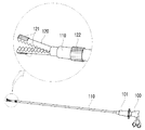
도 1은 본 발명의 일실시예에 따른 압력센서를 구비한 복강경 수술기구를 개략적으로 나타낸 도면이다.
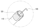
도 2는 본 발명의 다른 일실시예에 따른 압력센서를 구비한 복강경 수술기구를 개략적으로 나타낸 도면이다.
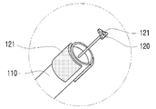
도 3a 내지 도 3d는 각각 본 발명에 따른 압력센서를 구비한 복강경 수술기구의 작업수단(120)의 다양한 실시예들을 나타낸 도면이다.
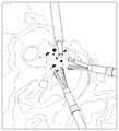
도 4는 본 발명의 일실시예에 따른 압력센서를 구비한 복강경 수술기구가 적용되는 수술 부위를 나타낸 도면이다. 1 is a schematic view of a laparoscopic surgical instrument having a pressure sensor according to an embodiment of the present invention.
2 is a schematic view of a laparoscopic surgical instrument having a pressure sensor according to another embodiment of the present invention.
FIGS. 3A through 3D are views showing various embodiments of a working means 120 of a laparoscopic surgical instrument having a pressure sensor according to the present invention, respectively.
4 is a view illustrating a surgical site to which a laparoscopic surgical instrument having a pressure sensor according to an embodiment of the present invention is applied.
본 발명의 복강경 수술기구를 예로 들어 설명한다. 그러나 동일한 원리가 복강경 수술기구 이외의 기구에도 적용될 수 있다. 따라서, 복강경 수술기구 이외의 동일한 원리가 적용된 다른 기구에도 첨부되는 청구범위에 따라 본 발명의 권리범위가 미침은 자명할 것이다. The laparoscopic surgical instrument of the present invention will be described as an example. However, the same principles can be applied to instruments other than laparoscopic surgical instruments. Accordingly, the scope of the present invention will be evident from the scope of the claims appended to the claims appended to the other apparatuses to which the same principles are applied other than laparoscopic surgical instruments.
본 발명을 이루는 구성요소들은 필요에 따라 일체형으로 사용되거나 각각 분리되어 사용될 수 있다. 또한, 사용 형태에 따라 일부 구성요소를 생략하여 사용가능하다.The constituent elements of the present invention can be used integrally or individually as needed. In addition, some components may be omitted depending on the usage form.
본 발명에 따른 복강경 수술기구의 바람직한 실시예를 도 1 내지 도 4를 참조하여 설명한다. 이 과정에서 도면에 도시된 선들의 두께나 구성요소의 크기 등은 설명의 명료성과 편의상 과장되게 도시되어 있을 수 있다. 또한, 후술되는 용어들은 본 발명에서의 기능을 고려하여 정의된 용어들로서 이는 사용자, 운용자의 의도 또는 관례에 따라 달라질 수 있다. 그러므로 이러한 용어들에 대한 정의는 본 명세서 전반에 걸친 내용을 토대로 기술되어야 할 것이다.
A preferred embodiment of a laparoscopic surgical instrument according to the present invention will be described with reference to Figs. In this process, the thicknesses of the lines and the sizes of the components shown in the drawings may be exaggerated for clarity and convenience of explanation. In addition, the terms described below are defined in consideration of the functions of the present invention, which may vary depending on the intention or custom of the user, the operator. Therefore, the definitions of these terms should be described based on the contents throughout this specification.
이하, 본 발명에 따른 복강경 수술기구의 일실시예를 첨부된 도면을 참조하여 설명한다.Hereinafter, an embodiment of a laparoscopic surgical instrument according to the present invention will be described with reference to the accompanying drawings.
먼저 도 1 및 도 2를 참조하여 복강경 수술기구의 전체 구성을 설명한다. 도 1은 본 발명의 일실시예에 따른 압력센서를 구비한 복강경 수술기구를 개략적으로 나타낸 도면이며, 도 2는 도 1에 도시된 작업수단(120)과 상이한 작업수단(120)을 구비한 파지용 내시경 장치에 압력센서를 구비한 복강경 수술기구를 개략적으로 나타낸 도면이다. First, the entire configuration of a laparoscopic surgical instrument will be described with reference to FIGS. 1 and 2. FIG. FIG. 1 is a schematic view of a laparoscopic surgical instrument having a pressure sensor according to an embodiment of the present invention. FIG. 2 is a perspective view of a laparoscopic surgical instrument having a pressure sensor according to an embodiment of the present invention. A laparoscopic surgical instrument having a pressure sensor in an endoscopic device of the present invention.
본 발명의 일실시예에 따른 압력센서를 구비한 복강경수술기구는, 파지부가 구비된 본체(100), 본체(100)에서 연장된 연장부(110), 연장부(110)의 일측에 형성된 복강경 작업수단(120), 및 작업수단(120)에 형성된 압력센서(121)를 포함한다. A laparoscopic surgical instrument having a pressure sensor according to an embodiment of the present invention includes a
본체(100)에 구비된 파지부는 시술자가 용이하게 잡을 수 있도록 형성된 것이 바람직하며, 파지부의 동작에 의하여 작업수단(120)이 제어될 수 있다. 연장부(110)와 연결된 본체(100)의 일 측에는 조정부(101)가 더 포함되어 형성되는 것이 바람직하며, 조정부(101)의 동작에 따라 작업수단(120)의 동작이 더 세밀하게 조정될 수 있다.The gripping part provided on the
작업수단(120)은 압력센서(121)를 포함하고, 압력센서(121)는 작업수단(120)의 말단에 위치하는 것이 바람직하다. 압력센서(121)가 작업수단(120)의 말단에 위치함으로써 복강경 수술기구를 사용하는 시술자가 작업수단(120)의 말단을 환부 근부에 접촉시킴으로써 접촉된 부위의 압력이 측정될 수 있다. 이때 획득되는 측정값을 이용하여 압력의 값이 표시수단(400)을 통해 출력된다.The working means 120 preferably comprises a
또한, 압력센서(121)는 작업수단(120)의 말단뿐만 아니라 연장부(110)의 측면에 형성될 수도 있다. 압력센서(121)가 연장부(110)의 측면에 형성될 경우, 작업수단(120)의 말단이 뾰죡하여 환부에 접촉시키는 데에 위험성이 따르는 상황에서도 연장부(110)의 측면을 접촉시킴으로써 용이하게 압력의 값을 얻을 수 있다. The
표시수단(400)에 압력센서(121)로부터 얻게 되는 압력의 값이 출력됨으로써 정확한 환부의 위치를 더 용이하게 파악할 수 있다. 표시수단(400)이 형성됨으로써 카메라와 같은 장치를 통하여서도 볼 수 없는 환부의 정확한 위치를 압력센서(121)가 접촉되는 위치에 따라 달라지는 압력의 값을 표시함으로써 파악이 가능하다.The pressure value obtained from the
상술된 바와 같이 본체(100), 연장부(110), 작업수단(120), 압력센서(121) 및 표시수단(400)을 포함하는 복강경 수술기구는 한 쌍으로 사용될 수도 있으며, 압력센서(121)는 이러한 한 쌍의 복강경 수술기구에 각각 위치하는 것이 바람직하다.The laparoscopic surgical instruments including the
도 3a 내지 도 3d는 각각 본 발명에 따른 압력센서를 구비한 복강경 수술기구의 작업수단(120)의 다양한 실시예들을 나타낸 도면들이다. 복강경 수술기구 말단에 형성된 작업수단(120)은 도 3a 내지 도 3d에 도시된 바와 같이 다양한 타입의 내시경 도구로부터 선택적으로 적용될 수 있다. 그러나, 작업수단(120)은 첨부된 도면들 외에 다른 타입의 내시경 기구들도 적용될 수 있음은 물론이다.FIGS. 3A through 3D are views showing various embodiments of a working means 120 of a laparoscopic surgical instrument having a pressure sensor according to the present invention, respectively. The working means 120 formed at the end of the laparoscopic surgical instrument may be selectively applied from various types of endoscopic instruments as shown in Figures 3A-3D. However, it goes without saying that the working means 120 may be applied to other types of endoscopic instruments other than those shown in the accompanying drawings.
복강경 수술기구가 한 쌍으로 사용되는 경우에, 표시수단(400)은 한 쌍의 복강경 수술기구의 한 쌍의 압력센서(120)에서 획득되는 측정값을 이용하는 각각의 압력의 값과, 이의 합을 모두 표시하는 것이 바람직하다. In the case where the laparoscopic surgical instruments are used in pairs, the display means 400 displays the values of the respective pressures using the measurements obtained in the pair of
또한, 복강경 수술기구는 알림부를 더 포함할 수도 있다. 한 쌍의 압력센서(120)에서 획득되는 측정값을 이용한 각각의 압력의 값 또는 그 합이 미리 결정된 값 이상인 경우 알림부가 작동하는 것이 바람직하다. 미리 결정된 값 이상인 경우에 알림부가 작동함으로써 환부의 위치를 더 용이하게 파악할 수 있다.Further, the laparoscopic surgical instrument may further include a notification unit. It is preferable that the notification unit operates when the values of the respective pressures using the measurement values obtained by the pair of
복강경 수술기구는 표시수단(400)뿐만 아니라 측정값이 저장되는 데이터 저장부(200), 및 데이터 저장부(200)에 저장된 측정값을 분석하여 압력의 값을 연산하는 분석수단(300)을 더 포함할 수 있다. 표시수단(400)을 통하여 분석수단(300)에서 연산된 압력의 값을 표시되는 형식은 어느 한 가지로 한정되지 않으나, 가시적으로 환부가 파악될 수 있도록 표시되는 것이 바람직하다. The laparoscopic surgical instrument includes a
표시수단(400)은 상기 압력센서(120)에서 측정되어 연산되는 압력의 값을 압력센서(120)의 위치와 함께 출력함으로써, 압력분포를 표시하는 것이 바람직하다. 예를 들면, 각각의 압력의 값 또는 합산된 압력의 값들이 압력센서(120)의 위치에 따라 다수 연산되어 압력분포가 등고선 형태로 그려짐으로써 환부의 위치가 가시적으로 확인가능할 수 있다. The display means 400 preferably displays the pressure distribution by outputting the value of the pressure measured and calculated by the
더 나아가, 복강경 수술기구는 카메라를 더 포함하여 카메라를 통하여서 촬영된 영상을 표시수단(400)에서 압력분포와 함께 표시될 수 있도록 구성되는 것이 바람직하다. 카메라를 통한 영상자료와 압력분포가 동시에 표시수단(400)에 표시됨으로써 시술자가 더 용이하게 환부의 위치를 파악할 수 있다. Furthermore, it is preferable that the laparoscopic surgical instrument further includes a camera so that an image photographed through the camera can be displayed together with the pressure distribution in the display means 400. [ The image data and the pressure distribution through the camera are simultaneously displayed on the display means 400 so that the operator can more easily grasp the position of the affected part.
상기에서는 본 발명의 바람직한 실시 예를 참조하여 설명하였지만, 당업계에서 통상의 지식을 가진 자라면 이하의 특허청구범위에 기재된 본 발명의 사상 및 영역을 벗어나지 않는 범위 내에서 본 발명을 다양하게 수정 및 변경시킬 수 있음을 이해할 수 있을 것이다.
It will be apparent to those skilled in the art that various modifications and variations can be made in the present invention without departing from the spirit or scope of the invention as defined in the appended claims. It will be understood that the present invention can be changed.
100: 본체
101: 조정부
110: 연장부
120: 작업수단
121: 압력센서
200: 데이터 저장부
300: 분석수단
400: 표시수단100:
101:
110: extension part
120: working means
121: Pressure sensor
200: Data storage unit
300: means of analysis
400: display means
Claims (10)
상기 본체(100)에서 연장된 연장부(110); 및
상기 연장부(110)의 일측에 형성된 복강경 작업수단(120)을 포함하는 복강경 수술기구로서,
상기 복강경 수술기구는 압력센서(121)를 포함하고,
상기 압력센서(121)로부터 획득되는 측정값을 이용하여 압력의 값이 표시수단(400)을 통해 출력되는,
복강경 수술기구.
A main body 100 having a grip portion;
An extension 110 extending from the body 100; And
A laparoscopic surgical instrument comprising a laparoscopic work means (120) formed on one side of the extension (110)
The laparoscopic surgical instrument includes a pressure sensor 121,
And the pressure value is output through the display means 400 using the measurement value obtained from the pressure sensor 121. [
Laparoscopic Surgery Apparatus.
상기 압력센서(121)는 상기 작업수단(120)의 말단에 위치하는,
복강경 수술기구.
The method according to claim 1,
The pressure sensor 121 is located at the end of the working means 120,
Laparoscopic Surgery Apparatus.
상기 압력센서(121)는 상기 연장부(110)의 측면에 위치하는,
복강경 수술기구.
The method according to claim 1,
The pressure sensor 121 is disposed on a side surface of the extension 110,
Laparoscopic Surgery Apparatus.
상기 복강경 수술기구는 한 쌍이며,
상기 압력센서(121)는 상기 한 쌍의 복강경 수술기구에 각각 위치하는,
복강경 수술기구.
4. The method according to any one of claims 1 to 3,
The laparoscopic surgical instrument is a pair,
The pressure sensor (121) comprises a pair of laparoscopic surgical instruments,
Laparoscopic Surgery Apparatus.
상기 표시수단(400)은 상기 한 쌍의 복강경 수술기구의 한 쌍의 압력센서(120)에서 획득되는 측정값을 이용하는 각각의 압력의 값과, 상기 각각의 압력의 값의 합을 모두 표시하는,
복강경 수술기구.
5. The method of claim 4,
The display means 400 displays the sum of the values of the respective pressures using the measured values obtained from the pair of pressure sensors 120 of the pair of laparoscopic surgical instruments,
Laparoscopic Surgery Apparatus.
상기 복강경 수술기구는 알림부를 더 포함하며,
상기 한 쌍의 압력센서(120)에서 획득되는 측정값을 이용한 상기 각각의 압력의 값 또는 그 합이 미리 결정된 값 이상인 경우 알림부가 작동하는,
복강경 수술기구.
5. The method of claim 4,
The laparoscopic surgical instrument further includes a notification unit,
Wherein when the value of each pressure using the measurement value obtained by the pair of pressure sensors (120) or the sum of the pressures is equal to or greater than a predetermined value,
Laparoscopic Surgery Apparatus.
상기 복강경 수술기구는,
상기 측정값이 저장되는 데이터 저장부(200); 및
상기 데이터 저장부(200)에 저장된 상기 측정값을 분석하여 상기 압력의 값을 연산하는 분석수단(300)을 더 포함하며,
상기 표시수단(400)은, 상기 분석수단(300)에서 연산된 상기 압력의 값을 가시적으로 표시하는,
복강경 수술기구.
5. The method of claim 4,
Wherein the laparoscopic surgical instrument comprises:
A data storage unit 200 for storing the measured values; And
And analyzing means (300) for analyzing the measurement value stored in the data storage unit (200) and calculating the pressure value,
The display means (400) displays the pressure value calculated by the analyzing means (300) visually,
Laparoscopic Surgery Apparatus.
상기 표시수단(400)은 상기 압력센서(120)에서 측정되어 연산되는 압력의 값을 상기 압력센서(120)의 위치와 함께 출력함으로써, 압력분포를 표시하는,
복강경 수술기구.
8. The method of claim 7,
The display means 400 outputs a pressure value calculated by the pressure sensor 120 together with the position of the pressure sensor 120,
Laparoscopic Surgery Apparatus.
상기 표시수단(400)은 상기 압력센서(120)의 위치에 따른 압력의 값을 다수 연산함으로써 상기 압력분포를 등고선 형태로 표시하는,
복강경 수술기구.
9. The method of claim 8,
The display means (400) displays the pressure distribution in contour form by calculating a number of pressure values corresponding to the position of the pressure sensor (120)
Laparoscopic Surgery Apparatus.
상기 복강경 수술기구는 카메라를 더 포함하며,
상기 표시수단(400)은 상기 카메라에서 촬영된 영상을 상기 압력분포와 함께 표시하는,
복강경 수술기구.10. The method of claim 9,
Wherein the laparoscopic surgical instrument further comprises a camera,
The display means (400) displays an image photographed by the camera together with the pressure distribution,
Laparoscopic Surgery Apparatus.
Priority Applications (1)
| Application Number | Priority Date | Filing Date | Title |
|---|---|---|---|
| KR1020150029118A KR101721749B1 (en) | 2015-03-02 | 2015-03-02 | laparoscopic instrument comprising pressure sensor and method for sensing diseased area using thereof |
Applications Claiming Priority (1)
| Application Number | Priority Date | Filing Date | Title |
|---|---|---|---|
| KR1020150029118A KR101721749B1 (en) | 2015-03-02 | 2015-03-02 | laparoscopic instrument comprising pressure sensor and method for sensing diseased area using thereof |
Publications (2)
| Publication Number | Publication Date |
|---|---|
| KR20160106339A true KR20160106339A (en) | 2016-09-12 |
| KR101721749B1 KR101721749B1 (en) | 2017-03-30 |
Family
ID=56950194
Family Applications (1)
| Application Number | Title | Priority Date | Filing Date |
|---|---|---|---|
| KR1020150029118A Expired - Fee Related KR101721749B1 (en) | 2015-03-02 | 2015-03-02 | laparoscopic instrument comprising pressure sensor and method for sensing diseased area using thereof |
Country Status (1)
| Country | Link |
|---|---|
| KR (1) | KR101721749B1 (en) |
Cited By (1)
| Publication number | Priority date | Publication date | Assignee | Title |
|---|---|---|---|---|
| CN117064496A (en) * | 2023-09-11 | 2023-11-17 | 南京道壹生物医学科技有限公司 | Laparoscopic forceps with monitoring sensors and high-precision pressure monitoring method |
Families Citing this family (1)
| Publication number | Priority date | Publication date | Assignee | Title |
|---|---|---|---|---|
| KR101993206B1 (en) * | 2018-12-05 | 2019-09-30 | 의료법인 명지의료재단 | Medical drill device for recognizing bend of drill bit |
Citations (5)
| Publication number | Priority date | Publication date | Assignee | Title |
|---|---|---|---|---|
| JPH10216124A (en) * | 1997-02-06 | 1998-08-18 | Olympus Optical Co Ltd | Touch sensor probe |
| JP2000287995A (en) * | 1999-04-06 | 2000-10-17 | Olympus Optical Co Ltd | Microscope apparatus for surgery |
| KR20110036453A (en) * | 2009-10-01 | 2011-04-07 | 주식회사 이턴 | Surgical image processing apparatus and method |
| JP2014094273A (en) * | 2012-10-09 | 2014-05-22 | Kagawa Univ | Endoscope hood, endoscope, pressure sensor for endoscope and tissue size measurement method |
| US20140206953A1 (en) | 2012-09-14 | 2014-07-24 | Vanderbilt University | System and method for detecting tissue surface properties |
-
2015
- 2015-03-02 KR KR1020150029118A patent/KR101721749B1/en not_active Expired - Fee Related
Patent Citations (5)
| Publication number | Priority date | Publication date | Assignee | Title |
|---|---|---|---|---|
| JPH10216124A (en) * | 1997-02-06 | 1998-08-18 | Olympus Optical Co Ltd | Touch sensor probe |
| JP2000287995A (en) * | 1999-04-06 | 2000-10-17 | Olympus Optical Co Ltd | Microscope apparatus for surgery |
| KR20110036453A (en) * | 2009-10-01 | 2011-04-07 | 주식회사 이턴 | Surgical image processing apparatus and method |
| US20140206953A1 (en) | 2012-09-14 | 2014-07-24 | Vanderbilt University | System and method for detecting tissue surface properties |
| JP2014094273A (en) * | 2012-10-09 | 2014-05-22 | Kagawa Univ | Endoscope hood, endoscope, pressure sensor for endoscope and tissue size measurement method |
Cited By (1)
| Publication number | Priority date | Publication date | Assignee | Title |
|---|---|---|---|---|
| CN117064496A (en) * | 2023-09-11 | 2023-11-17 | 南京道壹生物医学科技有限公司 | Laparoscopic forceps with monitoring sensors and high-precision pressure monitoring method |
Also Published As
| Publication number | Publication date |
|---|---|
| KR101721749B1 (en) | 2017-03-30 |
Similar Documents
| Publication | Publication Date | Title |
|---|---|---|
| US12138083B2 (en) | Flattened organ display | |
| JP4512160B2 (en) | Percutaneous surgery measuring instrument | |
| EP1545328B1 (en) | Measurement structure for surgical instruments | |
| US9123155B2 (en) | Apparatus and method for using augmented reality vision system in surgical procedures | |
| CN102525644B (en) | There is the Electrosurgical sealing tool of sense of touch feedback | |
| Miller et al. | Tactile imaging system for localizing lung nodules during video assisted thoracoscopic surgery | |
| US20150216541A1 (en) | Pointing device and drilling tool | |
| US20100249826A1 (en) | Finger mounting for surgical instruments particularly useful in open and endoscopic surgery | |
| KR101670162B1 (en) | Endoscopic tool having sensing and measuring parts and a system comprising the same | |
| EP2978375B1 (en) | Tunnel gage | |
| JP7281837B2 (en) | Surgical sounding instrument | |
| JP2019103792A (en) | Surgical instruments including devices for sensing tissue properties, and methods thereof | |
| KR101721749B1 (en) | laparoscopic instrument comprising pressure sensor and method for sensing diseased area using thereof | |
| JP2023508213A (en) | Navigation trocar with internal camera | |
| US20150182208A1 (en) | Tactile indicator for endoscopic instruments | |
| JP7217065B1 (en) | Force sense display device, force sense display method and program | |
| JP7284868B2 (en) | surgical system | |
| JP2019088784A (en) | Calibration of rigid ent tool | |
| JP2023508209A (en) | Trocar with modular obturator head | |
| EP4195996B1 (en) | Portable disposable microperitoneoscope for direct visualisation of peritoneal cavity of a patient at the point-of-care | |
| EP4595900A1 (en) | Puncture support apparatus, operation method thereof, and non-transitory computer readable medium | |
| US20160157842A1 (en) | Surgical instrument and method of use thereof | |
| US20240023889A1 (en) | System and Method Used to Detect or Differentiate Tissue or an Artifact | |
| WO2023220673A1 (en) | A visual interface for a system used to determine tissue characteristics | |
| KR20150102203A (en) | Apparatus of lesion marker using for endoscope |
Legal Events
| Date | Code | Title | Description |
|---|---|---|---|
| A201 | Request for examination | ||
| PA0109 | Patent application |
St.27 status event code: A-0-1-A10-A12-nap-PA0109 |
|
| PA0201 | Request for examination |
St.27 status event code: A-1-2-D10-D11-exm-PA0201 |
|
| D13-X000 | Search requested |
St.27 status event code: A-1-2-D10-D13-srh-X000 |
|
| D14-X000 | Search report completed |
St.27 status event code: A-1-2-D10-D14-srh-X000 |
|
| E902 | Notification of reason for refusal | ||
| PE0902 | Notice of grounds for rejection |
St.27 status event code: A-1-2-D10-D21-exm-PE0902 |
|
| PN2301 | Change of applicant |
St.27 status event code: A-3-3-R10-R13-asn-PN2301 St.27 status event code: A-3-3-R10-R11-asn-PN2301 |
|
| T11-X000 | Administrative time limit extension requested |
St.27 status event code: U-3-3-T10-T11-oth-X000 |
|
| R17-X000 | Change to representative recorded |
St.27 status event code: A-3-3-R10-R17-oth-X000 |
|
| E13-X000 | Pre-grant limitation requested |
St.27 status event code: A-2-3-E10-E13-lim-X000 |
|
| P11-X000 | Amendment of application requested |
St.27 status event code: A-2-2-P10-P11-nap-X000 |
|
| P13-X000 | Application amended |
St.27 status event code: A-2-2-P10-P13-nap-X000 |
|
| P11-X000 | Amendment of application requested |
St.27 status event code: A-2-2-P10-P11-nap-X000 |
|
| P13-X000 | Application amended |
St.27 status event code: A-2-2-P10-P13-nap-X000 |
|
| P11-X000 | Amendment of application requested |
St.27 status event code: A-2-2-P10-P11-nap-X000 |
|
| P13-X000 | Application amended |
St.27 status event code: A-2-2-P10-P13-nap-X000 |
|
| PG1501 | Laying open of application |
St.27 status event code: A-1-1-Q10-Q12-nap-PG1501 |
|
| E90F | Notification of reason for final refusal | ||
| PE0902 | Notice of grounds for rejection |
St.27 status event code: A-1-2-D10-D21-exm-PE0902 |
|
| P11-X000 | Amendment of application requested |
St.27 status event code: A-2-2-P10-P11-nap-X000 |
|
| P13-X000 | Application amended |
St.27 status event code: A-2-2-P10-P13-nap-X000 |
|
| E701 | Decision to grant or registration of patent right | ||
| PE0701 | Decision of registration |
St.27 status event code: A-1-2-D10-D22-exm-PE0701 |
|
| GRNT | Written decision to grant | ||
| PR0701 | Registration of establishment |
St.27 status event code: A-2-4-F10-F11-exm-PR0701 |
|
| PR1002 | Payment of registration fee |
St.27 status event code: A-2-2-U10-U11-oth-PR1002 Fee payment year number: 1 |
|
| PG1601 | Publication of registration |
St.27 status event code: A-4-4-Q10-Q13-nap-PG1601 |
|
| P22-X000 | Classification modified |
St.27 status event code: A-4-4-P10-P22-nap-X000 |
|
| PR1001 | Payment of annual fee |
St.27 status event code: A-4-4-U10-U11-oth-PR1001 Fee payment year number: 4 |
|
| PR1001 | Payment of annual fee |
St.27 status event code: A-4-4-U10-U11-oth-PR1001 Fee payment year number: 5 |
|
| PN2301 | Change of applicant |
St.27 status event code: A-5-5-R10-R13-asn-PN2301 St.27 status event code: A-5-5-R10-R11-asn-PN2301 |
|
| PC1903 | Unpaid annual fee |
St.27 status event code: A-4-4-U10-U13-oth-PC1903 Not in force date: 20220325 Payment event data comment text: Termination Category : DEFAULT_OF_REGISTRATION_FEE |
|
| R18-X000 | Changes to party contact information recorded |
St.27 status event code: A-5-5-R10-R18-oth-X000 |
|
| PC1903 | Unpaid annual fee |
St.27 status event code: N-4-6-H10-H13-oth-PC1903 Ip right cessation event data comment text: Termination Category : DEFAULT_OF_REGISTRATION_FEE Not in force date: 20220325 |
|
| R18-X000 | Changes to party contact information recorded |
St.27 status event code: A-5-5-R10-R18-oth-X000 |
|
| R18-X000 | Changes to party contact information recorded |
St.27 status event code: A-5-5-R10-R18-oth-X000 |
|
| R18-X000 | Changes to party contact information recorded |
St.27 status event code: A-5-5-R10-R18-oth-X000 |