KR20170010334A - Press systems and methods - Google Patents
Press systems and methods Download PDFInfo
- Publication number
- KR20170010334A KR20170010334A KR1020170006344A KR20170006344A KR20170010334A KR 20170010334 A KR20170010334 A KR 20170010334A KR 1020170006344 A KR1020170006344 A KR 1020170006344A KR 20170006344 A KR20170006344 A KR 20170006344A KR 20170010334 A KR20170010334 A KR 20170010334A
- Authority
- KR
- South Korea
- Prior art keywords
- tool
- blank
- die
- press
- cooling
- Prior art date
- Legal status (The legal status is an assumption and is not a legal conclusion. Google has not performed a legal analysis and makes no representation as to the accuracy of the status listed.)
- Ceased
Links
- 238000000034 method Methods 0.000 title claims abstract description 60
- 238000001816 cooling Methods 0.000 claims abstract description 110
- 238000003825 pressing Methods 0.000 claims abstract description 36
- 230000007246 mechanism Effects 0.000 claims abstract description 30
- 230000013011 mating Effects 0.000 claims abstract description 19
- 238000004519 manufacturing process Methods 0.000 claims abstract description 7
- 238000009966 trimming Methods 0.000 claims description 28
- 238000005520 cutting process Methods 0.000 claims description 23
- 229910000831 Steel Inorganic materials 0.000 claims description 15
- 239000010959 steel Substances 0.000 claims description 15
- 230000009471 action Effects 0.000 claims description 14
- 238000000576 coating method Methods 0.000 claims description 12
- 238000010438 heat treatment Methods 0.000 claims description 12
- 238000012546 transfer Methods 0.000 claims description 12
- 239000011701 zinc Substances 0.000 claims description 12
- HCHKCACWOHOZIP-UHFFFAOYSA-N Zinc Chemical compound [Zn] HCHKCACWOHOZIP-UHFFFAOYSA-N 0.000 claims description 11
- 229910052725 zinc Inorganic materials 0.000 claims description 11
- 239000011248 coating agent Substances 0.000 claims description 9
- 239000007788 liquid Substances 0.000 claims description 8
- 229910052748 manganese Inorganic materials 0.000 claims description 8
- 229910052799 carbon Inorganic materials 0.000 claims description 6
- 239000000498 cooling water Substances 0.000 claims description 6
- 238000004080 punching Methods 0.000 claims description 4
- 229910000797 Ultra-high-strength steel Inorganic materials 0.000 description 12
- 230000008569 process Effects 0.000 description 8
- 239000003570 air Substances 0.000 description 7
- 230000001939 inductive effect Effects 0.000 description 6
- 239000000463 material Substances 0.000 description 6
- 239000000203 mixture Substances 0.000 description 6
- XLYOFNOQVPJJNP-UHFFFAOYSA-N water Substances O XLYOFNOQVPJJNP-UHFFFAOYSA-N 0.000 description 6
- 230000001965 increasing effect Effects 0.000 description 4
- 230000009466 transformation Effects 0.000 description 4
- 230000003750 conditioning effect Effects 0.000 description 3
- 230000001276 controlling effect Effects 0.000 description 3
- 239000012530 fluid Substances 0.000 description 3
- 229910052751 metal Inorganic materials 0.000 description 3
- 239000002184 metal Substances 0.000 description 3
- 238000000465 moulding Methods 0.000 description 3
- 238000010791 quenching Methods 0.000 description 3
- 230000000171 quenching effect Effects 0.000 description 3
- 229910052782 aluminium Inorganic materials 0.000 description 2
- 229910052796 boron Inorganic materials 0.000 description 2
- 238000010276 construction Methods 0.000 description 2
- -1 e.g. Substances 0.000 description 2
- 229910000734 martensite Inorganic materials 0.000 description 2
- 229910052757 nitrogen Inorganic materials 0.000 description 2
- 229910052698 phosphorus Inorganic materials 0.000 description 2
- 238000012545 processing Methods 0.000 description 2
- 229910052717 sulfur Inorganic materials 0.000 description 2
- 229910052719 titanium Inorganic materials 0.000 description 2
- 238000011144 upstream manufacturing Methods 0.000 description 2
- 238000009834 vaporization Methods 0.000 description 2
- 230000008016 vaporization Effects 0.000 description 2
- 229910018125 Al-Si Inorganic materials 0.000 description 1
- 229910018520 Al—Si Inorganic materials 0.000 description 1
- 229910000712 Boron steel Inorganic materials 0.000 description 1
- 229910001209 Low-carbon steel Inorganic materials 0.000 description 1
- 238000010521 absorption reaction Methods 0.000 description 1
- 239000012080 ambient air Substances 0.000 description 1
- 229910001566 austenite Inorganic materials 0.000 description 1
- 239000012809 cooling fluid Substances 0.000 description 1
- 230000007797 corrosion Effects 0.000 description 1
- 238000005260 corrosion Methods 0.000 description 1
- 238000011161 development Methods 0.000 description 1
- 238000007723 die pressing method Methods 0.000 description 1
- 238000011067 equilibration Methods 0.000 description 1
- 238000003780 insertion Methods 0.000 description 1
- 230000037431 insertion Effects 0.000 description 1
- 230000010354 integration Effects 0.000 description 1
- 239000003562 lightweight material Substances 0.000 description 1
- 238000002844 melting Methods 0.000 description 1
- 230000008018 melting Effects 0.000 description 1
- 238000012986 modification Methods 0.000 description 1
- 230000004048 modification Effects 0.000 description 1
- 230000001105 regulatory effect Effects 0.000 description 1
- 239000007787 solid Substances 0.000 description 1
- 230000001360 synchronised effect Effects 0.000 description 1
- 239000013585 weight reducing agent Substances 0.000 description 1
Images








Classifications
-
- B—PERFORMING OPERATIONS; TRANSPORTING
- B21—MECHANICAL METAL-WORKING WITHOUT ESSENTIALLY REMOVING MATERIAL; PUNCHING METAL
- B21D—WORKING OR PROCESSING OF SHEET METAL OR METAL TUBES, RODS OR PROFILES WITHOUT ESSENTIALLY REMOVING MATERIAL; PUNCHING METAL
- B21D37/00—Tools as parts of machines covered by this subclass
- B21D37/16—Heating or cooling
-
- B—PERFORMING OPERATIONS; TRANSPORTING
- B21—MECHANICAL METAL-WORKING WITHOUT ESSENTIALLY REMOVING MATERIAL; PUNCHING METAL
- B21D—WORKING OR PROCESSING OF SHEET METAL OR METAL TUBES, RODS OR PROFILES WITHOUT ESSENTIALLY REMOVING MATERIAL; PUNCHING METAL
- B21D53/00—Making other particular articles
- B21D53/88—Making other particular articles other parts for vehicles, e.g. cowlings, mudguards
-
- B—PERFORMING OPERATIONS; TRANSPORTING
- B21—MECHANICAL METAL-WORKING WITHOUT ESSENTIALLY REMOVING MATERIAL; PUNCHING METAL
- B21D—WORKING OR PROCESSING OF SHEET METAL OR METAL TUBES, RODS OR PROFILES WITHOUT ESSENTIALLY REMOVING MATERIAL; PUNCHING METAL
- B21D22/00—Shaping without cutting, by stamping, spinning, or deep-drawing
- B21D22/02—Stamping using rigid devices or tools
-
- B—PERFORMING OPERATIONS; TRANSPORTING
- B21—MECHANICAL METAL-WORKING WITHOUT ESSENTIALLY REMOVING MATERIAL; PUNCHING METAL
- B21D—WORKING OR PROCESSING OF SHEET METAL OR METAL TUBES, RODS OR PROFILES WITHOUT ESSENTIALLY REMOVING MATERIAL; PUNCHING METAL
- B21D22/00—Shaping without cutting, by stamping, spinning, or deep-drawing
- B21D22/02—Stamping using rigid devices or tools
- B21D22/022—Stamping using rigid devices or tools by heating the blank or stamping associated with heat treatment
-
- B—PERFORMING OPERATIONS; TRANSPORTING
- B21—MECHANICAL METAL-WORKING WITHOUT ESSENTIALLY REMOVING MATERIAL; PUNCHING METAL
- B21D—WORKING OR PROCESSING OF SHEET METAL OR METAL TUBES, RODS OR PROFILES WITHOUT ESSENTIALLY REMOVING MATERIAL; PUNCHING METAL
- B21D22/00—Shaping without cutting, by stamping, spinning, or deep-drawing
- B21D22/20—Deep-drawing
-
- B—PERFORMING OPERATIONS; TRANSPORTING
- B21—MECHANICAL METAL-WORKING WITHOUT ESSENTIALLY REMOVING MATERIAL; PUNCHING METAL
- B21D—WORKING OR PROCESSING OF SHEET METAL OR METAL TUBES, RODS OR PROFILES WITHOUT ESSENTIALLY REMOVING MATERIAL; PUNCHING METAL
- B21D26/00—Shaping without cutting otherwise than using rigid devices or tools or yieldable or resilient pads, i.e. applying fluid pressure or magnetic forces
- B21D26/02—Shaping without cutting otherwise than using rigid devices or tools or yieldable or resilient pads, i.e. applying fluid pressure or magnetic forces by applying fluid pressure
-
- B—PERFORMING OPERATIONS; TRANSPORTING
- B21—MECHANICAL METAL-WORKING WITHOUT ESSENTIALLY REMOVING MATERIAL; PUNCHING METAL
- B21D—WORKING OR PROCESSING OF SHEET METAL OR METAL TUBES, RODS OR PROFILES WITHOUT ESSENTIALLY REMOVING MATERIAL; PUNCHING METAL
- B21D28/00—Shaping by press-cutting; Perforating
- B21D28/02—Punching blanks or articles with or without obtaining scrap; Notching
-
- B—PERFORMING OPERATIONS; TRANSPORTING
- B21—MECHANICAL METAL-WORKING WITHOUT ESSENTIALLY REMOVING MATERIAL; PUNCHING METAL
- B21D—WORKING OR PROCESSING OF SHEET METAL OR METAL TUBES, RODS OR PROFILES WITHOUT ESSENTIALLY REMOVING MATERIAL; PUNCHING METAL
- B21D28/00—Shaping by press-cutting; Perforating
- B21D28/24—Perforating, i.e. punching holes
-
- B—PERFORMING OPERATIONS; TRANSPORTING
- B21—MECHANICAL METAL-WORKING WITHOUT ESSENTIALLY REMOVING MATERIAL; PUNCHING METAL
- B21D—WORKING OR PROCESSING OF SHEET METAL OR METAL TUBES, RODS OR PROFILES WITHOUT ESSENTIALLY REMOVING MATERIAL; PUNCHING METAL
- B21D31/00—Other methods for working sheet metal, metal tubes, metal profiles
- B21D31/02—Stabbing or piercing, e.g. for making sieves
-
- B—PERFORMING OPERATIONS; TRANSPORTING
- B21—MECHANICAL METAL-WORKING WITHOUT ESSENTIALLY REMOVING MATERIAL; PUNCHING METAL
- B21D—WORKING OR PROCESSING OF SHEET METAL OR METAL TUBES, RODS OR PROFILES WITHOUT ESSENTIALLY REMOVING MATERIAL; PUNCHING METAL
- B21D35/00—Combined processes according to or processes combined with methods covered by groups B21D1/00 - B21D31/00
- B21D35/001—Shaping combined with punching, e.g. stamping and perforating
-
- B—PERFORMING OPERATIONS; TRANSPORTING
- B21—MECHANICAL METAL-WORKING WITHOUT ESSENTIALLY REMOVING MATERIAL; PUNCHING METAL
- B21D—WORKING OR PROCESSING OF SHEET METAL OR METAL TUBES, RODS OR PROFILES WITHOUT ESSENTIALLY REMOVING MATERIAL; PUNCHING METAL
- B21D37/00—Tools as parts of machines covered by this subclass
- B21D37/08—Dies with different parts for several steps in a process
-
- B—PERFORMING OPERATIONS; TRANSPORTING
- B21—MECHANICAL METAL-WORKING WITHOUT ESSENTIALLY REMOVING MATERIAL; PUNCHING METAL
- B21D—WORKING OR PROCESSING OF SHEET METAL OR METAL TUBES, RODS OR PROFILES WITHOUT ESSENTIALLY REMOVING MATERIAL; PUNCHING METAL
- B21D37/00—Tools as parts of machines covered by this subclass
- B21D37/10—Die sets; Pillar guides
-
- B—PERFORMING OPERATIONS; TRANSPORTING
- B21—MECHANICAL METAL-WORKING WITHOUT ESSENTIALLY REMOVING MATERIAL; PUNCHING METAL
- B21D—WORKING OR PROCESSING OF SHEET METAL OR METAL TUBES, RODS OR PROFILES WITHOUT ESSENTIALLY REMOVING MATERIAL; PUNCHING METAL
- B21D43/00—Feeding, positioning or storing devices combined with, or arranged in, or specially adapted for use in connection with, apparatus for working or processing sheet metal, metal tubes or metal profiles; Associations therewith of cutting devices
- B21D43/02—Advancing work in relation to the stroke of the die or tool
- B21D43/04—Advancing work in relation to the stroke of the die or tool by means in mechanical engagement with the work
- B21D43/05—Advancing work in relation to the stroke of the die or tool by means in mechanical engagement with the work specially adapted for multi-stage presses
-
- B—PERFORMING OPERATIONS; TRANSPORTING
- B21—MECHANICAL METAL-WORKING WITHOUT ESSENTIALLY REMOVING MATERIAL; PUNCHING METAL
- B21D—WORKING OR PROCESSING OF SHEET METAL OR METAL TUBES, RODS OR PROFILES WITHOUT ESSENTIALLY REMOVING MATERIAL; PUNCHING METAL
- B21D43/00—Feeding, positioning or storing devices combined with, or arranged in, or specially adapted for use in connection with, apparatus for working or processing sheet metal, metal tubes or metal profiles; Associations therewith of cutting devices
- B21D43/28—Associations of cutting devices therewith
-
- C—CHEMISTRY; METALLURGY
- C21—METALLURGY OF IRON
- C21D—MODIFYING THE PHYSICAL STRUCTURE OF FERROUS METALS; GENERAL DEVICES FOR HEAT TREATMENT OF FERROUS OR NON-FERROUS METALS OR ALLOYS; MAKING METAL MALLEABLE, e.g. BY DECARBURISATION OR TEMPERING
- C21D1/00—General methods or devices for heat treatment, e.g. annealing, hardening, quenching or tempering
- C21D1/18—Hardening; Quenching with or without subsequent tempering
-
- C—CHEMISTRY; METALLURGY
- C21—METALLURGY OF IRON
- C21D—MODIFYING THE PHYSICAL STRUCTURE OF FERROUS METALS; GENERAL DEVICES FOR HEAT TREATMENT OF FERROUS OR NON-FERROUS METALS OR ALLOYS; MAKING METAL MALLEABLE, e.g. BY DECARBURISATION OR TEMPERING
- C21D1/00—General methods or devices for heat treatment, e.g. annealing, hardening, quenching or tempering
- C21D1/62—Quenching devices
- C21D1/673—Quenching devices for die quenching
-
- C—CHEMISTRY; METALLURGY
- C22—METALLURGY; FERROUS OR NON-FERROUS ALLOYS; TREATMENT OF ALLOYS OR NON-FERROUS METALS
- C22C—ALLOYS
- C22C38/00—Ferrous alloys, e.g. steel alloys
- C22C38/02—Ferrous alloys, e.g. steel alloys containing silicon
-
- C—CHEMISTRY; METALLURGY
- C22—METALLURGY; FERROUS OR NON-FERROUS ALLOYS; TREATMENT OF ALLOYS OR NON-FERROUS METALS
- C22C—ALLOYS
- C22C38/00—Ferrous alloys, e.g. steel alloys
- C22C38/04—Ferrous alloys, e.g. steel alloys containing manganese
-
- B—PERFORMING OPERATIONS; TRANSPORTING
- B21—MECHANICAL METAL-WORKING WITHOUT ESSENTIALLY REMOVING MATERIAL; PUNCHING METAL
- B21D—WORKING OR PROCESSING OF SHEET METAL OR METAL TUBES, RODS OR PROFILES WITHOUT ESSENTIALLY REMOVING MATERIAL; PUNCHING METAL
- B21D22/00—Shaping without cutting, by stamping, spinning, or deep-drawing
- B21D22/20—Deep-drawing
- B21D22/208—Deep-drawing by heating the blank or deep-drawing associated with heat treatment
Landscapes
- Engineering & Computer Science (AREA)
- Mechanical Engineering (AREA)
- Chemical & Material Sciences (AREA)
- Physics & Mathematics (AREA)
- Organic Chemistry (AREA)
- Materials Engineering (AREA)
- Metallurgy (AREA)
- Thermal Sciences (AREA)
- Crystallography & Structural Chemistry (AREA)
- Fluid Mechanics (AREA)
- Shaping Metal By Deep-Drawing, Or The Like (AREA)
- Mounting, Exchange, And Manufacturing Of Dies (AREA)
- Punching Or Piercing (AREA)
- Heat Treatment Of Articles (AREA)
- Presses And Accessory Devices Thereof (AREA)
- Heat Treatments In General, Especially Conveying And Cooling (AREA)
- Press Drives And Press Lines (AREA)
Abstract
열간 성형된 구조적 부품을 제조하기 위한 프레스 시스템이 제공된다. 시스템은 고정된 하부 몸체, 이동식 상부 몸체 및 고정된 하부 몸체에 대해 이동식 상부 몸체의 상향 및 하향 프레스 진행을 제공하도록 구성된 메커니즘을 포함한다. 시스템은 상부 및 하부 상대 다이, 하나 이상의 하부 편향 부재를 갖는 하부 몸체에 연결된 하부 다이 및/또는 하나 이상의 상부 편향 부재를 갖는 상부 몸체에 연결된 상부 다이를 포함하는 미리 가열된 블랭크를 냉각시키도록 구성된 냉각툴을 더 포함한다. 시스템은 블랭크를 끌어내도록 구성된 프레스툴을 더 포함하고, 프레스툴은 냉각툴로부터 하류에 배열된다. 게다가 구조적 부품을 열간 성형하기 위한 방법 역시 제공된다.A press system is provided for manufacturing a thermoformed structural component. The system includes a mechanism configured to provide an upward and downward pressing progression of the movable upper body relative to the fixed lower body, the movable upper body, and the fixed lower body. The system includes a top die coupled to an upper body having upper and lower mating dies, a lower die coupled to a lower body having one or more lower biasing members, and / or an upper body having at least one upper biasing member, Tool. The system further includes a press tool configured to draw the blank, wherein the press tool is arranged downstream from the cooling tool. In addition, a method for hot forming a structural component is also provided.
Description
본 개시는 열간 성형된 구조적 부품을 제조하기 위한 프레스 시스템 및 방법에 관한 것이다.The present disclosure relates to a press system and method for manufacturing a hot formed structural component.
차량 구성의 분야에서, 경량 소재 또는 부품의 개발 및 구현은 경량 구조를 위한 기준을 충족시키기 위해 점점 더 중요해지고 있다. 중량 감소에 대한 요구사항은 특히 CO2 발생의 감소의 목적에 의해 유도된다. 사용자 안전성에 관한 증가하는 관심은 또한 충돌 동안 차량의 무결성을 개선하는 한편 역시 에너지 흡수를 개선하는 소재의 채택으로 유도한다. In the field of vehicle construction, the development and implementation of lightweight materials or components is becoming increasingly important to meet the criteria for lightweight construction. The requirement for weight reduction is derived in particular by the objective of reducing CO2 emissions. Increasing attention to user safety also leads to the adoption of materials that improve the integrity of the vehicle during impact while also improving energy absorption.
열간 성형 다이 퀀칭(HFDQ)으로 알려진 공정(핫 스탬핑 또는 프레스 경화로도 공지됨)은 예를 들어, 1500MPa 또는 2000MPa까지 또는 그 이상의 인장 강도를 갖고, 초고장력강(UHSS) 특징을 갖는 스탬프된 부품을 생성하기 위해 붕소 스틸 시트를 사용한다. 다른 소재에 비해 강도에서의 증가는 더 얇은 게이지 소재가 사용되는 것을 허용하여, 종래적으로 냉간 스탬프된 연강 부품에 대한 중량 절감을 초래한다.Processes known as hot forming die quenching (HFDQ) (also known as hot stamping or press hardening) have a tensile strength of, for example, up to 1500 MPa or 2000 MPa or higher and have stamped parts with ultra high tensile steel (UHSS) Boron steel sheets are used to create them. The increase in strength compared to other materials allows a thinner gauge material to be used, resulting in weight savings for conventionally cold stamped mild steel parts.
스틸 시트는 코팅되거나 코팅되지 않을 수 있다. 그러나, 부식 방지를 개선하기 위해, 열간 스탬핑 공정 전에, 동안 또는 후에, 코팅이 적용될 수 있다. 예를 들어, Al-Si 코팅 또는 Zn 코팅의 사용이 공지되어 있다.The steel sheet may or may not be coated. However, in order to improve the corrosion protection, the coating may be applied before, during or after the hot stamping process. For example, the use of Al-Si coatings or Zn coatings is known.
베이스 스틸 소재의 조성물에 따라서, 블랭크는 높은 인장 강도를 얻기 위해 퀀칭될 필요가 있을 수 있다(즉, 급속히 냉각된다). 또한 상대적으로 낮은 냉각 속도로 공기 냉각시키는 것에 의해 실온에서 경화할 수 있는 스틸 소재의 예가 공지되어 있다. Depending on the composition of the base steel material, the blank may need to be quenched (i.e., rapidly cooled) to obtain high tensile strength. Examples of steel materials that can be cured at room temperature by air cooling at a relatively low cooling rate are also known.
핫 스탬핑 공정은 열간 성형 블랭크가 강도를 감소시키기 위해 즉, 핫 스탬핑 공정을 용이하게 하기 위해 예를 들어, 퍼니스 시스템에 의해 미리결정된 온도, 예를 들어, 오스테나이트화 온도로 가열되는 방식으로 수행될 수 있다. 열간 성형 블랭크는 예를 들어, 블랭크에 비해 저온(예, 실온) 및 온도 제어를 갖는 프레스 시스템에 의해 성형될 수 있고, 따라서 온도를 차이를 사용하는 성형 공정 및 열처리가 수행될 수 있다. The hot stamping process is performed in such a way that the hot-formed blank is heated to a predetermined temperature, e. G., An austenitizing temperature, e. G. By a furnace system, to reduce the strength, i. . The hot-formed blanks can be molded by a press system having a lower temperature (e.g., room temperature) and temperature control than the blanks, for example, so that molding processes and heat treatments using temperature differences can be performed.
열간 성형된 부재를 제조하기 위한 다단계 프레스 시스템의 사용이 공지되어 있다. 다단계 프레스 시스템은 동시에 블랭크 상에 다른 동작을 수행하도록 구성된 복수의 툴을 포함할 수 있다. 그러한 배열로, 복수의 블랭크는 다단계 프레스 시스템을 성형하는 툴을 사용하여 각각의 스트로크 동안 동시에 다른 제조 단계를 겪고, 따라서 시스템의 성능이 향상될 수 있다.The use of a multi-stage press system for making hot-formed members is known. The multistage press system may include a plurality of tools configured to perform different operations on the blank at the same time. With such an arrangement, the plurality of blanks may undergo different manufacturing steps at the same time during each stroke using a tool to mold the multi-step press system, thus improving the performance of the system.
다단계 프레스 시스템은 블랭크를 프레스하도록 구성된 프레스툴에 가열된 블랭크를 이동하는 컨베이어 또는 이송장치를 포함할 수 있다. 부가적으로, 열간 성형 블랭크를 가열하고 연화시키는 퍼니스 시스템이 다단계 프레스 시스템 또는 장치로부터 상류에 제공될 수 있다. 또한, 별도의 레이저 공정 단계 또는 별도의 커팅 툴 역시 제공될 수 있고, 스탬프 블랭크가 프레스 시스템으로부터 방출되고 제조, 예를 들어, 커팅 및/또는 트리밍 및/또는 피어싱 및/또는 펀칭되도록 레이저 공정 단계에 또는 별도의 커팅 툴에 이동되고 위치된다. The multistage press system may include a conveyor or transfer device that moves the heated blank to a press tool configured to press the blank. Additionally, a furnace system for heating and softening the hot-formed blank may be provided upstream from the multi-stage press system or apparatus. A separate laser processing step or a separate cutting tool may also be provided and may be provided to the laser processing step such that the stamp blank is ejected from the press system and produced, e.g., cut and / or trimmed and / or pierced and / Or moved and positioned in a separate cutting tool.
일반적으로, 그러한 시스템에서, 외부 예냉각툴이 열간 성형 블랭크를 사전에 냉각시키기 위해 사용된다. 예를 들어, 아연 코팅된 스틸 블랭크는 미세 균열과 같은 문제를 감소시키거나 최소화하도록 열간 성형 공정 전에 냉각될 필요가 있다. 블랭크가 냉각되면, 외부 예냉각툴로부터 다단계 프레스 장치 또는 시스템으로 이동된다.Generally, in such a system, an external pre-cooling tool is used to pre-cool the hot-formed blank. For example, zinc coated steel blanks need to be cooled prior to the hot forming process to reduce or minimize problems such as microcracks. Once the blank cools, it is transferred from the external pre-cooling tool to the multi-stage press apparatus or system.
본 개시는 다단계 공정 및 시스템에서 개선을 제공하는 것을 추구한다.The present disclosure seeks to provide improvements in multi-step processes and systems.
제 1 측면에서, 열간 성형된 구조적 부품을 제조하기 위한 프레스 시스템이 제공된다. 시스템은 고정된 하부 몸체, 이동식 상부 몸체 및 고정된 하부 몸체에 대해 이동식 상부 몸체의 상향 및 하향 프레스 진행을 제공하도록 구성된 메커니즘을 포함한다. 시스템은 상부 및 하부 냉각 상대 다이를 포함하는 이전에 가열된 블랭크를 냉각시키도록 구성된 냉각툴을 더 포함하고, 각각의 냉각 다이는 사용시에 블랭크를 마주하는 하나 이상의 작업면, 및 하부 몸체로부터 미리결정된 제 1 거리에서 위치를 향해 하부 다이를 편향하도록 구성된 하나 이상의 하부 편향 부재를 갖는 하부 몸체에 연결된 하부 냉각 다이 및/또는 상부 몸체로부터 미리결정된 제 2 거리에서 위치를 향해 상부 다이를 편향하도록 구성된 하나 이상의 상부 편향 부재를 갖는 상부 몸체에 연결된 상부 냉각 다이를 포함한다. 시스템은 블랭크를 끌어내도록 구성된 프레스툴을 더 포함하고, 프레스툴은 냉각툴로부터 하류에 배열되고, 상부 및 하부 상대 프레싱 다이 및 블랭크를 냉각툴로부터 프레스툴로 이동하는 블랭크 이동 메커니즘을 포함하고, 각각의 프레싱 다이는 사용시에 블랭크를 마주하는 하나 이상의 작업면을 포함하고, 상부 프레싱 다이는 상부 몸체에 고정되고 하부 다이 프레싱 다이는 하부 몸체에 고정된다.In a first aspect, a press system for manufacturing a hot-formed structural component is provided. The system includes a mechanism configured to provide an upward and downward pressing progression of the movable upper body relative to the fixed lower body, the movable upper body, and the fixed lower body. The system further includes a cooling tool configured to cool a previously heated blank comprising upper and lower cooling mating dies, each cooling die having at least one work surface facing the blank at use and a predetermined A lower cooling die coupled to a lower body having at least one lower deflecting member configured to deflect a lower die toward a position at a first distance and / or at least one cooling die configured to deflect an upper die toward a position at a predetermined second distance from an upper body, And an upper cooling die connected to an upper body having an upper biasing member. The system further includes a press tool configured to draw the blank, the press tool comprising a blank moving mechanism arranged downstream from the cooling tool and moving the upper and lower mating pressing die and blank from the cooling tool to the press tool, The pressing die of use includes at least one working surface facing the blank in use, wherein the upper pressing die is secured to the upper body and the lower die pressing die is secured to the lower body.
이러한 측면에 따라서, 냉각툴 및 끌어내는 툴을 결합하는 프레스 시스템이 제공된다. According to this aspect, a press system is provided that combines a cooling tool and a pulling tool.
제조 공정을 가속화하기 위해, 프레싱 및 냉각툴은 동일한 장치에 일체화되지만, 이것은 냉각 스트로크가 프레싱/끌어내는 또는 성형 스트로크로 동기화되어야만 한다는 것을 의미한다. 냉각툴이 충분히 신속하게 블랭크를 냉각시킬 수 있다는 것을 보장하기 위해, 툴이 닫히기 전에, 블랭크와 접촉해서 상부 및 하부 냉각 다이를 가압하는 편향 부재로 인해, 냉각툴은 프레스툴이 닫히기 전에 "닫힌다". 따라서 냉각툴의 다이는 블랭크를 적절하게 냉각시키기에 충분한 시간을 접촉할 수 있다.To accelerate the manufacturing process, the pressing and cooling tools are integrated into the same device, but this means that the cooling strokes must be pressed / pulled or synchronized to the forming strokes. Due to the biasing member pressing the upper and lower cooling die in contact with the blank before the tool is closed, to ensure that the cooling tool can cool the blank quickly enough, the cooling tool is "closed" . Thus, the die of the cooling tool can contact a time sufficient to adequately cool the blank.
*냉각툴의 다이는 냉각 수단의 일부 형태를 병합하고, 일부 실시예에서, 이들은 냉각수를 유도하는 채널을 냉각시킬 수 있다. 일부 실시예에서, 냉각툴의 다이는 고온의 액체를 유도하는 하나 이상의 히터 또는 채널을 추가로 포함할 수 있다. 이것은 즉, 너무 빠르게 냉각될 수 있는 심지어 매우 얇은 블랭크를 포함하는 다른 두께의 블랭크와 작동하는 것을 허용할 수 있고, 따라서 냉각툴의 유연성이 개선될 수 있다.The die of the cooling tool merges some form of cooling means and, in some embodiments, they can cool the channel leading to the cooling water. In some embodiments, the die of the cooling tool may further include one or more heaters or channels to direct the hot liquid. This may allow to work with blanks of different thicknesses, including even very thin blanks that can be cooled too quickly, and thus the flexibility of the cooling tool can be improved.
제 2 측면에서, 블랭크를 냉각시키기 위한 방법이 제공될 수 있다. 방법은 제 1 측면에 따라서 프레스 시스템을 제공하는 단계를 포함한다. 그 방법은 아연 코팅을 갖는 초고장력강(UHSS)으로 구성된 열간 성형 블랭크를 제공하는 단계를 더 포함한다. 블랭크는 가열될 수 있다. 프레스 상부 몸체는 프레스 메커니즘을 사용하여 개방 위치에 위치된다. 그런 후에, 블랭크는 냉각툴 상부 및 하부 상대 다이 사이에 위치된다. 상부 다이가 편향 부재를 변형시키는 것에 의해 블랭크를 프레스하는 동안 고정된 하부 몸체에 대해 최종 요구되는 위치에 도달될 때까지 하부 다이를 향해 이동되도록, 블랭크는 고정된 하부 몸체에 대해 이동식 상부 몸체의 하향 프레스 진행을 제공하는 것에 의해 프레스되고 냉각된다.In a second aspect, a method for cooling the blank may be provided. The method includes providing a press system according to the first aspect. The method further includes providing a hot forming blank comprised of ultra high strength steel (UHSS) having a zinc coating. The blank can be heated. The upper body of the press is positioned in the open position using a press mechanism. The blank is then positioned between the upper and lower mating tools of the cooling tool. So that the upper die is moved toward the lower die until a final required position for the fixed lower body is reached while pressing the blank by deforming the biasing member, the blank is moved downward relative to the fixed lower body And is pressed and cooled by providing a press run.
일부 실시예에서, 블랭크는 대략적으로 0.22% C, 1.2% Si, 2.2% Mn을 포함한다. 이러한 스틸 조성물은 실온이 도달될 때까지 블랭크의 온도로부터 주변 공기에 의해 블랭크가 수동으로 경화되도록 할 수 있고, 따라서 최종 프레스 시간을 감소시킨다. In some embodiments, the blank comprises approximately 0.22% C, 1.2% Si, 2.2% Mn. Such a steel composition can allow the blank to be manually cured by ambient air from the temperature of the blank until room temperature is reached, thereby reducing the final press time.
본 개시는 열간 성형된 구조적 부품을 제조하기 위한 프레스 시스템 및 방법을 제공한다. 동일한 프레스에서 툴의 통합으로, 냉각툴로부터 끌어내는 툴로의 이동 시간은 감소될 수 있고, 따라서 공정은 최적화될 수 있고 생산성은 개선될 수 있는 한편 블랭크에서 균열 또는 그와 유사한 것을 야기하지 않고 만족스러운 성형성을 유지한다.The present disclosure provides a press system and method for making a hot-formed structural component. With the integration of the tool in the same press, the travel time from the cooling tool to the pulling tool can be reduced, so that the process can be optimized and productivity can be improved, while satisfactory molding without causing cracks or the like in the blank It maintains sex.
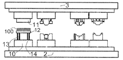
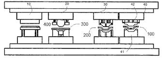
본 개시의 비제한적인 예는 첨부된 도면을 참조하여 다음에서 설명될 것이고, 여기서:
도 1은 실시예에 따라서 다단계 프레스 시스템을 개략적으로 나타내고;
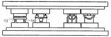
도 2a-2d는 예에 따라서 블랭크를 냉각시키기 위한 방법의 수행 동안 발생하는 상황의 시퀀스를 개략적으로 도시하며;
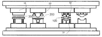
도 2e-2h는 일 실시예에 따라서 동일한 블랭크를 끌어내기 위한 방법의 수행 동안 발생하는 상황의 시퀀스를 개략적으로 도시하고;
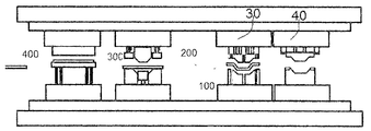
도 2i-2l은 일 실시예에 따라서 동일한 블랭크를 피어싱 및/또는 트리밍하기 위한 방법의 수행 동안 발생하는 상황의 시퀀스를 개략적으로 도시하며;
도 2m-2p는 일 실시예에 따라서 동일한 블랭크를 추가로 피어싱 및/또는 트리밍하기 위한 방법의 수행 동안 발생하는 상황의 시퀀스를 개략적으로 도시한다. Non-limiting examples of this disclosure will be described below with reference to the accompanying drawings, in which:
Figure 1 schematically depicts a multi-stage press system according to an embodiment;
Figures 2a-2d schematically illustrate a sequence of situations occurring during the performance of a method for cooling a blank according to the example;
Figures 2e-2h schematically illustrate a sequence of situations occurring during the performance of a method for deriving the same blank according to an embodiment;
Figures 2i-2l schematically illustrate a sequence of situations occurring during the performance of a method for piercing and / or trimming the same blank, according to one embodiment;
Figures 2m-2p schematically illustrate a sequence of situations that occur during the performance of a method for further piercing and / or trimming the same blank according to one embodiment.
도 1은 일 실시예에 따른 다단계 프레스 시스템을 개략적으로 나타낸다. 시스템(1)은 고정된 하부 몸체(2), 이동식 상부 몸체(3) 및 고정된 하부 몸체(2)에 대해 이동식 상부 몸체(3)의 상향 및 하향 프레스 진행을 제공하도록 구성된 메커니즘(미도시)을 포함한다. Figure 1 schematically depicts a multi-stage press system according to one embodiment. The
고정된 하부 몸체(2)는 대형 금속 블록일 수 있다. 이러한 특정 실시예에서, 고정된 하부 몸체(2)는 정지상태일 수 있다. 일부 실시예에서, 고정된 하부 몸체(2)에 일체화된 다이 쿠션(미도시)이 제공될 수 있다. 쿠션은 블랭크 홀더력을 수용하고 제어하도록 구성될 수 있다. 이동식 상부 몸체(3)는 또한 고형 금속의 조각일 수 있다. 이동식 상부 몸체(3)는 스트로크 사이클(상향 및 하향 움직임)을 제공할 수 있다.The fixed
프레스 시스템은 대략적으로 분당 30 스트로크를 수행하도록 구성될 수 있고, 따라서 각각의 스트로크 사이클은 대략적으로 2초일 수 있다. 스트로크 사이클은 또 다른 실시예에서 다를 수 있다.The press system can be configured to perform roughly 30 strokes per minute, and thus each stroke cycle can be approximately 2 seconds. The stroke cycle may be different in another embodiment.
프레스 메커니즘은 기계적으로, 유압식으로 또는 서보 기계로 구동될 수 있다. 고정된 하부 몸체(2)에 대해 이동식 상부 몸체(3)의 진행은 메커니즘에 의해 결정될 수 있다. 이러한 특정 실시예에서, 프레스는 서보 기계적 프레스일 수 있고, 따라서 스트로크 동안 일정한 프레스력이 제공될 수 있다. 서보 기계적 프레스에는 무한 슬라이드(램) 속도 및 위치 제어가 제공될 수 있다. 서보 기계적 프레스에는 또한 어느 슬라이드 위치에서든 양호한 범위의 프레스력의 가용성이 제공될 수 있고, 따라서 큰 프레스 유연성이 달성될 수 있다. 서보 구동 프레스는 금속 성형에서 공정 조건 및 생산성을 개선할 능력을 가질 수 있다. 프레스는 예를 들어, 2000 Tn의 프레스력을 가질 수 있다.The press mechanism can be driven mechanically, hydraulically or by a servo machine. The progress of the movable
일부 실시예에서, 프레스는 기계적 프레스일 수 있고, 따라서 고정된 하부 몸체(2)를 향한 프레스력 진행은 구동 및 힌지 시스템에 의존할 수 있다. 그러므로 기계적 프레스는 단위시간당 더 높은 사이클에 도달할 수 있다. 대안적으로, 유압식 프레스 역시 사용될 수 있다. In some embodiments, the press may be a mechanical press, and thus the progress of the press force toward the fixed
이전에 가열된 블랭크를 냉각시키도록 구성된 냉각툴(10)이 도 1에 도시된다. 냉각툴(10)은 상부 상대 다이(11) 및 하부 상대 다이(12)를 포함할 수 있다. 각각의 다이는 사용시에 열간 성형 블랭크(미도시)를 마주하는 상부 작업면(15) 및 하부 작업면(16)을 포함할 수 있다.A
하부 다이(12)는 하부 몸체(2)로부터 미리결정된 제 1 거리에서의 위치로 하부 다이(12)를 편향하도록 구성된 제 1 하부 편향 부재(13) 및 제 2 하부 편향 부재(14)를 갖는 하부 몸체(2)에 연결될 수 있다. 일부 실시예에서, 단일 하부 편향 부재가 제공될 수 있고, 또는 2개 이상의 하부 편향 부재가 제공될 수 있다. 편향 부재는 일부 다른 편향 부재 예를 들어, 유압 메커니즘이 가능할 수 있음에도, 예를 들어, 스프링, 예를 들어, 기계적 스프링 또는 가스 스프링을 포함할 수 있다.The
미도시된 일부 다른 실시예에서, 상부 다이(11)는 또한 상부 몸체로부터 미리결정된 제 2 거리에서의 위치에 상부 다이를 편향하도록 구성된 하나 이상의 상부 편향 부재를 갖는 상부 몸체(3)에 연결될 수 있다.In some other embodiments not shown, the
상부 및/또는 하부 편향 부재의 삽입으로, 상부 다이(11)와 하부 다이(12) 사이의 접촉 시간이 스트로크 사이클(하부 몸체(2)에 대해 이동식 상부 몸체(3)의 상향 및 하향 움직임) 동안 조절될 수 있고 증가될 수 있다.With the insertion of the upper and / or lower deflecting member, the contact time between the
냉각툴에서 편향 부재로 인해, 상부 및 하부 냉각 다이 사이의 접촉이 성형 툴(및 또한 하류에 배열된 툴)의 프레스 다이의 접촉 전에 생성될 수 있다. 따라서, 스트로크 사이클 동안 냉각 다이 사이의 접촉 시간이 증가될 수 있어서 더 많은 냉각을 허용한다. Due to the biasing member in the cooling tool, contact between the upper and lower cooling dies can be created prior to contact of the press die of the molding tool (and also the tool arranged downstream). Thus, the contact time between the cooling dies during the stroke cycle can be increased allowing more cooling.
상부 상대 다이(11) 및 하부 상대 다이(12)는 다이에 제공된 채널을 통과하는 차가운 유체 예를 들어, 물 및/또는 차가운 압축된 공기를 갖는 채널(미도시)을 포함할 수 있다.The upper and
부가적으로, 냉각툴(10)은 고온의 액체를 유도하는 하나 이상의 히터 또는 채널 및 다이의 온도를 제어하기 위한 온도 센서를 포함할 수 있다. 더 높은 온도에서 작동하는 다이를 적응하기 위한 다른 대안, 예를 들어, 내장형 카트리지 히터 역시 예측될 수 있다. 이것은 다른 두께의 블랭크, 즉, 지나치게 빠르게 냉각될 수 있는 매우 얇은 블랭크와 작동하는 것을 허용할 수 있고, 따라서 냉각툴의 유연성이 개선될 수 있다. 센서는 열전대일 수 있다.Additionally, the
또한, 상부 상대 다이(11) 및/또는 하부 상대 다이(12)에는 각기 각각의 다이에 상응하여 배열된 냉각 시스템을 포함하는 상부 작업면(15) 및/또는 하부 작업면(16)에 대향하는 표면에 위치될 수 있는 냉각판(미도시)이 제공될 수 있다. 냉각 시스템은 냉각툴의 가열을 회피하거나 또는 적어도 감소시키기 위해 또는 냉각툴에 추가 냉각을 제공하기 위해 차가운 물 또는 임의의 다른 냉각 유체의 순환을 위한 냉각 채널을 포함할 수 있다.It should also be appreciated that the upper and / or lower relative die 11 and / or lower relative die 12 may each have an upper working
실시예에서, 냉각툴에는 센터링 부재, 예를 들어, 핀 및/또는 유도 디바이스가 제공될 수 있다.In an embodiment, the cooling tool may be provided with a centering member, for example a pin and / or an inductive device.
블랭크를 성형하거나 또는 끌어내도록 구성된 프레스툴(20) 역시 본 실시예에 제공된다. 프레스툴(20)은 냉각툴(10)로부터 하류에 배열된다. 프레스툴(20)은 상부 상대 다이(21) 및 하부 상대 다이(22)를 포함한다.A
상부 다이(21)는 사용시에 열간 성형 블랭크를 마주하는 상부 작업면(23)을 포함할 수 있다. 하부 다이(22)는 사용시에 열간 성형 블랭크를 마주하는 하부 작업면(24)을 포함할 수 있다. 상부 작업면(23)에 대향하는 상부 다이의 일 측면은 상부 몸체(3)에 고정될 수 있고 하부 작업면(22)에 대향하는 하부 다이의 일 측면은 하부 몸체(2)에 고정될 수 있다. The
상부 상대 다이(21) 및 하부 상대 다이(22)는 다이에 제공된 채널을 통해 흐르는 차가운 유체, 예를 들어, 물 및/또는 차가운 공기를 갖는 채널을 포함할 수 있다. 수로에서, 채널에서의 물의 순환 속도는 높을 수 있고, 따라서 수증기가 회피될 수 있다. 제어 시스템이 더 제공될 수 있고, 따라서 다이의 온도가 제어될 수 있다.The upper counterpart die 21 and lower counterpart die 22 may comprise channels having cold fluid, e.g., water and / or cold air, flowing through the channels provided in the die. In the channel, the circulation rate of water in the channel can be high, and thus water vapor can be avoided. A control system can be further provided, and thus the temperature of the die can be controlled.
실시예에서, 프레스 시스템(20)에는 하부 다이(22) 상에 블랭크를 유지하고 블랭크를 위치시키도록 구성된 블랭크 홀더(25)가 제공될 수 있다. 블랭크 홀더에는 또한 하부 다이(22)로부터 미리결정된 거리에서의 위치에 블랭크 홀더를 편향하도록 구성된 하나 이상의 편향 부재가 제공될 수 있다.In an embodiment, the
트리밍 및/또는 피어싱 작업을 수행하도록 구성된 제 1 동작후 툴(30)이 제공될 수 있다. 제 1 동작후 툴(30)은 프레스툴(20)의 하류에 배열될 수 있다. 제 1 동작후 툴(30)은 상부 상대 다이(32) 및 하부 상대 다이(31)를 포함할 수 있다. 상부 상대 다이(32)는 상부 작업면(33)을 포함할 수 있고 하부 상대 다이(31)는 하부 작업면(34)을 포함할 수 있다. 사용 시에 양 작업면은 블랭크를 마주한다. A
상부 작업면(33)에 대향하는 상부 다이(32)의 일 측면은 상부 몸체(3)에 고정될 수 있고 하부 작업면(34)에 대향하는 하부 다이(31)의 일 측면은 하부 몸체(2)에 고정될 수 있다. 다이는 작업면 상에 배열된 하나 이상의 나이프 또는 커팅 블레이드(미도시)를 포함할 수 있다.One side of the
제 1 동작후 툴(30)은 고온의 액체를 유도하는 하나 이상의 전기 히터 또는 채널 및 다이의 온도를 제어하는 온도 센서를 포함할 수 있다. 센서는 열전대일 수 있다. 일부 실시예에서, 미리결정된 온도, 예를 들어, 200℃ 이상에서 또는 부근에서 사용될 때 상부 다이와 하부 다이 사이에 위치된 블랭크의 온도를 유지하는 것이 바람직할 수 있다.After the first operation, the
200℃에서 또는 부근에서 0.22% C, 1.2% Si, 2.2% Mn 및 또 다른 요소를 포함하는 아연 코팅을 갖는 블랭크의 강도는 블레이드에서 손상을 회피하기 위한 제한일 수 있는 약 800MPa일 수 있다. 이 방식으로, 200℃ 이상의 온도를 유지하는 것은 커팅 블레이드에서 손상을 회피할 수 있다. 온도를 유지하기 위한 일부 다른 제어 역시 구현될 수 있음에도 제어는 온-오프 제어일 수 있다. The strength of a blank with a zinc coating comprising 0.22% C, 1.2% Si, 2.2% Mn and another element at or near 200 ° C may be about 800 MPa, which may be a limitation to avoid damage in the blade. In this way, maintaining a temperature of 200 DEG C or higher can avoid damage to the cutting blade. The control may be an on-off control, although some other control for maintaining the temperature may also be implemented.
일부 실시예에서, 상부 상대 다이(32) 및 하부 상대 다이(31)는 다이에 제공된 채널을 통과하는 차가운 유체, 예를 들어, 물 및/또는 냉기를 갖는 채널을 포함할 수 있다. In some embodiments, the upper relative die 32 and lower relative die 31 may comprise a channel having cold fluid, e.g., water and / or cold air, passing through the channels provided in the die.
실시예에서, 제 1 동작후 툴(30)에는 하부 다이(31) 상에 블랭크를 유지하고 블랭크를 위치시키도록 구성된 블랭크 홀더(미도시)가 제공될 수 있다. 블랭크 홀더에는 또한 하부 다이로부터 미리결정된 거리에서의 위치에 블랭크 홀더를 편향하도록 구성된 하나 이상의 편향 부재가 제공될 수 있다. In an embodiment, after the first operation, the
제 2 동작후 툴(40)이 제공될 수 있다. 제 2 동작후 툴(40)은 또한 또 다른 트리밍 및/또는 피어싱 동작을 수행하도록 구성될 수 있다. 제 2 동작후 툴(40)은 제 1 동작후 툴(30)의 하류에 배열될 수 있다. 제 2 동작후 툴(40)은 상부 상대 다이(42) 및 하부 상대 다이(41)를 포함할 수 있다. 상부 상대 다이(42)는 상부 작업면(43)을 포함할 수 있고 하부 상대 다이(41)는 하부 작업면(44)을 포함할 수 있다. 사용시에 작업면 모두는 열간 성형 블랭크를 마주할 수 있다. 작업면은 고르지 않을 수 있다, 예를 들어, 그들은 돌출부 또는 리세스를 포함할 수 있다.The
프레스툴(40)에서 다이는 열간 성형 블랭크와는 다른 온도를 가질 수 있고, 따라서 팽창이 고려될 수 있다. 이 방식으로, 다이는 평형을 위해 열간 성형 블랭크보다 2% 더 높을 수 있다.In the
작업면(43)에 대향하는 상부 다이(42)의 일 측면은 상부 몸체(3)에 고정될 수 있다. 작업면(44)에 대향하는 하부 다이(41)의 일 측면은 하부 몸체(2)에 고정될 수 있다.One side of the
다이는 작업면 상에 배열된 하나 이상의 나이프 또는 커팅 블레이드를 포함할 수 있다.The die may include one or more knives or cutting blades arranged on the work surface.
일부 실시예에서, 상부 다이(42) 및 하부 다이(41) 사이의 거리를 조절하도록 구성된 조절 디바이스(미도시)가 제공될 수 있다. 이 방식으로, 사용할 때 상부 다이(42)와 하부 다이(41) 사이에 위치된 블랭크가 각각의 상부 및 하부 다이의 작업면을 따라 변형될 수 있다. In some embodiments, a conditioning device (not shown) configured to adjust the distance between the
변형하기 위해(그리고 따라서 블랭크를 교정하기 위해) 상부 다이(42)와 하부 다이(41) 사이의 거리의 조절이 수행되면, 열간 성형 블랭크의 공차가 개선될 수 있다. 일부 실시예에서, 열간 성형 블랭크는 비최적화된 두께, 예를 들어, 일부 다른 부분에서보다 블랭크의 일부에서 더 큰 두께를 갖는 영역을 가질 수 있고, 따라서 두께는 최적화되어야만 한다.If adjustment of the distance between the
고르지 않은 작업면의 배열로, 작업면의 선택된 부분에서의 거리(예를 들어, 블랭크에서 반경 부근)는 비최적화된 두께를 갖는 영역에서 또는 부근에서 조절될 수 있고, 따라서 소재는 변형될 수 있다, 즉, 비최적화된 두께를 갖는 영역에 인접한 구역으로 흐르도록 가압될 수 있고, 따라서 블랭크를 따른 일정한 두께가 얻어질 수 있다. With an array of uneven work surfaces, the distance in a selected portion of the work surface (e.g., in the vicinity of the radius in the blank) can be adjusted in or near the region having a non-optimized thickness, I.e., to a region adjacent to the region having a non-optimized thickness, so that a constant thickness along the blank can be obtained.
실시예에서, 조절 디바이스는 블랭크의 두께를 검출하도록 구성된 센서 시스템에 기반해서 제어될 수 있다.In an embodiment, the conditioning device can be controlled based on a sensor system configured to detect the thickness of the blank.
일부 실시예에서, 제 2 동작후 툴(40)에는 하부 다이(41) 상에 블랭크를 유지하고 블랭크를 위치시키도록 구성된 블랭크 홀더(미도시)가 제공될 수 있다. 블랭크 홀더에는 또한 하부 다이로부터 미리결정된 거리에서의 위치로 블랭크 홀더를 편향하도록 구성된 하나 이상의 편향 부재가 제공될 수 있다.In some embodiments, after the second operation, the
또 다른 예에서, 더 낮거나 더 높은 온도에서 동작하는 툴의 다이를 적응하는 다른 방식 역시 예측될 수 있다.In another example, other ways of adapting the die of a tool operating at lower or higher temperatures can also be predicted.
도면이 실질적으로 사각형 또는 직사각형 형상을 갖는 다이를 설명함에도, 블록은 임의의 다른 형상을 가질 수 있고 심지어 부분적으로 둥근 형상을 가질 수 있다는 것이 이해될 수 있다.Although the drawings illustrate a die having a substantially rectangular or rectangular shape, it is to be understood that the block may have any other shape and may even have a partially rounded shape.
자동 이송장치(미도시), 예를 들어, 복수의 산업 로봇 또는 컨베이어 역시 툴 사이에 블랭크의 이동을 수행하도록 제공될 수 있다. An automatic transfer device (not shown), for example, a plurality of industrial robots or conveyors, may also be provided to perform the movement of the blank between the tools.
모든 실시예에서, 온도를 제어하기 위한 온도 센서 및 제어 시스템이 임의의 툴에 또는 이동 시스템에 제공될 수 있다. 툴에는 또 다른 냉각 시스템, 블랭크 홀더 등이 제공될 수 있다.In all embodiments, a temperature sensor and a control system for controlling the temperature may be provided in any tool or in a mobile system. The tool may be provided with another cooling system, blank holder or the like.
도 2a-2d는 일 실시예에 따른 블랭크를 냉각시키기 위한 방법의 수행 동안 발생하는 상황의 시퀀스를 개략적으로 도시한다. 동일한 도면 부호는 동일한 부재를 나타낸다. 방법은 도 2a-2d에 의해 도시된 상황의 시퀀스를 참조하여 아래에 설명된다.Figures 2a-2d schematically illustrate a sequence of situations occurring during the performance of a method for cooling a blank according to an embodiment. The same reference numerals denote the same members. The method is described below with reference to the sequence of situations illustrated by Figures 2a-2d.
단순함을 위해서, 각도에 대한 참조는 종종 도 2a(및 또 다른 도면)에 관련한 설명에 포함된다. 각도에 대한 참조는 하부 몸체에 대한 상부 몸체의 근사 위치를 나타내도록 사용될 수 있다. 따라서, 예를 들어, 상부 몸체가 하부 몸체에 대해 최고 위치에 있음을 나타내는 하부 몸체에 대해 0° 위치 및 상부 몸체가 하부 몸체에 대해 최저 위치(완전한 접촉 위치)에 있다는 것을 나타내는 180° 위치에 있다는 것에 대해 참조가 이루어질 수 있다. 그런 후에 360°가 상부 몸체가 최고 위치에 있다는 것을 다시 말한다.For simplicity, references to angles are often included in the description relating to FIG. 2A (and another drawing). The reference to the angle can be used to indicate the approximate position of the upper body relative to the lower body. Thus, for example, it can be seen that the upper body is at a 0 [deg.] Position relative to the lower body indicating that the upper body is in an upper position relative to the lower body and a 180 [deg.] Position indicating that the upper body is in the lowest position (full contact position) References can be made to. Then again 360 ° indicates that the upper body is in the highest position.
도 2a에서, 아연 코팅을 갖는 초고장력강(UHSS)으로 구성된 열간 성형 블랭크(100)가 제공될 수 있다. 일부 실시예에서, UHSS는 예를 들어, 대략적으로 0.22% C, 1.2% Si, 2.2% Mn을 포함할 수 있다. Si 및 Mn의 양은 실온에서 블랭크를 경화하는 것을 가능하게 할 수 있고, 따라서 퀀칭이 회피될 수 있다(그리고 따라서 블랭크 제조 프레스 시간이 감소될 수 있다). 게다가, 퀀칭 단계를 위한 추가 냉각의 다이는 냉각 동안 닫힌 채로 남아있지 않기 때문에 프레스 스트로크 사이클 역시 감소될 수 있다. 소재는 다른 비율로 Mn, Al, Ti, B, P, S, N을 더 포함할 수 있다.In Fig. 2a, a hot-formed blank 100 constructed from ultra-high tensile steel (UHSS) having a zinc coating can be provided. In some embodiments, the UHSS may comprise, for example, approximately 0.22% C, 1.2% Si, 2.2% Mn. The amounts of Si and Mn can make it possible to cure the blank at room temperature, and therefore quenching can be avoided (and hence the blank press time can be reduced). In addition, since the additional cooling die for the quenching step is not left closed during cooling, the press stroke cycle can also be reduced. The material may further contain Mn, Al, Ti, B, P, S and N at different ratios.
본 발명자는 아연 코팅을 갖는 그러한 초고장력강(UHSS)이 860 내지 870℃, 예를 들어, 위에 언급된 스틸 조성물 Ac3에 있어서 대략적으로 867℃일 수 있는 Ac3 변태점(이하에 "Ac3 포인트"로 언급되는 오스테나이트 변태점)을 가질 수 있다. Ms 변태점(이하에, "Ms 포인트"로 언급되는 마텐자이트 출발 온도)은 380 내지 390℃일 수 있다. 위에 언급된 스틸 조성물에 있어서, Ms는 대략적으로 386℃일 수 있다. Mf 변태점(이하에 "Mf 포인트"로 언급되는 마텐자이트 최종 온도)은 270℃에 또는 부근에 있을 수 있다.The present inventors have found that such ultra high tensile steels (UHSS) with zinc coatings can have an Ac3 transformation point (hereinafter referred to as "Ac3 point") which can be from 860 to 870 DEG C, for example approximately 867 DEG C for the steel composition Ac3 mentioned above Austenite transformation point). The Ms transformation point (hereinafter, the martensitic starting temperature referred to as "Ms point ") may be 380 to 390 ° C. In the above-mentioned steel composition, Ms can be approximately 386 ° C. The Mf transformation point (the martensitic final temperature, hereinafter referred to as "Mf point") may be at or near 270 [deg.] C.
다른 스틸 조성물이 사용될 수 있다. 특히 EP 2 735 620 A1에 설명된 스틸 조성물이 적합하게 고려될 수 있다. 구체적 참조는 EP 2 735 620의 표 1 및 단락 0016-0021에, 그리고 단락 0067-0079의 고려로 이루어질 수 있다. Other steel compositions may be used. Particularly the steel compositions described in
블랭크(100)는 적어도 오스테나이트화 온도에 도달하기 위해 가열될 수 있다. 가열은 가열 디바이스(미도시), 예를 들어, 퍼니스에서 수행될 수 있다. 이러한 특정 실시예에서, 블랭크를 가열하는 최대 온도가 코팅에 의해 결정될 수 있다. 아연의 용융점(그리고 따라서 기화 온도)은 910℃에 또는 부근에 있을 수 있고, 따라서 가열 디바이스에서 블랭크(100)를 가열하는 최대 온도가 대략적으로 910℃ 이하로 설정될 수 있다. 이 방식으로, 블랭크(100)는 Ac3보다 더 높지만 910℃에서 또는 부근에서의 아연의 기화 온도보다 더 낮은 온도로 가열될 수 있다. 따라서 가열은 867℃ 내지 910℃, 바람직하게 890℃에서 또는 부근에서 수행될 수 있다. 가열되는 시간의 기간은 대략적으로 6분일 수 있지만, 그것은 예를 들어, 블랭크의 두께에 따른다. The blank 100 may be heated to reach at least the austenitizing temperature. Heating may be performed in a heating device (not shown), e.g., a furnace. In this particular embodiment, the maximum temperature at which the blank is heated may be determined by the coating. The melting point of zinc (and thus the vaporization temperature) may be at or near 910 ° C, so that the maximum temperature at which the blank 100 is heated in the heating device may be set at approximately 910 ° C or lower. In this way, the blank 100 can be heated to a temperature higher than Ac3 but lower than the vaporization temperature of zinc at or near 910 占 폚. Thus, heating can be performed at 867 캜 to 910 캜, preferably at or near 890 캜. The duration of the heating time can be approximately 6 minutes, but it depends, for example, on the thickness of the blank.
블랭크(100)가 본 도면에 미도시된 소망되는 온도로 가열되면, 블랭크(100)는 냉각툴(10)로 이동될 수 있다. 이것은 자동 이송장치(미도시), 예를 들어, 복수의 산업 로봇 또는 컨베이어에 의해 수행될 수 있다. 퍼니스(미도시)와 냉각툴(10) 사이에 블랭크를 이동하는 시간의 기간은 2 내지 3초일 수 있다.When the blank 100 is heated to a desired temperature not shown in the figure, the blank 100 can be moved to the
일부 실시예에서, 센터링 부재, 예를 들어, 핀 및/또는 유도 디바이스가 냉각툴 상류에 제공될 수 있고, 따라서 블랭크가 적절하게 센터링될 수 있다.In some embodiments, a centering member, e.g., a pin and / or inductive device, can be provided upstream of the cooling tool, and thus the blank can be properly centered.
프레스 상부 몸체(3)는 프레스 메커니즘을 사용하여 개방 위치(0°위치)에 위치될 수 있다. 블랭크(100)는 상부 다이(11)와 하부 다이(12) 사이에 위치될 수 있다. 일부 실시예에서, 블랭크는 블랭크 홀더 상에 위치될 수 있다. 하부 다이(12)는 제 1 하부 편향 부재(13) 및 제 2 하부 편향 부재(14)를 사용하여 하부 몸체(2)에 대해 미리결정된 거리에서 이동될 수 있다.The press
위에 언급된 바와 같이, 일부 다른 편향 부재, 예를 들어, 유압식 메커니즘이 가능할 수 있음에도 편향 부재는 예를 들어, 스프링, 예를 들어, 기계적 스프링 또는 가스 스프링을 포함할 수 있다. 유압식 메커니즘은 수동 또는 능동 메커니즘일 수 있다.As mentioned above, some other biasing member, for example a biasing mechanism, may be possible, but the biasing member may comprise, for example, a spring, for example a mechanical spring or a gas spring. The hydraulic mechanism may be a manual or an active mechanism.
이 방식으로, 하부 다이(12)(그리고 따라서 하부 다이(12) 상에 위치된 블랭크(100))가 하부 몸체(2)로부터 제 1 미리결정된 위치(하부 다이가 상부 다이에 의해 90°와 150°사이에 접촉될 수 있는 위치)에 위치될 수 있다.In this manner, the lower die 12 (and thus the blank 100 positioned on the lower die 12) is moved from the
도 2b에서, 프레스에는 고정된 하부 몸체에 대해 이동식 상부 몸체의 하향 프로레스 진행이 제공될 수 있고, 따라서 상부 다이(11)가 하부 다이(12)(그리고 따라서 하부 다이 상에 위치된 블랭크)를 향해 이동될 수 있다.In Figure 2b, the press may be provided with a downward processtransition of the movable upper body relative to the fixed lower body, so that the
상부 다이(11)는 제 1 미리결정된 위치(90°내지 150°의 위치)에서 냉각툴 상부 다이(11)와 냉각툴 하부 다이(12) 사이에 위치된 블랭크(100)에 접촉할 수 있다.The
도 2c에서, 블랭크가 90°와 150° 사이에 접촉되면, 상부 다이(11)는 블랭크(100)를 냉각하기 시작할 수 있다. 블랭크를 프레스하는 것에 의해, 제 1 하부 편향 부재 및 제 2 하부 편향 부재가 블랭크(100)를 프레스하고 냉각하는 최종 소망되는 위치(180°위치)가 도달될 때까지 변형될 수 있다.In Fig. 2C, when the blank contacts between 90 and 150 degrees, the
도 2d에서, 최종 소망되는 위치(180°위치)가 도달되면, 프레스 메커니즘에 의한 상부 몸체의 상향 프레스 진행이 제공될 수 있다. 상부 다이와 블랭크 사이의 최종 접촉은 하부 몸체에 대해 상부 몸체(그리고 따라서 상부 다이)의 210°내지 270°의 위치일 수 있다. 제 1 하부 편향 부재(13) 및 제 2 하부 편향 부재(14)는 그들의 본래 위치로 돌아갈 수 있다, 즉, 연장될 수 있다. 이 방식으로, 블랭크(100)가 상부 다이에 의해 최초로 접촉된 이후 시간의 기간 및 최종 접촉, 즉, 블랭크가 냉각되는 시간은 0.33 내지 1초일 수 있다.In Fig. 2d, when the final desired position (180 DEG position) is reached, the upward pressing progress of the upper body by the press mechanism can be provided. The final contact between the upper die and the blank may be at a position between 210 and 270 degrees of the upper body (and thus the upper die) with respect to the lower body. The first lower deflecting
앞서 언급된 바와 같이, 블랭크(100)가 프레스되는 동안, 블랭크는 냉각 기구를 사용하는 것에 의해 냉각될 수 있다. 아연 코팅을 갖는 초고장력강(UHSS)은 프레스툴에서 600℃보다 더 높은 온도에 대해 미세 균열을 나타낼 수 있다. 이 방식으로, 블랭크는 600℃ 이하, 바람직하게 550℃에서 또는 부근에서의 온도로 프레스툴로 이동되기 전에 냉각될 수 있고, 따라서 미세 균열이 감소될 수 있다.As previously mentioned, while the blank 100 is being pressed, the blank can be cooled by using a cooling mechanism. Ultra High Strength Steel (UHSS) with zinc coating can exhibit microcracking at temperatures higher than 600 ° C in a press tool. In this manner, the blank can be cooled before it is transferred to the press tool at a temperature of 600 占 폚 or less, preferably at or near 550 占 폚, and thus microcracks can be reduced.
블랭크(100)가 890℃에서 또는 부근에서 미리 가열될 수 있다, 즉, 퍼니스에서 가열될 수 있다는 것이 이미 언급되었다. 블랭크는 냉각툴(10)로 이동될 수 있고, 따라서 이동 기간 동안 온도는 750℃ 내지 850℃로 감소될 수 있다. 이러한 배열로, 블랭크(100)는 750℃ 내지 850℃의 냉각툴(10)에 위치될 수 있다. 그런 후에 블랭크는 570℃에서 또는 부근에서의 온도로 냉각될 수 있다. 이것은 200 내지 800℃/s, 일부 실시예에서 500℃/s에서 또는 부근에서의 냉각 속도로 유도할 수 있다.It has already been mentioned that the blank 100 can be preheated at or near 890 DEG C, i.e., heated in the furnace. The blank can be moved to the
프레스 시스템(3)에 일체화된 냉각툴(10)로, 외부 냉각툴로부터 블랭크를 이동하기 위한 추가 움직임이 회피될 수 있기 때문에 블랭크를 냉각하기 위한 시간은 최적화될 수 있다. 그것은 또한 시간 절약일 수 있다. 또한, 툴 사이의 블랭크의 움직임이 제한될 수 있고, 따라서 냉각 속도가 용이하게 제어된다.With the
도 2e-2h는 실시예에 따른 블랭크를 끌어내기 위한 방법의 수행 동안 발생하는 상황의 시퀀스를 개략적으로 도시한다. 동일한 도면 부호는 동일한 부재를 나타낸다. 그 방법은 도 2e-2h에 의해 도시된 상황의 시퀀스를 참조하여 아래에 설명된다.Figures 2e-2h schematically illustrate a sequence of situations occurring during the performance of a method for drawing a blank according to an embodiment. The same reference numerals denote the same members. The method is described below with reference to the sequence of situations illustrated by Figures 2e-2h.
도 2e에서, 블랭크(100)는 미리 냉각될 수 있고, 따라서 블랭크(100)는 냉각툴(10)로부터 프레스툴(20)로 이동될 준비가 될 수 있다. 이동은 자동 이송장치(미도시), 예를 들어, 복수의 산업 로봇 또는 컨베이어에 의해 수행될 수 있다. 위에 언급된 바와 같이, 블랭크는 570℃에서 또는 부근에서의 온도에서 이동될 수 있다. 이동 시간으로 인해, 블랭크(100)는 성형 툴에 도달할 때 550℃에서 또는 부근에서 냉각될 수 있다. 블랭크(100)는 블랭크 홀더를 사용하여 하부 다이(22) 상에 이송장치에 의해 위치될 수 있다. 일부 실시예에서, 프레스 하부 다이(22)에 대한 블랭크 홀더의 거리는 하나 이상의 편향 부재를 사용하여 조절될 수 있다.In FIG. 2E, the blank 100 can be pre-cooled, and thus the blank 100 can be ready to be moved from the
이송장치가 동일한 프레스 시스템에 일체화될 수 있기 때문에, 이동 시간이 짧고, 온도 제어가 양호하다.Since the transfer device can be integrated into the same press system, the transfer time is short and the temperature control is good.
블랭크(100)가 하부 다이(22) 상에 이동되고 위치되는 동안, 자동 이동 시스템은 블랭크(200)를 냉각툴(10)에 제공하도록 작동될 수 있다. 결과적으로, 냉각툴(10)은 블랭크를 냉각하도록 동작을 시작할 수 있다. 이러한 동작은 이전에 언급된 바와 같이 수행될 수 있다. 또한, 이러한 동작은 프레스툴(20)의 동작과 동시에 수행될 수 있다.While the blank 100 is being moved and positioned on the
이 방식으로, 프레스 상부 몸체(3)는 프레스 메커니즘을 사용하여 개방 위치(0°위치)에 다시 위치될 수 있다. 블랭크(100)는 프레스툴 상부 다이(21)와 프레스툴 하부 다이(22) 사이에 위치될 수 있다.In this way, the press
도 2f에서, 프레스(1)에는 고정된 하부 몸체(2)에 대해 이동식 상부 몸체(3)의 하향 프레스 진행이 제공될 수 있고, 따라서 상부 다이(21)는 하부 다이(22)를향해 이동될 수 있다.In Figure 2f the
도 2g에서, 상부 다이(21)는 대략적으로 180°위치에서 프레스툴 상부 다이(21)와 프레스툴 하부 다이(22) 사이에 위치된 블랭크(100)를 접촉할 수 있다. 블랭크가 접촉되면, 상부 다이(21)는 블랭크(100)를 프레스하고 끌어내기 시작할 수 있다. In Fig. 2G, the
도 2h에서, 최종 소망되는 위치가 도달되면, 상향 프레스 진행이 제공될 수 있다. 성형 툴의 상부 다이의 작업면과 블랭크 사이의 최종 완전한 접촉(그리고 따라서 끌어내는 동작의 끝)은 180°내지 210° 위치에 있을 수 있다. 블랭크와 블랭크 홀더 사이의 최종 접촉은 예를 들어, 210°-270°사이에 있을 수 있다.In Fig. 2h, when the final desired position is reached, an upward press run can be provided. The final complete contact between the work surface of the upper die of the forming tool and the blank (and thus the end of the pulling motion) may be in the 180 ° to 210 ° position. The final contact between the blank and the blank holder may be between 210 [deg.] And 270 [deg.], For example.
블랭크(100)의 온도는 300℃에서 또는 부근에서의 온도가 도달될 때까지 감소될 수 있다. 프레스툴에는 냉각 시스템이 제공될 수 있다. 냉각 시스템은 제어기에 의해 제어될 수 있고, 따라서 블랭크(100)의 온도는 소망되는 온도에서 감소되고 유지될 수 있다.The temperature of the blank 100 may be reduced until a temperature at or near 300 [deg.] C is reached. The press tool may be provided with a cooling system. The cooling system can be controlled by the controller, and thus the temperature of the blank 100 can be reduced and maintained at the desired temperature.
동시에, 블랭크(200)는 냉각 시스템(10)을 사용하여 프레스되고 냉각될 수 있다. 블랭크(200)와 냉각툴(10)의 동작은 위에 언급된 바와 같이 동일할 수 있다.At the same time, the blank 200 can be pressed and cooled using the
도 2i-2l은 일 실시예에 따라서 동일한 블랭크를 피어싱 및/또는 트리밍하기 위한 방법의 수행 동안 발생하는 상황의 시퀀스를 개략적으로 도시할 수 있다. 동일한 도면 부호는 동일한 부재를 나타낸다. 그 방법은 도 2i-2l에 의해 도시된 상황의 시퀀스를 참조하여 아래에 설명된다.Figures 2i-2l may schematically illustrate a sequence of situations that occur during the performance of a method for piercing and / or trimming the same blank, according to one embodiment. The same reference numerals denote the same members. The method is described below with reference to a sequence of situations illustrated by Figures 2i-2l.
도 2i에서, 블랭크(100)는 또한 미리 끌어내지고, 따라서 블랭크(100)는 프레스툴(20)로부터 제 1 동작후 툴(30), 예를 들어, 피어싱 또는 트리밍 동작 툴로 이동될 준비가 될 수 있다. 이동이 자동 이송장치(미도시), 예를 들어, 복수의 산업 로봇 또는 컨베이어에 의해 수행될 수 있다. 위에 언급된 바와 같이, 블랭크(100)는 프레스툴(20)을 떠날 수 있고 300℃에서 또는 부근에서의 온도에서 이동될 수 있다. 이동 시간으로 인해, 블랭크(100)는 280℃에서 또는 부근에서 냉각될 수 있고, 따라서 이러한 온도에서 제 1 동작후 툴에 위치될 수 있다. 블랭크(100)는 하부 다이(31) 상에 그리고 하부 다이(31)와 상부 다이(32) 사이에 위치될 수 있다.2I, the blank 100 is also pulled in advance so that the blank 100 is ready to be moved from the
도 2j에서, 블랭크(100)가 하부 다이(31) 상에 이동되고 위치될 때, 자동 이동 시스템은 프레스툴(20)에 블랭크(200)를 제공하도록 그리고 냉각툴(10)에 블랭크(300)를 제공하도록 동작될 수 있다.2J, when the blank 100 is moved and positioned on the
결과적으로, 냉각툴(10)은 위에 언급된 바와 같이 블랭크(300)를 프레스하고 냉각하도록 동작을 시작할 수 있다. 동시에, 프레스툴(20)은 역시 위에 언급된 바와 같이, 블랭크(300)를 끌어내고 냉각하도록 동작을 시작할 수 있다.As a result, the
이러한 방식으로, 프레스 상부 몸체(32)는 프레스 메커니즘을 사용하여 개방 위치(0°위치)에 위치될 수 있다. 프레스(1)에는 고정된 하부 몸체(2)에 대해 이동식 상부 몸체(3)의 하향 프레스 진행이 제공될 수 있고, 따라서 상부 다이(32)는 하부 다이(31)를 향해 이동될 수 있다.In this way, the press
도 2k에서, 상부 다이(32)는 최종 소망되는 위치(180°에서 또는 부근에서)가 도달될 때까지 프레스툴 상부 다이(31)와 프레스툴 하부 다이(31) 사이에 위치된 블랭크(100)에 접촉할 수 있다.2K, the
프레스가 블랭크(100)와 접촉하는 동안, 피어싱 동작이 커팅 블레이드 또는 일부 다른 커팅 부재를 사용하여 수행될 수 있다. 피어싱 동작이 끝나면, 트리밍 동작이 수행될 수 있다. 대안적인 실시예에서, 트리밍 동작이 처음으로 수행될 수 있고 트리밍 동작이 끝나면 트리밍 동작이 수행될 수 있다.While the press is in contact with the blank 100, the piercing operation can be performed using a cutting blade or some other cutting member. When the piercing operation is completed, a trimming operation can be performed. In an alternative embodiment, a trimming operation may be performed for the first time and a trimming operation may be performed when the trimming operation is finished.
블랭크(100)가 동작후를 겪는 동안, 블랭크는 위에 언급된 가열 기구를 사용하는 것에 의해 가열될 수 있다. 200℃에서 또는 부근에서 아연 코팅을 갖는 초고장력강(UHSS)은 800MPa에서 또는 부근에서의 강도를 가질 수 있다는 것이 발견되었다. 이것은 동작, 예를 들어, 트리밍 및/또는 피어싱 동작을 수행하기 위해 가능한 최대 강도일 수 있다. 이러한 방식으로, 제어 온도 시스템을 갖는 가열 시스템이 제공될 수 있고, 따라서 블랭크(100)의 온도가 200℃이상으로 유지될 수 있다. 이러한 배열로, 블랭크의 강도가 피어싱 및/또는 트리밍되기에 적정한 값에서 유지될 수 있다.While the blank 100 undergoes the operation, the blank can be heated by using the above-mentioned heating mechanism. It has been found that ultra high tensile steels (UHSS) having a zinc coating at or near 200 DEG C can have strength at or near 800 MPa. This may be the maximum possible intensity to perform the action, e.g., trimming and / or piercing action. In this way, a heating system with a controlled temperature system can be provided, and thus the temperature of the blank 100 can be maintained at 200 DEG C or higher. With this arrangement, the strength of the blank can be maintained at an appropriate value to be pierced and / or trimmed.
도 2l에서, 최종 요구되는 위치(180°위치)가 도달되면, 상향 프레스 진행이 제공될 수 있다. 상부 다이(32)의 작업면과 블랭크(100) 사이의 최종 완전한 접촉(그리고 따라서 동작의 종료)은 180°내지 210°의 위치일 수 있다. 블랭크와 블랭크 홀더 사이의 최종 접촉은 210°내지 270°에서 발생할 수 있다.In FIG. 21, when the final required position (180 DEG position) is reached, an upward press running can be provided. The final complete contact (and thus the end of operation) between the work surface of the
도 2m-2p는 일 실시예에 따라 블랭크를 추가로 피어싱 및/또는 트리밍하기 위한 방법의 수행 동안 발생하는 상황의 시퀀스를 개략적으로 도시한다. 동일한 도면 부호는 동일한 부재를 나타낸다. 그 방법은 도 2m-2p에 의해 도시된 상황의 시퀀스를 참조하여 아래에 설명된다.Figures 2m-2p schematically illustrate a sequence of situations occurring during the performance of a method for further piercing and / or trimming a blank according to one embodiment. The same reference numerals denote the same members. The method is described below with reference to the sequence of situations illustrated by Figures 2m-2p.
도 2m에서, 블랭크(100)는 제 1 동작후 툴(30)로부터 제 2 동작후 툴(40), 예를 들어, 트리밍 및 교정 툴로 이동될 수 있다. 이동은 자동 이송장치(미도시), 예를 들어, 복수의 산업적 로봇 또는 컨베이어에 의해 수행될 수 있다. 앞서 언급된 바와 같이, 블랭크(100)는 제 1 동작후 툴(30)을 떠날 수 있고 200℃에서 또는 부근에서의 온도에서 이동될 수 있다.In Figure 2M, the blank 100 may be moved from the
도 2n에서, 블랭크(100)는 예를 들어, 블랭크 홀더를 사용하여 하부 다이(41) 상에 위치될 수 있다. 블랭크는 하부 다이(41)와 상부 다이(42) 사이에 위치될 수 있다.In Figure 2n, the blank 100 may be positioned on the
블랭크(100)가 하부 다이(41) 상에 이동되거나 위치되는 동안, 자동 이동 시스템은 블랭크(200)를 제 1 동작후 툴(30)에, 블랭크(300)를 프레스툴(200)에 그리고 블랭크(400)를 냉각툴(10)에 제공하도록 동작될 수 있다. 결과적으로, 냉각툴(10)은 블랭크(400)를 프레스하고 냉각하도록 동작을 시작할 수 있다. 동시에, 프레스툴(20) 및 제 1 동작후 툴(30)은 각각 그들의 동작을 시작할 수 있다. 툴의 동작은 이전에 언급된 것과 동일할 수 있다.While the blank 100 is being moved or positioned on the
도 2o에서, 프레스 상부 몸체(42)는 프레스 메커니즘을 사용하여 개방 위치(0°위치)에 위치될 수 있다. 프레스(1)에는 고정된 하부 몸체(2)에 대해 이동식 상부 몸체(3)의 하향 프레스 진행이 제공될 수 있고, 따라서 상부 다이(42)는 하부 다이를 향해 이동될 수 있다. 상부 다이(42)는 최종 소망되는 위치(하부 몸체에 대해 상부 다이의 180°에서 또는 부근에서)에서 상부 다이(41)와 하부 다이(42) 사이에 위치된 블랭크를 접촉할 수 있다.In Fig. 2O, the press
프레스가 블랭크(100)와 접촉하는 동안, 피어싱 동작이 커팅 블레이드를 사용하여 수행될 수 있다. 피어싱 동작이 종료되면, 트리밍 동작이 수행될 수 있다.대안적인 실시예에서. 트리밍 동작이 처음에 수행될 수 있고 트리밍 동작이 종료되면 트리밍 동작이 수행될 수 있다.While the press is in contact with the blank 100, the piercing operation can be performed using a cutting blade. When the piercing operation is terminated, a trimming operation can be performed. In an alternative embodiment. The trimming operation can be performed at the beginning and the trimming operation can be performed when the trimming operation is finished.
부가적으로, 교정 동작이 수행될 수 있고, 따라서 블랭크의 공차가 제공될 수 있다. 이 방식으로, 상부 다이(42)와 하부 다이(41) 사이의 거리가 조절 디바이스를 사용하여 조절될 수 있다. 조절 디바이스는 블랭크(100)의 두께를 검출하도록 구성된 센서 시스템(미도시)에 기반해서 제어될 수 있다. 실시예에 이어서, 블랭크가 상부 다이(42) 및 하부 다이(41)에 의해 프레스될 수 있고, 따라서 블랭크의 일정한 두께가 얻어질 수 있다.Additionally, a calibration operation can be performed, and thus tolerance of the blank can be provided. In this way, the distance between the
제 2 동작후 툴의 동작이 종료되면, 블랭크(100)가 이동되고 실온에서 경화될 수 있다.When the operation of the tool is terminated after the second operation, the blank 100 can be moved and cured at room temperature.
도 2p에서, 최종 소망되는 위치(180°위치)가 도달되면, 상향 프레스 진행이 제공될 수 있다. 상부 다이(42)의 작업면과 블랭크(100) 사이의 마지막 완전한 접촉(그리고 따라서 제 2 동작의 종료)이 180°와 210°의 위치에 있을 수 있다. 블랭크와 블랭크 홀더 사이의 최종 접촉이 210°와 270°사이에 발생할 수 있다. In Fig. 2P, when the final desired position (180 [deg.] Position) is reached, an upward press advance can be provided. The last complete contact between the work surface of the
개방 위치(0°위치)가 상향 움직임을 적용하는 것에 의해 프레스에 의해 도달되면, 블랭크(100)가 이동되고 실온에서 경화될 수 있다. 동시에, 자동 이동 시스템이 블랭크(500)를 냉각툴(10)에, 블랭크(200)를 제 2 동작후 툴(40)에, 블랭크(300)를 제 1 동작후 툴(30)에 그리고 블랭크(400)를 프레스툴(20)에 제공하도록 동작될 수 있다. 결과적으로, 모든 툴은 이전에 언급된 바와 같이 그들의 동작을 시작할 수 있다.If the open position (0 DEG position) is reached by pressing by applying an upward motion, the blank 100 can be moved and cured at room temperature. At the same time, the automatic moving system moves the blank 500 to the
일부 실시예에서, 블랭크(100)의 형상에 따라서, 또 다른 끌어내는 및 다른 동작, 예를 들어, 피어싱 및/또는 트리밍이 제공될 수 있다. 또 다른 실시예에서, 동작후 순서는 상호교환될 수 있다(예를 들어, 제 1 커팅, 그런 후에 교정 또는 그 반대).In some embodiments, depending on the shape of the blank 100, other pulling and other actions may be provided, for example, piercing and / or trimming. In another embodiment, the post-operation sequence may be interchanged (e.g., first cutting, then calibrating, or vice versa).
완전함의 이유로, 본 개시의 다양한 측면은 다음의 번호 매겨진 이유로 정의된다:For completeness reasons, the various aspects of this disclosure are defined for the following numbered reasons:
항목 1. 열간 성형된 구조적 부품을 제조하기 위한 프레스 시스템, 그 시스템은 고정된 하부 몸체, 이동식 상부 몸체 및 고정된 하부 몸체에 대해 이동식 상부 몸체의 상향 및 하향 프레스 진행을 제공하도록 구성된 메커니즘을 포함하고, 여기서 그 시스템은:
-각각의 냉각 다이가 사용시에 블랭크를 마주하는 하나 이상의 작업면을 포함하는, 상부 및 하부 상대 냉각 다이, 및 Upper and lower relative cooling die, each cooling die comprising at least one work surface facing in use with a blank; and
-하부 몸체로부터 미리결정된 제 1 거리에서의 위치를 향해 하부 냉각 다이를 편향하도록 구성된 하나 이상의 하부 편향 부재를 갖는 하부 몸체에 연결된 하부 냉각 다이 및/또는 상부 몸체로부터 미리결정된 제 2 거리에서의 위치를 향해 상부 냉각 다이를 편향하도록 구성된 하나 이상의 상부 편향 부재를 갖는 상부 몸체에 연결된 상부 냉각 다이, A lower cooling die connected to the lower body having at least one lower deflecting member configured to deflect the lower cooling die toward a position at a predetermined first distance from the lower body and / or a position at a predetermined second distance from the upper body An upper cooling die connected to an upper body having at least one upper deflecting member configured to deflect the upper cooling die toward the lower cooling die,
-를 포함하는 미리 가열된 블랭크를 냉각시키도록 구성된 냉각툴,- a cooling tool configured to cool the preheated blank,
-각각의 프레싱 다이가 사용 시에 블랭크를 마주하는 하나 이상의 작업면을 포함하고, 그리고 Each pressing die comprises at least one working surface facing the blank in use, and
-상부 프레싱 다이는 상부 몸체에 고정되고 그리고 하부 프레싱 다이는 하부 몸체에 고정되는, 상부 및 하부 상대 프레싱 다이 The upper pressing die being fixed to the upper body and the lower pressing die being fixed to the lower body,
-를 포함하고 냉각툴로부터 하류로 배열되며 그리고 블랭크를 끌어내도록 구성된 프레스툴, 및- a press tool arranged to be downstream from the cooling tool and configured to draw the blank, and
-블랭크를 냉각툴로부터 프레스툴로 이동하는 블랭크 이동 메커니즘을 포함한다.And a blank transfer mechanism for transferring the blank from the cooling tool to the press tool.
항목 2. 트리밍 및/또는 피어싱 동작을 수행하도록 구성된 제 1 동작후 툴을 더 포함하는, 항목 1에 따른 시스템, 여기서 상기 제 1 동작후 툴은 프레스툴의 하류에 배열되고 그리고:
-각각의 다이가 사용시에 블랭크를 마주하는 하나 이상의 작업면을 포함하고, - each die includes at least one working surface facing the blank in use,
-상부 제 1 동작후 툴 다이는 상부 몸체에 고정되고 그리고 하부 제 1 동작후 툴 다이는 하부 몸체에 고정되며, 그리고 The tool die is fixed to the upper body after the upper first operation and the tool die is fixed to the lower body after the lower first operation,
-작업면 상에 배열된 하나 이상의 커팅 블레이드를 포함하는, 상부 및 하부 상대 제 1 동작후 툴 다이 및, A tool die after the upper and lower relative first motion, comprising at least one cutting blade arranged on the work surface,
-블랭크를 프레스툴로부터 제 1 동작후 툴로 이동하도록 더 구성된 블랭크 이동 메커니즘을 포함한다. A blank movement mechanism configured to move the blank from the press tool to the tool after the first operation.
항목 3. 트리밍 및/또는 피어싱 동작을 수행하도록 구성된 제 2 동작후 툴을 더 포함하는, 항목 2에 따른 시스템, 상기 제 2 동작후 툴은 제 1 동작후 툴의 하류에 배열되고 그리고:
-각각의 다이가 사용시에 블랭크를 마주하는 하나 이상의 작업면을 포함하고, - each die includes at least one working surface facing the blank in use,
-상부 제 2 동작후 툴 다이는 상부 몸체에 고정되고 그리고 하부 제 1 동작후 툴 다이는 하부 몸체에 고정되며, The tool die is fixed to the upper body after the upper second operation and the tool die is fixed to the lower body after the lower first operation,
-작업면 상에 배열된 하나 이상의 커팅 블레이드를 포함하는, 상부 및 하부 상대 제 2 동작후 툴 다이, 및 A tool die after the upper and lower relative second movements, comprising at least one cutting blade arranged on the work surface, and
-블랭크를 제 1 동작후 툴로부터 제 2 동작후 툴로 이동하도록 더 구성된 블랭크 이동 메커니즘을 포함한다. A blank movement mechanism configured to move the blank from the tool after the first operation to the tool after the second operation.
항목 4. 항목 3에 따른 시스템으로서, 제 2 동작후 툴은 각각의 상부 및 하부 다이의 작업면을 따라 사용시에 제 2 동작후 툴에 위치된 블랭크를 변형하도록 상부 및 하부 다이 사이의 거리를 조절하도록 구성된 조절 디바이스를 포함하고, 상기 조절 디바이스는 블랭크의 두께를 검출하도록 구성된 센서 시스템에 기반해서 제어된다.Item 4. The system according to
항목 5. 항목 1-4 중 어느 하나에 따른 시스템으로서, 제 1 동작후 툴의 다이는 고온의 액체를 유도하는 하나 이상의 히터 또는 채널을 포함한다.Item 5. The system according to any of items 1-4, wherein the die of the tool after the first operation comprises at least one heater or channel for inducing hot liquid.
항목 6. 항목 5에 따른 시스템으로서, 고온의 액체를 유도하는 히터 또는 채널은 다이에서 측정된 온도에 기반해서 200℃ 이상의 블랭크의 온도를 유지하도록 구성된다.Item 6. The system according to item 5, wherein the heater or channel for inducing the hot liquid is configured to maintain a temperature of the blank of 200 DEG C or higher based on the temperature measured at the die.
항목 7. 항목 1-6 중 어느 하나를 청구하는 것에 따른 시스템으로서, 냉각툴의 다이는 고온의 액체를 유도하는 하나 이상의 히터 또는 채널을 포함한다.Item 7. A system according to any one of claims 1-6, wherein the die of the cooling tool comprises at least one heater or channel for inducing a hot liquid.
항목 8. 항목 1-7 중 어느 하나에 따른 시스템으로서, 냉각툴의 다이는 냉각수를 전달하는 채널을 포함한다. Item 8. The system according to any one of items 1-7, wherein the die of the cooling tool includes a channel for delivering cooling water.
항목 9. 항목 1-8 중 어느 하나에 따른 시스템으로서, 냉각툴의 다이는 공기를 전달하는 채널을 포함한다.Item 9. A system according to any of items 1-8, wherein the die of the cooling tool comprises a channel for delivering air.
항목 10. 항목 1-9 중 어느 하나에 따른 시스템으로서, 프레스툴의 다이는 냉각수를 전달하는 채널 및/또는 공기를 전달하는 채널을 포함한다.
항목 11. 항목 1-10 중 어느 하나에 따른 시스템으로서, 제 1 동작후 툴의 다이는 냉각수를 전달하는 채널을 포함한다.
항목 12. 항목 1-11 중 어느 하나에 따른 시스템으로서, 제 1 동작후 툴의 다이는 공기를 전달하는 채널을 포함한다.
항목 13. 항목 1-12 중 어느 하나에 따른 시스템으로서, 냉각 다이 및/또는 프레스 다이 및/또는 제 1 동작후 툴 다이 및/또는 제 2 동작후 툴 다이의 온도는 다이에서 측정된 온도에 기반해서 조절되도록 구성된다.
항목 14. 항목 13에 따른 시스템으로서, 다이는 다이의 온도를 측정하도록 구성된 하나 이상의 열전대를 포함한다.
항목 15. 블랭크를 냉각하기 위한 방법은:
-항목 1-14 중 어느 하나에 따른 프레스 시스템을 제공하는 단계; - providing a press system according to any one of items 1-14;
-아연 코팅을 갖는 초고장력강(UHSS)으로 구성된 열간 성형 블랭크를 제공하는 단계; - providing a hot formed blank comprised of ultra high tensile steel (UHSS) with a zinc coating;
-블랭크를 가열하는 단계; - heating the blank;
-프레스 메커니즘을 사용하여 개방 위치에서 프레스 상부 몸체를 위치시키는 단계; Positioning the upper body of the press at the open position using a press mechanism;
-냉각툴 상부 및 하부 상대 다이 사이에 블랭크를 위치시키는 단계; Positioning a blank between the cooling tool upper and lower mating dies;
-편향 부재를 변형하는 것에 의해 블랭크를 프레스하는 동안 고정된 하부 몸체에 대해 최종 소망되는 위치가 도달될 때까지 상부 다이가 하부 다이를 향해 이동됨으로서 고정된 하부 몸체에 대해 이동식 상부 몸체의 하향 프레스 진행을 제공하는 것에 의해 블랭크를 프레스하고 냉각시키는 단계를 포함한다. The upper die is moved toward the lower die until the final desired position is reached with respect to the fixed lower body during the pressing of the blank by deforming the biasing member so that the lower body of the movable upper body is pressed against the fixed lower body And pressing and cooling the blank.
항목 16. 항목 15에 따른 방법으로서, 블랭크는 860℃ 내지 910℃의 오스테나트화 온도로 가열된다.
항목 17. 항목 15-16 중 어느 하나에 따른 방법으로서, UHSS는 대략적으로 0.22% C, 1.2% Si, 2.2% Mn을 포함한다.Item 17. The method according to any of items 15-16, wherein the UHSS comprises approximately 0.22% C, 1.2% Si, 2.2% Mn.
항목 18. 항목 17에 따른 방법으로서, UHSS는 Mn, Al, Ti, B, P, S, N을 포함한다.Item 18. The method according to item 17, wherein the UHSS comprises Mn, Al, Ti, B, P, S, N.
항목 19. 항목 15-18 중 어느 하나에 따른 방법으로서, 블랭크는 500 내지 600℃의 온도로 냉각된다.Item 19. The method according to any one of items 15-18, wherein the blank is cooled to a temperature of from 500 to 600 < 0 > C.
항목 20. 항목 15-19 중 어느 하나에 따른 방법으로서, 블랭크는 400 내지 600℃/s의 속도에서 냉각된다.
항목 21. 항목 15-20 중 어느 하나에 따른 방법을 포함하는 블랭크를 끌어내기 위한 방법은:
-블랭크를 냉각툴로부터 프레스툴로 이동하는 단계; - moving the blank from the cooling tool to the press tool;
-프레스툴 상부 및 하부 다이 사이에 블랭크를 위치시키는 단계; Placing a blank between the upper and lower die of the press tool;
-구조적 부품을 프레스하는 동안 프레스 고정된 하부 몸체에 대해 최종 소망되는 위치가 도달될 때까지 고정된 하부 몸체에 대해 이동식 상부 몸체의 포워드 프레스 진행을 제공하는 것에 의해 블랭크를 단계를 더 포함한다. - Blanking by providing a forward press advancement of the movable upper body relative to the fixed lower body until the final desired position is reached for the press-fixed lower body during pressing of the structural part.
* *
항목 22. 항목 21에 따른 방법으로서, 동안 블랭크를 냉각시키는 단계를 더 포함한다.
항목 23. 항목 22에 따른 방법으로서, 블랭크는 320℃ 내지 280℃의 온도로 냉각된다.
항목 24. 항목 2에 따를 때 항목 21-23 중 어느 하나에 따른 방법을 포함하는 블랭크를 피어싱 및/또는 트리밍하기 위한 방법은:
-블랭크를 프레스툴로부터 제 1 동작후 툴로 이동시키는 단계; Moving the blank from the press tool to the tool after the first operation;
-제 1 동작후 툴 상부 및 하부 상대 다이 사이에 성형되는 구조적 부품을 위치시키는 단계; Positioning a structural component to be molded between the tool upper and lower mating dies after the first operation;
-블랭크를 프레스하는 동안 프레스 고정된 하부 몸체에 대해 최종 소망되는 위치가 도달될 때까지 프레스 고정된 하부 몸체에 대해 프레스 이동식 상부 몸체의 하향 프레스 진행을 제공하는 단계; - providing a downward pressing progression of the press movable upper body relative to the press-fixed lower body until a final desired position is reached for the press-fixed lower body during the pressing of the blank;
-제 1 동작후 툴의 커팅 블레이드를 사용하는 블랭크를 커팅 및/또는 펀칭하는 단계를 더 포함한다. - cutting and / or punching the blank using the cutting blade of the tool after the first operation.
항목 25. 항목 24에 따른 방법으로서, 제 1 동작후 툴에 위치된 블랭크의 온도는 200℃ 이상에서 유지된다.
항목 26. 항목 3에 따를 때 항목 24-25 중 어느 하나에 따른 방법을 포함하는 성형되는 열간 성형된 구조적 부품을 추가로 피어싱 및/또는 트리밍 및 교정하기 위한 방법은:Item 26. A method for further piercing and / or trimming and calibrating a formed hot-formed structural component comprising the method according to any one of items 24-25 according to
-구조적 부품을 제 1 동작후 툴로부터 제 2 동작후 툴로 이동하는 단계; Moving the structural component from the tool after the first operation to the tool after the second operation;
-구조적 부품을 프레스하는 동안 최종 소망되는 위치가 도달될 때까지 프레스 고정된 하부 몸체에 대해 프레스 이동식 상부 몸체의 하향 프레스 진행을 제공하는 단계; - providing a downward pressing progression of the press movable upper body relative to the press-fixed lower body until a final desired position is reached during pressing of the structural component;
-커팅 블레이드를 사용하여 구조적 부품을 커팅 및/또는 펀칭하는 단계; Cutting and / or punching the structural part using a cutting blade;
-각각의 상부 및 하부 다이의 작업면을 따라 성형되는 구조적 부품을 변형하기 위해 상부 및 하부 다이 사이의 거리를 조절하는 단계를 더 포함한다. - adjusting the distance between the upper and lower dies to deform the structural component to be molded along the working surface of each of the upper and lower dies.
항목 27. 항목 26에 따른 방법에 의해 얻어질 수 있는 바와 같은 열간 성형된 구조적 부품.Item 27. A hot-formed structural component as obtainable by a method according to item 26.
다수의 실시예가 여기에 개시됨에도, 다른 대안, 수정, 용도 및/또는 균등물이 가능하다. 또한, 설명된 실시예의 모든 가능한 조합 역시 포함된다. 따라서, 본 개시의 범위는 특정 실시예에 의해 한정되는 것이 아니라, 이어지는 청구항의 정확한 독해에 의해서만 결정될 수 있다.While many embodiments are disclosed herein, other alternatives, modifications, uses, and / or equivalents are possible. Also, all possible combinations of the described embodiments are also included. Accordingly, the scope of the present disclosure is not to be limited by the specific embodiments, but may be determined only by correct reading of the following claims.
Claims (15)
-각각의 냉각 다이가 사용시에 블랭크를 마주하는 하나 이상의 작업면을 포함하는, 상부 상대 냉각 다이(11) 및 하부 상대 냉각 다이(12), 및
-상기 하부 몸체로부터 미리결정된 제 1 거리에서의 위치를 향해 상기 하부 냉각 다이(12)를 편향하도록 구성된 하나 이상의 하부 편향 부재를 갖는 상기 하부 몸체(2)에 연결된 상기 하부 냉각 다이(12) 및/또는 상부 몸체(3)로부터 미리결정된 제 2 거리에서의 위치를 향해 상기 상부 냉각 다이(11)를 편향하도록 구성된 하나 이상의 상부 편향 부재를 갖는 상기 상부 몸체(3)에 연결된 상기 상부 냉각 다이(11),
-를 포함하는 미리 가열된 블랭크를 냉각시키도록 구성된 냉각툴(10),
-각각의 프레싱 다이가 사용 시에 상기 블랭크를 마주하는 하나 이상의 작업면을 포함하고, 그리고
-상기 상부 프레싱 다이(21)는 상기 상부 몸체(3)에 고정되고 그리고 상기 하부 프레싱 다이(22)는 상기 하부 몸체(2)에 고정되는, 상부 상대 프레싱 다이(21) 및 하부 상대 프레싱 다이(22)
-를 포함하고 상기 냉각툴(10)로부터 하류로 배열되며 그리고 상기 블랭크를 끌어내도록 구성된 프레스툴(20), 및
-상기 블랭크를 상기 냉각툴로부터 상기 프레스툴로 이동하는 블랭크 이동 메커니즘을 포함하는 것을 특징으로 하는 시스템.A press system (1) for manufacturing a thermoformed structural component, the system comprising a fixed lower body (2), a movable upper body (3) and an upper and a lower press A mechanism configured to provide a progress, wherein the system comprises:
- an upper relative cooling die (11) and a lower relative cooling die (12), each cooling die comprising at least one work surface facing in use with a blank; and
- said lower cooling die (12) connected to said lower body (2) having at least one lower deflection member configured to deflect said lower cooling die (12) towards a position at a first predetermined distance from said lower body, (11) connected to the upper body (3) having at least one upper deflecting member configured to deflect the upper cooling die (11) towards a position at a second predetermined distance from the upper body (3) ,
- a cooling tool (10) configured to cool a preheated blank containing the blank,
Each pressing die comprising at least one working surface facing the blank in use, and
An upper oppressing die 21 and a lower oppressing die 22 which are secured to the upper body 3 and the lower pressing die 22 is secured to the lower body 2, 22)
- a press tool (20) arranged downstream from the cooling tool (10) and configured to draw the blank, and
- a blank transfer mechanism for transferring the blank from the cooling tool to the press tool.
트리밍 및/또는 피어싱 동작을 수행하도록 구성된 제 1 동작후 툴(30)을 더 포함하고, 상기 제 1 동작후 툴(30)은 상기 프레스툴(20)의 하류에 배열되고 그리고:
-각각의 다이가 사용시에 상기 블랭크를 마주하는 하나 이상의 작업면을 포함하고,
-상부 제 1 동작후 툴 다이(32)는 상기 상부 몸체(3)에 고정되고 그리고 상기 하부 제 1 동작후 툴 다이(31)는 하부 몸체(2)에 고정되며, 그리고
-상기 작업면 상에 배열된 하나 이상의 커팅 블레이드를 포함하는, 상기 상부 및 하부 상대 제 1 동작후 툴 다이(32, 31) 및,
-상기 블랭크를 상기 프레스툴(20)로부터 상기 제 1 동작후 툴(30)로 이동하도록 더 구성된 상기 블랭크 이동 메커니즘을 포함하는 것을 특징으로 하는 시스템.The method according to claim 1,
Further comprising a first post-operation tool (30) configured to perform a trimming and / or piercing operation, wherein the first post-operation tool (30) is arranged downstream of the press tool (20)
- each die comprises at least one working surface facing the blank in use,
The tool die 32 is fixed to the upper body 3 and the tool die 31 is fixed to the lower body 2 after the lower first operation,
- tool dies (32, 31) after said upper and lower relative first movements including at least one cutting blade arranged on said work surface,
- the blank movement mechanism further configured to move the blank from the press tool (20) to the tool (30) after the first action.
트리밍 및/또는 피어싱 동작을 수행하도록 구성된 제 2 동작후 툴(40)을 더 포함하고, 상기 제 2 동작후 툴(40)은 상기 제 1 동작후 툴(30)의 하류에 배열되고 그리고:
-각각의 다이가 사용시에 상기 블랭크를 마주하는 하나 이상의 작업면을 포함하고,
-상부 제 2 동작후 툴 다이(42)는 상기 상부 몸체(3)에 고정되고 그리고 하부 제 1 동작후 툴 다이(41)는 상기 하부 몸체(2)에 고정되며, 그리고
-상기 작업면 상에 배열된 하나 이상의 커팅 블레이드를 포함하는, 상부 및 하부 상대 제 2 동작후 툴 다이(42, 41), 및
-상기 블랭크를 상기 제 1 동작후 툴(30)로부터 상기 제 2 동작후 툴(40)로 이동하도록 더 구성된 상기 블랭크 이동 메커니즘을 포함하는 것을 특징으로 하는 시스템.3. The method of claim 2,
Further comprising a second post-operation tool (40) configured to perform a trimming and / or piercing operation, wherein the second post-operation tool (40) is arranged downstream of the tool (30)
- each die comprises at least one working surface facing the blank in use,
The tool die 42 is fixed to the upper body 3 after the upper second operation and the tool die 41 is fixed to the lower body 2 after the lower first operation,
- tool dies (42,41) after upper and lower relative second operation, comprising at least one cutting blade arranged on said work surface, and
- the blank movement mechanism further configured to move the blank from the first post-operation tool (30) to the second post-operation tool (40).
상기 제 2 동작후 툴(40)은 각각의 상부 및 하부 다이의 상기 작업면을 따라 사용시에 상기 제 2 동작후 툴에 위치된 상기 블랭크를 변형하도록 상기 상부 및 하부 다이 사이의 거리를 조절하도록 구성된 조절 디바이스를 포함하고, 상기 조절 디바이스는 상기 블랭크의 두께를 검출하도록 구성된 센서 시스템에 기반해서 제어되는 것을 특징으로 하는 시스템.The method of claim 3,
The tool (40) after the second operation is configured to adjust the distance between the upper and lower dies to deform the blank located in the tool after use in use along the working surface of each upper and lower die Wherein the adjusting device is controlled based on a sensor system configured to detect the thickness of the blank.
상기 제 1 동작후 툴(30)의 상기 다이는 고온의 액체를 유도하는 하나 이상의 히터 또는 채널을 포함하는 것을 특징으로 하는 시스템.3. The method of claim 2,
Wherein the die of the tool (30) after the first operation comprises at least one heater or channel for directing hot liquid.
상기 냉각툴(10)의 상기 다이는 고온의 액체를 유도하는 하나 이상의 히터 또는 채널을 포함하는 것을 특징으로 하는 시스템.The method according to claim 1,
Wherein the die of the cooling tool (10) comprises one or more heaters or channels for directing hot liquid.
상기 냉각툴의 상기 다이 및/또는 상기 프레스툴의 상기 다이는 냉각수 및/또는 공기를 전달하는 채널을 포함하는 것을 특징으로 하는 시스템.The method according to claim 1,
Wherein the die of the cooling tool and / or the die of the press tool comprises a channel for transferring cooling water and / or air.
상기 제 1 동작후 툴(30)의 상기 다이는 냉각수 및/또는 공기를 전달하는 채널을 포함하는 것을 특징으로 하는 시스템.3. The method of claim 2,
Wherein the die of the tool (30) after the first operation comprises a channel for transferring cooling water and / or air.
상기 냉각 다이 및/또는 상기 프레스 다이 및/또는 상기 제 1 동작후 툴 다이 및/또는 상기 제 2 동작후 툴 다이의 온도는 다이에서 측정된 온도에 기반해서 조절되도록 구성되는 것을 특징으로 하는 시스템.The method according to claim 1,
Wherein the temperature of the cooling die and / or the press die and / or the tool die after the first action and / or the tool die after the second action is configured to be adjusted based on the temperature measured at the die.
-제 1항에 따른 프레스 시스템을 제공하는 단계;
-아연 코팅을 갖는 초고장력강(UHSS)으로 구성된 열간 성형 블랭크(100)를 제공하는 단계;
-상기 블랭크(100)를 가열하는 단계;
-프레스 메커니즘을 사용하여 개방 위치에서 프레스 상부 몸체(3)를 위치시키는 단계;
-냉각툴 상부 상대 다이(11) 및 하부 상대 다이(12) 사이에 상기 블랭크를 위치시키는 단계;
-편향 부재를 변형하는 것에 의해 상기 블랭크를 프레스하는 동안 상기 고정된 하부 몸체에 대해 최종 소망되는 위치에 도달될 때까지 상기 상부 다이가 상기 하부 다이를 향해 이동됨으로서 상기 고정된 하부 몸체(2)에 대해 상기 이동식 상부 몸체(3)의 하향 프레스 진행을 제공하는 것에 의해 상기 블랭크를 프레스하고 냉각시키는 단계를 포함하는 것을 특징으로 하는 방법.A method for cooling a blank,
- providing a press system according to claim 1;
- providing a hot forming blank (100) composed of ultra high tensile steel (UHSS) with a zinc coating;
- heating the blank (100);
- positioning the press body (3) in an open position using a press mechanism;
Positioning the blank between the cooling tool upper mating die 11 and the lower mating die 12;
The upper die is moved toward the lower die until the final desired position for the fixed lower body is reached while the blank is being pressed by deforming the biasing member, And pressing and cooling said blank by providing a downward pressing progression of said movable upper body (3).
상기 UHSS는 대략적으로 0.22% C, 1.2% Si, 2.2% Mn을 포함하는 것을 특징으로 하는 방법.11. The method of claim 10,
Wherein the UHSS comprises approximately 0.22% C, 1.2% Si, 2.2% Mn.
-상기 블랭크를 냉각툴(10)로부터 프레스툴(20)로 이동하는 단계;
-프레스툴 상부(21)와 하부(22) 사이에 상기 블랭크를 위치시키는 단계;
-구조적 부품을 프레스하기 위해 상기 프레스 고정된 하부 몸체에 대해 최종 소망되는 위치에 도달될 때까지 상기 고정된 하부 몸체에 대해 상기 이동식 상부 몸체의 포워드 프레스 진행을 제공하는 것에 의해 상기 블랭크를 끌어내는 단계를 더 포함하는 것을 특징으로 하는 방법.11. A method for drawing a blank comprising a method according to claim 10,
- moving said blank from cooling tool (10) to press tool (20);
Positioning the blank between a press tool upper portion (21) and a lower portion (22);
- withdrawing the blank by providing a forward press advancement of the movable upper body relative to the fixed lower body until a final desired position is reached for the press-fixed lower body to press the structural part ≪ / RTI >
상기 끌어내는 단계 동안 상기 블랭크를 냉각시키는 단계를 더 포함하는 것을 특징으로 하는 방법.13. The method of claim 12,
And cooling the blank during the withdrawing step.
-트리밍 및/또는 피어싱 동작을 수행하도록 구성된 제 1 동작후 툴(30)을 제공하는 단계, 상기 제 1 동작후 툴(30)은 프레스툴(20)의 하류에 배열되고 그리고:
-각각의 다이가 사용시에 상기 블랭크를 마주하는 하나 이상의 작업면을 포함하고,
-상부 제 1 동작후 툴 다이(32)는 상부 몸체(3)에 고정되고 그리고 하부 제 1 동작후 툴 다이(31)는 하부 몸체(2)에 고정되며,
-상기 다이가 상기 작업면 상에 배열된 하나 이상의 커팅 블레이드를 포함하는, 상부 및 하부 상대 제 1 동작후 툴 다이(32, 31), 및
-상기 블랭크를 상기 프레스툴로부터 상기 제 1 동작후 툴로 이동하도록 더 구성되는 블랭크 이동 메커니즘을 포함하며, 그리고
-상기 블랭크를 상기 프레스툴로부터 상기 제 1 동작후 툴로 이동시키는 단계;
-제 1 동작후 툴 상부 및 하부 상대 다이 사이에 성형되는 상기 구조적 부품을 위치시키는 단계;
-상기 블랭크를 프레스하는 동안 상기 프레스 고정된 하부 몸체에 대해 상기 최종 소망되는 위치가 도달될 때까지 프레스 고정된 하부 몸체에 대해 상기 프레스 이동식 상부 몸체의 하향 프레스 진행을 제공하는 단계;
-상기 제 1 동작후 툴의 상기 커팅 블레이드를 사용하여 상기 블랭크를 커팅 및/또는 펀칭하는 단계를 더 포함하는 것을 특징으로 하는 방법.A method for piercing and / or trimming a blank comprising the method according to claim 12 comprising:
- providing a tool (30) after a first operation configured to perform trimming and / or piercing operations, wherein the tool (30) after the first operation is arranged downstream of the press tool (20)
- each die comprises at least one working surface facing the blank in use,
The tool die 32 is fixed to the upper body 3 and the tool die 31 is fixed to the lower body 2 after the lower first operation,
- tool dies (32, 31) after the upper and lower relative first operations, wherein the die comprises at least one cutting blade arranged on the work surface, and
- a blank movement mechanism further configured to move the blank from the press tool to the tool after the first action,
- moving the blank from the press tool to the tool after the first action;
Positioning the structural part to be molded between the tool upper and lower mating dies after the first operation;
- providing a downward pressing progression of the press movable upper body relative to the lower body press-locked until the final desired position is reached with respect to the press fixed lower body while pressing the blank;
- cutting and / or punching the blank using the cutting blade of the tool after the first operation.
-트리밍 및/또는 피어싱 동작을 수행하도록 구성된 제 2 동작후 툴(40)을 제공하는 단계, 상기 제 2 동작후 툴(40)은 제 1 동작후 툴(30)의 하류에 배열되고 그리고:
-각각의 다이가 사용시에 상기 블랭크를 마주하는 하나 이상의 작업면을 포함하고,
-상부 제 2 동작후 툴 다이(42)는 상기 상부 몸체(3)에 고정되고 그리고 하부 제 2 동작후 툴 다이(41)는 상기 하부 몸체(2)에 고정되며,
-상기 다이가 상기 작업면 상에 배열된 하나 이상의 커팅 블레이드를 포함하는, 상기 상부 및 하부 상대 제 2 동작후 툴 다이(42, 41), 및
-상기 블랭크를 상기 제 1 동작후 툴로부터 상기 제 2 동작후 툴로 이동하도록 더 구성되는 블랭크 이동 메커니즘을 포함하며, 그리고
-상기 구조적 부품을 상기 제 1 동작후 툴(30)로부터 상기 제 2 동작후 툴(40)로 이동하는 단계;
-상기 구조적 부품을 프레스하는 동안 상기 최종 소망되는 위치가 도달될 때까지 상기 프레스 고정된 하부 몸체(2)에 대해 상기 프레스 이동식 상부 몸체(3)의 하향 프레스 진행을 제공하는 단계;
-상기 커팅 블레이드를 사용하여 상기 구조적 부품을 커팅 및/또는 펀칭하는 단계;
-각각의 상부 및 하부 다이의 상기 작업면을 따라 성형되는 상기 구조적 부품을 변형하기 위해 상기 상부 및 하부 다이 사이의 상기 거리를 조절하는 단계를 더 포함하는 것을 특징으로 하는 방법.A method for further piercing and / or trimming and calibrating a shaped hot-formed structural component comprising the method according to claim 14, comprising:
- providing a tool (40) after a second operation configured to perform trimming and / or piercing operations, the tool (40) after the second operation being arranged downstream of the tool (30)
- each die comprises at least one working surface facing the blank in use,
The tool die 42 is fixed to the upper body 3 and the tool die 41 is fixed to the lower body 2 after the lower second operation,
- the tool die (42, 41) after the upper and lower relative second operation, wherein the die comprises at least one cutting blade arranged on the working surface, and
- a blank movement mechanism further configured to move the blank from the tool after the first action to the tool after the second action,
- moving said structural component from said first post-operation tool (30) to said second post-operation tool (40);
- providing a downward pressing progression of said press movable upper body (3) relative to said press fixed lower body (2) until said final desired position is reached while pressing said structural component;
- cutting and / or punching the structural part using the cutting blade;
- adjusting said distance between said upper and lower dies to deform said structural part to be molded along said work surface of each upper and lower die.
Applications Claiming Priority (2)
| Application Number | Priority Date | Filing Date | Title |
|---|---|---|---|
| EP15382103.8A EP3067128B1 (en) | 2015-03-09 | 2015-03-09 | Press system for die quenching and method |
| EP15382103.8 | 2015-03-09 |
Related Parent Applications (1)
| Application Number | Title | Priority Date | Filing Date |
|---|---|---|---|
| KR1020160025093A Division KR101754016B1 (en) | 2015-03-09 | 2016-03-02 | Press systems and methods |
Publications (1)
| Publication Number | Publication Date |
|---|---|
| KR20170010334A true KR20170010334A (en) | 2017-01-26 |
Family
ID=52692583
Family Applications (2)
| Application Number | Title | Priority Date | Filing Date |
|---|---|---|---|
| KR1020160025093A Active KR101754016B1 (en) | 2015-03-09 | 2016-03-02 | Press systems and methods |
| KR1020170006344A Ceased KR20170010334A (en) | 2015-03-09 | 2017-01-13 | Press systems and methods |
Family Applications Before (1)
| Application Number | Title | Priority Date | Filing Date |
|---|---|---|---|
| KR1020160025093A Active KR101754016B1 (en) | 2015-03-09 | 2016-03-02 | Press systems and methods |
Country Status (9)
| Country | Link |
|---|---|
| US (1) | US9492859B2 (en) |
| EP (3) | EP3266531B1 (en) |
| JP (2) | JP6180558B2 (en) |
| KR (2) | KR101754016B1 (en) |
| CN (1) | CN105945158B (en) |
| ES (3) | ES2973060T3 (en) |
| HU (2) | HUE044534T2 (en) |
| PL (2) | PL3067128T3 (en) |
| PT (2) | PT3067128T (en) |
Cited By (3)
| Publication number | Priority date | Publication date | Assignee | Title |
|---|---|---|---|---|
| KR20200121853A (en) * | 2018-02-22 | 2020-10-26 | 오일레스고교 가부시키가이샤 | Floating cutter unit and trimming press processing device |
| KR102198556B1 (en) * | 2020-06-01 | 2021-01-05 | 주식회사 상진 | Manufacturing method of a cylinderical high strength bushing, cylinderical bushing prepared thereby, and press forming device for manufacturing the same |
| KR102759648B1 (en) * | 2024-03-26 | 2025-01-23 | 조창훈 | System For Manufacturing Diffuser |
Families Citing this family (37)
| Publication number | Priority date | Publication date | Assignee | Title |
|---|---|---|---|---|
| EP3067129A1 (en) | 2015-03-09 | 2016-09-14 | Autotech Engineering, A.I.E. | Press systems and methods |
| EP3187276A1 (en) * | 2015-12-30 | 2017-07-05 | voestalpine Automotive Components Deutschland GmbH | Forming tool |
| CN106424279B (en) * | 2016-11-22 | 2018-10-09 | 北京汽车股份有限公司 | Hot stamping device |
| KR102017103B1 (en) * | 2017-02-17 | 2019-09-03 | 주식회사 엠에스 오토텍 | Method for manufacturing hot-stamped parts |
| CN107186051A (en) * | 2017-06-23 | 2017-09-22 | 芜湖德丰汽车零部件有限公司 | A kind of continuous automatic punching device |
| EP3437750A1 (en) | 2017-08-02 | 2019-02-06 | Autotech Engineering A.I.E. | Press method for coated steels |
| EP3691889A1 (en) | 2017-10-06 | 2020-08-12 | ThyssenKrupp Steel Europe AG | Hot-forming composite material, production thereof, component, and use thereof |
| DE102017223252A1 (en) | 2017-12-19 | 2019-06-19 | Volkswagen Aktiengesellschaft | Press arrangement and method for producing a hot-formed and press-hardened sheet steel part |
| DE102018205998A1 (en) | 2018-04-19 | 2019-10-24 | Ford Global Technologies, Llc | Tool for carrying out an injection molding, hot forming or die casting process and method of making such a tool |
| SE543318C2 (en) | 2018-06-21 | 2020-11-24 | Mats Olsson | Method and system for cooling hot objects |
| JP7399851B2 (en) | 2018-06-25 | 2023-12-18 | オートテック・エンジニアリング・ソシエダッド・リミターダ | vehicle body side structure frame |
| JP6593820B1 (en) * | 2018-08-13 | 2019-10-23 | 株式会社寺方工作所 | Temperature-controlled warm shaving method and apparatus |
| KR102127971B1 (en) * | 2018-11-27 | 2020-06-29 | 주식회사전우정밀 | Apparatus and method for forming metal product |
| CN109676026A (en) * | 2018-12-04 | 2019-04-26 | 江苏华灿电讯股份有限公司 | A kind of Progressive Die for Assembled Panel continuous forming process and molding machine |
| CN109967687B (en) * | 2019-03-28 | 2022-12-06 | 常州市爱伦机械有限公司 | Gear forging waste recycling reprocessing device |
| CN110076246B (en) * | 2019-04-25 | 2020-11-20 | 北京航星机器制造有限公司 | A kind of high-efficiency hot forming equipment and method for heat-treatable reinforced aluminum alloy |
| CN110496887A (en) * | 2019-09-24 | 2019-11-26 | 深圳市吉百顺科技有限公司 | A kind of stamped terminals can solid maintenance stamping equipment and its processing technology |
| HUE062362T2 (en) * | 2019-10-14 | 2023-10-28 | Autotech Eng Sl | Press systems and methods |
| CN110947853B (en) * | 2019-10-16 | 2021-08-03 | 山东同兴金属板材有限公司 | High-precision convex part machining method based on heating stamping |
| MX2022006553A (en) * | 2019-12-20 | 2022-10-10 | Autotech Eng Sl | Process and production line for forming objects. |
| JP7473381B2 (en) * | 2020-04-07 | 2024-04-23 | 株式会社Subaru | Thin plate cooling device and thin plate cooling method using the same |
| CN111468605A (en) * | 2020-04-17 | 2020-07-31 | 苏州大学 | Compound bulging school shape integral type device of ultra-thin plate microstructure |
| CN111804787B (en) * | 2020-06-26 | 2022-02-01 | 芜湖常瑞汽车部件有限公司 | High-speed stamping die with cooling structure |
| KR102942504B1 (en) * | 2020-07-24 | 2026-03-23 | 주식회사 포스코 | Method and apparatus manufacturing hot press formed parts for multi-step process |
| CN113145760B (en) * | 2021-05-28 | 2022-02-18 | 湖南奇秀科技有限公司 | Case and bag production and processing equipment |
| CN113399559A (en) * | 2021-06-18 | 2021-09-17 | 成都普什汽车模具有限公司 | Automobile mold with mold-in-mold structure |
| CN114798909B (en) * | 2022-04-24 | 2023-04-07 | 盐城世圆汽车配件有限公司 | Automobile stamping equipment and stamping process |
| CN119855663A (en) | 2022-07-07 | 2025-04-18 | 昂登坦工程有限公司 | Integrated bumper beam assembly for vehicle |
| JP2025540795A (en) | 2022-12-07 | 2025-12-16 | オートテック エンジニアリング エス.エル. | Integrated roof ring for vehicle framework |
| JP2026512854A (en) | 2023-04-05 | 2026-04-21 | オートテック エンジニアリング エス.エル. | Integrated firewall panel for vehicles |
| WO2025032117A1 (en) | 2023-08-07 | 2025-02-13 | Autotech Engineering, S.L. | Press methods for steels and uses of steels |
| DE102023124450A1 (en) * | 2023-09-11 | 2025-03-13 | Schuler Pressen Gmbh | Heating device for heating a metal or plastic board and forming station for a metal or plastic board |
| CN117358833A (en) * | 2023-11-14 | 2024-01-09 | 长沙市金佰利汽车零部件有限公司 | A car seat connection back panel punching and trimming mold |
| WO2025125423A1 (en) | 2023-12-12 | 2025-06-19 | Autotech Engineering, S.L. | A unitary rear ring of a vehicle framework |
| WO2026077902A1 (en) | 2024-10-07 | 2026-04-16 | Autotech Engineering, S.L. | A frame for a battery tray of a vehicle |
| EP4737597A1 (en) | 2024-10-30 | 2026-05-06 | Autotech Engineering, S.L. | Method and production line for hot forming and press hardening a structural component |
| WO2026093441A1 (en) | 2024-10-30 | 2026-05-07 | Autotech Engineering, S.L. | Methods and production lines for hot forming and press hardening |
Family Cites Families (25)
| Publication number | Priority date | Publication date | Assignee | Title |
|---|---|---|---|---|
| US3605477A (en) * | 1968-02-02 | 1971-09-20 | Arne H Carlson | Precision forming of titanium alloys and the like by use of induction heating |
| JP2921342B2 (en) | 1993-06-10 | 1999-07-19 | トヨタ自動車株式会社 | Adjustment method of slide height of press machine |
| JP2005199300A (en) | 2004-01-15 | 2005-07-28 | Komatsu Sanki Kk | Press working method |
| US7254977B2 (en) * | 2004-01-20 | 2007-08-14 | Pullman Industries, Inc. | Coolant delivery system and continuous fabrication apparatus which includes the system |
| JP4724538B2 (en) | 2005-11-22 | 2011-07-13 | 新日本製鐵株式会社 | Forming method by transfer press and transfer press apparatus |
| JP4608420B2 (en) | 2005-11-22 | 2011-01-12 | 新日本製鐵株式会社 | Transfer press machine |
| JP2007136534A (en) * | 2005-11-22 | 2007-06-07 | Nippon Steel Corp | Press molding apparatus and press molding method |
| JP4751186B2 (en) * | 2005-11-30 | 2011-08-17 | 新日本製鐵株式会社 | Transfer press machine |
| DE102007009937A1 (en) * | 2007-03-01 | 2008-09-04 | Schuler Smg Gmbh & Co. Kg | Metal plate shaping heats the plate to a given temperature, which is then clamped between two cooling elements before pressing |
| DE102008039264A1 (en) * | 2008-08-22 | 2010-03-04 | Schuler Cartec Gmbh & Co. Kg | Method for tempering with intermediate cooling |
| DE102009012940B4 (en) * | 2009-03-12 | 2017-12-07 | Volkswagen Ag | Method for producing a component, in particular a sheet-metal component, and production line for producing the component |
| DE102009014670B4 (en) | 2009-03-27 | 2011-01-13 | Thyssenkrupp Sofedit S.A.S | Method and hot forming plant for the production of press-hardened shaped components from sheet steel |
| JP4795486B2 (en) | 2009-06-22 | 2011-10-19 | 新日本製鐵株式会社 | Steel plate hot press forming method, steel plate hot press forming apparatus, and steel forming member |
| DE102009050533A1 (en) * | 2009-10-23 | 2011-04-28 | Thyssenkrupp Sofedit S.A.S | Method and hot forming plant for producing a hardened, hot formed workpiece |
| DE102009057382A1 (en) | 2009-12-09 | 2011-06-16 | Benteler Automobiltechnik Gmbh | Method of manufacturing a sheet metal component, particularly for support part of car body of automobiles, in transfer press, involves heating sheet metal plate to certain temperature |
| KR101164323B1 (en) | 2009-12-28 | 2012-07-09 | 현대하이스코 주식회사 | Hot press device for different strength in a product and manufacturing method using the same |
| SE533881C2 (en) * | 2010-03-16 | 2011-02-22 | Gestamp Hardtech Ab | Pressure curing plant and means of pressure curing |
| DE102010027554A1 (en) | 2010-07-19 | 2012-01-19 | Thyssenkrupp Umformtechnik Gmbh | Forming tool and method for hot forming and partial press hardening of a work piece made of sheet steel |
| US9321092B2 (en) * | 2010-07-21 | 2016-04-26 | Mazda Motor Corporation | Method for forming steel sheet by hot pressing |
| CN103547687A (en) | 2010-12-24 | 2014-01-29 | 沃斯特阿尔派因钢铁有限责任公司 | Method for producing hardened structural elements |
| US8561450B2 (en) * | 2011-03-11 | 2013-10-22 | GM Global Technology Operations LLC | System and method for annealing of a pre-formed panel |
| US11344941B2 (en) | 2011-07-21 | 2022-05-31 | Kobe Steel, Ltd. | Method of manufacturing hot-press-formed steel member |
| JP2013075329A (en) | 2011-09-30 | 2013-04-25 | Kobe Steel Ltd | Method for manufacturing press-molded article and press molding equipment |
| US9174263B2 (en) * | 2012-05-23 | 2015-11-03 | Temper Ip, Llc | Tool and shell using induction heating |
| DE102013100682B3 (en) | 2013-01-23 | 2014-06-05 | Voestalpine Metal Forming Gmbh | A method of producing cured components and a structural component made by the method |
-
2015
- 2015-03-09 PL PL15382103T patent/PL3067128T3/en unknown
- 2015-03-09 ES ES19151259T patent/ES2973060T3/en active Active
- 2015-03-09 EP EP17181960.0A patent/EP3266531B1/en active Active
- 2015-03-09 HU HUE17181960 patent/HUE044534T2/en unknown
- 2015-03-09 ES ES15382103.8T patent/ES2648938T3/en active Active
- 2015-03-09 EP EP15382103.8A patent/EP3067128B1/en active Active
- 2015-03-09 PT PT153821038T patent/PT3067128T/en unknown
- 2015-03-09 PT PT17181960T patent/PT3266531T/en unknown
- 2015-03-09 PL PL17181960T patent/PL3266531T3/en unknown
- 2015-03-09 ES ES17181960T patent/ES2725470T3/en active Active
- 2015-03-09 HU HUE15382103A patent/HUE034636T2/en unknown
- 2015-03-09 EP EP19151259.9A patent/EP3505265B1/en active Active
-
2016
- 2016-01-20 JP JP2016009070A patent/JP6180558B2/en active Active
- 2016-01-29 US US15/011,235 patent/US9492859B2/en active Active
- 2016-03-02 KR KR1020160025093A patent/KR101754016B1/en active Active
- 2016-03-04 CN CN201610125438.1A patent/CN105945158B/en active Active
-
2017
- 2017-01-13 KR KR1020170006344A patent/KR20170010334A/en not_active Ceased
- 2017-03-29 JP JP2017064740A patent/JP2017205804A/en active Pending
Cited By (3)
| Publication number | Priority date | Publication date | Assignee | Title |
|---|---|---|---|---|
| KR20200121853A (en) * | 2018-02-22 | 2020-10-26 | 오일레스고교 가부시키가이샤 | Floating cutter unit and trimming press processing device |
| KR102198556B1 (en) * | 2020-06-01 | 2021-01-05 | 주식회사 상진 | Manufacturing method of a cylinderical high strength bushing, cylinderical bushing prepared thereby, and press forming device for manufacturing the same |
| KR102759648B1 (en) * | 2024-03-26 | 2025-01-23 | 조창훈 | System For Manufacturing Diffuser |
Also Published As
| Publication number | Publication date |
|---|---|
| EP3505265A1 (en) | 2019-07-03 |
| JP2016185565A (en) | 2016-10-27 |
| HUE034636T2 (en) | 2018-02-28 |
| KR101754016B1 (en) | 2017-07-19 |
| EP3266531A1 (en) | 2018-01-10 |
| ES2648938T3 (en) | 2018-01-08 |
| JP2017205804A (en) | 2017-11-24 |
| PT3266531T (en) | 2019-05-08 |
| ES2725470T3 (en) | 2019-09-24 |
| HUE044534T2 (en) | 2019-10-28 |
| US20160263640A1 (en) | 2016-09-15 |
| EP3067128A1 (en) | 2016-09-14 |
| PL3266531T3 (en) | 2020-01-31 |
| ES2973060T3 (en) | 2024-06-18 |
| EP3067128B1 (en) | 2017-09-13 |
| PT3067128T (en) | 2017-11-14 |
| US9492859B2 (en) | 2016-11-15 |
| PL3067128T3 (en) | 2018-03-30 |
| CN105945158B (en) | 2019-02-01 |
| EP3266531B1 (en) | 2019-02-27 |
| EP3505265B1 (en) | 2023-11-29 |
| KR20160110118A (en) | 2016-09-21 |
| CN105945158A (en) | 2016-09-21 |
| JP6180558B2 (en) | 2017-08-16 |
Similar Documents
| Publication | Publication Date | Title |
|---|---|---|
| KR101754016B1 (en) | Press systems and methods | |
| RU2711705C2 (en) | Systems and methods of pressing | |
| US20230311185A1 (en) | Press methods for coated steels and uses of steels | |
| CN114555256B (en) | Compression system and method | |
| RU2787134C1 (en) | Pressing systems and methods |
Legal Events
| Date | Code | Title | Description |
|---|---|---|---|
| A107 | Divisional application of patent | ||
| A201 | Request for examination | ||
| PA0107 | Divisional application |
Comment text: Divisional Application of Patent Patent event date: 20170113 Patent event code: PA01071R01D Filing date: 20160302 Application number text: 1020160025093 |
|
| PA0201 | Request for examination | ||
| PG1501 | Laying open of application | ||
| E902 | Notification of reason for refusal | ||
| PE0902 | Notice of grounds for rejection |
Comment text: Notification of reason for refusal Patent event date: 20170508 Patent event code: PE09021S01D |
|
| E601 | Decision to refuse application | ||
| PE0601 | Decision on rejection of patent |
Patent event date: 20180220 Comment text: Decision to Refuse Application Patent event code: PE06012S01D Patent event date: 20170508 Comment text: Notification of reason for refusal Patent event code: PE06011S01I |