KR20170010373A - 자체-구조 반사기를 가진 파라볼라 안테나 - Google Patents
자체-구조 반사기를 가진 파라볼라 안테나 Download PDFInfo
- Publication number
- KR20170010373A KR20170010373A KR1020167033612A KR20167033612A KR20170010373A KR 20170010373 A KR20170010373 A KR 20170010373A KR 1020167033612 A KR1020167033612 A KR 1020167033612A KR 20167033612 A KR20167033612 A KR 20167033612A KR 20170010373 A KR20170010373 A KR 20170010373A
- Authority
- KR
- South Korea
- Prior art keywords
- reflector
- self
- antenna
- fixed
- parabolic
- Prior art date
- Legal status (The legal status is an assumption and is not a legal conclusion. Google has not performed a legal analysis and makes no representation as to the accuracy of the status listed.)
- Ceased
Links
Images





Classifications
-
- H—ELECTRICITY
- H01—ELECTRIC ELEMENTS
- H01Q—ANTENNAS, i.e. RADIO AERIALS
- H01Q15/00—Devices for reflection, refraction, diffraction or polarisation of waves radiated from an antenna, e.g. quasi-optical devices
- H01Q15/14—Reflecting surfaces; Equivalent structures
- H01Q15/16—Reflecting surfaces; Equivalent structures curved in two dimensions [2D], e.g. paraboloidal
-
- H—ELECTRICITY
- H01—ELECTRIC ELEMENTS
- H01Q—ANTENNAS, i.e. RADIO AERIALS
- H01Q1/00—Details of, or arrangements associated with, antennas
- H01Q1/12—Supports; Mounting means
- H01Q1/1207—Supports; Mounting means for fastening a rigid aerial element
-
- H—ELECTRICITY
- H01—ELECTRIC ELEMENTS
- H01Q—ANTENNAS, i.e. RADIO AERIALS
- H01Q1/00—Details of, or arrangements associated with, antennas
- H01Q1/12—Supports; Mounting means
- H01Q1/1242—Rigid masts specially adapted for supporting an aerial
-
- H—ELECTRICITY
- H01—ELECTRIC ELEMENTS
- H01Q—ANTENNAS, i.e. RADIO AERIALS
- H01Q15/00—Devices for reflection, refraction, diffraction or polarisation of waves radiated from an antenna, e.g. quasi-optical devices
- H01Q15/14—Reflecting surfaces; Equivalent structures
- H01Q15/141—Apparatus or processes specially adapted for manufacturing reflecting surfaces
-
- H—ELECTRICITY
- H01—ELECTRIC ELEMENTS
- H01Q—ANTENNAS, i.e. RADIO AERIALS
- H01Q15/00—Devices for reflection, refraction, diffraction or polarisation of waves radiated from an antenna, e.g. quasi-optical devices
- H01Q15/14—Reflecting surfaces; Equivalent structures
- H01Q15/141—Apparatus or processes specially adapted for manufacturing reflecting surfaces
- H01Q15/142—Apparatus or processes specially adapted for manufacturing reflecting surfaces using insulating material for supporting the reflecting surface
-
- H—ELECTRICITY
- H01—ELECTRIC ELEMENTS
- H01Q—ANTENNAS, i.e. RADIO AERIALS
- H01Q15/00—Devices for reflection, refraction, diffraction or polarisation of waves radiated from an antenna, e.g. quasi-optical devices
- H01Q15/14—Reflecting surfaces; Equivalent structures
- H01Q15/16—Reflecting surfaces; Equivalent structures curved in two dimensions [2D], e.g. paraboloidal
- H01Q15/168—Mesh reflectors mounted on a non-collapsible frame
-
- H—ELECTRICITY
- H01—ELECTRIC ELEMENTS
- H01Q—ANTENNAS, i.e. RADIO AERIALS
- H01Q19/00—Combinations of primary active antenna elements and units with secondary devices, e.g. with quasi-optical devices, for giving the antenna a desired directional characteristic
- H01Q19/10—Combinations of primary active antenna elements and units with secondary devices, e.g. with quasi-optical devices, for giving the antenna a desired directional characteristic using reflecting surfaces
- H01Q19/12—Combinations of primary active antenna elements and units with secondary devices, e.g. with quasi-optical devices, for giving the antenna a desired directional characteristic using reflecting surfaces wherein the surfaces are concave
- H01Q19/13—Combinations of primary active antenna elements and units with secondary devices, e.g. with quasi-optical devices, for giving the antenna a desired directional characteristic using reflecting surfaces wherein the surfaces are concave the primary radiating source being a single radiating element, e.g. a dipole, a slot, a waveguide termination
Landscapes
- Physics & Mathematics (AREA)
- Electromagnetism (AREA)
- Engineering & Computer Science (AREA)
- Manufacturing & Machinery (AREA)
- Aerials With Secondary Devices (AREA)
- Details Of Aerials (AREA)
Abstract
Description
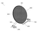
도 1은 본 발명에 따른 자체-구조 반사기를 갖는 파라볼라 안테나의 전 측방 사시도이다.
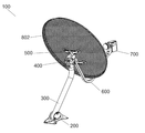
도 2는 본 발명에 따른 자체-구조 반사기가 있는 파라볼라 안테나의 후 외측 사시도이다.
도 3은 본 발명에 따른 자체-구조 반사기가 있는 파라볼라 안테나의 측면 사시도이다.
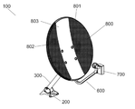
도 4는 본 발명에 따른 자체-구조 반사기가 있는 파라볼라 안테나의 형상 변형의 전 측방 사시도이다.
도 5는 본 발명에 따른 자체-구조 반사기가 있는 파라볼라 안테나의 형상 변형의 전 측방 사시도이다.
도 6은 본 발명에 따른 자체-구조 반사기가 있는 파라볼라 안테나의 형상 변형의 전 측방 사시도이다.
도 7은 본 발명에 따른 자체-구조 반사기가 있는 파라볼라 안테나의 형상 변형의 전 측방 사시도이다.
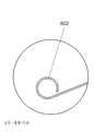
도 8은 롤링된 상태의 도 6의 "A"를 상세히 도시한다.
도 9는 하나 또는 두 개의 레벨로 "A"를 상세히 도시한다.
Claims (2)
- 베이스(200), 설치 폴(300), 헤드 유닛(400), 후방 구조(500), 지지 폴(600), 저소음 컨버터(700), 및 반사기(800)를 구비하는 자체-구조 반사기를 가진 파라볼라 안테나로서,
상기 반사기(800)는 적층된 확장 스크린(laminated expanded screen)에 단일체로 만들어지며, 파라볼라 형상이며, 어떤 베어링 프레임도 없는 자체-구조 형상이며, 고정 유닛(801)에 의해서 파라볼라 안테나(100)의 후방 구조(500)에 고정되며, 반사기(800)의 오목부로부터 먼 족으로 향하는 보강 에지(802)를 가지며,
보강 에지(802)는 반사기(800)의 주변 영역에서 하나 또는 두 개의 레벨로 굽혀지거나 또는 롤링되는 파라볼라 안테나. - 제 1 항에 있어서,
고정 유닛(801) 위로 연장되는 임의의 수직 및/또는 수평 배향으로, 하나 이상의 비-천공된 또는 매끄러운 구역들(803)을 포함하는 파라볼라 안테나.
Applications Claiming Priority (3)
| Application Number | Priority Date | Filing Date | Title |
|---|---|---|---|
| BR202014013528-1U BR202014013528Y1 (pt) | 2014-06-04 | 2014-06-04 | antena parabólica com refletor autoestruturado |
| BRBR2020140135281 | 2014-06-04 | ||
| PCT/BR2015/000082 WO2015184518A1 (pt) | 2014-06-04 | 2015-05-29 | Antena parabólica com refletor auto estruturado |
Publications (1)
| Publication Number | Publication Date |
|---|---|
| KR20170010373A true KR20170010373A (ko) | 2017-01-31 |
Family
ID=54765882
Family Applications (1)
| Application Number | Title | Priority Date | Filing Date |
|---|---|---|---|
| KR1020167033612A Ceased KR20170010373A (ko) | 2014-06-04 | 2015-05-29 | 자체-구조 반사기를 가진 파라볼라 안테나 |
Country Status (15)
| Country | Link |
|---|---|
| US (1) | US10038250B2 (ko) |
| EP (1) | EP3154129A4 (ko) |
| JP (1) | JP2017518009A (ko) |
| KR (1) | KR20170010373A (ko) |
| CN (1) | CN206962023U (ko) |
| AR (1) | AR104663A4 (ko) |
| BR (1) | BR202014013528Y1 (ko) |
| CA (1) | CA2947777C (ko) |
| CL (1) | CL2016002981U1 (ko) |
| EC (1) | ECSMU16090396U (ko) |
| MX (1) | MX2016015855A (ko) |
| PE (1) | PE20161518Z (ko) |
| RU (1) | RU175124U1 (ko) |
| UY (1) | UY4573U (ko) |
| WO (1) | WO2015184518A1 (ko) |
Cited By (1)
| Publication number | Priority date | Publication date | Assignee | Title |
|---|---|---|---|---|
| US11588232B2 (en) * | 2018-10-12 | 2023-02-21 | Commscope Technologies Llc | Flexible radome structures |
Family Cites Families (30)
| Publication number | Priority date | Publication date | Assignee | Title |
|---|---|---|---|---|
| US2471828A (en) | 1944-07-04 | 1949-05-31 | Skydyne Inc | Parabolic antenna |
| US2997712A (en) | 1957-06-14 | 1961-08-22 | Donald S Kennedy | Antenna reflector construction |
| US3150030A (en) * | 1960-04-06 | 1964-09-22 | Raytheon Co | Laminated plastic structure |
| US3234550A (en) | 1961-06-12 | 1966-02-08 | Washington Aluminum Company In | Thin skinned parabolic reflector with radial ribs |
| US3397399A (en) | 1966-02-07 | 1968-08-13 | Goodyear Aerospace Corp | Collapsible dish reflector |
| FR2117807B1 (ko) * | 1970-12-11 | 1973-12-28 | Girondon Michel | |
| US4378561A (en) | 1981-01-15 | 1983-03-29 | Hibbard Robert J | Parabolic reflector antenna |
| US4801946A (en) * | 1983-01-26 | 1989-01-31 | Mark Antenna Products, Inc. | Grid antenna |
| JPS59211303A (ja) * | 1983-05-16 | 1984-11-30 | Maspro Denkoh Corp | 高周波の通信信号用反射器 |
| JPS6045507U (ja) * | 1983-09-07 | 1985-03-30 | 住友電気工業株式会社 | パラボラアンテナ |
| JPS6057704A (ja) * | 1983-09-08 | 1985-04-03 | Sumitomo Electric Ind Ltd | オフセット型アンテナの楕円反射板製造方法 |
| US4578682A (en) | 1984-03-20 | 1986-03-25 | Raydx Satellite Systems, Ltd. | Antenna dish |
| US4568945A (en) | 1984-06-15 | 1986-02-04 | Winegard Company | Satellite dish antenna apparatus |
| EP0196607B1 (en) * | 1985-03-25 | 1991-04-24 | Kabushiki Kaisha Toshiba | A satellite broadcasting receiving system |
| US4647943A (en) | 1985-03-29 | 1987-03-03 | General Instrument Corporation | Mesh dish antenna and hub |
| US4916459A (en) * | 1986-03-19 | 1990-04-10 | Hitachi, Ltd. | Parabolic antenna dish |
| JP2750592B2 (ja) * | 1989-01-20 | 1998-05-13 | 株式会社柏原機械製作所 | パラボラアンテナ用金属デイッシュ縁端面のカール方法およびカール型 |
| JPH0496114U (ko) * | 1991-01-21 | 1992-08-20 | ||
| JPH05235630A (ja) * | 1992-02-18 | 1993-09-10 | Bridgestone Corp | パラボラアンテナ用のリフレクター |
| US5291212A (en) * | 1992-09-01 | 1994-03-01 | Andrew Corporation | Grid-type paraboloidal microwave antenna |
| JP3085512B2 (ja) * | 1993-12-24 | 2000-09-11 | 日本アンテナ株式会社 | パラボラアンテナ用ベースおよびパラボラアンテナ |
| US5421376A (en) * | 1994-01-21 | 1995-06-06 | Lockheed Missiles & Space Co., Inc. | Metallized mesh fabric panel construction for RF reflector |
| US5894290A (en) * | 1996-10-09 | 1999-04-13 | Espey Mfg. & Electronics Corp. | Parabolic rod antenna |
| US6188370B1 (en) * | 1999-06-24 | 2001-02-13 | California Amplifier, Inc. | Grid antennas and methods with efficient grid spacing |
| AU2001278672B2 (en) * | 2000-08-01 | 2004-07-15 | Tata Institute Of Fundamental Research | Preloaded parabolic dish antenna and the method of making it |
| WO2002018127A1 (en) * | 2000-08-28 | 2002-03-07 | Sakase Adtech Co., Ltd. | Composite material, formed product, and prepreg |
| JP2006074504A (ja) * | 2004-09-02 | 2006-03-16 | Mitsubishi Electric Corp | アンテナリフレクタおよびその製造方法 |
| TW200952261A (en) * | 2008-06-06 | 2009-12-16 | Azure Shine Int Inc | Manufacturing method of a satellite dish antenna that integrally displays trademark by visual contrast of hollw hole and the structure thereof |
| TW201112494A (en) * | 2009-09-25 | 2011-04-01 | Microelectronics Tech Inc | Assembly of clamping mechanism and LNB and disk antenna using the same |
| JP5693290B2 (ja) * | 2011-02-24 | 2015-04-01 | 三菱電機株式会社 | アンテナリフレクタの製造方法 |
-
2014
- 2014-06-04 BR BR202014013528-1U patent/BR202014013528Y1/pt active IP Right Grant
-
2015
- 2015-05-28 AR ARM150101683U patent/AR104663A4/es active IP Right Grant
- 2015-05-29 EP EP15802943.9A patent/EP3154129A4/en not_active Withdrawn
- 2015-05-29 KR KR1020167033612A patent/KR20170010373A/ko not_active Ceased
- 2015-05-29 RU RU2016148873U patent/RU175124U1/ru active
- 2015-05-29 PE PE2016002220U patent/PE20161518Z/es active IP Right Grant
- 2015-05-29 JP JP2017516009A patent/JP2017518009A/ja active Pending
- 2015-05-29 CN CN201590000662.7U patent/CN206962023U/zh not_active Expired - Fee Related
- 2015-05-29 CA CA2947777A patent/CA2947777C/en active Active
- 2015-05-29 MX MX2016015855A patent/MX2016015855A/es unknown
- 2015-05-29 WO PCT/BR2015/000082 patent/WO2015184518A1/pt not_active Ceased
- 2015-05-29 US US15/310,211 patent/US10038250B2/en active Active
- 2015-05-29 UY UY0001004573U patent/UY4573U/es active IP Right Grant
-
2016
- 2016-11-22 CL CL2016002981U patent/CL2016002981U1/es unknown
- 2016-11-28 EC ECIEPI201690396U patent/ECSMU16090396U/es unknown
Cited By (1)
| Publication number | Priority date | Publication date | Assignee | Title |
|---|---|---|---|---|
| US11588232B2 (en) * | 2018-10-12 | 2023-02-21 | Commscope Technologies Llc | Flexible radome structures |
Also Published As
| Publication number | Publication date |
|---|---|
| BR202014013528U2 (pt) | 2016-10-18 |
| ECSMU16090396U (es) | 2018-06-30 |
| JP2017518009A (ja) | 2017-06-29 |
| PE20161518Z (es) | 2017-01-15 |
| AR104663A4 (es) | 2017-08-09 |
| BR202014013528Y1 (pt) | 2018-11-06 |
| MX2016015855A (es) | 2017-06-06 |
| EP3154129A4 (en) | 2017-12-20 |
| EP3154129A1 (en) | 2017-04-12 |
| UY4573U (es) | 2016-01-08 |
| WO2015184518A8 (pt) | 2017-06-15 |
| CA2947777C (en) | 2021-06-08 |
| WO2015184518A1 (pt) | 2015-12-10 |
| US20170162946A1 (en) | 2017-06-08 |
| RU175124U1 (ru) | 2017-11-21 |
| CN206962023U (zh) | 2018-02-02 |
| CA2947777A1 (en) | 2015-12-10 |
| US10038250B2 (en) | 2018-07-31 |
| CL2016002981U1 (es) | 2017-07-14 |
Similar Documents
| Publication | Publication Date | Title |
|---|---|---|
| US20140230363A1 (en) | Dome cover supporter | |
| US10971794B2 (en) | Antenna mounting bracket assembly | |
| US20140063698A1 (en) | Back Frame and Liquid Display Device with the Same | |
| US20150214883A1 (en) | Support assembly for mounting a solar panel unit | |
| CN100416920C (zh) | 预载抛物柱面反射器天线及其制造方法 | |
| US20200123790A1 (en) | High capacity platforms and cage mount assemblies | |
| KR20170010373A (ko) | 자체-구조 반사기를 가진 파라볼라 안테나 | |
| CN104991998B (zh) | 一种具有高抗风性能的架空输电杆塔 | |
| CN107112619A (zh) | 针对现有天线杆安装座的滤波器支架安装座 | |
| CN110596991A (zh) | 一种适用于同轴式微纳遥感相机的超轻型消杂光组件 | |
| CN104241805A (zh) | 一种反射索网以及具有该反射索网的伞状天线反射器 | |
| CN210670933U (zh) | 框架结构及led显示屏 | |
| US4405928A (en) | Wind load reduction in tower mounted broadcast antennas | |
| CN204834868U (zh) | 一种l频段测向天线 | |
| CN207705386U (zh) | 一种天线罩 | |
| US20200392726A1 (en) | Sandwich panel | |
| CN222769591U (zh) | 一种航测无人机辅助架 | |
| CN218640452U (zh) | 一种蜂窝板结构 | |
| US20180212332A1 (en) | Non-rms affecting mounting system for antenna systems | |
| JP2018016286A (ja) | ソーラパネル用の樹脂製のフロート及びそのフロートの製造方法 | |
| CN201490346U (zh) | 全频道接收天线 | |
| CN213390551U (zh) | 一种玻璃钢天幕 | |
| AU2006100495A4 (en) | Antenna unit | |
| CN205338104U (zh) | 钢板高低四爪 | |
| CN107224806A (zh) | 一种骨架和滤网一体化的过滤片 |
Legal Events
| Date | Code | Title | Description |
|---|---|---|---|
| PA0105 | International application |
Patent event date: 20161130 Patent event code: PA01051R01D Comment text: International Patent Application |
|
| PG1501 | Laying open of application | ||
| A201 | Request for examination | ||
| PA0201 | Request for examination |
Patent event code: PA02012R01D Patent event date: 20200527 Comment text: Request for Examination of Application |
|
| E902 | Notification of reason for refusal | ||
| PE0902 | Notice of grounds for rejection |
Comment text: Notification of reason for refusal Patent event date: 20210422 Patent event code: PE09021S01D |
|
| E601 | Decision to refuse application | ||
| PE0601 | Decision on rejection of patent |
Patent event date: 20210725 Comment text: Decision to Refuse Application Patent event code: PE06012S01D Patent event date: 20210422 Comment text: Notification of reason for refusal Patent event code: PE06011S01I |