KR20170077192A - Method for producing a component by subjecting a sheet bar of steel to a forming process - Google Patents
Method for producing a component by subjecting a sheet bar of steel to a forming process Download PDFInfo
- Publication number
- KR20170077192A KR20170077192A KR1020177014382A KR20177014382A KR20170077192A KR 20170077192 A KR20170077192 A KR 20170077192A KR 1020177014382 A KR1020177014382 A KR 1020177014382A KR 20177014382 A KR20177014382 A KR 20177014382A KR 20170077192 A KR20170077192 A KR 20170077192A
- Authority
- KR
- South Korea
- Prior art keywords
- manufacturing
- component
- plate
- temperature
- edge
- Prior art date
- Legal status (The legal status is an assumption and is not a legal conclusion. Google has not performed a legal analysis and makes no representation as to the accuracy of the status listed.)
- Granted
Links
Images


Classifications
-
- B—PERFORMING OPERATIONS; TRANSPORTING
- B21—MECHANICAL METAL-WORKING WITHOUT ESSENTIALLY REMOVING MATERIAL; PUNCHING METAL
- B21D—WORKING OR PROCESSING OF SHEET METAL OR METAL TUBES, RODS OR PROFILES WITHOUT ESSENTIALLY REMOVING MATERIAL; PUNCHING METAL
- B21D35/00—Combined processes according to or processes combined with methods covered by groups B21D1/00 - B21D31/00
-
- C—CHEMISTRY; METALLURGY
- C21—METALLURGY OF IRON
- C21D—MODIFYING THE PHYSICAL STRUCTURE OF FERROUS METALS; GENERAL DEVICES FOR HEAT TREATMENT OF FERROUS OR NON-FERROUS METALS OR ALLOYS; MAKING METAL MALLEABLE, e.g. BY DECARBURISATION OR TEMPERING
- C21D8/00—Modifying the physical properties of ferrous metals or ferrous alloys by deformation combined with, or followed by, heat treatment
-
- B—PERFORMING OPERATIONS; TRANSPORTING
- B21—MECHANICAL METAL-WORKING WITHOUT ESSENTIALLY REMOVING MATERIAL; PUNCHING METAL
- B21D—WORKING OR PROCESSING OF SHEET METAL OR METAL TUBES, RODS OR PROFILES WITHOUT ESSENTIALLY REMOVING MATERIAL; PUNCHING METAL
- B21D22/00—Shaping without cutting, by stamping, spinning, or deep-drawing
- B21D22/02—Stamping using rigid devices or tools
- B21D22/022—Stamping using rigid devices or tools by heating the blank or stamping associated with heat treatment
-
- B—PERFORMING OPERATIONS; TRANSPORTING
- B21—MECHANICAL METAL-WORKING WITHOUT ESSENTIALLY REMOVING MATERIAL; PUNCHING METAL
- B21D—WORKING OR PROCESSING OF SHEET METAL OR METAL TUBES, RODS OR PROFILES WITHOUT ESSENTIALLY REMOVING MATERIAL; PUNCHING METAL
- B21D22/00—Shaping without cutting, by stamping, spinning, or deep-drawing
- B21D22/02—Stamping using rigid devices or tools
- B21D22/04—Stamping using rigid devices or tools for dimpling
-
- B—PERFORMING OPERATIONS; TRANSPORTING
- B21—MECHANICAL METAL-WORKING WITHOUT ESSENTIALLY REMOVING MATERIAL; PUNCHING METAL
- B21D—WORKING OR PROCESSING OF SHEET METAL OR METAL TUBES, RODS OR PROFILES WITHOUT ESSENTIALLY REMOVING MATERIAL; PUNCHING METAL
- B21D28/00—Shaping by press-cutting; Perforating
- B21D28/02—Punching blanks or articles with or without obtaining scrap; Notching
-
- B—PERFORMING OPERATIONS; TRANSPORTING
- B21—MECHANICAL METAL-WORKING WITHOUT ESSENTIALLY REMOVING MATERIAL; PUNCHING METAL
- B21D—WORKING OR PROCESSING OF SHEET METAL OR METAL TUBES, RODS OR PROFILES WITHOUT ESSENTIALLY REMOVING MATERIAL; PUNCHING METAL
- B21D35/00—Combined processes according to or processes combined with methods covered by groups B21D1/00 - B21D31/00
- B21D35/001—Shaping combined with punching, e.g. stamping and perforating
-
- B—PERFORMING OPERATIONS; TRANSPORTING
- B21—MECHANICAL METAL-WORKING WITHOUT ESSENTIALLY REMOVING MATERIAL; PUNCHING METAL
- B21D—WORKING OR PROCESSING OF SHEET METAL OR METAL TUBES, RODS OR PROFILES WITHOUT ESSENTIALLY REMOVING MATERIAL; PUNCHING METAL
- B21D53/00—Making other particular articles
- B21D53/88—Making other particular articles other parts for vehicles, e.g. cowlings, mudguards
-
- C—CHEMISTRY; METALLURGY
- C21—METALLURGY OF IRON
- C21D—MODIFYING THE PHYSICAL STRUCTURE OF FERROUS METALS; GENERAL DEVICES FOR HEAT TREATMENT OF FERROUS OR NON-FERROUS METALS OR ALLOYS; MAKING METAL MALLEABLE, e.g. BY DECARBURISATION OR TEMPERING
- C21D1/00—General methods or devices for heat treatment, e.g. annealing, hardening, quenching or tempering
- C21D1/02—Hardening articles or materials formed by forging or rolling, with no further heating beyond that required for the formation
-
- C—CHEMISTRY; METALLURGY
- C21—METALLURGY OF IRON
- C21D—MODIFYING THE PHYSICAL STRUCTURE OF FERROUS METALS; GENERAL DEVICES FOR HEAT TREATMENT OF FERROUS OR NON-FERROUS METALS OR ALLOYS; MAKING METAL MALLEABLE, e.g. BY DECARBURISATION OR TEMPERING
- C21D1/00—General methods or devices for heat treatment, e.g. annealing, hardening, quenching or tempering
- C21D1/26—Methods of annealing
-
- C—CHEMISTRY; METALLURGY
- C21—METALLURGY OF IRON
- C21D—MODIFYING THE PHYSICAL STRUCTURE OF FERROUS METALS; GENERAL DEVICES FOR HEAT TREATMENT OF FERROUS OR NON-FERROUS METALS OR ALLOYS; MAKING METAL MALLEABLE, e.g. BY DECARBURISATION OR TEMPERING
- C21D7/00—Modifying the physical properties of iron or steel by deformation
- C21D7/02—Modifying the physical properties of iron or steel by deformation by cold working
-
- C21D8/005—
-
- C—CHEMISTRY; METALLURGY
- C21—METALLURGY OF IRON
- C21D—MODIFYING THE PHYSICAL STRUCTURE OF FERROUS METALS; GENERAL DEVICES FOR HEAT TREATMENT OF FERROUS OR NON-FERROUS METALS OR ALLOYS; MAKING METAL MALLEABLE, e.g. BY DECARBURISATION OR TEMPERING
- C21D8/00—Modifying the physical properties of ferrous metals or ferrous alloys by deformation combined with, or followed by, heat treatment
- C21D8/02—Modifying the physical properties of ferrous metals or ferrous alloys by deformation combined with, or followed by, heat treatment during manufacturing of plates or strips
-
- C—CHEMISTRY; METALLURGY
- C21—METALLURGY OF IRON
- C21D—MODIFYING THE PHYSICAL STRUCTURE OF FERROUS METALS; GENERAL DEVICES FOR HEAT TREATMENT OF FERROUS OR NON-FERROUS METALS OR ALLOYS; MAKING METAL MALLEABLE, e.g. BY DECARBURISATION OR TEMPERING
- C21D9/00—Heat treatment, e.g. annealing, hardening, quenching or tempering, adapted for particular articles; Furnaces therefor
- C21D9/46—Heat treatment, e.g. annealing, hardening, quenching or tempering, adapted for particular articles; Furnaces therefor for sheet metals
- C21D9/48—Heat treatment, e.g. annealing, hardening, quenching or tempering, adapted for particular articles; Furnaces therefor for sheet metals deep-drawing sheets
-
- C—CHEMISTRY; METALLURGY
- C21—METALLURGY OF IRON
- C21D—MODIFYING THE PHYSICAL STRUCTURE OF FERROUS METALS; GENERAL DEVICES FOR HEAT TREATMENT OF FERROUS OR NON-FERROUS METALS OR ALLOYS; MAKING METAL MALLEABLE, e.g. BY DECARBURISATION OR TEMPERING
- C21D2211/00—Microstructure comprising significant phases
- C21D2211/002—Bainite
-
- C—CHEMISTRY; METALLURGY
- C21—METALLURGY OF IRON
- C21D—MODIFYING THE PHYSICAL STRUCTURE OF FERROUS METALS; GENERAL DEVICES FOR HEAT TREATMENT OF FERROUS OR NON-FERROUS METALS OR ALLOYS; MAKING METAL MALLEABLE, e.g. BY DECARBURISATION OR TEMPERING
- C21D2211/00—Microstructure comprising significant phases
- C21D2211/008—Martensite
-
- C—CHEMISTRY; METALLURGY
- C21—METALLURGY OF IRON
- C21D—MODIFYING THE PHYSICAL STRUCTURE OF FERROUS METALS; GENERAL DEVICES FOR HEAT TREATMENT OF FERROUS OR NON-FERROUS METALS OR ALLOYS; MAKING METAL MALLEABLE, e.g. BY DECARBURISATION OR TEMPERING
- C21D2221/00—Treating localised areas of an article
- C21D2221/02—Edge parts
-
- C—CHEMISTRY; METALLURGY
- C21—METALLURGY OF IRON
- C21D—MODIFYING THE PHYSICAL STRUCTURE OF FERROUS METALS; GENERAL DEVICES FOR HEAT TREATMENT OF FERROUS OR NON-FERROUS METALS OR ALLOYS; MAKING METAL MALLEABLE, e.g. BY DECARBURISATION OR TEMPERING
- C21D2261/00—Machining or cutting being involved
Landscapes
- Engineering & Computer Science (AREA)
- Chemical & Material Sciences (AREA)
- Mechanical Engineering (AREA)
- Physics & Mathematics (AREA)
- Thermal Sciences (AREA)
- Materials Engineering (AREA)
- Crystallography & Structural Chemistry (AREA)
- Metallurgy (AREA)
- Organic Chemistry (AREA)
- Shaping Metal By Deep-Drawing, Or The Like (AREA)
- Heat Treatment Of Articles (AREA)
- Laser Beam Processing (AREA)
- Metal Rolling (AREA)
Abstract
본 발명은 특허 청구항 1의 전제부에 따라 강 시트 바에 성형 공정을 가함으로써 부품을 제조하는 방법에 관한 것으로서, 이는 냉간 경화된 기계적으로 분리된 시트의 에지에 성형을 가할 수 있게 하고, 부품으로의 성형과 무관하게, 시트 바를 적절한 크기로 절단한 후 및 임의의 추가의 스탬핑 또는 절단 작업 후의 임의의 원하는 시점에서 절단 또는 펀칭 작업에 의해 냉간 경화된, 그리고 부품의 제조 시 후속 냉간 가공되는 시트의 에지는 600℃ 이상의 온도까지 가열되고, 온도 노출 시간은 10초 이하이다.The present invention relates to a method of manufacturing a component by applying a forming process to a steel sheet bar according to the preamble of claim 1, which enables molding to be applied to the edge of the cold-hardened, mechanically separated sheet, The edge of the sheet being cold-cured by cutting or punching operation at any desired point after cutting the sheet bar to an appropriate size and after any additional stamping or cutting operation, Is heated to a temperature of 600 DEG C or higher, and the temperature exposure time is 10 seconds or less.
Description
본 발명은 변형 경화되고, 기계적으로 분리된 플레이트 에지의 높은 성형성을 가능하게 하는, 특허 청구항 1의 전제부에 따라 강 플레이트를 성형함으로써 부품을 제조하는 방법에 관한 것이다.The present invention relates to a method of manufacturing a component by molding a steel plate in accordance with the preamble of
이하에서, 부품이라는 용어는 실온에서 성형 공구로 성형하여 금속 플레이트로 제조된 부품을 의미한다. 사용될 수 있는 금속 재료는 모든 성형가능한 금속 재료, 그러나 특히 강을 포함한다. 금속 플레이트는 코팅되지 않거나, 또는 금속 코팅 및/또는 유기 부식 방지 코팅을 구비할 수 있다.Hereinafter, the term " part " refers to a part made of a metal plate molded into a molding tool at room temperature. Metal materials that can be used include all moldable metal materials, but especially steel. The metal plate may be uncoated, or may have a metal coating and / or an organic corrosion resistant coating.
이러한 부품은 주로 차체 구조에서 사용되지만, 또한 가정용 전기제품 산업, 기계 구조 또는 건축 산업에서도 사용된다.These components are mainly used in the car body structure, but also in the household electric appliance industry, mechanical structure or construction industry.
치열하게 경쟁하는 자동차 시장으로 인해 제조업체들은 최고의 가능한 편의 및 승객 보호를 유지하면서 신속한 소비를 저감시키기 위한 해결책을 끊임없이 모색해야 한다. 이로 인해 한편으로 모든 차량 부품의 중량을 절감하는 것은 중요한 역할을 하지만, 작동 중에 그리고 충돌 시에 높은 정적 응력 및 동적 응력 중에 부품의 최적 거동을 보장한다.Because of the highly competitive automotive market, manufacturers must constantly seek solutions to reduce their rapid consumption while maintaining the highest possible convenience and passenger protection. This, on the one hand, plays an important role in reducing the weight of all vehicle components, but ensures optimal behavior of the part during high static and dynamic stresses during operation and during impact.
원재료 공급업체는 제조 및 작동 중에 개선된 부품 특성을 제공함과 동시에 벽 두께의 감소를 가능하게 하는 고강도 및 초고강도의 강을 제공함으로써 재료에 대한 요구를 해결하고자 노력하고 있다.Raw material suppliers strive to address the need for materials by providing high strength and ultra high strength steels that enable reduced wall thickness while providing improved component properties during manufacturing and operation.
따라서, 이러한 강은 강도, 전성, 강인성, 에너지 흡수, 내식성, 및 예를 들면 냉간 성형 및 용접 중의 처리가능성에 관한 비교적 높은 요구사항을 충족시켜야 한다.Therefore, such steels must meet the relatively high requirements of strength, toughness, toughness, energy absorption, corrosion resistance, and the likelihood of processing during cold forming and welding, for example.
전술한 양태 중에서, 600 MPa를 초과하는 항복 강도를 갖는 더 고강도 강 및 고강도 강으로 된 부품의 제조는 점점 더 중요해지고 있다.Among the embodiments described above, the manufacture of parts made of higher strength and higher strength steels with a yield strength exceeding 600 MPa is becoming increasingly important.
부품을 제조하기 위해, 먼저 금속 플레이트가 실온에서 핫 스트립이나 콜드 스트립으로부터 적절한 크기로 절단된다. 이 목적을 위해 사용되는 절단 방법은 전단 또는 펀칭과 같은 기계적 분리 공정을 주로 포함하고, 또한 레이저 절단과 같은 열적 분리 공정도 적은 빈도로 포함한다. 열적 분리 방법은 기계적 분리 방법에 비해 상당히 비싸므로 예외적인 경우에만 사용된다.To make the part, the metal plate is first cut to a suitable size from hot strip or cold strip at room temperature. The cutting methods used for this purpose mainly include mechanical separation processes such as shearing or punching, and also include thermal separation processes such as laser cutting with less frequency. The thermal separation method is extremely expensive compared to the mechanical separation method and is therefore used only in exceptional cases.
적절한 크기로 절단된 후에 이 절단된 플레이트는 성형 공구 내에 배치되고, 예를 들면, 차량 섀시와 같은 완성된 부품은 단일 단계 또는 다중 단계의 성형 공정으로 제조된다.After being cut to the appropriate size, the cut plate is placed in a forming tool, and finished parts such as, for example, a vehicle chassis are manufactured in a single step or multi-step molding process.
성형 전에, 예를 들면, 펀칭 및 절단 작업과 같은 다양한 선택적인 추가의 제조 단계가 플레이트 상에 수행되고, 성형 중에 결합된 플랜징(flanging) 작업이 펀칭된 섹션에서 수행된다.Before molding, various optional additional manufacturing steps such as, for example, punching and cutting operations are performed on the plate, and a flanging operation coupled during molding is performed in the punched section.
성형 중에, 특히 예를 들면, 펀칭된 플레이트에서의 플랜징 작업 중에 상방으로의 굴곡 시에, 절단된 에지에는 특히 높은 응력이 가해진다.Particularly high stresses are applied to the cut edges during molding, for example when bent upwardly during flanging work on punched plates.
절단된 에지에는 사전 손상이 존재할 수 있다. 이것은 한편으로 재료가 분리될 때까지의 총 변형을 나타내는 기계적 분리에 의해 유발된 재료의 변형 경화에 기인될 수 있다. 다른 한편 절단된 표면의 토포그래피(topography)에 의해 유발될 수 있는 노치 효과가 발생할 수 있다.Pre-damage may be present at the severed edge. This may be due to the strain hardening of the material caused by mechanical separation, which on the one hand represents the total deformation until the material is separated. On the other hand, a notch effect that can be caused by the topography of the cut surface can occur.
따라서, 특히 고강도 및 초고강도 시트 금속 재료의 경우, 후속 성형 중에 이들 절단된 에지의 경계 영역에서 균열이 형성될 가능성이 증가된다.Thus, especially for high strength and ultra high strength sheet metal materials, the likelihood of crack formation in the boundary regions of these cut edges during subsequent molding is increased.
플레이트 에지에서의 전술한 사전 손상은 후속 성형 작업이나 부품의 작동 중에 조기 파괴를 초래할 수 있다. 에지 균열 형성에 대한 민감도와 관련하여 절단된 플레이트 에지의 성형 특성의 시험은 ISO 16630에 따른 홀(hole) 팽창 시험으로 수행된다.The above-mentioned prior damage at the plate edge can lead to premature failure during subsequent molding operations or part operation. Testing of the forming properties of the cut edge of the plate in relation to the sensitivity to edge cracking is carried out with a hole expansion test according to ISO 16630.
홀 팽창 시험 시에 원형 홀이 전단 절단에 의해 금속 내에 도입되고, 다음에 이 홀은 원추형 다이에 의해 확장된다. 측정 변수는 시작 직경에 대한 홀 직경(홀의 경계에서 첫번째 균열이 발생하는 홀 직경)의 변화이다.During the hole expansion test, the circular hole is introduced into the metal by shearing, which is then expanded by a conical die. The measured variable is the change in the hole diameter to the starting diameter (the hole diameter at which the first crack occurs at the boundary of the hole).
전단 절단되거나 펀칭된 플레이트 에지의 냉간 성형 중에 전술한 에지 균열 민감도를 최소화하기 위한 공지된 접근법은 합금 조성을 변화시키고, 재료를 처리하는 것(예를 들면, 베이나이트계 미세구조의 표적화된 조절) 또는 (예를 들면, 절단 간극, 속도, 다중 절단 등의 변경을 통해) 플레이트의 냉간 절단 중에 공정 기술을 변화시키는 것을 포함한다. A known approach for minimizing the edge cracking sensitivity described above during cold forming of sheared or punched plate edges is to change the alloy composition and to treat the material (e.g., targeted control of the bainitic microstructure) or (E. G., Through alteration of cut clearance, speed, multiple cut, etc.) during cold cutting of the plate.
이러한 조치는 고비용이고 불편(예를 들면, 다단계 절단 작업, 3D 절단 유지관리 등)하고, 또는 최적의 결과를 제공하지 못한다.Such measures are costly and inconvenient (e.g., multi-stage cutting operations, 3D cutting maintenance, etc.), or fail to provide optimal results.
또한 공개 문헌 DE 10 2009 049 155 A1으로부터 적어도 절단된 에지의 영역을 규정된 온도까지 가열하고, 절단된 에지의 성형성을 개선하기 위해 이 온도에서 절단을 수행함으로써 이 절단된 에지의 영역에서 변형 경화를 감소시키거나 또는 방지하는 것이 공지되어 있다. 단점은 금속을 가열하기 위한 고도의 기술적 비용 및 경제적 비용 및 플레이트의 가열 및 절단 직후의 강제 커플링으로서, 이로 인해 생산의 유연성이 감소된다.It is also known from published
DE 10 2011 212 904로부터 전단 절단된 플레이트를 냉간 성형하고, 부분 연화를 목표로 하여 레이저로 변형 경화 영역을 국부적으로 가열하는 것이 공지되어 있다. 여기서의 단점은 특히 하중 조건 및 진동 응력의 경우에 빈번하게 사용되는 고강도 및 초고강도 재료에 대한 단점인 국부 연화(local softening)이다. 또한, 가열이 발생하는 정확한 위치, 또는 국소 가열의 구체적 온도 및 시간적 경과가 명확하지 않다. 부분적 연화가 어떻게 그리고 어느 정도까지 이미 냉간 성형된 플레이트의 성형 능력을 개선할 수 있는지도 명확하지 않다.It is known to cold-mold a plate cut from a shearing cut from
본 발명의 목적은, 예를 들면, 홀 펀칭 또는 절단 작업과 같은 실온에서 수행되는 잠재적인 추가의 제조 단계로 실온에서 전단 절단된 금속 플레이트로부터 냉간 성형된 부품을 제조하기 위한 방법을 개시하는 것이며, 이 방법은 절단 영역의 사전 손상의 효과를 감소 또는 제거하고, 따라서 금속 플레이트의 후속 냉간 성형에서 엔지 균열 민감도를 감소시키거나 심지어 제거한다. 본 방법은 간단하고, 비용 효율적이며, 한편으로는 생산성에 관하여, 특히 절단된 에지의 성형성에 관하여, 다른 한편으로는 부품에서, 특히 정적 강도에 관하여, 동등하거나 및/또는 향상된 특성을 달성한다.It is an object of the present invention to disclose a method for manufacturing a cold-formed part from a metal plate sheared at room temperature into a potential further manufacturing step, for example, performed at room temperature, such as a hole punching or cutting operation, This method reduces or eliminates the effect of pre-cracking of the cut area, thus reducing or even eliminating engine crack susceptibility in subsequent cold forming of the metal plate. The method is simple, cost effective and on the one hand achieves equivalent and / or improved properties with respect to productivity, particularly with respect to the formability of the cut edges, on the one hand, in particular on static strength.
본 발명의 교시에 따르면, 이 목적은 기계적으로 절단되거나 펀칭된, 그리고 높은 성형성 및 감소된 균열 민감도의 에지를 갖는 플레이트를 실온에서 강으로부터 성형함으로써 부품을 제조하는 방법에 의해 달성되고, 이 방법에서 플레이트는 사전에 실온에서 스트립 또는 플레이트로부터 적절한 크기로 절단되고, 여기서 당면한 상황에 따라 추가의 제조 단계, 예를 들면, 시트 금속 또는 플레이트 상에 리세스 또는 천공을 생성하기 위한 펀칭 또는 절단 작업이 실온에서 수행되고, 후속하여 이렇게 제조된 플레이트가 실온에서 일단계 또는 다단계로 부품으로 성형되고, 본 방법은 부품으로의 성형에 무관하게, 그리고 적절한 크기로 절단 후 및 가능한 추가의 펀칭 또는 절단 작업 후의 임의의 시점에서, 절단 또는 펀칭 작업에 의해 변형 경화된, 그리고 부품의 제조 중에 후속 냉간 성형을 받는 금속 플레이트의 에지 영역이 600℃의 온도까지 가열되고, 열처리의 시간은 10 초 미만인 것을 특징으로 한다.According to the teachings of the present invention, this object is achieved by a method of manufacturing a part by mechanically cutting or punching a plate from a steel at room temperature, the plate having edges of high moldability and reduced crack sensitivity, The plate is cut in advance to a suitable size from the strip or plate at room temperature, where punching or cutting operations to produce a recess or perforation on the sheet metal or plate, depending on the situation in question, The plate thus produced is subsequently molded at one or more stages in a single step at room temperature, and the method is carried out at a temperature of about < RTI ID = 0.0 > At any point in time, it may be subjected to a strain hardening by cutting or punching operation, The edge of the metal plate subjected to subsequent cold forming, and heated to a temperature of 600 ℃ during manufacture of the components, the time of the heat treatment is characterized in that less than 10 seconds.
시험은 홀 팽창 능력을 향상시키기 위해 절단 공정 자체를 절단된 에지 영역의 증가된 온도에서 수행할 필요가 없고, 10 초 미만, 통상적으로는 0.1 내지 2 초의 매우 짧은 시간 동안 600℃ 이상의 온도로 전단-충격에 의해 절단된 에지 영역을 가열하는 것만으로 충분하다는 것을 보여주었다. 본 발명에 따르면, 이는 부품으로 성형되기 전의 임의의 시점에서 절단 또는 펀칭 공정 및 후속되는 제조 단계와 무관하게 수행될 수 있다.The test does not require the cutting process itself to be performed at an increased temperature of the cut edge region to improve the hole expanding ability and does not require a shear- It has been shown that it is sufficient to heat the edge region cut by impact. According to the present invention, this can be done at any time before molding into the part, regardless of the cutting or punching process and subsequent manufacturing steps.
그 결과 열 영향은 시트 두께의 전체에 걸쳐, 그리고 일 영역 내의 플레이트의 평면 방향으로 작용하고, 이것은 최대로 시트 두께에 대응한다. 열 영향의 지속시간은 열처리 방법의 유형에 의존된다.As a result, the thermal effect acts on the entire sheet thickness and in the plane direction of the plate in one region, which corresponds to a maximum sheet thickness. The duration of the thermal effect depends on the type of heat treatment method.
가열 자체는 임의의 방법으로, 예를 들면, 복사 가열을 통한 전도 가열 및 유도 가열, 또는 레이저 처리에 의해 수행될 수 있다. 열처리를 위해 매우 적합한 것은, 예를 들면, 자동차 제조에서, 예를 들면, 스폿 용접에서 사용되는 전도 가열이다. 유리하게는, 예를 들면, 비교적 짧은 충격 시간을 갖는 스폿 용접 기계는 플레이트에 펀칭된 홀에 대해 적합하지만, 더 긴 에지 섹션을 처리하기 위해서는 더 긴 충격 시간을 갖는 유도적 방법, 복사 가열 또는 레이저 처리가 유용하다.The heating itself may be carried out in any way, for example, by conduction heating through radiation heating and induction heating, or by laser treatment. Very suitable for heat treatment is, for example, conduction heating used in automobile manufacturing, for example in spot welding. Advantageously, for example, a spot welding machine with a relatively short impact time is suitable for holes punched into the plate, but an inductive method with a longer impact time to process longer edge sections, Processing is useful.
가열된 절단된 에지 영역을 산화로부터 보호하기 위해, 본 발명의 유리한 실시형태는 이들 영역을 불활성 기체, 예를 들면, 아르곤으로 세척한다. 여기서 불활성 기체로의 세척은 열처리의 지속시간 중에 수행되지만 필요한 경우에는 열처리의 개시 전에 미리 및/또는 열처리 후의 제한된 시간 내에 추가로 수행될 수 있다.To protect the heated cut edge area from oxidation, an advantageous embodiment of the invention cleans these areas with an inert gas, such as argon. Here, the cleaning with an inert gas is carried out during the duration of the heat treatment, but if necessary, it can be carried out beforehand before the start of the heat treatment and / or within a limited time after the heat treatment.
따라서, 열처리는 전단 충격을 받은 절단된 에지 영역에서 매우 집중적으로 수행되고, 따라서 특히 전체 금속 플레이트가 가열되거나 여러 자릿수 만큼 더욱 시간 집약적인 응력 제거 어닐링이 사용되는 방법에 비해 비교적 작은 에너지 투자와 관련된다.Thus, the heat treatment is carried out very intensively in the sheared edge region subjected to shear impact, and thus is associated with a relatively small energy investment, in particular when compared to a method in which the entire metal plate is heated or stress-relieved annealing several orders of magnitude more time- .
또한, 절단된 에지 영역에서 도달되는 온도의 관리한계가 매우 넓고, 600℃를 초과하여 최대 약 1500℃의 고상선 온도에 이르는 온도 범위를 포함한다.Also, the management limit of the temperature reached in the cut edge region is very wide and includes a temperature range of up to about 1500 占 폚 to a solidus temperature of more than 600 占 폚.
시험은 또한 변형 경화의 제거만이 홀 팽창 능력의 상당한 향상을 위해 중요하고, 예를 들면, 기공과 같은 경화불가능한 결함은 덜 중요한 것임을 보여주었다.Testing has also shown that only the removal of strain hardening is important for a significant improvement in hole expandability and that non-hardenable defects such as, for example, pores are less important.
이는 열처리가 변태 온도(Ac1) 미만에서 또는 이것을 초과하여 수행되는지의 여부에는 무관하다.This is irrelevant whether the heat treatment is carried out at or below the transformation temperature Ac1.
Ac1을 초과하여 열처리가 수행되는 경우, 소위 준안정상으로의 변태가 주위의 차가운 재료에 기인되는 신속한 냉각 중의 처리 후에 변태 가능한 강에서 발생된다. 그 위에 형성된 미세구조는 출발 상태에 비해 증가된 강도를 갖는다.When a heat treatment is performed in excess of Ac1, a so-called quasi-normal transformation is generated in the transformable steel after the treatment during rapid cooling caused by the surrounding cool material. The microstructure formed thereon has an increased strength compared to the starting state.
놀랍게도, 통상적으로 관련되는 경도 및 강도 증가를 갖는 미세구조 변태는 경도가 낮은 또는 강인성이 낮은 미세구조가 형성되는지의 여부에 무관하게 통상적으로 홀 팽창 능력에 악영향을 미치지 않으므로 절단된 에지의 처리 온도는 고상선 온도 한계까지 가능하다. 중요한 요인은 어느 경우에도 절단에 의해 도입된 변형 경화가 최대의 정도까지 제거되는 것이다.Surprisingly, the microstructure transformation with the usually associated hardness and strength enhancement does not normally adversely affect the hole expandability, regardless of whether a low-hardness or low-toughness microstructure is formed, so the processing temperature of the cut edge is It is possible to reach the solidus temperature limit. An important factor is that in any case the strain hardening introduced by cutting is removed to a maximum extent.
본 발명에 따른 목적을 달성하기 위해, 본 시험에 따르면 기계적 분리 공정에 의해 도입된 전위(dislocation)의 현저한 감소가 발생되어야 하므로 600℃ 미만으로 수 초의 지속시간 동안 가열하는 것으로는 충분하지 않다.In order to achieve the object according to the invention, it is not sufficient according to this test to heat for a duration of a few seconds to less than 600 ° C, since a significant reduction in the dislocation introduced by the mechanical separation process has to occur.
에지 균열 민감도를 낮추기 위한 공지된 방법에 비해, 본 발명에 따른 방법은 열처리의 결과로서 전단-충격을 받은 에지 영역만이 미세구조 변화를 겪게 되므로 강도가 감소되지 않고 증가된다는 장점을 갖는다. 따라서, 더 큰 홀 팽창 능력에 의해 증명되는 에지 균열에 대한 저항은 2 배 또는 심지어 3 배를 초과하는 만큼 향상될 수 있다.Compared to the known method for lowering the edge cracking sensitivity, the method according to the present invention has the advantage that only the shear-impacted edge region as a result of the heat treatment undergoes the microstructure change, so that the strength is not increased but increased. Thus, the resistance to edge cracks evidenced by the larger hole expandability can be improved by as much as two or even three times.
본 발명에 따른 방법의 산업적 적용에서, 성형된 부품의 스크랩은 임계적으로 전단-충격을 받은 플레이트 에지 영역의 상당히 증가된 성형성으로 인해 저감될 수 있고, 다른 한편 예를 들면, 베어링 부위의 형성 중에 플랜징(flanging) 작업이 수행될 수 있으므로 현재 요구되는 접합 작업은 생?U될 수 있다.In the industrial application of the method according to the invention, the scrap of the molded part can be reduced due to the significantly increased formability of the plate edge area which is critically shear-impacted, and on the other hand the formation of the bearing part The flanging operation can be performed, and therefore, the currently required bonding operation can be performed.
따라서, 본 발명에 따른 방법은 절단된 에지 영역의 개선된 성형 능력의 결과로서 더 복잡한 부품 형상 및 이에 따라 동일한 재료를 이용한 더 큰 구조적 자유도를 가능하게 한다. 또한, 예를 들면, 이중상 미세구조와 같은 현저한 이중상 미세구조에서 예상되는 바와 같이, 생성된 미세구조가 보다 균질한 출발 상태에 비해 더 높은 경도를 가질 수 있으므로 냉간 성형 부품의 피로 강도는 감소되지 않고 증가된다.Thus, the method according to the present invention allows for a more complicated part shape as a result of the improved forming ability of the cut edge area and thus greater structural freedom with the same material. Also, as predicted for example in a pronounced dual phase microstructure, such as a dual phase microstructure, the resulting microstructure can have a higher hardness relative to a more homogeneous starting state, so that the fatigue strength of the cold formed part is not reduced .
냉간 성형될 절단된 에지 영역의 열처리는 절단 또는 펀칭 공정 후 및 플레이트의 성형 전의 임의의 시점에서 완전히 수행될 수 있거나, 플레이트가 부품으로 서형되는 다단계 성형 작업의 중간 단계로서 수행될 수 있으므로, 플레이트를 절단 또는 펀칭하는 공정 단계, 절단된 에지의 열처리, 및 플레이트를 부품으로 성형하는 단계는 서로 완전히 분리될 수 있다. 따라서, 본 제조는 열처리에 의한 에지의 개질을 포함하는 종래 기술에 따라 가능한 것보다 훨씬 더 유연하다.The heat treatment of the cut edge region to be cold-formed can be performed completely after the cutting or punching process and at any time before molding of the plate, or can be performed as an intermediate step of a multi-step molding operation in which the plate is printed with parts, The steps of cutting or punching, heat treating the cut edges, and shaping the plate into parts can be completely separated from each other. Thus, the present manufacturing is much more flexible than is possible according to the prior art, including the modification of the edge by heat treatment.
공지된 조치에 비해 짧은 처리 지속시간으로 인해, 본 방법은 0.1 내지 10 초의 범위의 사이클 시간을 갖는 연속 제조의 중간 제조 단계로서 통합될 수 있다. 따라서, 특히 예정된 적용 분야는 다중 후속 단계의 자동차 분야에서 시트 금속 부품을 제조하는 것이다.Due to the short treatment duration compared to known measures, the process can be integrated as an intermediate production stage of continuous production with a cycle time in the range of 0.1 to 10 seconds. Thus, in particular the intended application is the production of sheet metal parts in the automotive field of multiple subsequent stages.
또한, 이러한 방식으로 제조된 플레이트는, 예를 들면, 플레이트 자체를 가열하기 위한 가열로와 같은 추가의 가열 장치가 불필요하므로 생산에 이미 제공되어 있는 성형 공구를 이용하여 성형될 수 있다. 이는 또한 비용 효율적인 제조에 기여하며, 제조 단계들을 분리할 수 있으므로 제조 공정을 고도로 유연하게 할 수 있다.In addition, the plate produced in this manner can be molded using a molding tool already provided in production, for example, since no additional heating device such as a heating furnace for heating the plate itself is required. This also contributes to cost-effective manufacturing and separates the manufacturing steps, making the manufacturing process highly flexible.
그러나, 본 발명의 유리한 실시형태에 따르면, 제공된 제조 순서에 따라, 절단된 에지의 가열은, 유리한 것으로 결정되는 경우, 각각의 제조 단계와 결합되는 작업 단계에서 기계적 절단 또는 펀칭 공정 직후 또는 부품으로의 성형 직전에 수행될 수도 있다. 예를 들면, 절단 및 펀칭 장치에는 하류의 열처리 장치가 제공될 수 있고, 또는 후자의 열처리 장치는 플레이트의 냉간 성형을 위한 성형 장치의 직상류에 배치될 수 있다.However, according to an advantageous embodiment of the present invention, heating of the cut edge, in accordance with the provided manufacturing sequence, can be carried out immediately after the mechanical cutting or punching process, Or may be performed immediately before molding. For example, the cutting and punching apparatus may be provided with a downstream heat treatment apparatus, or the latter heat treatment apparatus may be disposed immediately upstream of the forming apparatus for cold forming of the plate.
플레이트 자체는, 예를 들면, 상이한 두께로 유연하게 압연될 수 있고, 또는 동일하거나 상이한 두께 및/또는 등급의 콜드 스트립 또는 핫 스트립으로부터 접합될 수 있다. 본 발명은, 예를 들면, 금속 및/또는 유기 코팅을 구비할 수 있는 140 MPa 내지 1200 MPa의 항복 강도를 구비하는 연질의 강 내이 고강도 강으로 제조된 열간 또는 냉간 압연된 강에 대해 사용될 수 있다. 금속 코팅은, 예를 들면, 아연 또는 아연 합금, 마그네슘, 알루미늄 및 또는 실리콘으로 제조될 수 있다.The plates themselves may be rolled, for example, flexibly to different thicknesses, or may be joined from cold strips or hot strips of the same or different thicknesses and / or grades. The invention can be used for hot or cold rolled steels made of soft steel with high yield strength, for example, with a yield strength of 140 MPa to 1200 MPa, which may have metal and / or organic coatings . The metal coating may be made of, for example, zinc or zinc alloy, magnesium, aluminum and / or silicon.
코팅된 강 스트립의 적합성은 에지 영역의 처리를 시트 두께의 일부에 대응하는 에지까지의 거리로 제한할 가능성으로 설명될 수 있는데, 이 영역에 전단 절단 중의 유해한 변형 경화의 주된 부분이 존재하기 때문이다. 따라서, 수 밀리미터 두께의 영역의 시트 두께의 경우, 예를 들면, 금속 부식 방지층의 효과적인 부식 방지가 전혀 영향을 받지않거나 중요하지 않은 정도로만 영향을 받으므로, 수십 마이크로미터의 에지까지의 거리는 이미 충분할 수 있다.The suitability of the coated steel strip can be explained by the possibility of limiting the treatment of the edge region to a distance to the edge corresponding to a portion of the sheet thickness since there is a major portion of the harmful strain hardening during shearing in this region . Thus, in the case of sheet thicknesses in the area of a few millimeters thick, for example, the effective corrosion protection of the metal corrosion resistant layer is only affected to an insignificant or insignificant extent, so that the distance to the edge of several tens of micrometers may already be sufficient have.
더 높은 강도의 강으로서 모든 단상 강 뿐만 아니라 다상 강이 사용될 수 있다. 이것은 마이크로-합금 강, 더욱 고강도 강 뿐만 아니라 베이나이트계 또는 마르텐사이트계 강 및 또한 이중상 강, 복합상 강 및 TRIP 강을 포함한다.As a higher strength steel, not only all single-phase steel but also polyphase steel can be used. This includes micro-alloy steels, higher strength steels as well as bainitic or martensitic steels and also duplex steels, composite steels and TRIP steels.
본 발명의 추가의 특징, 장점 및 세부내용은 도시된 도면의 다음의 설명으로부터 명백해질 것이다.Further features, advantages and details of the present invention will become apparent from the following description of the drawings.
도 1은 본 발명에 따른 열처리된 절단된 에지 상에서의 ISO 16630에 따른 홀 팽창 시험의 개략도이고,
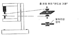
도 2는 전단-충격에 의해 절단된 에지의 도전성 열처리를 위한 시험 설비이고,
도 3은 전단-충격에 의해 절단된 에지의 전도성 열처리 후에 코팅되지 않은 샘플 HDT780C에 대한 ISO 16630에 따른 홀 팽창 시험의 결과이고,
도 4는 레이저에 의한 전단-충격에 의해 절단된 에지의 열처리 후에 용융 코팅된 샘플 HCT780CD 및 코팅되지 않은 샘플 HDT780C에 대한 ISO 16630에 따른 홀 팽창 시험의 결과이고,
도 5는 본 발명에 따라 열처리된 절단된 에지에 대한 미세구조 및 경도 추이이다.Figure 1 is a schematic view of the hole expansion test according to ISO 16630 on heat treated cut edges according to the present invention,
2 is a test fixture for conductive heat treatment of edges cut by shear-impact,
3 is the result of the hole expansion test according to ISO 16630 for a sample HDT780C that has not been coated after the conductive heat treatment of the edge cut by shear-impact,
4 is the result of the hole expansion test according to ISO 16630 for the melt coated sample HCT780CD and the uncoated sample HDT780C after the heat treatment of the edge cut by the shear-shock by the laser,
Figure 5 is a microstructure and hardness trend for a cut edge heat treated in accordance with the present invention.
도 1은 본 발명에 따라 열처리된 절단된 에지에 대한 ISO 16630에 따른 홀 팽창 시험을 개략적으로 도시한다.Figure 1 schematically shows an hole expansion test according to ISO 16630 for a cut edge heat treated in accordance with the present invention.
본 발명에 따르면, 이 열처리는 적절한 크기로 플레이트의 절단 후 및 절단된 에지에 인접한 영역의 성형 전의 중간 단계로서 전단-충격에 의해 절단된 에지에 대해서만 수행된다.According to the invention, this heat treatment is carried out only on the edge cut by shear-impact after cutting of the plate to an appropriate size and as an intermediate step before shaping of the area adjacent to the cut edge.
전단-충격에 의해 절단된 에지의 전도성 열처리를 위한 시험 설비는 도 2에 도시되어 있다.The test setup for the conductive heat treatment of shear-impact cut edges is shown in Fig.
본 시험에서 가열 장치로서 고출력 레이저 외에도 자동차 산업에서 차량의 부품 제조에 사용되는 강 시트를 접합 용접하기 위한 종래의 스폿 용접 기계가 사용되었다. 그러나 본 경우는 상부에 놓여 있는 시트의 용접을 수반하지 안지만, 도 1에 따르면 내부에 펀칭된 홀을 가진 시트(단계 1)가 전단-충격에 의해 절단된 에지의 영역에서 열처리된다(단계 2). 그 후 단계 3에서 다이에 의해 실제의 홀 팽창이 수행되고, 이것은 시험된 프로브에서 결정된다.In the present test, a conventional spot welding machine was used to weld a steel sheet used for manufacturing parts of a vehicle in the automobile industry in addition to a high output laser as a heating device. In this case, however, the sheet having the hole punched therein (step 1) is heat-treated in the region of the edge cut by the shear-impact according to Fig. 1 (step 2) . The actual hole expansion is then carried out by the die in
도 2에 도시된 바와 같이, 대향하는 스폿 용접 전극은 전단-충격을 받은 홀 에지가 열처리될 수 있도록 펀칭된 홀보다 큰 직경을 갖는다. 또한, 홀의 경계와 접촉하는 단부에서 전극은 반원형 형상을 가지므로 한편으로는 플레이트가 용이하게 중심에 배치될 수 있고, 다른 한편으로는 열이 전단-충격을 받은 영역에만 집중적으로 도입될 수 있다.As shown in Fig. 2, the opposing spot welding electrodes have a diameter larger than the hole punched so that the shear-impacted hole edge can be heat-treated. In addition, at the end contacting the boundary of the hole, the electrode has a semicircular shape so that the plate can be easily centered and, on the other hand, heat can be intensively introduced only in the shear-shocked region.
본질적으로 전단-충격을 받은 영역에만 전류를 충돌시키기 위해서, 접촉 전극의 팁의 형상은 에지 영역의 각각의 기하학적 구성에 대해 조절되어야 한다.In order to impact the current only in the essentially shear-shocked region, the shape of the tip of the contact electrode must be adjusted for each geometry of the edge region.
시험을 위해 680 MPa의 최소 항복 강도 및 800 MPa의 최소 인장 강도를 갖는 HDT780C 등급의 코팅되지 않은 고강도 열간 압연된 베이나이트계 강이 사용되었다. 또한, HCT780CD 등급의 500 MPa의 최소 항복 강도 및 780 MPa의 최소 인장 강도를 갖는 용융 아연도금된 냉간 압연된 복합상 강이 사용되었다.For the test, HDT780C grade uncoated high strength, hot rolled bainite steel with a minimum yield strength of 680 MPa and a minimum tensile strength of 800 MPa was used. Hot dip galvanized cold rolled composite steels having a minimum yield strength of 500 MPa and a minimum tensile strength of 780 MPa of the HCT780CD grade were also used.
방법에 따라, 처리 지속시간, 즉, 가열이 유도적으로 수행되는 경우의 전류의 지속시간 및 레이저에 의해 취해지는 전력의 지속시간 또는 다른 열원에 대한 노출 시간은 20 ms 내지 최대 10 s, 그러나 통상적으로 유리하게는100 ms 내지 2000 ms이다. 어떤 경우에도 열처리의 부위에서 600℃ 이상의 온도에 도달하는 것이 중요하다.Depending on the method, the treatment duration, i. E. The duration of the current when the heating is conducted inductively and the duration of the power taken by the laser, or the exposure time to the other heat source is 20 ms to 10 s, Advantageously from 100 ms to 2000 ms. In any case, it is important to reach a temperature of 600 ° C or higher at the heat treatment site.
중요한 방법 파라미터는 처리 지속시간이고, 유도 가열의 경우에 전류는 4 내지 10 kA의 범위이다. 레이저에 의한 열처리의 경우, 10 mm의 직경을 갖는 샘플의 절단된 원형 홀의 1 mm의 경계 폭을 갖는 대략 링 형상이 열처리될 수 있도록 약 12 mm의 원형 영역에 걸쳐 분포된 5 kW의 레이저 출력이 조절되었다.An important method parameter is the processing duration, and in the case of induction heating the current is in the range of 4 to 10 kA. In the case of heat treatment by laser, a laser output of 5 kW distributed over a circular area of about 12 mm so that the roughly ring shape with a 1 mm boundary width of the cut circular holes of the sample having a diameter of 10 mm is heat- .
전단-충격에 의해 절단된 에지의 전도성 열처리 후에 코팅되지 않은 샘플 HDT780C에 대해 ISO 16630에 따른 홀 팽창 시험의 결과는 도 3에 도시되어 있고, 전단-충격에 의해 절단된 에지의 열처리 후의 용융 아연도금된 샘플 HCT780CD 및 코팅된 샘플 HDT780C로 얻어진 대응하는 결과는 도 4에 도시되어 있다.The results of the hole expansion test according to ISO 16630 for the uncoated sample HDT780C after the conductive heat treatment of the edge cut by the shear-impact are shown in Figure 3 and the results of the hot dip galvanizing after the heat treatment of the edge cut by shear- The corresponding results obtained with the sample HCT780CD and the coated sample HDT780C are shown in Fig.
도 3 및 도 4에 도시된 바와 같이, 열처리 후 대부분의 경우에 미처리된 참조 샘플에 비해 2 내지 3 배 이상 만큼 홀 팽창의 증가가 달성될 수 있다. 결과에서의 차이는 특히 최적화되지 않은 기하학적 조건으로 인해 레이저에 의한 균일하지 않은 열처리로 인한 것이다.As shown in FIGS. 3 and 4, an increase in the hole expansion by two to three times or more as compared to the untreated reference sample can be achieved in most cases after the heat treatment. The difference in results is due to non-uniform heat treatment by the laser, especially due to unoptimized geometric conditions.
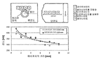
도 5의 좌상측 이미지는 본 발명에 따라 홀 에지 영역이 처리된 금속 플레이트 내에 펀칭된 홀의 개략 평면도를 도시한다. 열 영향 영역 내에 형성되는 미세구조는 우상측 이미지에 개략적으로 도시되어 있다.The upper left image of FIG. 5 shows a schematic plan view of a hole punched in a metal plate in which the hole edge region has been treated in accordance with the present invention. The microstructure formed in the heat affected zone is shown schematically in the upper right side image.
이것은 열처리의 효과를 예시적으로 도시한 것으로, 지배적인 온도에 관한 결론을 도출할 수 있다. 도시된 결과는 베이나이트계 미세구조를 갖는 HDT780C 강의 500 ms의 처리 지속시간 및 8 kA의 전류를 이용한 유도 처리에 관한 것이다.This is an illustrative example of the effect of heat treatment, and conclusions can be drawn regarding the dominant temperature. The illustrated results relate to a treatment duration of 500 ms of the HDT780C steel having a bainite-based microstructure and an inductive treatment using a current of 8 kA.
약 0.5 mm의 인접한 경계 영역에서, 미세구조 100% 마르텐사이트로 형성된다. 결과적으로 Ac3를 초과하는 가열이 수행된 후에 신속한 냉각이 수행되었다. 에지까지의 거리가 증가함에 따라 베이나이트의 비율은 100% 베이나이트가 존재하는 거리를 초과하여 약 2.5 mm의 에지까지의 거리까지 증가한다. 2.5 mm의 에지 거리를 초과하면 미세구조는 더 이상 변태를 겪지 않으므로 Ac2(약 700℃) 미만의 처리 온도가 존재한다.In an adjacent boundary region of about 0.5 mm, the microstructure is formed with 100% martensite. As a result, rapid cooling was performed after heating exceeding Ac3 was performed. As the distance to the edge increases, the ratio of bainite increases to a distance of up to about 2.5 mm beyond the distance that 100% bainite is present. Exceeding an edge distance of 2.5 mm results in a treatment temperature below Ac2 (about 700 ° C) because the microstructure no longer undergoes transformation.
홀 에지의 인접한 영역에서의 경도 증가(도 5의 하측 이미지)는 마이크로-합금된 베이나이트계 핫 스트립의 경우에 전형적이며, 약 500℃-700℃의 온도 범위에서의 나노입자의 후속 석출에 기인된다.The increase in hardness in the adjacent region of the hole edge (lower image in FIG. 5) is typical for micro-alloyed bainitic hot strips and is attributed to the subsequent precipitation of nanoparticles in the temperature range of about 500 ° C. to 700 ° C. do.
종합적으로 본 발명의 장점은 다음과 같이 요약될 수 있다.In summary, the advantages of the present invention can be summarized as follows.
- 감소된 에지 균열 민감도 및 높은 홀 팽창 능력을 가진 매우 우수한 성형가능한 절단된 에지를 생성하며, 이는 복잡한 부품의 기하학적 형상의 제조를 가능하게 하고, 성형 중에 에지 균열에 기인된 스크랩의 위험을 감소시킨다.- produces very good formable cut edges with reduced edge cracking sensitivity and high hole expandability, which enables the production of geometric shapes of complex parts and reduces the risk of scrap due to edge cracking during molding .
- 복잡한 부품의 기하학적 형상을 제조함으로써 경량 및 비용에 관하여 최적화된 생성물을 생성한다.Produce a product optimized for light weight and cost by manufacturing geometric shapes of complex parts.
- 열처리의 지속시간이 매운 짧고, 온도 간격이 매우 넓으므로 프레싱된 부품의 다단계 생산에 본 방법을 통합시킬 수 있는 가능성이 있다.- Because the duration of the heat treatment is short and the temperature interval is very wide, there is a possibility to integrate this method into the multi-stage production of pressed parts.
- 국부적인 그리고 일시적으로 매우 제한된 가열로 인해 부식 방지 코팅된 시트 금속에 본 방법을 적용할 수 있다.- The method can be applied to corrosion resistant coated sheet metal due to localized and temporarily very limited heating.
- 변태 가능 재료에서 통상적으로 출발 재료에 비해 열처리된 영역이 연화되지 않고 강화된다.- Heat-treated areas in the fabricable material are typically strengthened rather than softened relative to the starting material.
Claims (15)
먼저 실온에서 스트립 또는 금속 플레이트로부터 상기 플레이트가 절단되고, 당면한 상황에 따라, 예를 들면, 상기 시트 금속 또는 상기 플레이트 상에 리세스 또는 천공을 얻기 위한 펀칭 또는 절단 작업과 같은 추가의 제조 단계가 수행되고, 후속하여 이렇게 제조된 플레이트가 실온에서 하나 이상의 단계에서 부품으로 성형되고, 상기 부품으로의 성형에 무관하게, 그리고 적절한 크기로 상기 플레이트의 절단 후 및 선택적인 추가의 펀칭이나 절단 작업 후의 임의의 시점에서, 상기 절단 또는 펀칭 작업에 의해 변형 경화된, 그리고 상기 부품의 제조 중에 후속 냉간 성형을 받는 상기 시트 금속의 에지 영역이 600℃ 이상의 온도까지 가열되고, 상기 온도 노출 시간은 10 초 이하인,
부품의 제조 방법.CLAIMS What is claimed is: 1. A method of manufacturing a component by mechanically cutting or punching a plate having high formability and reduced crack sensitivity edges from steel at room temperature,
The plate is first cut from the strip or metal plate at room temperature and additional manufacturing steps are performed such as, for example, a punching or cutting operation to obtain a recess or perforation on the sheet metal or plate, depending on the circumstances And subsequently the thus produced plate is molded into a part at one or more steps at room temperature and the resulting plate is then molded into the part regardless of its molding into the part and after any cutting of the plate to an appropriate size and after optional further punching or cutting operation Wherein the edge region of the sheet metal subjected to subsequent cold forming during the manufacturing of the part is heated to a temperature of at least 600 DEG C and the temperature exposure time is less than or equal to 10 seconds,
A method of manufacturing a component.
상기 온도 노출 시간은 0.02 내지 10 초인,
부품의 제조 방법.The method according to claim 1,
Wherein the temperature exposure time is 0.02 to 10 seconds,
A method of manufacturing a component.
상기 온도 노출 시간은 0.1 내지 2 초인,
부품의 제조 방법.3. The method of claim 2,
Wherein the temperature exposure time is between 0.1 and 2 seconds,
A method of manufacturing a component.
변형 경화된 시트 금속의 에지 영역의 가열은 600℃ 내지 고상선 온도까지 수행되는,
부품의 제조 방법.4. The method according to any one of claims 1 to 3,
Heating of the edge regions of the strain-hardened sheet metal is carried out up to a temperature of 600 ° C to a solidus temperature,
A method of manufacturing a component.
상기 변형 경화된 시트 금속의 에지 영역의 가열은 Ac1의 온도 내지 상기 고상선 온도까지 실시되는,
부품의 제조 방법.5. The method of claim 4,
Wherein heating of the edge region of the deformed and hardened sheet metal is carried out from the temperature of Ac1 to the solidus temperature,
A method of manufacturing a component.
상기 가열은 유도 가열, 전도 가열, 복사 가열, 또는 레이저 조사에 의해 성형 온도까지 수행되는,
부품의 제조 방법.6. The method according to any one of claims 1 to 5,
The heating is carried out up to a molding temperature by induction heating, conduction heating, radiation heating, or laser irradiation.
A method of manufacturing a component.
상기 가열은 저항 용접 장치 또는 레이저에 의해 수행되는,
부품의 제조 방법.The method according to claim 6,
The heating may be performed by a resistance welding device or a laser,
A method of manufacturing a component.
상기 플레이트는 일단계 또는 다단계로 성형되는,
부품의 제조 방법.8. The method according to any one of claims 1 to 7,
Wherein the plate is formed in one step or in multiple steps,
A method of manufacturing a component.
상기 시트 금속 플레이트는 유기 코팅 및/또는 금속 코팅을 갖는,
부품의 제조 방법.9. The method according to any one of claims 1 to 8,
Said sheet metal plate having an organic coating and / or a metal coating,
A method of manufacturing a component.
상기 금속 코팅은 Zn 및/또는 Mn 및/또는 Al 및/또는 Si를 함유하는,
부품의 제조 방법.10. The method of claim 9,
Wherein the metal coating comprises Zn and / or Mn and / or Al and / or Si,
A method of manufacturing a component.
상기 시트 금속의 에지로부터 출발하는 상기 플레이트의 평면 방향으로의 열처리는 상기 시트 금속의 두께에 최대로 대응하는 영역에서 실시되는,
부품의 제조 방법.11. The method according to any one of claims 1 to 10,
Wherein a heat treatment in a plane direction of the plate starting from an edge of the sheet metal is performed in a region corresponding to a maximum thickness of the sheet metal,
A method of manufacturing a component.
상기 열처리 부위의 주위 영역은 산화로부터 보호되는,
부품의 제조 방법.12. The method according to any one of claims 1 to 11,
Wherein the peripheral region of the heat treatment site is protected from oxidation,
A method of manufacturing a component.
산화로부터의 보호를 위해 상기 열처리 주위 영역은 적어도 열 영향 중에 불활성 기체로 세척되는,
부품의 제조 방법.13. The method according to any one of claims 1 to 12,
Wherein said heat-treating peripheral region is washed with an inert gas during at least thermal < RTI ID = 0.0 >
A method of manufacturing a component.
상기 열처리의 부위의 주위 영역은 상기 열 열향 전 및/또는 상기 열 영향 후에 불활성 기체로 추가로 세척되는,
부품의 제조 방법.14. The method of claim 13,
Wherein a peripheral region of the region of the heat treatment is further washed with an inert gas before and /
A method of manufacturing a component.
상기 플레이트는 스트립 또는 금속 플레이트로부터 실온에서 적절한 크기로 기계적으로 절단되고, 리세스나 천공을 얻기 위한 추가의 펀칭 또는 절단 작업이 실온에서 선택적으로 수행되고, 부품으로의 성형 전에, 변형 경화된 상기 절단되거나 펀칭된 시트 금속의 에지는 0.02 내지 10 초 또는 0.1 내지 2 초의 시간에 걸쳐 600℃ 이상의 열처리를 받는,
강으로 제조된 플레이트의 용도.As a use of a plate made of steel for forming into parts at room temperature,
The plate is mechanically cut from the strip or metal plate to an appropriate size at room temperature and further punching or cutting operations to obtain a recess or perforation are optionally performed at room temperature and are pre- The edge of the punched sheet metal is subjected to a heat treatment at 600 占 폚 or more over a period of 0.02 to 10 seconds or 0.1 to 2 seconds,
The use of plates made of steel.
Applications Claiming Priority (3)
| Application Number | Priority Date | Filing Date | Title |
|---|---|---|---|
| DE102014016614.7 | 2014-10-31 | ||
| DE102014016614.7A DE102014016614A1 (en) | 2014-10-31 | 2014-10-31 | Process for producing a component by forming a steel circuit board |
| PCT/DE2015/100414 WO2016066155A1 (en) | 2014-10-31 | 2015-10-06 | Method for producing a component by subjecting a sheet bar of steel to a forming process |
Publications (2)
| Publication Number | Publication Date |
|---|---|
| KR20170077192A true KR20170077192A (en) | 2017-07-05 |
| KR102469605B1 KR102469605B1 (en) | 2022-11-21 |
Family
ID=54359651
Family Applications (1)
| Application Number | Title | Priority Date | Filing Date |
|---|---|---|---|
| KR1020177014382A Active KR102469605B1 (en) | 2014-10-31 | 2015-10-06 | Method for producing a component by subjecting a sheet bar of steel to a forming process |
Country Status (9)
| Country | Link |
|---|---|
| US (1) | US20170333971A1 (en) |
| EP (1) | EP3212348B1 (en) |
| KR (1) | KR102469605B1 (en) |
| CN (1) | CN107208170B (en) |
| DE (1) | DE102014016614A1 (en) |
| ES (1) | ES2701869T3 (en) |
| MX (1) | MX381095B (en) |
| RU (1) | RU2701810C2 (en) |
| WO (1) | WO2016066155A1 (en) |
Families Citing this family (12)
| Publication number | Priority date | Publication date | Assignee | Title |
|---|---|---|---|---|
| DE102016107152B4 (en) | 2016-04-18 | 2017-11-09 | Salzgitter Flachstahl Gmbh | Component of press-hardened aluminum-coated steel sheet and method for producing such a component and its use |
| DE102016121902A1 (en) | 2016-11-15 | 2018-05-17 | Salzgitter Flachstahl Gmbh | Process for the production of chassis parts made of micro-alloyed steel with improved cold workability |
| DE102016121905A1 (en) | 2016-11-15 | 2018-05-17 | Salzgitter Flachstahl Gmbh | Method for producing dual-phase steel wheel discs with improved cold workability |
| DE102017103743A1 (en) * | 2017-02-23 | 2018-08-23 | Salzgitter Flachstahl Gmbh | Method for optimized production of a component with at least one secondary feature |
| DE102017103729A1 (en) | 2017-02-23 | 2018-08-23 | Salzgitter Flachstahl Gmbh | Method for producing a component by further shaping a preformed contour |
| CN111565863A (en) * | 2017-12-25 | 2020-08-21 | 杰富意钢铁株式会社 | Method for producing press-molded article |
| EP3685933B1 (en) * | 2019-01-25 | 2021-09-08 | Toyota Jidosha Kabushiki Kaisha | Method for processing steel plate |
| JP7052743B2 (en) * | 2019-01-25 | 2022-04-12 | トヨタ自動車株式会社 | Steel sheet forming method and punching machine |
| CN113474100B (en) * | 2019-02-27 | 2023-06-16 | 杰富意钢铁株式会社 | Method for manufacturing steel sheet for cold pressing and method for manufacturing press member |
| EP4054777B1 (en) * | 2019-11-08 | 2023-09-13 | Autotech Engineering S.L. | A forming sheet metal part for a vehicle frame and corresponding production method |
| JP7673410B2 (en) | 2021-01-13 | 2025-05-09 | トヨタ自動車株式会社 | Molding method |
| CN119489322B (en) * | 2025-01-17 | 2025-04-25 | 山西鼎荣冷弯型钢有限公司 | Cold roll forming processing technology for stainless steel high-frequency welded pipe of highway guardrail |
Citations (1)
| Publication number | Priority date | Publication date | Assignee | Title |
|---|---|---|---|---|
| US20090235715A1 (en) * | 2008-03-15 | 2009-09-24 | Elringklinger Ag | Method for selectively forming (plastic working) at least one region of a sheet metal layer made from a sheet of spring steel, and a device for carrying out this method |
Family Cites Families (15)
| Publication number | Priority date | Publication date | Assignee | Title |
|---|---|---|---|---|
| RU2063832C1 (en) * | 1994-07-20 | 1996-07-20 | Александр Николаевич Жученко | Method to produce flat pieces with bulges of rail tie plates type |
| DE19619034C2 (en) * | 1995-07-18 | 1998-01-22 | Mannesmann Ag | Process for improving the formability in the production of components from light metal strip |
| US6143241A (en) * | 1999-02-09 | 2000-11-07 | Chrysalis Technologies, Incorporated | Method of manufacturing metallic products such as sheet by cold working and flash annealing |
| RU2230621C2 (en) * | 2002-03-26 | 2004-06-20 | Оренбургский государственный университет | Method for making bent parts and apparatus for performing the same |
| DE102004038626B3 (en) * | 2004-08-09 | 2006-02-02 | Voestalpine Motion Gmbh | Method for producing hardened components from sheet steel |
| BRPI0907450A2 (en) * | 2008-02-07 | 2016-10-18 | Bluescope Steel Ltd | methods for forming a corrosion resistant al-zn-si-mg alloy coating |
| JP5565785B2 (en) * | 2009-03-05 | 2014-08-06 | 株式会社デルタツーリング | Structural material |
| DE102009049155B4 (en) | 2009-10-12 | 2017-01-05 | Bayerische Motoren Werke Aktiengesellschaft | Method for determining the edge crack sensitivity of a sheet metal material and apparatus for producing a test piece from this sheet metal material |
| SE1100523A1 (en) * | 2011-07-06 | 2013-01-02 | Gestamp Hardtech Ab | Ways to heat mold and harden a sheet metal blank |
| JP5327410B1 (en) * | 2011-09-30 | 2013-10-30 | 新日鐵住金株式会社 | High-strength hot-dip galvanized steel sheet with excellent impact resistance and method for producing the same, high-strength galvannealed steel sheet and method for producing the same |
| DE102011054865B4 (en) * | 2011-10-27 | 2016-05-12 | Benteler Automobiltechnik Gmbh | A method of manufacturing a hot-formed and press-hardened automotive body component and motor vehicle body component |
| DE102011054866A1 (en) * | 2011-10-27 | 2013-05-02 | Benteler Automobiltechnik Gmbh | Preparing hot-formed and press-hardened motor vehicle body component, comprises processing metal sheet circuit board from curable sheet steel in hot-forming and press-hardening tool, and forming area in circuit board as embossing region |
| DE102011121904B4 (en) | 2011-12-21 | 2025-06-12 | Volkswagen Aktiengesellschaft | Process for shearing sheet metal with subsequent forming and a cutting tool intended for this purpose |
| DE102012006941B4 (en) * | 2012-03-30 | 2013-10-17 | Salzgitter Flachstahl Gmbh | Method for producing a steel component by hot forming |
| DE102014001979A1 (en) * | 2014-02-17 | 2015-08-20 | Wisco Tailored Blanks Gmbh | Method of laser welding one or more hardenable steel workpieces in the butt joint |
-
2014
- 2014-10-31 DE DE102014016614.7A patent/DE102014016614A1/en not_active Withdrawn
-
2015
- 2015-10-06 ES ES15786860T patent/ES2701869T3/en active Active
- 2015-10-06 CN CN201580059268.5A patent/CN107208170B/en active Active
- 2015-10-06 RU RU2017118583A patent/RU2701810C2/en active
- 2015-10-06 KR KR1020177014382A patent/KR102469605B1/en active Active
- 2015-10-06 WO PCT/DE2015/100414 patent/WO2016066155A1/en not_active Ceased
- 2015-10-06 EP EP15786860.5A patent/EP3212348B1/en active Active
- 2015-10-06 US US15/523,191 patent/US20170333971A1/en not_active Abandoned
- 2015-10-06 MX MX2017005563A patent/MX381095B/en unknown
Patent Citations (1)
| Publication number | Priority date | Publication date | Assignee | Title |
|---|---|---|---|---|
| US20090235715A1 (en) * | 2008-03-15 | 2009-09-24 | Elringklinger Ag | Method for selectively forming (plastic working) at least one region of a sheet metal layer made from a sheet of spring steel, and a device for carrying out this method |
Also Published As
| Publication number | Publication date |
|---|---|
| MX2017005563A (en) | 2017-12-14 |
| RU2701810C2 (en) | 2019-10-01 |
| CN107208170A (en) | 2017-09-26 |
| CN107208170B (en) | 2019-06-14 |
| MX381095B (en) | 2025-03-12 |
| KR102469605B1 (en) | 2022-11-21 |
| EP3212348B1 (en) | 2018-09-12 |
| ES2701869T3 (en) | 2019-02-26 |
| US20170333971A1 (en) | 2017-11-23 |
| RU2017118583A3 (en) | 2019-04-24 |
| RU2017118583A (en) | 2018-11-30 |
| EP3212348A1 (en) | 2017-09-06 |
| WO2016066155A1 (en) | 2016-05-06 |
| DE102014016614A1 (en) | 2016-05-04 |
Similar Documents
| Publication | Publication Date | Title |
|---|---|---|
| KR102469605B1 (en) | Method for producing a component by subjecting a sheet bar of steel to a forming process | |
| JP7299956B2 (en) | Method for manufacturing steel plate for press hardening and method for manufacturing laser welded blank for press hardening | |
| KR101482917B1 (en) | Hot-formed previously welded steel part with very high mechanical resistance, and production method | |
| CN101426612B (en) | Method of producing a welded part having very high mechanical properties from a rolled and coated sheet | |
| US20070163683A1 (en) | Method for producing a component by reshaping a plate, and device for carrying out said method | |
| EP3290533B1 (en) | Structural component of a vehicle and manufacturing method | |
| US20120060982A1 (en) | Method of producing press-hardened structural parts | |
| CN111107960A (en) | Method for joining two blanks, and blank and product obtained | |
| KR20200087229A (en) | Method for manufacturing press-formed products | |
| US10900110B2 (en) | Method for the hot forming of a steel component | |
| US12053815B2 (en) | Method for the production of chassis parts from micro-alloyed steel with improved cold formability | |
| US20100319426A1 (en) | Method for producing press-hardened components for motor vehicles | |
| KR102386137B1 (en) | How to make a part by further shaping a preformed contour | |
| KR101719446B1 (en) | Press-molded article and method for manufacturing same | |
| CA2999634C (en) | Method for producing a zinc-coated steel component for a vehicle | |
| JP2019111567A (en) | Manufacturing method of press forming article | |
| US20180216204A1 (en) | Method for producing a press-quenched component, and press mold | |
| CN113474100B (en) | Method for manufacturing steel sheet for cold pressing and method for manufacturing press member | |
| KR101738985B1 (en) | Hot formed steel part for vehicles and the method for manufacturing the same | |
| KR102276701B1 (en) | Optimized method for manufacturing a part with at least one auxiliary forming element |
Legal Events
| Date | Code | Title | Description |
|---|---|---|---|
| PA0105 | International application |
St.27 status event code: A-0-1-A10-A15-nap-PA0105 |
|
| PG1501 | Laying open of application |
St.27 status event code: A-1-1-Q10-Q12-nap-PG1501 |
|
| A201 | Request for examination | ||
| PA0201 | Request for examination |
St.27 status event code: A-1-2-D10-D11-exm-PA0201 |
|
| E902 | Notification of reason for refusal | ||
| PE0902 | Notice of grounds for rejection |
St.27 status event code: A-1-2-D10-D21-exm-PE0902 |
|
| P11-X000 | Amendment of application requested |
St.27 status event code: A-2-2-P10-P11-nap-X000 |
|
| P13-X000 | Application amended |
St.27 status event code: A-2-2-P10-P13-nap-X000 |
|
| E701 | Decision to grant or registration of patent right | ||
| PE0701 | Decision of registration |
St.27 status event code: A-1-2-D10-D22-exm-PE0701 |
|
| GRNT | Written decision to grant | ||
| PR0701 | Registration of establishment |
St.27 status event code: A-2-4-F10-F11-exm-PR0701 |
|
| PR1002 | Payment of registration fee |
St.27 status event code: A-2-2-U10-U12-oth-PR1002 Fee payment year number: 1 |
|
| PG1601 | Publication of registration |
St.27 status event code: A-4-4-Q10-Q13-nap-PG1601 |
|
| P22-X000 | Classification modified |
St.27 status event code: A-4-4-P10-P22-nap-X000 |