KR20170077317A - Apparatus for controlling autonomous emergency braking system and method thereof - Google Patents
Apparatus for controlling autonomous emergency braking system and method thereof Download PDFInfo
- Publication number
- KR20170077317A KR20170077317A KR1020150187068A KR20150187068A KR20170077317A KR 20170077317 A KR20170077317 A KR 20170077317A KR 1020150187068 A KR1020150187068 A KR 1020150187068A KR 20150187068 A KR20150187068 A KR 20150187068A KR 20170077317 A KR20170077317 A KR 20170077317A
- Authority
- KR
- South Korea
- Prior art keywords
- mode
- aeb
- attribute information
- road
- moving object
- Prior art date
- Legal status (The legal status is an assumption and is not a legal conclusion. Google has not performed a legal analysis and makes no representation as to the accuracy of the status listed.)
- Granted
Links
Images




Classifications
-
- B—PERFORMING OPERATIONS; TRANSPORTING
- B60—VEHICLES IN GENERAL
- B60W—CONJOINT CONTROL OF VEHICLE SUB-UNITS OF DIFFERENT TYPE OR DIFFERENT FUNCTION; CONTROL SYSTEMS SPECIALLY ADAPTED FOR HYBRID VEHICLES; ROAD VEHICLE DRIVE CONTROL SYSTEMS FOR PURPOSES NOT RELATED TO THE CONTROL OF A PARTICULAR SUB-UNIT
- B60W30/00—Purposes of road vehicle drive control systems not related to the control of a particular sub-unit, e.g. of systems using conjoint control of vehicle sub-units
- B60W30/08—Active safety systems predicting or avoiding probable or impending collision or attempting to minimise its consequences
-
- B—PERFORMING OPERATIONS; TRANSPORTING
- B60—VEHICLES IN GENERAL
- B60T—VEHICLE BRAKE CONTROL SYSTEMS OR PARTS THEREOF; BRAKE CONTROL SYSTEMS OR PARTS THEREOF, IN GENERAL; ARRANGEMENT OF BRAKING ELEMENTS ON VEHICLES IN GENERAL; PORTABLE DEVICES FOR PREVENTING UNWANTED MOVEMENT OF VEHICLES; VEHICLE MODIFICATIONS TO FACILITATE COOLING OF BRAKES
- B60T7/00—Brake-action initiating means
- B60T7/12—Brake-action initiating means for automatic initiation; for initiation not subject to will of driver or passenger
-
- B—PERFORMING OPERATIONS; TRANSPORTING
- B60—VEHICLES IN GENERAL
- B60T—VEHICLE BRAKE CONTROL SYSTEMS OR PARTS THEREOF; BRAKE CONTROL SYSTEMS OR PARTS THEREOF, IN GENERAL; ARRANGEMENT OF BRAKING ELEMENTS ON VEHICLES IN GENERAL; PORTABLE DEVICES FOR PREVENTING UNWANTED MOVEMENT OF VEHICLES; VEHICLE MODIFICATIONS TO FACILITATE COOLING OF BRAKES
- B60T7/00—Brake-action initiating means
- B60T7/12—Brake-action initiating means for automatic initiation; for initiation not subject to will of driver or passenger
- B60T7/22—Brake-action initiating means for automatic initiation; for initiation not subject to will of driver or passenger initiated by contact of vehicle, e.g. bumper, with an external object, e.g. another vehicle, or by means of contactless obstacle detectors mounted on the vehicle
-
- B—PERFORMING OPERATIONS; TRANSPORTING
- B60—VEHICLES IN GENERAL
- B60W—CONJOINT CONTROL OF VEHICLE SUB-UNITS OF DIFFERENT TYPE OR DIFFERENT FUNCTION; CONTROL SYSTEMS SPECIALLY ADAPTED FOR HYBRID VEHICLES; ROAD VEHICLE DRIVE CONTROL SYSTEMS FOR PURPOSES NOT RELATED TO THE CONTROL OF A PARTICULAR SUB-UNIT
- B60W10/00—Conjoint control of vehicle sub-units of different type or different function
- B60W10/18—Conjoint control of vehicle sub-units of different type or different function including control of braking systems
-
- B—PERFORMING OPERATIONS; TRANSPORTING
- B60—VEHICLES IN GENERAL
- B60T—VEHICLE BRAKE CONTROL SYSTEMS OR PARTS THEREOF; BRAKE CONTROL SYSTEMS OR PARTS THEREOF, IN GENERAL; ARRANGEMENT OF BRAKING ELEMENTS ON VEHICLES IN GENERAL; PORTABLE DEVICES FOR PREVENTING UNWANTED MOVEMENT OF VEHICLES; VEHICLE MODIFICATIONS TO FACILITATE COOLING OF BRAKES
- B60T2210/00—Detection or estimation of road or environment conditions; Detection or estimation of road shapes
-
- B60W2550/10—
-
- B60W2550/12—
-
- B60W2550/22—
Landscapes
- Engineering & Computer Science (AREA)
- Transportation (AREA)
- Mechanical Engineering (AREA)
- Automation & Control Theory (AREA)
- Chemical & Material Sciences (AREA)
- Combustion & Propulsion (AREA)
- Traffic Control Systems (AREA)
Abstract
본 발명에 의한 AEB 시스템을 제어하기 위한 장치 및 그 방법이 개시된다. 본 발명에 따른 AEB 시스템을 제어하기 위한 장치는 이동체의 위치에 따른 속성 정보에 따라 AEB(Autonomous Emergency Braking)의 모드를 활성화 모드 또는 비활성화 모드로 결정하고, 상기 결정된 모드에 따라 상기 AEB의 활성화 또는 비활성화를 제어하는 제어부; 및 상기 AEB의 모드를 비활성화 모드로 기본 설정하되, 상기 결정된 모드에 따라 상기 AEB의 모드를 상기 활성화 모드 또는 상기 비활성화 모드로 변경 설정하는 설정부를 포함한다.An apparatus and a method for controlling an AEB system according to the present invention are disclosed. The apparatus for controlling an AEB system according to the present invention determines an active mode or an inactive mode of an AEB according to attribute information according to a location of a moving object and activates or deactivates the AEB according to the determined mode ; And a setting unit configured to set the mode of the AEB to the inactivation mode and to change the mode of the AEB to the activation mode or the inactivation mode according to the determined mode.
Description
본 발명은 AEB 시스템 제어 방안에 관한 것으로서, 특히, 속성 정보에 따라 AEB 시스템을 활성화 모드 또는 비활성 모드로 제어하기 위한 장치 및 그 방법에 관한 것이다.The present invention relates to an AEB system control method, and more particularly, to an apparatus and method for controlling an AEB system in an active mode or an inactive mode according to attribute information.
도로교통공단의 조사 자료에 따르면 교통사고 사망자 중 보행자의 사망사고가 전체에서 약 36.5%를 차지하고 있으며, 이와 같은 보행자의 교통사고로 인한 사회적 손실비용은 년간 13조원이 넘는 것으로 평가되고 있다.According to the survey data of the road traffic corporation, the deaths of pedestrians account for 36.5% of all traffic accident deaths, and the cost of social loss due to pedestrian traffic accidents is estimated to exceed 13 trillion won annually.
유럽, 미국, 일본 등 주요국가에서는 보행자의 교통사고를 감소시키기 위하여 안전규제를 강화하고 있는 추세이며, 차량에서 보행자를 감지하여 자동으로 충돌을 방지하기 위한 다양한 첨단 기술들이 도입되고 있다. 특히, 유럽(EU)에서는 보행자 상해 및 사망자를 줄이기 위한 목적으로 AEB 시스템 장착을 의무화하고 있으며, Euro NCAP(New Car Assessment Program)에서는 2014년부터 차량 안전도 평가 항목으로 공식적으로 AEB가 포함되었다.In Europe, USA, Japan and other major countries, safety regulations are being strengthened to reduce pedestrians' traffic accidents. Various advanced technologies are being introduced to prevent collision by detecting pedestrians in vehicles. In particular, in Europe, the AEB system is mandatory for the purpose of reducing pedestrian injuries and deaths, and the Euro NCAP (New Car Assessment Program) officially includes AEB as a vehicle safety assessment item from 2014.
AEB 시스템(Autonomous Emergency Braking System)은 자동 위험감지 브레이크 시스템으로, 선행 차량이 속도를 줄이거나 멈출 경우, 또는 보행자 등의 장애물이 갑자기 나타나는 경우에 운전자의 능동적 지시가 없더라도 차량에서 이를 감지하고 위험 상황을 판단하여 운전자에게 경고를 하거나 자동으로 감속 제어하며, 더 나아가서 차량에서 스스로 브레이크를 작동시켜서 추돌사고를 방지하거나 그 피해를 최소화하는 시스템이다.The Autonomous Emergency Braking System (AEB) is an automatic risk-based braking system that detects when a preceding vehicle stops or stops, or if an obstacle such as a pedestrian suddenly appears, The driver is alerted or controlled to decelerate automatically, and furthermore, the brake is automatically operated in the vehicle to prevent a collision accident or to minimize the damage.
AEB 시스템에서는 차량과 보행자와의 충돌을 방지하기 위해서 보행자의 정확한 감지, 보행자의 이동방향과 이동속도의 정확한 예측 및 그 예측 정보를 바탕으로 충돌가능 여부와 충돌예측 시간을 정확히 판단한 후, 충돌이 예상될 경우 운전자에게 회피 유도를 위해 위험 경고를 출력하거나 충돌 직전에 자동 제동을 수행해야 한다.In the AEB system, it is necessary to accurately determine the collision possibility and the collision prediction time based on the accurate detection of the pedestrian, the precise prediction of the moving direction and the moving speed of the pedestrian, and the prediction information in order to prevent collision between the vehicle and the pedestrian, , The driver should be presented with a warning of danger in order to induce avoidance or perform automatic braking immediately before the crash.
이와 같은 AEB 시스템은 정확한 보행자 감지와 거리 검출을 위해서 다양한 방식의 센서를 사용하고 있으나, 각 방식의 센서 성능에는 한계가 있으며, 특히 야간이나 악천후 또는 각종 지형지물로 인해 보행자를 감지하는데 장애가 있는 환경에서는 센서의 기술적 한계로 인하여 AEB 성능을 담보할 수 없는 문제가 있다.Although the AEB system uses various sensors for precise pedestrian detection and distance detection, there is a limit to the performance of each type of sensor. Especially in an environment where there is obstacle to detecting pedestrians due to nighttime, bad weather or various types of features There is a problem that the AEB performance can not be guaranteed due to the technical limitations of the sensor.
최근 발표된 유로 NCAP의 AEBS 요구사항을 참조하면, 차량이 시속 20-60km로 주행중인 경우에도 보행자의 보행속도가 3-8km/h인 보행자와의 충돌 위험을 탐지할 것을 요구하고 있다. 그러나 차량이 시속 20km 이상으로 주행중 급작스런 보행자의 출현을 감지하여 충돌위험 여부를 판단하고 충돌발생 가능성이 있다고 판정하여 짧은 시간 내에 감속 내지는 급제동을 하기에는 기술적 한계가 존재하며, 특히 보행자가 주차중인 주변 차량에 가려져 있는 경우에는 보행자의 감지에 어려움이 있어서 유로 NCAP의 요구사항을 만족시키기는 매우 어려운 점이 존재한다.Referring to the recently published Euro NCAP AEBS requirements, it is required to detect the risk of collision with a pedestrian with a walking speed of 3-8 km / h, even when the vehicle is running at 20-60 km per hour. However, there is a technical limitation in determining whether there is a risk of a collision by detecting the appearance of a sudden pedestrian while the vehicle is running at a speed of 20 km / h or more and judging that there is a possibility of a collision and decelerating or suddenly braking within a short time. It is very difficult to satisfy the requirements of the Euro NCAP because it is difficult to detect the pedestrian when it is covered.
또한, 유로 NCAP에서 요구하는 CP2 시나리오(Running Child from Nearside from Obstruction)의 경우 주변 정차된 차량에 의해 시야가 완전히 가려진 어린이 보행자를 감지하여 충돌위험에 대응하여야 하는 것으로서, 일반 성인에 비하여 행동 패턴이 불규칙적인 어린이 보행자의 특성과 더불어 크기가 작은 어린이 보행자가 차량에 가려진 상태에서 돌발적으로 주행중인 차량의 전방/측방으로 뛰어나오는 가혹한 환경에서는 AEB 시스템에서 이를 사전 감지하여 충돌을 예방하도록 구현하는데 많은 기술적 제약사항이 존재한다.In the case of the CP2 scenario required by the Euro NCAP, it is necessary to respond to the risk of collision by detecting pedestrians who are completely obscured by the vehicle stopped in the vicinity, and the behavior pattern is irregular In addition to the characteristics of children pedestrians, in the harsh environment where pedestrians with small footprints are hiding in the car and jumping out of the vehicle suddenly running, the AEB system detects it in advance to prevent collision. Lt; / RTI >
미국 특허등록공보 제6,862,537호는 'Sensor fusion system architecture'에 관한 것으로서, 차량 주변의 상황을 파악하기 위한 센서 시스템으로 각각의 다른 특성을 지닌 센서가 차량의 각각의 위치에 배치되며, 이를 통해서 차량 주변의 상황을 파악할 수 있는 다양한 센싱 정보를 획득하고 이를 융합하여 보다 정확한 주변 상황을 인지할 수 있는 기술이 개시되어 있다.U.S. Patent No. 6,862,537 discloses a sensor fusion system architecture, which is a sensor system for detecting the situation around a vehicle. Sensors having different characteristics are disposed at respective positions of the vehicle, A technique of acquiring various sensing information capable of grasping the situation of a sensor and fusing it to recognize a more accurate surrounding situation is disclosed.
그러나, 상기와 같은 종래기술에 따르더라도 주변 정차된 차량에 의해 시야가 완전히 가려진 어린이 보행자를 사전에 감지하고 충돌 위험 여부를 신속히 파악하여 대응하는 것은 여전히 어려움이 있다.However, according to the above conventional art, it is still difficult to detect the pedestrian completely obstructed by the vehicle stopped in the vicinity and detect the risk of collision promptly.
게다가, 이러한 AEB 시스템은 차량의 주행 중에 충돌을 방지하기 위해 항시 운영되기 때문에 차량이 고속으로 주행하는 도로 예컨대, 자동차 전용도로 등에서의 긴급 제동은 더 큰 위험을 초래할 수도 있다.In addition, since such an AEB system is constantly operated to prevent collision during running of the vehicle, emergency braking on a road on which the vehicle is traveling at a high speed, such as an automobile exclusive road, may pose a greater risk.
따라서, 차량의 위치에 따른 속성 정보를 이용하여 자동 긴급 제동을 활성화하기 위한 모드와 비활성화하기 위한 모드를 선택적으로 운영하게 된다면 보다 효율적으로 보행자 보호를 위한 자동 긴급 제동을 운영하는 것이 가능할 것이다.Accordingly, if the mode for activating the automatic emergency braking and the mode for deactivating the automatic emergency braking are selectively operated by using the attribute information according to the position of the vehicle, the automatic emergency braking for pedestrian protection can be operated more efficiently.
따라서 이러한 종래 기술의 문제점을 해결하기 위한 것으로, 본 발명의 목적은 이동체의 위치에 따른 속성 정보를 이용하여 자동 긴급 제동을 활성화하기 위한 모드와 비활성화하기 위한 모드를 선택적으로 운영하도록 한 AEB 시스템을 제어하기 위한 장치 및 그 방법을 제공하는데 있다.SUMMARY OF THE INVENTION Accordingly, the present invention has been made keeping in mind the above problems occurring in the prior art, and an object of the present invention is to provide an AEB system for selectively activating a mode for activating automatic emergency braking and a mode for deactivating, And a method for the same.
본 발명의 다른 목적은 자동 긴급 제동을 활성화하기 위한 모드와 비활성화하기 위한 모드를 선택적으로 운영하되, 보행자의 출현 가능성이 현저히 낮은 지역에서 AEB 시스템을 비활성화하도록 한 AEB 시스템을 제어하기 위한 장치 및 그 방법을 제공하는데 있다.It is another object of the present invention to provide an apparatus and method for controlling an AEB system that selectively activates a mode for activating automatic emergency braking and a mode for deactivating an AEB system in an area where pedestrians' .
그러나 본 발명의 목적은 상기에 언급된 사항으로 제한되지 않으며, 언급되지 않은 또 다른 목적들은 아래의 기재로부터 당업자에게 명확하게 이해될 수 있을 것이다.However, the objects of the present invention are not limited to those mentioned above, and other objects not mentioned can be clearly understood by those skilled in the art from the following description.
상기 목적들을 달성하기 위하여, 본 발명의 한 관점에 따른 AEB 시스템을 제어하기 위한 장치는 이동체의 위치에 따른 속성 정보에 따라 AEB(Autonomous Emergency Braking)의 모드를 활성화 모드 또는 비활성화 모드로 결정하고, 상기 결정된 모드에 따라 상기 AEB의 활성화 또는 비활성화를 제어하는 제어부; 및 상기 결정된 모드에 따라 상기 AEB의 모드를 상기 AEB를 활성화하기 위한 활성화 모드 또는 상기 AEB를 비활성화하기 위한 비활성화 모드로 변경 저장하는 설정부를 포함할 수 있다.In order to achieve the above objects, an apparatus for controlling an AEB system according to an aspect of the present invention determines an active mode or an inactive mode of an AEB (Autonomous Emergency Braking) according to attribute information according to a location of a moving object, A control unit for controlling activation or deactivation of the AEB according to a determined mode; And a setting unit for changing the mode of the AEB according to the determined mode to an active mode for activating the AEB or an inactive mode for deactivating the AEB.
바람직하게, 상기 제어부는 상기 이동체의 위치에 따른 도로 속성 정보에 따라 상기 AEB의 모드를 상기 활성화 모드 또는 상기 비활성화 모드로 결정하는 것을 특징으로 한다.Preferably, the controller determines the mode of the AEB to be the active mode or the inactivation mode according to the road attribute information according to the position of the moving object.
바람직하게, 상기 도로 속정 정보는 차량의 주행 또는 보행자의 보행에 영향을 미칠 수 있는 도로의 용도나 형태에 관련된 정보를 포함하는 것을 특징으로 한다.Preferably, the road-marking information includes information relating to a use or a form of a road that may affect the running of the vehicle or the walking of the pedestrian.
바람직하게, 상기 제어부는 상기 이동체의 위치에 따른 환경 속성 정보를 이용하여 상기 AEB의 모드를 상기 활성화 모드 또는 상기 비활성화 모드로 결정하는 것을 특징으로 한다.Preferably, the controller determines the mode of the AEB as the activation mode or the inactivation mode by using the environment attribute information according to the location of the moving object.
바람직하게, 상기 환경 속성 정보는, 차량의 주행 또는 보행자의 보행에 영향을 미칠 수 있는 도로 주변의 날씨나 환경에 관련된 정보를 포함하는 것을 특징으로 한다.Preferably, the environmental attribute information includes information relating to the weather or the environment around the road, which may affect the running of the vehicle or the walking of the pedestrian.
바람직하게, 상기 제어부는 상기 이동체의 위치에 따른 도로 속성 정보와 환경 속성 정보를 이용하여 상기 AEB의 모드를 상기 활성화 모드 또는 상기 비활성화 모드로 결정하는 것을 특징으로 한다.Preferably, the controller determines the mode of the AEB to be the activation mode or the inactivation mode using the road attribute information and the environment attribute information according to the location of the moving object.
또한, 본 발명에 따른 AEB 시스템을 제어하기 위한 장치는 상기 도로 속성 정보와 상기 환경 속성 정보를 이용하여 보행자 출현 가능성을 판단하는 판단부를 더 포함하고, 상기 제어부는 그 판단한 결과에 따라 상기 AEB의 모드를 상기 활성화 모드 또는 상기 비활성화 모드로 결정하는 것을 특징으로 한다.The apparatus for controlling an AEB system according to the present invention may further include a determination unit for determining a possibility of a pedestrian appearance using the road attribute information and the environment attribute information, Is determined as the activation mode or the inactivation mode.
또한, 본 발명에 따른 AEB 시스템을 제어하기 위한 장치는 상기 도로 속성 정보와 상기 환경 속성 정보마다 기 할당된 가중치를 기반으로 상기 도로 속성 정보와 상기 환경 속성 정보를 결합하여 융합 정보를 생성하는 융합부를 더 포함하고, 상기 판단부는 그 결합한 결과로 생성된 상기 융합 정보를 이용하여 상기 보행자 출현 가능성을 판단하는 것을 특징으로 한다.According to another aspect of the present invention, there is provided an apparatus for controlling an AEB system, the apparatus comprising: a convergence unit for generating the convergence information by combining the road attribute information and the environment attribute information based on the road attribute information and the pre- Wherein the judging unit judges the possibility of the appearance of the pedestrian by using the fusion information generated as a result of the combining.
바람직하게, 상기 융합 정보는 보행자 보행 불가능 여부를 나타내는 값, 상기 센싱값마다 정규화된 가중치, 상기 센싱값마다 정규화된 신뢰도를 포함하는 것을 특징으로 한다.Preferably, the fusion information includes a value indicating whether the pedestrian can not be walked, a weight normalized for each sensing value, and a reliability normalized for each sensing value.
바람직하게, 상기 제어부는 상기 이동체에 장착된 적어도 하나의 센서를 이용하여 상기 이동체의 위치에 따른 속성 정보를 판단하는 것을 특징으로 한다.Preferably, the control unit determines attribute information according to a position of the moving object using at least one sensor mounted on the moving object.
바람직하게, 상기 센서는 네비게이션 기기, 영상 센서, 능동 센서, 및 하이패스 기기 중 적어도 하나를 포함하는 것을 특징으로 한다.Preferably, the sensor includes at least one of a navigation device, an image sensor, an active sensor, and a high-pass device.
바람직하게, 상기 제어부는 상기 이동체에 장착된 적어도 하나의 센서로부터 획득된 센싱값을 입력 받으면, 보조 표지판 또는 경로 정보를 통해 획득한 구간 잔여거리를 이용하여 상기 센싱값이 유효한지를 판단하여, 그 판단한 결과로 유효하면, 입력 받은 상기 센싱값을 이용하여 상기 이동체의 위치에 따른 속성 정보를 판단하는 것을 특징으로 한다.Preferably, when the sensing value obtained from at least one sensor mounted on the mobile body is inputted, the controller determines whether the sensing value is valid using the assistant sign or the section remaining distance obtained through the route information, And if it is found to be valid, determines the attribute information according to the position of the moving object by using the sensed value.
바람직하게, 상기 제어부는 상기 이동체의 위치에 따른 속성 정보에 따라 상기 AEB의 모드를 현재 운영중인 활성화 모드에서 비활성화 모드로 변경할지를 결정하고, 상기 이동체의 위치에 따른 속성 정보와 상기 이동체의 상태를 나타내는 상태 정보에 따라 상기 AEB의 모드를 현재 운영중인 비활성화 모드에서 활성화 모드로 변경할지를 결정하는 것을 특징으로 한다.Preferably, the control unit determines whether to change the mode of the AEB from the currently active active mode to the inactive mode according to the attribute information according to the position of the moving object, and displays attribute information according to the position of the moving object and a state of the moving object And determines whether to change the mode of the AEB from the currently inactive mode to the active mode according to the status information.
본 발명의 다른 한 관점에 따른 AEB 시스템을 제어하기 위한 방법은 이동체의 위치에 따른 속성 정보에 따라 상기 AEB(Autonomous Emergency Braking)의 모드를 활성화 모드 또는 비활성화 모드로 결정하고, 상기 결정된 모드에 따라 상기 AEB의 활성화 또는 비활성화를 제어하는 단계; 및 상기 결정된 모드에 따라 상기 AEB의 모드를 상기 AEB를 활성화하기 위한 활성화 모드 또는 상기 AEB를 비활성화하기 위한 비활성화 모드로 변경 저장하는 하는 단계를 포함할 수 있다.According to another aspect of the present invention, there is provided a method for controlling an AEB system, the method comprising: determining an AEB (Autonomous Emergency Braking) mode as an active mode or a deactivation mode according to attribute information according to a location of a moving object; Controlling activation or deactivation of the AEB; And modifying the mode of the AEB according to the determined mode to an active mode for activating the AEB or an inactive mode for deactivating the AEB.
바람직하게, 상기 제어하는 단계는 상기 이동체의 위치에 따른 도로 속성 정보에 따라 상기 AEB의 모드를 상기 활성화 모드 또는 상기 비활성화 모드로 결정하는 것을 특징으로 한다.Preferably, the controlling step determines the mode of the AEB as the activation mode or the inactivation mode according to the road attribute information according to the position of the moving object.
바람직하게, 상기 도로 속정 정보는 차량의 주행 또는 보행자의 보행에 영향을 미칠 수 있는 도로의 용도나 형태에 관련된 정보를 포함하는 것을 특징으로 한다.Preferably, the road-marking information includes information relating to a use or a form of a road that may affect the running of the vehicle or the walking of the pedestrian.
바람직하게, 상기 제어하는 단계는 상기 이동체의 위치에 따른 환경 속성 정보를 이용하여 상기 AEB의 모드를 상기 활성화 모드 또는 상기 비활성화 모드로 결정하는 것을 특징으로 한다.Preferably, the controlling step determines the mode of the AEB to be the activation mode or the inactivation mode by using the environment attribute information according to the position of the moving object.
바람직하게, 상기 환경 속성 정보는, 차량의 주행 또는 보행자의 보행에 영향을 미칠 수 있는 도로 주변의 날씨나 환경에 관련된 정보를 포함하는 것을 특징으로 한다.Preferably, the environmental attribute information includes information relating to the weather or the environment around the road, which may affect the running of the vehicle or the walking of the pedestrian.
바람직하게, 상기 제어하는 단계는 상기 이동체의 위치에 따른 도로 속성 정보와 환경 속성 정보를 이용하여 상기 AEB의 모드를 상기 활성화 모드 또는 상기 비활성화 모드로 결정하는 것을 특징으로 한다.Preferably, the controlling step determines the mode of the AEB to be the active mode or the inactivation mode by using the road attribute information and the environment attribute information according to the position of the moving object.
바람직하게, 상기 제어하는 단계는 상기 도로 속성 정보와 상기 환경 속성 정보를 이용하여 보행자 출현 가능성을 판단하고, 그 판단한 결과에 따라 상기 AEB의 모드를 상기 활성화 모드 또는 상기 비활성화 모드로 결정하는 것을 특징으로 한다.Preferably, the controlling step determines the possibility of a pedestrian appearance using the road attribute information and the environment attribute information, and determines the mode of the AEB as the activation mode or the deactivation mode according to the determination result. do.
바람직하게, 상기 제어하는 단계는 상기 도로 속성 정보와 상기 환경 속성 정보마다 기 할당된 가중치를 기반으로 상기 도로 속성 정보와 상기 환경 속성 정보를 결합하여 융합 정보를 생성하고, 그 결합한 결과로 생성된 상기 융합 정보를 이용하여 상기 보행자 출현 가능성을 판단하는 것을 특징으로 한다.Preferably, the controlling step generates fusion information by combining the road attribute information and the environment attribute information based on the road attribute information and the pre-assigned weight for each environment attribute information, And the possibility of the appearance of the pedestrian is determined by using the fusion information.
바람직하게, 상기 융합 정보는 보행자 보행 불가능 여부를 나타내는 값, 상기 센싱값마다 정규화된 가중치, 상기 센싱값마다 정규화된 신뢰도를 포함하는 것을 특징으로 한다.Preferably, the fusion information includes a value indicating whether the pedestrian can not be walked, a weight normalized for each sensing value, and a reliability normalized for each sensing value.
바람직하게, 상기 제어하는 단계는 상기 이동체에 장착된 적어도 하나의 센서를 이용하여 상기 이동체의 위치에 따른 속성 정보를 판단하는 것을 특징으로 한다.Preferably, the controlling step determines attribute information according to a position of the moving object using at least one sensor mounted on the moving object.
바람직하게, 상기 센서는 네비게이션 기기, 영상 센서, 능동 센서, 및 하이패스 기기 중 적어도 하나를 포함하는 것을 특징으로 한다.Preferably, the sensor includes at least one of a navigation device, an image sensor, an active sensor, and a high-pass device.
바람직하게, 상기 제어하는 단계는 상기 이동체에 장착된 적어도 하나의 센서로부터 획득된 센싱값을 입력 받으면, 보조 표지판 또는 경로 정보를 통해 획득한 구간 잔여거리를 이용하여 상기 센싱값이 유효한지를 판단하여, 그 판단한 결과로 유효하면, 입력 받은 상기 센싱값을 이용하여 상기 이동체의 위치에 따른 속성 정보를 판단하는 것을 특징으로 한다.Preferably, when the sensing value obtained from at least one sensor mounted on the mobile body is inputted, the controlling step determines whether the sensing value is valid using the assistant sign or the section remaining distance obtained through the route information, And judges attribute information according to the position of the moving object by using the sensed value, when the determination result is valid.
바람직하게, 상기 제어하는 단계는 상기 이동체의 위치에 따른 속성 정보에 따라 상기 AEB의 모드를 현재 운영중인 활성화 모드에서 비활성화 모드로 변경할지를 결정하고, 상기 이동체의 위치에 따른 속성 정보와 상기 이동체의 상태를 나타내는 상태 정보에 따라 상기 AEB의 모드를 현재 운영중인 비활성화 모드에서 활성화 모드로 변경할지를 결정하는 것을 특징으로 한다.Preferably, the controlling step determines whether to change the mode of the AEB from the currently active active mode to the inactive mode according to the attribute information according to the position of the moving object, and displays the attribute information according to the position of the moving object, And determines whether to change the mode of the AEB from the currently inactive mode to the active mode according to the status information.
이를 통해, 본 발명은 이동체의 위치에 따른 속성 정보를 이용하여 자동 긴급 제동을 활성화하기 위한 모드와 비활성화하기 위한 모드를 선택적으로 운영하되, 보행자의 출현 가능성이 현저히 낮은 지역에서 AEB 시스템을 비활성화하도록 함으로써, 보다 효율적으로 자동 긴급 제동 제어가 가능할 수 있는 효과가 있다.Accordingly, the present invention selectively operates the mode for activating and deactivating the automatic emergency braking by using the attribute information according to the position of the moving object, and deactivates the AEB system in an area where the possibility of pedestrians is remarkably low , The automatic emergency braking control can be performed more efficiently.
또한 본 발명은 활성화 모드와 비활성화 모드에 따라 효율적인 자동 긴급 제동의 제어가 가능하기 때문에 운전자의 안전성과 편의성을 향상시킬 수 있는 효과가 있다.Also, since the automatic emergency braking can be controlled efficiently according to the activation mode and the inactivation mode, safety and convenience of the driver can be improved.
또한, 본 발명은 속성 정보에 따라 보행자의 출현 가능성이 현저히 낮은 지역에서 주행하고 있는 경우 비활성화 모드를 운영하기 때문에 보행자의 오인식에 의한 시스템 오작동을 최소화할 수 있는 효과가 있다.Further, according to the present invention, when the vehicle is traveling in an area where the possibility of the appearance of the pedestrian is remarkably low according to the property information, the inactivation mode is operated, thereby minimizing the malfunction of the system due to the false recognition of the pedestrian.
또한, 본 발명은 해당 지역에서 출현 가능성이 높은 다른 종류의 대상을 검출하는데 집중하도록 하여 시스템의 자원을 효율적으로 활용 가능할 수 있는 효과가 있다.In addition, the present invention can concentrate on detecting other kinds of objects that are likely to appear in the area, and thus can efficiently utilize the resources of the system.
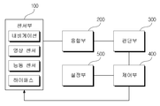
도 1은 본 발명의 일 실시예에 따른 자동 긴급 제동을 제어하기 위한 장치를 나타내는 도면이다.
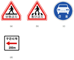
도 2는 본 발명의 일 실시예에 따른 다양한 형태의 표지판을 보여주는 도면이다.
도 3은 본 발명의 일 실시예에 따른 다양한 형태의 도로를 보여주는 도면이다.
도 4a 내지 도 4b는 본 발명의 일 실시예에 따른 신뢰도를 산출하는 원리를 설명하기 위한 도면이다.
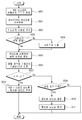
도 5는 본 발명의 일 실시예에 따른 AEB 시스템을 제어하기 위한 방법을 나타내는 제1 도면이다.
도 6은 본 발명의 일 실시예에 따른 AEB 시스템을 제어하기 위한 방법을 나타내는 제2 도면이다.
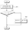
도 7은 본 발명의 일 실시예에 따른 센서값의 유효성 검사 방법을 나타내는 도면이다.
도 8은 본 발명의 다른 실시예에 따른 센서값의 유효성 검사 방법을 나타내는 도면이다.
도 9는 본 발명의 일 실시예에 따라 AEB 시스템의 모드 결정원리를 설명하기 위한 도면이다.
도 10은 본 발명의 다른 실시예에 따라 AEB 시스템의 모드 결정원리를 설명하기 위한 도면이다.1 is a block diagram of an apparatus for controlling automatic emergency braking according to an embodiment of the present invention.
2 is a view showing various types of signs according to an embodiment of the present invention.
3 is a view showing various types of roads according to an embodiment of the present invention.
4A to 4B are diagrams for explaining the principle of calculating reliability according to an embodiment of the present invention.
5 is a first diagram illustrating a method for controlling an AEB system according to an embodiment of the present invention.
6 is a second diagram illustrating a method for controlling an AEB system in accordance with an embodiment of the present invention.
7 is a diagram illustrating a method of validating a sensor value according to an embodiment of the present invention.
8 is a diagram illustrating a method of validating a sensor value according to another embodiment of the present invention.
9 is a view for explaining a mode determination principle of an AEB system according to an embodiment of the present invention.
10 is a view for explaining a mode determination principle of an AEB system according to another embodiment of the present invention.
이하에서는, 본 발명의 실시예에 따른 AEB 시스템을 제어하기 위한 장치 및 그 방법을 첨부한 도면을 참조하여 설명한다. 본 발명에 따른 동작 및 작용을 이해하는 데 필요한 부분을 중심으로 상세히 설명한다.Hereinafter, an apparatus and method for controlling an AEB system according to an embodiment of the present invention will be described with reference to the accompanying drawings. The present invention will be described in detail with reference to the portions necessary for understanding the operation and operation according to the present invention.
또한, 본 발명의 구성 요소를 설명하는 데 있어서, 동일한 명칭의 구성 요소에 대하여 도면에 따라 다른 참조부호를 부여할 수도 있으며, 서로 다른 도면임에도 불구하고 동일한 참조부호를 부여할 수도 있다. 그러나, 이와 같은 경우라 하더라도 해당 구성 요소가 실시예에 따라 서로 다른 기능을 갖는다는 것을 의미하거나, 서로 다른 실시예에서 동일한 기능을 갖는다는 것을 의미하는 것은 아니며, 각각의 구성 요소의 기능은 해당 실시예에서의 각각의 구성 요소에 대한 설명에 기초하여 판단하여야 할 것이다.In describing the constituent elements of the present invention, the same reference numerals may be given to constituent elements having the same name, and the same reference numerals may be given thereto even though they are different from each other. However, even in such a case, it does not mean that the corresponding component has different functions according to the embodiment, or does not mean that the different components have the same function. It should be judged based on the description of each component in the example.
본 명세서에서 이동체는 자동차, 기차 등의 차량과, 청소로봇, 서비스로봇과 같은 로봇을 포함하며, 이동 가능한 장치이면 충분하며, 그 종류에 특별한 제한은 없다. 본 명세서에서 의미하는 객체를 감지하고, AEB시스템은 선행 차량이 속도를 줄이거나 멈출 경우, 또는 보행자/장애물이 갑자기 나타나는 경우에 운전자의 능동적 지시가 없더라도 차량에서 이를 감지하고 위험 상황을 판단하여 운전자에게 경고를 하여 긴급 제동이 가능하도록 유도하거나 또는 자동으로 감속 제어하며, 더 나아가서 차량에서 스스로 브레이크를 작동시켜서 추돌사고를 방지하거나 그 피해를 최소화하는 시스템을 의미하며, AEBS(Autonomous Emergency Braking System) 또는 EBS(Emergency Braking System) 라고 지칭될 수도 있다.In this specification, the moving body includes a vehicle such as an automobile or a train, and a robot such as a cleaning robot or a service robot, and a movable device is sufficient. The AEB system senses the objects referred to in this specification, and the AEB system senses it in the vehicle even if there is no active instruction of the driver when the preceding vehicle stops or stops, or if the pedestrian / obstacle suddenly appears, (AEBS) or EBS (Automatic Braking System) or AEBS (Automatic Emergency Braking System) or EBS (Automatic Braking System) (Emergency Braking System).
또한, 본 명세서에서 의미하는 외부의 객체는, 대표적으로 보행자가 이에 속한다. 보행자는 도로를 보행하거나 노상 작업 중인 자, 노상 유희중인 자, 도로에 서있거나 누워있는 사람, 장애자용 휠체어를 타고 있거나 밀고 가는 사람, 세발 자전거나 모형자동차에 타고 있는 아이 또는 이를 밀고 가는 사람, 이륜차, 원동기 장치자전거, 자전거를 끌고 가는 사람 등 광의의 의미로서 사용되며, 이하에서는 보행자 또는 객체로 정의하여 사용된다. 또한, 본 발명에서 객체는 보도블록이나 가드레일등과 같이 도로 주변에 있는 시설물과 같은 정적인 시설물도 더 포함할 수 있다.In addition, an external object referred to in this specification is typically a pedestrian. Pedestrians are those who are walking on the road or working on the road, people on the street, people standing or lying on the road, persons riding or pushing wheelchairs for disabled persons, children riding on tricycles or model cars, , A prime mover bicycle, a person who pulls a bicycle, etc. In the following, it is defined as a pedestrian or an object. In addition, in the present invention, the object may further include a stationary facility such as a pedestrian block, a guardrail,
특히, 본 발명에서는 이동체의 위치에 따른 속성 정보를 이용하여 AEB 시스템을 활성화하기 위한 활성화 모드(active mode)와 비활성화하기 위한 비활성화 모드(inactive mode)를 선택적으로 운영하되, 보행자의 출현 가능성이 현저히 낮은 지역에서 AEB 시스템을 비활성화하도록 하는 새로운 AEB 제어 방안을 제안한다.In particular, according to the present invention, an active mode for activating the AEB system and an inactive mode for deactivating the AEB system are selectively operated by using the attribute information according to the location of the moving object, and the possibility of appearance of the pedestrian is remarkably low We propose a new AEB control scheme to disable the AEB system in the region.
본 발명에서는 이동체의 위치에 따른 속성 정보를 이용하는데, 속성 정보는 예컨대, 차량이 현재 주행하고 있거나 또는 주행하게 될 도로 속성 정보, 환경 속성 정보 등을 포함할 수 있다. 본 발명에서는 도로 속성 정보와 환경 속성 정보를 이용하는 일 예를 설명하고 있지만, 반드시 이에 한정되지 않고 필요에 따라 다양한 속정 정보를 사용할 수 있다.In the present invention, attribute information according to the position of the moving object is used. For example, the attribute information may include road attribute information, environmental attribute information, and the like, which the vehicle is currently traveling or traveling on. In the present invention, an example of using the road attribute information and the environment attribute information is described, but the present invention is not limited thereto and various types of attribute information can be used as needed.
여기서, 도로 속성 정보는 차량의 주행 또는 보행자의 보행에 영향을 미칠 수 있는 도로의 용도, 형태 등에 관련된 정보를 의미할 수 있고, 환경 속성 정보는 차량의 주행 또는 보행자의 보행에 영향을 미칠 수 있는 도로 주변의 날씨, 환경 등에 관련된 정보를 의미할 수 있다.Here, the road attribute information may mean information relating to the use or form of the road, which may affect the running of the vehicle or the walking of the pedestrian, and the environmental attribute information may be information that may affect the running of the vehicle or the walking of the pedestrian It may mean information related to the weather, environment, etc. around the road.
또한, 본 발명에서는 이러한 다양한 속성 정보를 이용하여 보행자의 출현 가능성을 판단하되, 상태 정보를 추가적으로 더 이용할 수 있다. 여기서, 상태 정보는 차량의 상태에 관련된 정보로서, 예컨대, 속도, 기어 상태 등을 포함할 수 있다.Further, in the present invention, it is possible to determine the appearance possibility of the pedestrian using the various attribute information, and to further use the state information. Here, the state information may include, for example, a speed, a gear state, and the like as information related to the state of the vehicle.
특히, 본 발명은 이러한 도로 속성 정보와 환경 속성 정보 중 적어도 하나를 이용하여 이동체가 주행 중이거나 주행할 도로에 대한 보행자의 출현 가능성을 판단하고 그 판단한 결과에 따라 AEB 시스템의 모드를 활성화 또는 비활성화하고자 한다.Particularly, the present invention uses at least one of the road attribute information and the environment attribute information to judge the possibility of a pedestrian appearing on a road on which a moving object is traveling or a road to be traveled, and to activate or deactivate the mode of the AEB system do.
도 1은 본 발명의 일 실시예에 따른 AEB 시스템을 제어하기 위한 장치를 나타내는 도면이다.1 is a block diagram illustrating an apparatus for controlling an AEB system according to an embodiment of the present invention.
도 1에 도시한 바와 같이, 본 발명에 따른 자동 긴급 제동을 제어하기 위한 장치는 센서부(100), 융합부(200), 판단부(300), 제어부(400), 설정부(500)를 포함할 수 있다.1, an apparatus for controlling automatic emergency braking according to the present invention includes a
센서부(100)는 이동 중인 차량의 외부에 위치하는 객체를 감지하고, 객체 신호를 생성한다. 객체 감지를 위한 센서는 단일의 센서일 수 있고, 복수의 센서일 수 있다. 본 실시예에서 센서부(100)는 영상 센서부(110)와 거리 센서부(120)를 포함할 수 있다. 영상 센서부(110)는 외부의 영상 정보를 객체 신호로서 생성하며, 거리 센서부(120)는 거리 값을 계산할 수 있다. 센서부(100)는 차량 주변의 보행자, 자전거, 유모차 등의 외부 객체 또는 장애물이 존재할 경우, 객체의 존재 여부에 대한 정보, 또는 촬영된 영상 정보, 또는 차량과의 거리 값을 포함하는 객체 신호를 생성한다.The
본 실시예에서 영상 센서부(110)는 적어도 하나 이상의 영상 센서를 포함하도록 구현될 수 있다. 본 명세서의 일 실시예에 따르면 영상 센서부(110)는 FIR(Far Infra Red) 카메라인 제1 영상 센서(111)와 CMOS 카메라(또는 CCD 카메라)인 제2 영상 센서(112)를 포함할 수 있다. 그러나 본 명세서에서는 이에 한정하지 않고 다른 방식의 영상 센서(또는 카메라 센서)를 더 포함할 수도 있다.In this embodiment, the image sensor unit 110 may be implemented to include at least one image sensor. According to one embodiment of the present invention, the image sensor unit 110 may include a first image sensor 111, which is a Far Infra Red (FIR) camera, and a second image sensor 112, which is a CMOS camera have. However, the present invention is not limited thereto and may further include an image sensor (or a camera sensor) of a different method.
CMOS 카메라(또는 CCD 카메라)는 가시광 영역의 빛을 감지하여 투영하는 역할을 하기 때문에 사람의 눈으로 보는 것과 비슷한 영상을 획득한다. 그러나 FIR 카메라는 사람이 보지 못하는 적외선 대역의 빛을 투영하여 영상을 획득한다. 상기 적외선은 빛의 파장 중 750nm에서 1mm의 대역의 빛으로서, 그 중 NIR(Near Infra Red)는 700nm에서 1400nm의 파장을 말하며, FIR의 빛은 LWIR(Long Wavelength Infra Red)라고도 하며, 빛의 파장 중 8μm 에서 15μm의 대역을 나타낸다. 특히 FIR 대역은 온도에 따라 파장이 변하기 때문에 온도를 구별할 수 있는 장점이 있다. 특히 사람의 체온이 10μm의 파장을 가지기 때문에 많이 사용되고 있다.The CMOS camera (or CCD camera) captures images similar to those seen by the human eye because it acts to sense and project light in the visible light range. However, the FIR camera acquires an image by projecting light in an infrared band that a person can not see. The NIR (near infra red) refers to a wavelength of 700 to 1400 nm. The FIR light is also referred to as LWIR (Long Wavelength Infra Red), and the wavelength of light Lt; RTI ID = 0.0 > 8 < / RTI > Particularly, the FIR band has the advantage of distinguishing the temperature because the wavelength changes according to the temperature. Especially, human body temperature is widely used because it has a wavelength of 10μm.
영상 센서부(110)는 주시방향(또는 차량 주행방향)을 촬영하여 외부에서 이동하는 객체(또는 장애물) 영상을 획득한다. 상기 영상 센서부(110)에 포함된 적어도 하나 이상의 영상 센서(111, 112)로부터 획득한 영상은 센서 퓨전 처리부(도시하지 않음)를 통해 영상 퓨전시킴으로써 더 정확하게 이동하는 객체(예: 보행자)의 감지를 수행할 수 있도록 한다. 즉, 상기 영상 퓨전을 통해 각 영상 센서(111, 112)로부터 획득한 영상에서 부족한 부분(예: 정확하지 않은 부분의 영상)을 보완할 수 있도록 함으로써 외부의 객체를 더 정확히 감지할 수 있도록 한다.The image sensor unit 110 acquires an image of an object (or an obstacle) moving from the outside by photographing the viewing direction (or the vehicle traveling direction). The image acquired from the at least one image sensor 111 or 112 included in the image sensor unit 110 is subjected to image fusion through a sensor fusion processing unit (not shown), thereby detecting a more accurately moving object (e.g., a pedestrian) . In other words, it is possible to compensate for a deficient portion (e.g., an incorrect portion of the image) acquired from each of the image sensors 111 and 112 through the image fusion, thereby allowing an external object to be detected more accurately.
예컨대, 영상 센서부(110)는 중앙 분리대 유무, 좌측 또는 우측 가장자리 분리대 유무, 보행 금지, 횡단 금지, 자동차 전용 등을 알려주는 표지판 등의 도로 속성 정보를 제공한다.For example, the image sensor unit 110 provides road attribute information such as the presence or absence of a median separator, the presence or absence of a left or right edge separator, a prohibition of walking, a prohibition of crossing,
도 2는 본 발명의 일 실시예에 따른 다양한 형태의 표지판을 보여주는 도면이다.2 is a view showing various types of signs according to an embodiment of the present invention.
도 2를 참조하면, (a)보행 금지, (b)횡단 금지, (c)자동차 전용도로 임을 각각 알려주는 표지판을 보여주고 있는데, 영상 센서부는 이러한 도로 속성 정보를 제공한다.Referring to FIG. 2, there is shown a sign indicating that (a) is prohibited from walking, (b) is prohibited from crossing, and (c) is an exclusive use road, and the image sensor unit provides such road attribute information.
이때, 영상 센서부가 인식하는 보행 금지, 횡단 금지, 자동차 전용도로를 나타내는 표지판을 일 예로 설명하고 있지만 반드시 이에 한정되지 않고, 이러한 표지판 이외에도 다양한 도로의 속성 정보를 나타낼 수 있는 표지판들이 사용될 수 있다.At this time, for example, signs indicating prohibition of walking, prohibition of traverse, and roads for automobiles recognized by the image sensor are described as an example, but the present invention is not limited thereto. Signs that can display various road attribute information other than these signs may be used.
또한, (d)구간시작 지점을 나타내는 보조 표지판을 보여주고 있는데, 이러한 보조 표지판이 표지판과 함께 사용되기 때문에 이러한 보조 정보 또한 이용할 수 있다.It also shows (d) a supplemental sign indicating the start of the section, and this supplemental information is also available because these supplemental signs are used with signs.
거리 센서부(120)는 적어도 하나 이상의 거리 센서를 포함하여 구성될 수 있다. 본 명세서의 일 실시예에 따르면 거리 센서부(120)는 레이더(Radar) 센서인 제1 거리 센서(121)와 라이다(LIDAR) 센서인 제2 거리 센서(122)를 포함할 수 있다. 그러나 본 명세서에서는 이에 한정하지 않고 다른 방식의 거리 센서(예컨대, 초음파 거리 센서, 적외선 거리 센서 등)를 더 포함할 수도 있다. 라이다(Light Detection And Ranging; LIDAR) 센서는 레이저 펄스를 발사하고, 반사되어 돌아오는 시간을 측정하여 반사체의 위치좌표를 측정하는데 사용할 수 있는 센서이다.The distance sensor unit 120 may include at least one distance sensor. According to an embodiment of the present invention, the distance sensor unit 120 may include a first distance sensor 121 which is a radar sensor and a second distance sensor 122 which is a LIDAR sensor. However, the present invention is not limited to this, and may further include other types of distance sensors (e.g., an ultrasonic distance sensor, an infrared distance sensor, and the like). Light Detection And Ranging (LIDAR) sensors are sensors that can be used to measure the position coordinates of a reflector by emitting laser pulses and measuring the time of reflection and return.
상기 거리 센서부(120)는 주시방향(또는 차량 주행방향)에 있는 객체(또는 장애물)로부터 반사되는 신호를 검출하여 객체(또는 장애물)와 차량간의 거리를 검출한다. 상기 거리 센서부(120)에 포함된 적어도 하나 이상의 거리 센서(121, 122)는 서로 동기화되어 동작한다. 따라서 주시방향에 있는 움직이는 객체(또는 장애물)까지의 거리를 동시에 검출 가능하다. 상기와 같이 동시에 검출된 객체의 거리정보는 어느 하나의 거리 센서에 이상이 있을 경우에 이를 보완할 수 있도록 함으로써 더 높은 신뢰성을 확보할 수 있도록 한다.The distance sensor unit 120 detects a signal reflected from an object (or an obstacle) in the viewing direction (or the vehicle traveling direction) to detect the distance between the object (or obstacle) and the vehicle. At least one of the distance sensors 121 and 122 included in the distance sensor unit 120 operates in synchronization with each other. Therefore, it is possible to simultaneously detect the distance to a moving object (or an obstacle) in the viewing direction. As described above, the distance information of the object detected at the same time can be supplemented when any one of the distance sensors is abnormal, thereby ensuring higher reliability.
예컨대, 거리 센서부(120)는 차로 가장자리까지의 거리 등의 도로 속성 정보를 제공한다.For example, the distance sensor unit 120 provides road attribute information such as the distance to the edge of the lane.
센서부(100)는 레이더 등의 능동 센서부(130)를 포함할 수 있다. 능동 센서부(130)는 전자파의 송수신에 의해 정보를 얻을 수 있는 센서로, 예컨대, 레이더(131)일 수 있다.The
예컨대, 레이더(131)는 차량 레이더로서, 중앙 분리대 유무, 좌측 또는 우측 가장자리 분리대 유무, 및 차로 가장자리까지의 거리 등의 도로 속성 정보를 제공한다.For example, the radar 131 is a vehicle radar, which provides road attribute information such as the presence of a median separator, the presence or absence of a left or right edge separator, and the distance to a car edge.
이때, 차량 레이더는 이동체(차량)에 탑재되어 밀리미터파를 이용하여 전후방 및 측방의 주변환경에 관한 정보를 운전자에게 제공하고 필요한 경우에는 차량을 제어하여 운전자의 안전한 주행을 돕는 데 응용되는 핵심 기술 중의 하나이다.At this time, the vehicle radar is mounted on a moving vehicle (vehicle), and provides information about the surrounding environment around the front and rear using a millimeter wave, and if necessary, controls the vehicle to help the driver to drive safely. It is one.
이러한 차량 레이더를 응용한 기술들은 능동 주행 조정장치(active cruise control), 적응형 주행 조정장치(adaptive cruise control) 또는 지능형 주행 조정 장치(intelligent cruise control) 등으로 불린다. 이들 기술을 차량에 응용하고 있는 대표적인 자동차 업체들은 Daimler-Benz, BMW, Jaguar, Nissan 등이 있다.Technologies employing such a vehicle radar are referred to as active cruise control, adaptive cruise control, or intelligent cruise control. Typical automakers applying these technologies to vehicles are Daimler-Benz, BMW, Jaguar, and Nissan.
차량 레이더에 관한 국제 표준은 ITU-R 권고 M.1452가 있으나 상세한 시스템 사양이나 운용방식 등에 관한 내용은 없고 개괄적인 사항만 언급하여 권고라기보다는 현재 사용되고 있는 차량 레이더에 관한 정리서의 성격을 띠고 있다.The International Standard for Vehicle Radar has ITU-R Recommendation M.1452, but it does not refer to detailed system specifications or operation methods, but rather it refers to the outline, rather than the recommendation, in the nature of the current vehicle radar .
센서부(100)는 네비게이션 기기(140)를 포함할 수 있다. 네비게이션 기기(140)는 차량의 위치 즉, 차량이 현재 주행하고 있거나, 또는 주행하게 될 도로의 속성 정보(이하, 도로 속성 정보)를 제공한다. 네비게이션 기기(140)는 GPS(Global Positioning System) 신호를 수신하는 GPS 수신기(141)와 도로 등의 정보가 저장된 맵 데이터베이스(142)를 포함할 수 있다. 네비게이션 기기(140)는 상용화된 다양한 네비게이션 기기가 존재하며, 도로 속성 정보와 관련된 소프트웨어를 네비게이션 기기에 설치할 경우, 출력값으로서 도로 속성 정보를 제공할 수 있다.The
예컨대, 네비게이션 기기(140)는 자동차전용도로 여부, 고가도로 여부, 국도 여부 등의 도로 속성 정보를 제공한다.For example, the navigation device 140 provides road attribute information such as whether it is an exclusive use road, an elevated road, or a national road.
도 3은 본 발명의 일 실시예에 따른 다양한 형태의 도로를 보여주는 도면이다.3 is a view showing various types of roads according to an embodiment of the present invention.
도 3을 참조하면, (a)국도, (b)자동차 전용도로, (c)보행로는 있으나 우측에 분리대가 존재하는 교각, (d)보행로가 없으며 우측에 분리대가 존재하는 교각을 보여주고 있는데, 네비게이션 기기는 이러한 도로 속성 정보를 제공한다.Referring to FIG. 3, (a) a national road, (b) a motorway, (c) a pier where a walkway exists but there is a pier on the right, (d) a pier with no walkway, The navigation device provides such road attribute information.
이때, 네비게이션 기기가 제공하는 국도, 자동차 전용도로, 교각을 일 예로 설명하고 있지만 반드시 이에 한정되지 않고, 이러한 형태의 도로 이외에도 도로의 속성을 나타낼 수 있는 다양한 형태의 도로들이 도로 속성 정보로서 제공될 수 있다.At this time, although the national road, the exclusive use road, and the bridge pier provided by the navigation device are described as an example, the present invention is not limited to this, and various types of roads capable of representing the attributes of the road may be provided as road attribute information have.
또한, 네비게이션 기기(140)는 차량의 위치 즉, 차량이 현재 주행하고 있거나, 또는 주행하게 될 도로 주변의 환경 속성 정보 예컨대, 날씨, 대기 상태 등을 제공한다.In addition, the navigation device 140 provides environmental attribute information, such as weather, a waiting state, and the like, of the vehicle, that is, the environment around the road on which the vehicle is currently traveling or traveling.
본 실시예에서는 네비게이션 기기가 내적 구성요소로 예시되어 있지만, 네비게이션 기기를 외적 구성요소로 구비하고, 그 네비게이션 기기로부터 도로 속성 정보를 수신하는 방식으로 자동 긴급 제동 기능 제어 장치를 구현할 수도 있다.In this embodiment, although the navigation device is exemplified as an internal component, the automatic emergency braking function control device may be implemented by a method in which the navigation device is provided as an external component and the road attribute information is received from the navigation device.
센서부(100)는 하이패스 기기(150)를 포함할 수 있다. 여기서 하이패스 기기(150)는 대한민국의 고속도로와 유료도로의 통행료를 정차할 필요 없이 무선 통신으로 지불할 수 있도록 하는 시스템의 총칭을 일컫는다. 이러한 하이패스 기기(150)는 차량의 위치 즉, 차량이 주행하게 될 도로의 속성 정보(이하, 도로 속성 정보)를 제공한다.The
예컨대, 하이패스 기기(150)는 유료도로의 진입 또는 진출 등의 도로 속성 정보를 제공한다.For example, the high-pass device 150 provides road attribute information such as entering or advancing a toll road.
센서부(100)는 또한 초음파 센서를 포함할 수도 있다. 특히, 초음파 센서를 구성할 경우, 차량의 후방 경보 시스템(Back Warning Buzzer System;BWS)에서 사용되는 초음파 센서를 사용할 수도 있다.The
초음파 센서는 가정 주파수 대역보다 높은 대역의 주파수를 방사하여 반사되어 오는데 걸리는 시간을 측정함으로써, 객체(또는 장애물)과의 거리를 계산할 수 있다. 통상적으로 초음파 센서는 대략 10m 정도의 감지 거리 및 10도 정도의 지향각을 갖는 고지향각 초음파 센서, 또는 대략 3m 정도의 감지 거리 및 180도 정도의 지향각을 갖는 광지향각 초음파 센서 등 사용 용도에 따라서 다양한 감지거리 및 지향각을 갖도록 특성을 조정할 수 있다.The ultrasonic sensor can calculate the distance to an object (or an obstacle) by measuring the time taken to reflect and radiate a frequency higher than the home frequency band. Generally, an ultrasonic sensor is a high-index ultrasonic sensor having a detection distance of about 10 m and a steering angle of about 10 degrees, or a light-directed ultrasonic sensor having a detection distance of about 3 m and a steering angle of about 180 degrees Therefore, the characteristics can be adjusted to have various detection distances and directivity angles.
초음파 센서는 초음파가 수신되지 않는 대기 상태 동안에는 출력이 HIGH 상태를 유지하다가 트리거 펄스가 인가되는 동시에 버스트(burst) 펄스가 송신되고 출력은 LOW 상태가 된다. 만약 객체(또는 장애물)에 반사된 초음파가 수신되면 다시 출력은 HIGH 상태가 되고 다시 초음파를 수신하기 까지 대기 상태에 진입한다. 객체(또는 장애물)까지의 거리 측정은 LOW 상태인 시간을 측정하여 계산함으로써 구해진다.In the ultrasonic sensor, when the ultrasonic wave is not received, the output of the ultrasonic sensor remains HIGH while the trigger pulse is applied, and at the same time, the burst pulse is transmitted and the output becomes the LOW state. If an ultrasonic wave reflected from an object (or an obstacle) is received, the output becomes HIGH again and enters a standby state again until it receives ultrasonic waves. The distance to the object (or obstacle) is measured by measuring the time in the LOW state.
이처럼 센서부(100)는 이동체의 위치에 따라 도로 속성 정보 또는 환경 속성 정보를 제공할 수 있다. 여기서, 도로 속성 정보는 자동차전용도로 여부, 고가도로 여부, 국도 여부, 중앙 분리대 유무, 좌측 또는 우측 가장자리 분리대 유무, 및 차로 가장자리까지의 거리 등을 포함할 수 있다. 그리고 환경 속성 정보는 낮 또는 밤을 나타내는 시간, 날씨, 기온, 습도, 및 대기 상태 등을 포함할 수 있다.As described above, the
물론, 본 발명에서는 센서부로 영상 센서부, 능동 센서부, 내비게이션 기기, 하이패드 기기를 일 예로 들어 설명하고 있지만 반드시 이에 한정되지 않고 더 추가될 수 있다.Of course, in the present invention, an image sensor unit, an active sensor unit, a navigation device, and a high pad device are described as examples of the sensor unit, but the present invention is not limited thereto.
융합부(200)는 센서부(100)를 구성하는 각종 센서들로부터 센싱값을 전달받아 전달받은 센싱값을 융합할 수 있다. 특히, 융합부(200)는 센서부(100)로부터 전달받은 센싱값을 융합하여 그 융합한 결과로 적어도 하나의 융합 정보를 생성할 수 있다.The
융합부(200)는 하나의 센싱값만을 이용하는 경우 하나의 융합 정보만을 생성할 수 있다. 또한, 본 발명에서는 하나의 센싱값만을 이용하는 경우 융합 정보를 생성하지 않고 센싱값 자체를 이용하여 보행자 출력 가능성을 판단할 수도 있다.The
이때, 융합부(200)에서 생성되는 융합 정보 Fi는 다음의 [수학식 1]과 같이 정의할 수 있다.At this time, the fusion information Fi generated in the
[수학식 1][Equation 1]
Fi = {Bi, wi, pi}Fi = {B i , w i , p i }
여기서, 상기 Bi는 보행자 출현 가능성을 나타내는 값(-1 or 0 or 1)이고, wi는 각 Bi에 대한 센싱값마다 정규화된 가중치를 나타내며, pi는 각 Bi에 대한 정규화된 신뢰도를 나타내는 값(0 ~ 1)이다.Here, Bi represents a value (-1 or 0 or 1) indicative of the possibility of appearance of a pedestrian, wi represents a normalized weight for each sensing value for Bi, pi represents a value indicating normalized reliability for each Bi ~ 1).
이 중 가중치는 임의의 값 또는 일정 범위 내 정규화된 값일 수 있는데, 각 센서로부터 전달되는 정보들의 우선 순위를 고려하여 각 센싱값에 대해 미리 정의될 수 있다.The weight may be an arbitrary value or a normalized value within a certain range, and may be predefined for each sensing value in consideration of the priority of information transmitted from each sensor.
그 일예로, 하이패스 기기에는 1.0, 네비게이션 기기는 0.8, 영상 센서는 0.5 등과 같이 각 센서들로부터 전달되는 정보들에 대한 가중치를 미리 정해 놓을 수 있다.For example, a weight for information transmitted from each sensor such as 1.0 for a high-pass device, 0.8 for a navigation device, and 0.5 for an image sensor can be predetermined.
다른 예로, 하이패스 기기에는 0.4, 네비게이션 기기는 0.4, 영상 센서는 0.2로 정하되, 각 정보들에 대해 부여된 가중치의 전체 합이 1이 되도록 정규화 한다.As another example, the high pass device is set to 0.4, the navigation device is set to 0.4, and the image sensor is set to 0.2, and the sum of the weights given to the respective information is normalized to be 1.
또 다른 예로는 네비게이션 기기 단독으로는 트리거 되지 않고 영상 센서와 함께 적용하는 경우에 트리거 되도록 각 정보의 우선 순위를 고려하여 가중치를 산정한다.As another example, the weight is calculated by considering the priority of each information so that it is triggered when it is applied together with the image sensor without being triggered by the navigation device alone.
그리고 신뢰도는 각 센서로부터 산출된 값을 전달 받거나 융합부에서 산출된다.And the reliability is calculated by the convergence part or by receiving the calculated value from each sensor.
그 일예로, 카메라와 같은 영상 센서나 레이더 등의 ADAS(Advanced Driver Assistance Systems) 센서들은 대상 검출 결과에 대한 신뢰도 정보를 함께 제공한다.For example, ADAS (Advanced Driver Assistance Systems) sensors such as cameras and image sensors provide reliability information on the detection results.
다른 예로, 네비게이션 기기나 하이패스 기기 등은 신뢰도 정보를 제공하지 못하기 때문에 자체적으로 해당 검출 결과에 대한 신뢰도를 산출하는데, GPS 오차범위 내에서 균일한 오차 분포를 가진다고 가정할 때, 오차 범위에서 전용도로 상의 링크가 선택될 수 있는 부분의 비중을 통해 신뢰도를 산출한다.As another example, since the navigation device or the high-pass device can not provide the reliability information, the reliability of the detection result is calculated by itself. Assuming that the GPS device has a uniform error distribution within the GPS error range, The reliability is calculated through the proportion of the portion on the road where the link can be selected.
도 4a 내지 도 4b는 본 발명의 일 실시예에 따른 신뢰도를 산출하는 원리를 설명하기 위한 도면이다.4A to 4B are diagrams for explaining the principle of calculating reliability according to an embodiment of the present invention.
도 4a를 참조하면, GPS 오차 범위(d) 내에서 균일한 오차 분포를 가진다고 가정할 때, 신뢰도 정보를 제공하지 못한 센서의 신뢰도 pi는 다음의 [수학식 2]와 같다.Referring to FIG. 4A, assuming that the sensor has a uniform error distribution in the GPS error range d, the reliability p i of the sensor that does not provide the reliability information is expressed by the following equation (2).
[수학식 2]&Quot; (2) "
pi= (A-B) / Bp i = (AB) / B
여기서, A는 다른 링크로 선택되는 부분을 나타내고, B는 오차 범위를 나타낸다.Here, A represents a portion selected by another link, and B represents an error range.
도 4b를 참조하면, 온라인 실시간성을 고려하여 신뢰도 계산을 근사화할 수 있는데, 표본점(sample point)들 중 전용도로 링크로 매칭되는 점들의 수를 통해 신뢰도를 산출할 수 있다.Referring to FIG. 4B, the reliability calculation can be approximated in consideration of on-line real-time characteristics. Reliability can be calculated from the number of points matched to the dedicated road link among the sample points.
이때, 표본점이 조밀할수록 정확도가 향상되는데, 신뢰도는 다음의 [수학식 3]과 같다.At this time, as the sample point becomes denser, the accuracy improves. The reliability is expressed by the following equation (3).
[수학식 3]&Quot; (3) "
pi= NUM(C) / NUM(T)p i = NUM (C) / NUM (T)
여기서, NUM(T)는 전체 점들의 수를 나타내고, NUM(C)는 전용도로 링크로 매칭되는 점들의 수를 나타낸다.Here, NUM (T) represents the total number of points, and NUM (C) represents the number of points matched to the dedicated road link.
또 다른 예로는 공지된 맵매칭 기술과의 연계를 통한 신뢰도 산출도 가능할 수 있다.As another example, it is possible to calculate the reliability by linking with a known map matching technique.
판단부(300)는 생성된 융합 정보를 이용하여 융합값을 산출하고, 산출된 융합값과 기 설정된 임계치를 비교하여 그 비교한 결과에 따라 보행자 출현 가능성을 판단할 수 있다.The
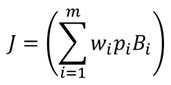
여기서 산출된융합값 J은 다음의 [수학식4] 또는 [수학식 5]와 같이 정의될 수 있다.The fusion value J calculated here can be defined as the following equation (4) or (5).
[수학식 4]&Quot; (4) "

[수학식 5]&Quot; (5) "
이때, 판단부(300)는 상기 비교한 결과로 산출된 융합값이 기 설정된 임계치보다 큰 경우, 보행자 출현 가능성이 현저히 낮은 지역이라고 판단할 수 있다.At this time, if the fused value calculated as the result of the comparison is greater than a predetermined threshold value, the
본 발명에서는 하나의 임계치를 이용하여 보행자 출현 가능성이 현저히 낮은 지역인지를 판단하고 있지만, 반드시 이에 한정되지 않고 필요에 따라 다수의 임계치가 사용될 수 있다.In the present invention, it is judged whether or not the possibility of a pedestrian appearance is remarkably low using one threshold value. However, the present invention is not limited to this, and a plurality of threshold values may be used as needed.
제어부(400)는 판단부로부터 보행자 출현 가능성 판단 결과를 제공 받고 제공 받은 판단 결과에 따라 AEB 시스템의 모드를 활성화 모드 또는 비활성화 모드로 결정하고, 결정된 모드에 따라 AEB 시스템의 활성화 또는 비활성화를 제어할 수 있다.The
예컨대, 제어부(400)는 그 판단 결과로 보행자 출현 가능성이 현저히 낮은 지역이라고 판단된 경우 AEB 시스템의 모드를 비활성화 모드로 결정하여 제어할 수 있다.For example, when it is determined that the pedestrian appearance probability is extremely low as a result of the determination, the
특히, 제어부(400)는 활성화 모드로 운영 중일 때 보행자 출현 가능성이 현저히 낮은 지역이라고 판단되는 경우 AEB 시스템의 모드를 활성화 모드로 결정하여 활성화 모드에서 비활성화 모드로 변경 운영한다.In particular, when it is determined that the pedestrian appearance probability is extremely low when the
반면, 제어부(400)는 그 판단 결과로 보행자 출현 가능성이 현저히 낮은 지역이 아니라고 판단되는 경우 AEB 시스템의 모드를 활성화 모드로 결정하여 제어할 수 있다.On the other hand, if it is determined that the pedestrian appearance possibility is not remarkably low as a result of the determination, the
특히, 제어부(400)는 비활성화 모드로 운영 중일 때 보행자 출현 가능성이 현저히 낮은 지역이 아니라고 판단되는 경우 바로 AEB 시스템의 모드를 활성화 모드로 결정하지 않고, 차량의 상태 정보를 이용하여 기 설정된 상태 조건을 만족하지를 확인하여 그 확인한 결과로 모든 상태 조건을 만족하는 경우에만AEB 시스템의 모드를 활성화 모드로 결정하여 비활성화 모드에서 활성화 모드로 변경 운영한다.In particular, when the
이때, 제어부(400)는 도로속성 정보와 환경 속성 정보를 모두 이용하여 보행자 출현 가능성이 현저히 낮다고 판단되는 경우에만 AEB 시스템을 비활성화할 수 있다.At this time, the
보행자 출현 가능성이 낮은 도로 속성 정보는 속성적 정보 또는 형태적 정보로 구분된다.Road attribute information with low possibility of pedestrian appearance is classified into attribute information or morphological information.
예컨대, 1)속성적 정보는 도로교통법상 고속도로 또는 자동차 전용도로, 기타 보행자의 보행이 금지된 도로 등일 수 있고, 2)형태적 정보는 도로 우측 가장 자리에 가드레일 등 분리대가 있는 교각위 도로, 고가도로, 터널 등인 경우로 여기서 분리대는 가드레일, 콘트리트 방호벽, 녹지대 등 보행자의 보행을 제한하는 모든 형태를 포함하며 또는 도로 중앙에 중앙분리대가 설치되어 있는 경우, 보행자 보행금지 표지판이 설치되어 있는 구간, 자동차 전용도로 표지판이 설치되어 있는 구간 등일 수 있다.For example, 1) the acceleration information may be a highway or an automobile exclusive road in the Road Traffic Act, a road prohibited to be walked by other pedestrians, etc., and 2) a morphological information may be a pier with a guardrail, An elevator, a tunnel, etc., where the separating bar includes all forms of restricting the pedestrian's walking, such as guard rails, concrete barriers, and green areas, or, if a median bar is installed at the center of the road, It may be a section where a road sign for a car is installed.
이때, 제어부(400)는 이동체의 위치에 따라 도로 속성 정보 또는 환경 속성 정보를 이용하여 AEB 시스템의 모드를 결정할 수 있는데, 예컨대, 도로 속성 정보나 환경 속성 정보 중 어느 하나를 이용하여 AEB 시스템의 모드를 결정하거나 도로 속성 정보와 환경 속성 정보를 모두 이용하여 AEB 시스템의 모드를 결정할 수 있다.At this time, the
또한, 제어부(400)는 센서부(100)를 구성하는 각 센서의 특성을 조절할 수도 있다. 이를 위해, 센서부(100)를 구성하는 각 센서는 특성 조절부를 포함할 수 있다. 즉, 특성 조절부가 제어부의 제어에 따라 해당 센서의 특성을 조절할 수 있다.In addition, the
그 일예로, 영상 센서의 경우 보행자 검출에 필요한 리소스를 해당 도로에서 출현 가능성이 높은 다른 객체들의 검출을 위해 활용하도록 차로 내의 영역에서 검출 해상도(resolution)을 조밀하게 설정하고 보행자 검출에 필요한 분류 등의 절차를 생략한다.For example, in the case of an image sensor, resolution is set densely in an area within the lane so as to utilize resources necessary for pedestrian detection for detecting other objects likely to appear on the road, and a classification necessary for pedestrian detection Omit the procedure.
다른 예로, 레이더의 경우 보행자 검출을 위해 다이내믹 레인지(dynamic range)를 크게 설정해야 하는데 이로 인해 노이즈가 개입될 수 있기 때문에 보행자 출현 가능성이 작다고 판단된 경우 민감도 레벨을 낮춰서 노이즈 개입을 최소화할 수 있다.As another example, in the case of a radar, a dynamic range must be set to a large value in order to detect a pedestrian, which may interfere with noise, so that it is possible to minimize noise interference by lowering the sensitivity level when it is determined that pedestrians are unlikely to appear.
또한, 제어부(400)는 센싱값에 따른 객체(보행자와 타 차량)의 공간 정보(위치 또는 속도 정보 등)을 이용하여 전방 충돌 가능성과 후방 충돌 가능성을 예측할 수 있다. 전방 충돌 가능성과 후방 충돌 가능성을 판단하는 방법에 특별한 제한은 없다.In addition, the
예컨대, 전방 충돌 지수, 후방 충돌 지수를 이용하여 전방 충돌 가능성과 후방 충돌 가능성을 계산할 수 있는데, 여기서, 충돌 지수는 충돌 예측 시간일 수 있다.For example, a forward collision probability and a rear collision probability may be calculated using a forward collision index and a backward collision index, where the collision index may be a collision prediction time.
또한, 제어부(400)는 후방 충돌 가능성이 있는 것으로 판단되는 경우, 비상등 또는 미등의 제어 시점을 계산하여 비상등 또는 미등이 동작하도록 제어할 수 있다.In addition, when it is determined that there is a possibility of a rear-end collision, the
그 일예로, 제어부(400)는 후방 충돌 가능성이 있으면 차량의 긴급제동 동작이 발생하기 전에 비상등이 점멸되도록 제어할 수 있고 긴급 제동 동작이 수행된 이후에도 소정 시간동안 지속하여 비상등이 지속적으로 점멸되도록 제어할 수 있다.For example, the
다른 예로, 제어부(400)는 후방 충돌 가능성이 있으면 운전자가 브레이크 페달을 밟지 않더라도 브레이크 등(미등)이 턴온(turn on) 되도록 제어하며 긴급제동 동작이 이루어진 이후에도 소정 시간 동안 지속하여 미등이 턴온 상태를 유지하도록 제어할 수 있다.As another example, the
또한, 제어부(400)는 전방 충돌 가능성이 있으면 제어 신호에 따라 차량의 제어에 직접적으로 개입하여 경고 출력, 종방향 제동(예: 브레이크 제동), 또는 횡방향 제어(예: 차선 변경을 위한 스티어링 휠 제어)를 통해 타 차량과의 충돌을 회피할 수 있도록 한다.If there is a possibility of a forward collision, the
또한, 제어부(400)는 차량이 타 이동체와의 충돌을 회피하기 곤란하다고 판단된 경우, 운전자의 조향 제어가 없더라도 능동적으로 조향 제어를 수행하여 충돌을 회피하도록 스티어링휠을 제어할 수 있다. 예컨대, 센서부를 통해서 현재 주행중인 차선이 횡방향 제어를 하기에 충분한지 차선폭과 차선의 너비 등을 파악하고 옆 차선으로 주행중인 차량이 감지되지 않은 경우에 외부 객체와의 충돌이 예상되는 방향과 멀어지는 각도로 조향각을 설정하여 능동 제어를 수행할 수 있다.In addition, when it is determined that it is difficult for the vehicle to avoid collision with another moving body, the
또한, 제어부(400)는 초기 유량 증대 모듈을 동작시킴으로써 브레이크 작동시 발생되는 응답지연 시간을 최소화하거나 의도적으로 엔진의 응답성을 저하시키거나 출력이 저하되도록 제어함으로써, 긴급 상황에 보다 신속하게 대처할 수 있다.In addition, the
통상적으로 디젤 엔진은 연료 분사량을 제어함으로써 출력을 제어할 수 있으며, 가솔린 엔진의 경우에는 공기량을 제어함으로써 엔진의 출력을 제어할 수 있다. 따라서 디젤 엔진의 경우에는 가속 페달을 조작하게 되면 연료펌프가 조절되어 연료 분사량이 증가되고 연소된 혼합기의 팽창압력이 높아져서 출력이 증가한다. 이때, 연료펌프를 조절하여 연료 분사량이 줄어들도록 제어함으로써 엔진의 출력을 의도적으로 낮출 수 있다.Generally, the diesel engine can control the output by controlling the fuel injection amount, and in the case of the gasoline engine, the output of the engine can be controlled by controlling the air amount. Therefore, in the case of a diesel engine, when the accelerator pedal is operated, the fuel pump is regulated to increase the fuel injection quantity and increase the expansion pressure of the combusted mixer, thereby increasing the output. At this time, the output of the engine can be intentionally lowered by controlling the fuel pump so as to reduce the fuel injection amount.
또한, 가솔린의 경우에는 스로틀밸브의 개도를 조절하여 공기량을 조절함으로써 엔진의 출력을 제어할 수 있다. 이때, 스로틀밸브의 개도를 조절하여 엔진 연소실 내로 흡입되는 공기량을 줄임으로써, 엔진의 출력을 의도적으로 낮출 수 있다.In the case of gasoline, the output of the engine can be controlled by controlling the amount of air by adjusting the opening degree of the throttle valve. At this time, the output of the engine can be intentionally lowered by reducing the amount of air sucked into the engine combustion chamber by adjusting the opening degree of the throttle valve.
설정부(500)는 결정된 모드에 따라 AEB의 모드를 AEB를 활성화하기 위한 활성화 모드 또는 AEB를 비활성화하기 위한 비활성화 모드로 변경하여 저장할 수 있다.The
이때, 설정부(500)는 AEB의 모드를 결정하기 위해 사용할 속성 정보로 기 설정된 도로 속성 정보 또는 환경 속성 정보를 저장할 수 있고 사용자에 의해 변경될 수 있다.At this time, the
그 일예로, 이동체의 속성 정보로 도로 속성 정보 및 환경 속성 정보 중 어느 하나만이 선택되거나 도로 속성 정보 및 환경 속성 정보 모두가 선택되어 저장된다.For example, either the road attribute information or the environment attribute information is selected as the attribute information of the moving object, or both the road attribute information and the environment attribute information are selected and stored.
다른 예로, 이동체의 속성 정보로 도로 속성 정보 및 환경 속성 정보 각각의 일부만이 선택될 수 있는데, 도로 속성 정보의 자동차 전용도로 여부만이 선택되거나 도로 속성 정보의 국도 여부와 환경 속성 정보의 날씨, 대기 상태가 선택되어 저장된다.As another example, only a part of each of the road attribute information and the environment attribute information may be selected as the attribute information of the moving object. State is selected and stored.
도 5는본 발명의 일 실시예에 따른 AEB 시스템을 제어하기 위한 방법을 나타내는 제1 도면이다.5 is a first diagram illustrating a method for controlling an AEB system according to an embodiment of the present invention.
도 5에 도시한 바와 같이, 본 발명에 따른 AEB 시스템을 제어하기 위한 장치(이하, AEB 제어 장치라고 한다)는 활성화 모드로 운영되는 경우(S500), 해당 센서로부터 센싱값을 입력 받을 수 있다(S501).As shown in FIG. 5, when an apparatus for controlling an AEB system according to the present invention (hereinafter referred to as an AEB control apparatus) is operated in an active mode (S500), a sensing value can be input from the sensor S501).
여기서 입력 받은 센싱값은 도로 속성 정보와 환경 속성 정보 중 적어도 하나일 수 있다.Here, the sensing value input may be at least one of the road attribute information and the environment attribute information.
다음으로, AEB 제어 장치는 입력 받은 센싱값의 유효성을 검사할 수 있다(S502).Next, the AEB control device can check the validity of the received sensing value (S502).
다음으로, AEB 제어 장치는 유효성 검사 후 입력된 센싱값 중 신뢰도가 포함되지 않은 센싱값이 있는지를 확인할 수 있다(S503).즉, AEB 제어 장치는 그 확인한 결과로 신뢰도가 포함되지 않은 센싱값이 있으면, 해당 센싱값에 대한 신뢰도를 산출할 수 있다(S504).Next, the AEB control device can check whether there is a sensing value that does not include reliability among the sensing values input after the validity check (S503). That is, the AEB control device determines that the sensing value , The reliability of the sensed value can be calculated (S504).
다음으로, AEB 제어 장치는 그 확인한 결과로 신뢰도가 포함되지 않은 센싱값이 없으면, 입력 받은 센싱값을 이용하여 적어도 하나의 융합 정보를 생성할 수 있다(S505).The AEB controller may generate at least one fusion information using the received sensing value if there is no sensing value that does not include reliability as a result of the checking (S505).
다음으로, AEB 제어 장치는 생성된 융합 정보를 이용하여 융합값(J)을 산출할 수 있다(S506).Next, the AEB control device can calculate the fusion value J using the generated fusion information (S506).
다음으로, AEB 제어 장치는 산출된 융합값(J)과 기 설정된 임계치(Jc)를 비교할 수 있다(S507). 즉, AEB 제어 장치는 그 비교한 결과로 산출된 융합값이 임계치보다 크면 보행자 출현 가능성이 낮은 지역이라고 판단하여 AEB 시스템의 모드를 비활성화 모드로 결정하고(S509), 그렇지 않은 경우 활성화 모드로 계속 운영할 수 있다(S508).Next, the AEB control device can compare the calculated fusion value J with a preset threshold value Jc (S507). That is, if the convergence value calculated as a result of the comparison is greater than the threshold value, the AEB control device determines that the AEB system is in a low-probability region, and determines that the mode of the AEB system is inactivated (S509) (S508).
다음으로, AEB 제어 장치는 상기 결정된 모드에 따라 AEB 시스템의 모드를 비활성화 모드로 변경하고(S510)그 변경된 비활성화 모드를 수행하도록 제어할 수 있다.Next, the AEB control device may change the mode of the AEB system to the inactivation mode according to the determined mode (S510) and perform control to perform the changed inactivation mode.
그리고, AEB 제어 장치는 비활성화 모드에 따라 해당 센서의 특성을 조절할 수 있다(S511).The AEB controller can adjust the characteristics of the sensor according to the inactivation mode (S511).
도 6은 본 발명의 일 실시예에 따른 AEB 시스템을 제어하기 위한 방법을 나타내는 제2 도면이다.6 is a second diagram illustrating a method for controlling an AEB system in accordance with an embodiment of the present invention.
도 6에 도시한 바와 같이, 본 발명에 따른 AEB 시스템을 제어하기 위한 장치(이하, AEB 제어 장치라고 한다)는 비활성화 모드로 운영되는 경우(S600), 해당 센서로부터 센싱값을 입력 받을 수 있다(S601).As shown in FIG. 6, when the apparatus for controlling the AEB system according to the present invention (hereinafter referred to as AEB control apparatus) operates in the inactivation mode (S600), a sensing value can be input from the sensor S601).
여기서 입력 받은 센싱값은 도로 속성 정보와 환경 속성 정보 중 적어도 하나일 수 있다.Here, the sensing value input may be at least one of the road attribute information and the environment attribute information.
다음으로, AEB 제어 장치는 입력 받은 센싱값의 유효성을 검사할 수 있다(S602).Next, the AEB control device can check the validity of the received sensing value (S602).
다음으로, AEB 제어 장치는 유효성 검사 후 입력된 센싱값 중 신뢰도가 포함되지 않은 센싱값이 있는지를 확인할 수 있다(S603). 즉, AEB 제어 장치는 그 확인한 결과로 신뢰도가 포함되지 않은 센싱값이 있으면, 해당 센싱값에 대한 신뢰도를 산출할 수 있다(S604).Next, the AEB controller can check whether there is a sensing value that does not include reliability among the sensing values input after the validity check (S603). That is, if there is a sensing value that does not include the reliability as a result of the checking, the AEB control device can calculate the reliability of the sensing value (S604).
다음으로, AEB 제어 장치는 그 확인한 결과로 신뢰도가 포함되지 않은 센싱값이 없으면, 입력 받은 센싱값을 이용하여 적어도 하나의 융합 정보를 생성할 수 있다(S605).Next, if there is no sensing value that does not include the reliability as a result of the checking, the AEB control device can generate at least one fusion information using the sensing value input (S605).
다음으로, AEB 제어 장치는 생성된 융합 정보를 이용하여 융합값(J)을 산출할 수 있다(S606).Next, the AEB control device can calculate the fusion value J using the generated fusion information (S606).
다음으로, AEB 제어 장치는 산출된 융합값(J)과 기 설정된 임계치(Jc)를 비교할 수 있다(S607). 즉, AEB 제어 장치는 그 비교한 결과로 산출된 융합값이 임계치보다 크면 보행자 출현 가능성이 낮은 지역이라고 판단하여 AEB 시스템의 모드를 비활성화 모드로 계속 운영할 수 있다(S608).Next, the AEB control device can compare the calculated fusion value J with a preset threshold value Jc (S607). That is, if the fused value calculated as the result of the comparison is larger than the threshold value, the AEB control device determines that the possibility of the pedestrian appearance is low, so that the AEB system can continuously operate the mode of the AEB system in the inactive mode (S608).
반면, AEB 제어 장치는 그 비교한 결과로 산출된 융합값이 임계치보다 작으면 차량의 상태 정보를 이용하여 기 설정된 상태 조건을 모두 만족하는지를 확인할 수 있다(S609).On the other hand, if the convergence value calculated as a result of the comparison is smaller than the threshold value, the AEB control device can confirm whether all predetermined condition conditions are satisfied using the vehicle state information (S609).
여기서, 상태 정보는 차량의 상태를 나타내는 정보로서 속도, 기어 상태 등일 수 있다.Here, the state information may be a speed, a gear state, or the like as information indicating the state of the vehicle.
다음으로, AEB 제어 장치는 그 확인한 결과로 상태 조건을 만족하는 경우 AEB 시스템의 모드를 활성화 모드로 결정할 수 있다(S610). 즉, AEB 제어 장치는 융합값이 임계치보다 작고, 기 설정된 적어도 하나의 상태 조건을 모두 만족하는 경우에만AEB 시스템의 모드를 비활성화 모드에서 활성화 모드로 변경할 수 있다.Next, the AEB control device may determine the mode of the AEB system to be the active mode if the status condition is satisfied as a result of the checking (S610). That is, the AEB control apparatus can change the mode of the AEB system from the inactivation mode to the activation mode only when the fusion value is smaller than the threshold and satisfies at least one predetermined condition condition.
그 일예로, 하나의 상태 조건 {VMIN< V < VMAX}, VMIN은 최소 속도, VMAX는 최대 속도로 설정된 경우, AEB 제어 장치는 차량의 속도 V를 이용하여 상태 조건을 만족하는지를 확인하고, 만족하는 경우 AEB 시스템의 모드를 비활성화 모드에서 활성화 모드로 변경한다.For example, when one state condition {V MIN <V <V MAX }, V MIN is set to the minimum speed, and V MAX is set to the maximum speed, the AEB control device checks whether the condition of the vehicle is satisfied by using the vehicle speed V If it is satisfied, the mode of the AEB system is changed from the inactive mode to the active mode.
만약, 상태 조건을 만족하지 못하는 경우에는 AEB 시스템의 모드를 비활성화 모드로 운영한다.If the condition is not satisfied, the AEB system operates in the inactive mode.
다른 예로, 두개의 상태 조건 {VMIN< V < VMAX}, {기어 상태 = 'D(Driver)'}이 설정된 경우, 차량의 속도 V를 이용하여 제1 상태 조건을 만족하는지를 확인하고, 제1 상태 조건을 만족하는 경우 차량의 기어 상태를 이용하여 제2 상태 조건을 만족하는지를 확인함으로써, 제1 상태 조건과 제2 상태 조건 모두를 만족하는 경우 AEB 시스템의 모드를 비활성화 모드에서 활성화 모드로 변경한다.As another example, when two state conditions { V MIN <V <V MAX } and {Gear state = 'D (Driver)'} are set, it is checked whether the first state condition is satisfied using the vehicle speed V, 1 state condition is satisfied, it is determined whether or not the second state condition is satisfied by using the gear state of the vehicle. If the first state condition and the second state condition are satisfied, the mode of the AEB system is changed from the inactive mode to the active mode do.
만약, 제1 상태 조건을 만족하지 못하는 경우에는 AEB 시스템의 모드를 비활성화 모드로 운영한다.If the first condition is not satisfied, the AEB system operates in the inactive mode.
이러한 상태 조건은 사용자에 의해 설정 및 변경이 가능하지만, 설정된 상태 조건을 모두 만족하는 경우에만 AEB 시스템의 모드를 비활성화 모드에서 활성화 모드로의 변경이 가능하다.This state condition can be set or changed by the user, but it is possible to change the mode of the AEB system from the inactive mode to the active mode only when all of the set state conditions are satisfied.
다음으로, AEB 제어 장치는 상기 결정된 모드에 따라 AEB 시스템의 모드를 활성화 모드로 변경하고(S611) 그 변경된 활성화 모드를 수행하도록 제어할 수 있다.Next, the AEB controller changes the mode of the AEB system to the active mode according to the determined mode (S611), and controls the modified AEB mode to perform the changed active mode.
도 7은 본 발명의 일 실시예에 따른 센서값의 유효성 검사 방법을 나타내는 도면이다.7 is a diagram illustrating a method of validating a sensor value according to an embodiment of the present invention.
도 7에 도시한 바와 같이, 보조표지판의 구간거리를 통해 유효성을 검사하는 경우 본 발명에 따른 AEB 시스템을 제어하기 위한 장치(이하, AEB 제어 장치라고 한다)는 보조 표지판의 정보를 이용하여 구간 잔여거리를 획득할 수 있다(S701).As shown in FIG. 7, when the validity is checked through the interval distance of the auxiliary signboard, the apparatus for controlling the AEB system according to the present invention (hereinafter referred to as the AEB control apparatus) The distance can be obtained (S701).
다음으로, AEB 제어 장치는 획득된 구간 잔여거리(Dr)이 0 미만인지를 확인할 수 있다(S702).Next, the AEB control device can confirm whether the acquired section remaining distance Dr is less than 0 (S702).
다음으로, AEB 제어 장치는 그 확인한 결과로 구간 잔여거리가 0 이상이면 보조 표지판의 거리정보를 고려하여 해당 정보를 미검출 상태로 변경할 수 있다(S703).Next, the AEB control apparatus can change the information to the undetected state in consideration of the distance information of the auxiliary signboard if the interval remaining distance is 0 or more as a result of the checking (S703).
이러한 유효성 검사는 센서부 자체에서 이루어거나 융합부에서 이루어질 수 있다.Such validation can be done at the sensor itself or at the fusion site.
도 8은 본 발명의 다른 실시예에 따른 센서값의 유효성 검사 방법을 나타내는 도면이다.8 is a diagram illustrating a method of validating a sensor value according to another embodiment of the present invention.
도 8에 도시한 바와 같이, 네비게이션의 경로정보를 통해 유효성을 검사하는 경우 본 발명에 따른 AEB 시스템을 제어하기 위한 장치(이하, AEB 제어 장치라고 한다)는 네비게이션의 경로정보로부터 구간 잔여거리를 획득할 수 있다(S701).As shown in FIG. 8, when the validity is checked through the route information of the navigation, an apparatus for controlling the AEB system according to the present invention (hereinafter, referred to as an AEB control apparatus) obtains the remaining distance from the navigation route information (S701).
다음으로, AEB 제어 장치는 획득된 구간 잔여거리(Dr)가 오프셋 거리(Dp) 미만인지를 확인할 수 있다(S702).Next, the AEB control device can confirm whether the acquired section remaining distance Dr is less than the offset distance Dp (S702).
이때, 오프셋 거리는 센서 정보 사전 해제를 위한 거리로 센서 인지지연, 운전자 인지에 필요한 시간, 잔여구간 내 추정평균 속도 등을 고려하여 계산될 수 있다.In this case, the offset distance is a distance for releasing the sensor information dictionary, and can be calculated in consideration of the sensor latency, the time required for recognizing the driver, and the estimated average speed in the remaining interval.
다음으로, AEB 제어 장치는 그 확인한 결과로 구간 잔여거리가 오프셋 거리(Dp) 이상이면 네비게이션의 경로정보를 고려하여 해당 정보를 미검출 상태로 변경할 수 있다(S703).Next, the AEB control device can change the information to the non-detection state in consideration of the route information of the navigation when the remaining distance is equal to or greater than the offset distance Dp as a result of the checking (S703).
이러한 유효성 검사는 센서부 자체에서 이루어지거나 융합부에서 이루어질 수 있다.This validation can be done at the sensor itself or at the fusion site.
도 9는본 발명의 일 실시예에 따라 AEB 시스템의 모드 결정원리를 설명하기 위한 도면이다.9 is a view for explaining a mode determination principle of an AEB system according to an embodiment of the present invention.
도 9에 도시한 바와 같이, 본 발명에 따른 AEB 시스템을 제어하기 위한 장치(이하, AEB 제어 장치라고 한다)는 다수의 센서로부터 센싱값을제공 받을 수 있다.As shown in FIG. 9, an apparatus for controlling an AEB system according to the present invention (hereinafter referred to as an AEB control apparatus) can be provided with a sensing value from a plurality of sensors.
여기서, 센서는 네비게이션 기기, 영상 센서, 및 능동 센서를 포함하고 각 센서는 해당 도로 속성 정보에 대한 센싱값을 획득하여 획득된 센싱값을 제공할 수 있다.Here, the sensor includes a navigation device, an image sensor, and an active sensor, and each sensor can provide a sensed value obtained by acquiring a sensed value of the corresponding road attribute information.
예컨대, 네비게이션 기기는 차량이 현재 주행하고 있거나 또는 주행하게 될 도로의 속성 정보로 센싱값 S1 = {고속도로, 신뢰도 없음}을 제공하고, 영상 센서는 도로 속성 정보로 센싱값 S2 = {가장자리 분리대 검출, 신뢰도70%}, S3 = {보행금지 표지판 미검출, 신뢰도 없음}, S4 = {전용도로 표지판 미검출, 신뢰도 없음} 등을 제공하고, 능동 센서는 도로 속성 정보로 센싱값 S8 = {가장자리 분리대 검출, 신뢰도 90%} 등을 제공한다.For example, the navigation device provides the sensed value S1 = {highway, no confidence} as the attribute information of the road on which the vehicle is currently traveling or traveling, and the image sensor provides the sensed value S2 = S4 = {no detection of the road sign, no confidence}}, and the active sensor provides the road attribute information S8 = {edge separation detection , Reliability 90%} and so on.
AEB 제어 장치는 제공 받은 센싱값을 이용하여 적어도 하나의 융합 정보를 생성할 수 있다. 이때, 다수의 센싱값을 제공 받아 5가지 유형의 융합 정보를 생성한다.The AEB controller can generate at least one fusion information using the sensing value provided. At this time, five types of fusion information are generated by receiving a plurality of sensing values.
예컨대, 생성된 5개의 융합 정보는 도로속성 F1 = {1, 0.5, 0.9}, 가장자리분리대 F2 = {1, 0.2, 0.8}, 중앙분리대 F3 = {0, 0.1, -}, 보행금지표지판 F4 = {0, 0.1, -}, 전용도로표지판 F5 = {0, 0.1, -}이다.For example, the five fusion information items generated are the road attribute F1 = {1, 0.5, 0.9}, the edge separator F2 = {1, 0.2, 0.8}, the median separator F3 = {0, 0.1, {0, 0.1, -}, private road sign F5 = {0, 0.1, -}.
AEB 제어 장치는 생성된 5개의 융합 정보를 이용하여 융합값을 산출할 수 있다. 여기서 융합값은 상기 [수학식 4]를 이용하여 산출하면 다음의 [수학식 6]과 같다.The AEB controller can calculate the fusion value using the five fusion information generated. Here, the fused value is calculated by using the above-mentioned expression (4), and is expressed by the following expression (6).
[수학식 6]&Quot; (6) "
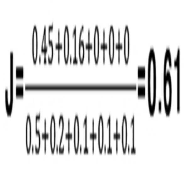
AEB 제어 장치는 이렇게 생성된 융합값을 이용하여 보행자 출현 가능성을 판단할 수 있다.The AEB controller can determine the possibility of pedestrian appearance using the fusion value thus generated.
도 10은 본 발명의 다른 실시예에 따라 AEB 시스템의 모드 결정원리를 설명하기 위한 도면이다.10 is a view for explaining a mode determination principle of an AEB system according to another embodiment of the present invention.
도 10에 도시한 바와 같이, 본 발명에 따른 AEB 시스템을 제어하기 위한 장치(이하, AEB 제어 장치라고 한다)는 다수의 센서로부터 센싱값을 제공 받을 수 있다.As shown in FIG. 10, an apparatus for controlling an AEB system according to the present invention (hereinafter referred to as an AEB control apparatus) can be provided with a sensing value from a plurality of sensors.
예컨대, 네비게이션 기기는 차량이 현재 주행하고 있거나 또는 주행하게 될 도로의 속성 정보로 센싱값 S1 = {고속도로, 신뢰도 없음}을 제공하고, 영상 센서는 도로 속성 정보로 센싱값 S2 = {가장자리 분리대 검출, 신뢰도 70%}, S3 = {보행가능 표지판 검출, 신뢰도 70%}, S4 = {전용도로 표지판 미검출, 신뢰도 없음} 등을 제공하고, 능동 센서는 도로 속성 정보로 센싱값 S8 = {가장자리 분리대 검출, 신뢰도 90%} 등을 제공한다.For example, the navigation device provides the sensed value S1 = {highway, no confidence} as the attribute information of the road on which the vehicle is currently traveling or traveling, and the image sensor provides the sensed value S2 = S4 = {not detected, no confidence}}, and the active sensor is provided with the road attribute information S8 = {edge separation detection, reliability 70%}, S3 = {pedestrian detection, reliability 70%}, , Reliability 90%} and so on.
AEB 제어 장치는 제공 받은 센싱값을 이용하여 적어도 하나의 융합 정보를 생성할 수 있다. 이때, 다수의 센싱값을 제공 받아 5가지 유형의 융합 정보를 생성한다.The AEB controller can generate at least one fusion information using the sensing value provided. At this time, five types of fusion information are generated by receiving a plurality of sensing values.
예컨대, 생성된 5개의 융합 정보는 도로속성 F1 = {1, 0.3, 0.9}, 가장자리분리대 F2 = {1, 0.1, 0.8}, 중앙분리대 F3 = {0, 0.1, -}, 보행가능표지판 F4 = {-1, 0.3, 0.7}, 전용도로표지판 F5 = {0, 0.1, -}이다.For example, the generated five pieces of convergence information include a road attribute F1 = {1, 0.3, 0.9}, an edge separator F2 = {1, 0.1, 0.8}, a median separator F3 = {0, 0.1, {-1, 0.3, 0.7}, private road sign F5 = {0, 0.1, -}.
AEB 제어 장치는 생성된 5개의 융합 정보를 이용하여 융합값을 산출할 수 있다. 여기서 융합값은 상기 [수학식 4]를 이용하여 산출하면 다음의 [수학식 7]과 같다.The AEB controller can calculate the fusion value using the five fusion information generated. Herein, the fusion value is calculated by using the above-mentioned equation (4), and is expressed by the following equation (7).
[수학식 7]&Quot; (7) "
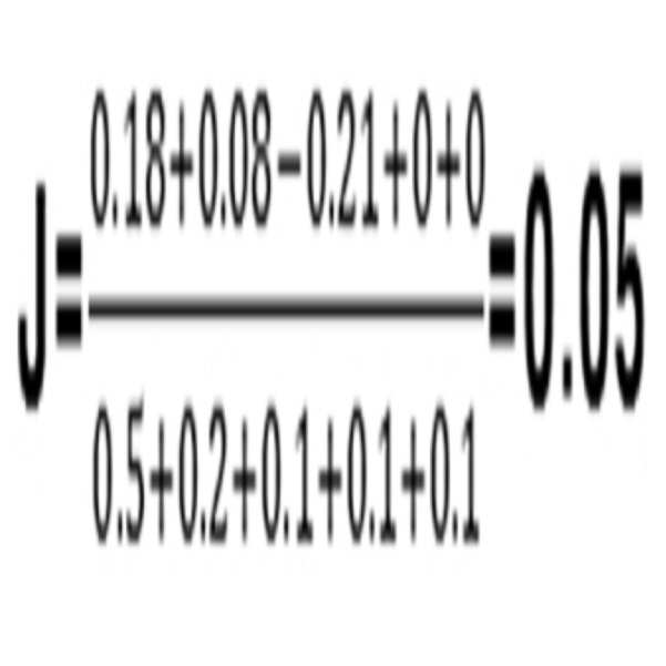
AEB 제어 장치는 이렇게 생성된 융합값을 이용하여 보행자 출현 가능성을 판단할 수 있다.The AEB controller can determine the possibility of pedestrian appearance using the fusion value thus generated.
또한, 본 발명에서는 감지된 센싱값에 따라 AEB 시스템의 구동 여부를 판단하여 AEB 시스템을 구동시키기 위한 활성화 모드 또는 구동시키지 않기 위한 비활성화 모드로 운영하는 방법을 그 일 예로 설명하고 있지만 반드시 이에 한정되지 않고, AEB 시스템이 구동되어 위험을 감지하는 경우에 제동 또는 경고 등을 발생하기 위한 활성화 모드 또는 제동 또는 경고 등을 발생하지 않기 위한 비활성화 모드로 운영될 수도 있다.In the present invention, the AEB system is operated in accordance with the sensed sensed value, and the AEB system is operated in an active mode or in an inactive mode in order to operate the AEB system. However, the present invention is not limited thereto , An activation mode for generating a braking or warning when the AEB system is driven and detecting a danger, or a deactivation mode for not generating a braking or warning.
한편, 이상에서 설명한 본 발명의 실시예를 구성하는 모든 구성 요소들이 하나로 결합하거나 결합하여 동작하는 것으로 기재되어 있다고 해서, 본 발명이 반드시 이러한 실시예에 한정되는 것은 아니다. 즉, 본 발명의 목적 범위 안에서라면, 그 모든 구성 요소들이 하나 이상으로 선택적으로 결합하여 동작할 수도 있다. 또한, 그 모든 구성 요소들이 각각 하나의 독립적인 하드웨어로 구현될 수 있지만, 각 구성 요소들의 그 일부 또는 전부가 선택적으로 조합되어 하나 또는 복수 개의 하드웨어에서 조합된 일부 또는 전부의 기능을 수행하는 프로그램 모듈을 갖는 컴퓨터 프로그램으로서 구현될 수도 있다. 또한, 이와 같은 컴퓨터 프로그램은 USB 메모리, CD 디스크, 플래쉬 메모리 등과 같은 컴퓨터가 읽을 수 있는 저장매체(Computer Readable Media)에 저장되어 컴퓨터에 의하여 읽혀지고 실행됨으로써, 본 발명의 실시예를 구현할 수 있다. 컴퓨터 프로그램의 저장매체로서는 자기 기록매체, 광 기록매체, 캐리어 웨이브 매체 등이 포함될 수 있다.It is to be understood that the present invention is not limited to these embodiments, and all of the elements constituting the embodiments of the present invention described above may be combined or operated in one operation. That is, within the scope of the present invention, all of the components may be selectively coupled to one or more of them. In addition, although all of the components may be implemented as one independent hardware, some or all of the components may be selectively combined to perform a part or all of the functions in one or a plurality of hardware. As shown in FIG. In addition, such a computer program may be stored in a computer-readable medium such as a USB memory, a CD disk, a flash memory, etc., and read and executed by a computer to implement embodiments of the present invention. As the storage medium of the computer program, a magnetic recording medium, an optical recording medium, a carrier wave medium, or the like may be included.
이상에서 설명한 실시예들은 그 일 예로서, 본 발명이 속하는 기술 분야에서 통상의 지식을 가진 자라면 본 발명의 본질적인 특성에서 벗어나지 않는 범위에서 다양한 수정 및 변형이 가능할 것이다. 따라서, 본 발명에 개시된 실시예들은 본 발명의 기술 사상을 한정하기 위한 것이 아니라 설명하기 위한 것이고, 이러한 실시예에 의하여 본 발명의 기술 사상의 범위가 한정되는 것은 아니다. 본 발명의 보호 범위는 아래의 청구범위에 의하여 해석되어야 하며, 그와 동등한 범위 내에 있는 모든 기술 사상은 본 발명의 권리범위에 포함되는 것으로 해석되어야 할 것이다.It will be apparent to those skilled in the art that various modifications and variations can be made in the present invention without departing from the spirit or essential characteristics thereof. Therefore, the embodiments disclosed in the present invention are intended to illustrate rather than limit the scope of the present invention, and the scope of the technical idea of the present invention is not limited by these embodiments. The scope of protection of the present invention should be construed according to the following claims, and all technical ideas within the scope of equivalents should be construed as falling within the scope of the present invention.
100: 센서부
110: 영상 센서부
120: 거리 센서부
130: 능동 센서부
140: 내비게이션 기기
150: 하이패스 기기
200: 융합부
300: 판단부
400: 제어부
500: 설정부100:
110: Image sensor unit
120: Distance sensor unit
130: Active sensor unit
140: Navigation device
150: High-pass device
200: fusion unit
300:
400:
500: Setting section
Claims (26)
상기 결정된 모드에 따라 상기 AEB의 모드를 상기 AEB를 활성화하기 위한 활성화 모드 또는 상기 AEB를 비활성화하기 위한 비활성화 모드로 변경 저장하는 설정부;
를 포함하는 AEB 시스템을 제어하기 위한 장치.A control unit for determining an AEB mode as an active mode or a deactivation mode according to attribute information according to a position of a moving object and controlling activation or deactivation of the AEB according to the determined mode; And
Changing a mode of the AEB according to the determined mode to an active mode for activating the AEB or a deactivating mode for deactivating the AEB;
And an AEB system.
상기 제어부는,
상기 이동체의 위치에 따른 도로 속성 정보에 따라 상기 AEB의 모드를 상기 활성화 모드 또는 상기 비활성화 모드로 결정하는 것을 특징으로 하는 AEB 시스템을 제어하기 위한 장치.The method according to claim 1,
Wherein,
And determining the mode of the AEB as the activation mode or the inactivation mode according to the road attribute information according to the position of the moving object.
상기 도로 속정 정보는, 차량의 주행 또는 보행자의 보행에 영향을 미칠 수 있는 도로의 용도나 형태에 관련된 정보를 포함하는 것을 특징으로 하는 AEB 시스템을 제어하기 위한 장치.3. The method of claim 2,
Wherein the road-marking information includes information related to a use or a form of a road that may affect the running of a vehicle or the walking of a pedestrian.
상기 제어부는,
상기 이동체의 위치에 따른 환경 속성 정보를 이용하여 상기 AEB의 모드를 상기 활성화 모드 또는 상기 비활성화 모드로 결정하는 것을 특징으로 하는 AEB 시스템을 제어하기 위한 장치.The method according to claim 1,
Wherein,
Wherein the control unit determines the mode of the AEB as the activation mode or the inactivation mode using environment attribute information according to the position of the moving object.
상기 환경 속성 정보는, 차량의 주행 또는 보행자의 보행에 영향을 미칠 수 있는 도로 주변의 날씨나 환경에 관련된 정보를 포함하는 것을 특징으로 하는 AEB 시스템을 제어하기 위한 장치.5. The method of claim 4,
Wherein the environment attribute information includes information related to a weather or an environment around the road that may affect the running of the vehicle or the walking of the pedestrian.
상기 제어부는,
상기 이동체의 위치에 따른 도로 속성 정보와 환경 속성 정보를 이용하여 상기 AEB의 모드를 상기 활성화 모드 또는 상기 비활성화 모드로 결정하는 것을 특징으로 하는 AEB 시스템을 제어하기 위한 장치.The method according to claim 1,
Wherein,
And determining the mode of the AEB as the activation mode or the inactivation mode using the road attribute information and the environment attribute information according to the location of the moving object.
상기 도로 속성 정보와 상기 환경 속성 정보를 이용하여 보행자 출현 가능성을 판단하는 판단부;
를 더 포함하고,
상기 제어부는 그 판단한 결과에 따라 상기 AEB의 모드를 상기 활성화 모드 또는 상기 비활성화 모드로 결정하는 것을 특징으로 하는 AEB 시스템을 제어하기 위한 장치.The method according to claim 6,
A determination unit for determining a possibility of a pedestrian appearance using the road attribute information and the environment attribute information;
Further comprising:
Wherein the control unit determines the mode of the AEB as the activation mode or the inactivation mode according to the determination result.
상기 도로 속성 정보와 상기 환경 속성 정보마다 기 할당된 가중치를 기반으로 상기 도로 속성 정보와 상기 환경 속성 정보를 결합하여 융합 정보를 생성하는 융합부;
를 더 포함하고,
상기 판단부는 그 결합한 결과로 생성된 상기 융합 정보를 이용하여 상기 보행자 출현 가능성을 판단하는 것을 특징으로 하는 AEB 시스템을 제어하기 위한 장치.8. The method of claim 7,
A fusion unit for generating fusion information by combining the road attribute information and the environment attribute information based on the road attribute information and a pre-assigned weight for each environment attribute information;
Further comprising:
Wherein the determination unit determines the possibility of the pedestrian appearance using the fusion information generated as a result of the combining.
상기 융합 정보는,
보행자 보행 불가능 여부를 나타내는 값, 상기 센싱값마다 정규화된 가중치, 상기 센싱값마다 정규화된 신뢰도를 포함하는 것을 특징으로 하는 AEB 시스템을 제어하기 위한 장치.9. The method of claim 8,
The fusion information includes:
A value indicating whether the pedestrian can walk or not, a normalized weight for each sensing value, and a normalized reliability for each sensing value.
상기 제어부는,
상기 이동체에 장착된 적어도 하나의 센서로부터 획득된 센싱값 이용하여 상기 이동체의 위치에 따른 속성 정보를 판단하는 것을 특징으로 하는 AEB 시스템을 제어하기 위한 장치.The method according to claim 1,
Wherein,
Wherein the attribute information is determined based on a position of the moving object by using a sensing value obtained from at least one sensor mounted on the moving object.
상기 센서는, 네비게이션 기기, 영상 센서, 능동 센서, 및 하이패스 기기 중 적어도 어느 하나를 포함하는 것을 특징으로 하는 AEB 시스템을 제어하기 위한 장치.11. The method of claim 10,
Wherein the sensor comprises at least one of a navigation device, an image sensor, an active sensor, and a high-pass device.
상기 제어부는,
상기 이동체에 장착된 적어도 하나의 센서로부터 획득된 센싱값을 입력 받으면, 보조 표지판 또는 경로 정보를 통해 획득한 구간 잔여거리를 이용하여 상기센싱값이 유효한지를 판단하여,
그 판단한 결과로 유효하면, 입력 받은 상기 센싱값을 이용하여 상기 이동체의 위치에 따른 속성 정보를 판단하는 것을 특징으로 하는 AEB 시스템을 제어하기 위한 장치.11. The method of claim 10,
Wherein,
When the sensing value obtained from at least one sensor mounted on the mobile body is inputted, it is determined whether the sensing value is valid using the assistant sign or the remaining distance obtained through the route information,
And if it is determined to be valid, determines the attribute information according to the position of the moving object by using the sensed value.
상기 제어부는,
상기 이동체의 위치에 따른 속성 정보에 따라 상기 AEB의 모드를 현재 운영중인 활성화 모드에서 비활성화 모드로 변경할지를 결정하고,
상기 이동체의 위치에 따른 속성 정보와 상기 이동체의 상태를 나타내는 상태 정보에 따라 상기 AEB의 모드를 현재 운영중인 비활성화 모드에서 활성화 모드로 변경할지를 결정하는 것을 특징으로 하는 AEB 시스템을 제어하기 위한 장치.The method according to claim 1,
Wherein,
Determines whether to change the mode of the AEB from the currently active mode to the inactive mode according to the attribute information according to the position of the moving object,
And determines whether to change the mode of the AEB from the currently inactive mode to the active mode according to the attribute information according to the position of the moving object and the state information indicating the state of the moving object.
상기 결정된 모드에 따라 상기 AEB의 모드를 상기 AEB를 활성화하기 위한 활성화 모드 또는 상기 AEB를 비활성화하기 위한 비활성화 모드로 변경 저장하는 하는 단계;
를 포함하는 AEB 시스템을 제어하기 위한 방법.Determining an active mode or an inactive mode of the AEB according to attribute information according to the position of the moving object and controlling activation or deactivation of the AEB according to the determined mode; And
Changing the mode of the AEB to the active mode for activating the AEB or the inactive mode for deactivating the AEB according to the determined mode;
Gt; AEB < / RTI >
상기 제어하는 단계는,
상기 이동체의 위치에 따른 도로 속성 정보에 따라 상기 AEB의 모드를 상기 활성화 모드 또는 상기 비활성화 모드로 결정하는 것을 특징으로 하는 AEB 시스템을 제어하기 위한 방법.15. The method of claim 14,
Wherein the controlling comprises:
And determining the mode of the AEB as the activation mode or the inactivation mode according to the road attribute information according to the position of the moving object.
상기 도로 속정 정보는, 차량의 주행 또는 보행자의 보행에 영향을 미칠 수 있는 도로의 용도나 형태에 관련된 정보를 포함하는 것을 특징으로 하는 AEB 시스템을 제어하기 위한 방법.16. The method of claim 15,
Wherein the road-marking information includes information related to a use or a form of a road that may affect the running of a vehicle or the walking of a pedestrian.
상기 제어하는 단계는,
상기 이동체의 위치에 따른 환경 속성 정보를 이용하여 상기 AEB의 모드를 상기 활성화 모드 또는 상기 비활성화 모드로 결정하는 것을 특징으로 하는 AEB 시스템을 제어하기 위한 방법.15. The method of claim 14,
Wherein the controlling comprises:
Wherein the mode of the AEB is determined to be the active mode or the inactivation mode using environment attribute information according to the position of the moving object.
상기 환경 속성 정보는, 차량의 주행 또는 보행자의 보행에 영향을 미칠 수 있는 도로 주변의 날씨나 환경에 관련된 정보를 포함하는 것을 특징으로 하는 AEB 시스템을 제어하기 위한 방법.18. The method of claim 17,
Wherein the environmental attribute information includes information related to a weather or an environment around the road which may affect the running of the vehicle or the walking of the pedestrian.
상기 제어하는 단계는,
상기 이동체의 위치에 따른 도로 속성 정보와 환경 속성 정보를 이용하여 상기 AEB의 모드를 상기 활성화 모드 또는 상기 비활성화 모드로 결정하는 것을 특징으로 하는 AEB 시스템을 제어하기 위한 방법.15. The method of claim 14,
Wherein the controlling comprises:
Wherein the mode of the AEB is determined to be the active mode or the inactivation mode by using the road attribute information and the environment attribute information according to the position of the moving object.
상기 제어하는 단계는,
상기 도로 속성 정보와 상기 환경 속성 정보를 이용하여 보행자 출현 가능성을 판단하고,
그 판단한 결과에 따라 상기 AEB의 모드를 상기 활성화 모드 또는 상기 비활성화 모드로 결정하는 것을 특징으로 하는 AEB 시스템을 제어하기 위한 방법.20. The method of claim 19,
Wherein the controlling comprises:
Judges the possibility of appearance of a pedestrian using the road attribute information and the environment attribute information,
And determining the mode of the AEB as the activation mode or the inactivation mode according to the determination result.
상기 제어하는 단계는,
상기 도로 속성 정보와 상기 환경 속성 정보마다 기 할당된 가중치를 기반으로 상기 도로 속성 정보와 상기 환경 속성 정보를 결합하여 융합 정보를 생성하고,
그 결합한 결과로 생성된 융합 정보를 이용하여 상기 보행자 출현 가능성을 판단하는 것을 특징으로 하는 AEB 시스템을 제어하기 위한 방법.21. The method of claim 20,
Wherein the controlling comprises:
The road attribute information and the environment attribute information are combined based on the road attribute information and the pre-assigned weight for each environment attribute information to generate fusion information,
And the possibility of appearance of the pedestrian is determined using the fusion information generated as a result of the combining.
상기 융합 정보는,
보행자 보행 불가능 여부를 나타내는 값, 상기 센싱값마다 정규화된 가중치, 상기 센싱값마다 정규화된 신뢰도를 포함하는 것을 특징으로 하는 AEB 시스템을 제어하기 위한 방법.22. The method of claim 21,
The fusion information includes:
A value representative of whether or not pedestrian walking is possible, a normalized weight for each sensing value, and a normalized reliability for each sensing value.
상기 제어하는 단계는,
상기 이동체에 장착된 적어도 하나의 센서로부터 획득된 센싱값 이용하여 상기 이동체의 위치에 따른 속성 정보를 판단하는 것을 특징으로 하는 AEB 시스템을 제어하기 위한 방법.15. The method of claim 14,
Wherein the controlling comprises:
Wherein the attribute information based on the position of the moving object is determined using a sensing value obtained from at least one sensor mounted on the moving object.
상기 센서는, 네비게이션 기기, 영상 센서, 능동 센서, 및 하이패스 기기 중 적어도 어느 하나를 포함하는 것을 특징으로 하는 AEB 시스템을 제어하기 위한 방법.24. The method of claim 23,
Wherein the sensor comprises at least one of a navigation device, an image sensor, an active sensor, and a high-pass device.
상기 제어하는 단계는,
상기 이동체에 장착된 적어도 하나의 센서로부터 획득된 센싱값을 입력 받으면, 보조 표지판 또는 경로 정보를 통해 획득한 구간 잔여거리를 이용하여 상기 센싱값이 유효한지를 판단하여,
그 판단한 결과로 유효하면, 입력 받은 상기 센싱값을 이용하여 상기 이동체의 위치에 따른 속성 정보를 판단하는 것을 특징으로 하는 AEB 시스템을 제어하기 위한 방법.24. The method of claim 23,
Wherein the controlling comprises:
When the sensing value obtained from at least one sensor mounted on the mobile body is inputted, it is determined whether the sensing value is valid using the assistant sign or the remaining distance obtained through the route information,
And determining attribute information according to the position of the moving object by using the sensed value if the determination result is valid.
상기 제어하는 단계는,
상기 이동체의 위치에 따른 속성 정보에 따라 상기 AEB의 모드를 현재 운영중인 활성화 모드에서 비활성화 모드로 변경할지를 결정하고,
상기 이동체의 위치에 따른 속성 정보와 상기 이동체의 상태를 나타내는 상태 정보에 따라 상기 AEB의 모드를 현재 운영중인 비활성화 모드에서 활성화 모드로 변경할지를 결정하는 것을 특징으로 하는 AEB 시스템을 제어하기 위한 방법.15. The method of claim 14,
Wherein the controlling comprises:
Determines whether to change the mode of the AEB from the currently active mode to the inactive mode according to the attribute information according to the position of the moving object,
And determines whether to change the mode of the AEB from the currently inactive mode to the active mode according to the attribute information according to the position of the moving object and the status information indicating the state of the moving object.
Priority Applications (1)
| Application Number | Priority Date | Filing Date | Title |
|---|---|---|---|
| KR1020150187068A KR101875922B1 (en) | 2015-12-28 | 2015-12-28 | Apparatus for controlling autonomous emergency braking system and method thereof |
Applications Claiming Priority (1)
| Application Number | Priority Date | Filing Date | Title |
|---|---|---|---|
| KR1020150187068A KR101875922B1 (en) | 2015-12-28 | 2015-12-28 | Apparatus for controlling autonomous emergency braking system and method thereof |
Publications (2)
| Publication Number | Publication Date |
|---|---|
| KR20170077317A true KR20170077317A (en) | 2017-07-06 |
| KR101875922B1 KR101875922B1 (en) | 2018-08-02 |
Family
ID=59354072
Family Applications (1)
| Application Number | Title | Priority Date | Filing Date |
|---|---|---|---|
| KR1020150187068A Active KR101875922B1 (en) | 2015-12-28 | 2015-12-28 | Apparatus for controlling autonomous emergency braking system and method thereof |
Country Status (1)
| Country | Link |
|---|---|
| KR (1) | KR101875922B1 (en) |
Cited By (9)
| Publication number | Priority date | Publication date | Assignee | Title |
|---|---|---|---|---|
| KR20190012607A (en) * | 2017-07-28 | 2019-02-11 | 현대모비스 주식회사 | Apparatus for warning rear collision of vehicle and control method thereof |
| KR20190055645A (en) * | 2017-11-15 | 2019-05-23 | 주식회사 만도 | Apparatus and method for controlling steering |
| KR102061750B1 (en) * | 2019-05-15 | 2020-01-03 | 주식회사 라이드플럭스 | Method and apparatus for controlling a vehicle’s driving operation using advance information |
| CN110816523A (en) * | 2018-08-10 | 2020-02-21 | 现代自动车株式会社 | Vehicle and control method thereof |
| KR20200034118A (en) * | 2018-09-21 | 2020-03-31 | 한국전자통신연구원 | Object detection apparatus and method based on sensor fusion |
| KR20200132652A (en) * | 2019-05-15 | 2020-11-25 | 주식회사 라이드플럭스 | Method and apparatus for controlling a vehicle’s driving operation using advance information |
| US11208085B2 (en) * | 2018-02-09 | 2021-12-28 | Mando Corporation | Automotive braking control system, apparatus, and method considering weather condition |
| US11364883B2 (en) * | 2020-03-27 | 2022-06-21 | Nvidia Corporation | Leveraging rear-view sensors for automatic emergency braking in autonomous machine applications |
| US11679745B2 (en) | 2018-10-08 | 2023-06-20 | Hl Klemove Corp. | Rear-end collision avoidance apparatus and method, and vehicle control apparatus including same |
Citations (6)
| Publication number | Priority date | Publication date | Assignee | Title |
|---|---|---|---|---|
| US6862537B2 (en) | 2002-03-21 | 2005-03-01 | Ford Global Technologies Llc | Sensor fusion system architecture |
| JP2008143387A (en) * | 2006-12-11 | 2008-06-26 | Fujitsu Ten Ltd | Surrounding area monitoring device and surrounding area monitoring method |
| JP2010066815A (en) * | 2008-09-08 | 2010-03-25 | Denso Corp | Person detecting device, person detecting program, operation controller, and collision mitigation device |
| JP2011246103A (en) * | 2011-02-15 | 2011-12-08 | Mitsubishi Electric Corp | Sound generating device to outside of vehicle |
| KR20120140062A (en) | 2011-06-20 | 2012-12-28 | 현대모비스 주식회사 | Apparatus recognizing school zone in advanced safety vehicle and method thereof |
| JP2014003387A (en) * | 2012-06-15 | 2014-01-09 | Brother Ind Ltd | Image reading device and image formation device |
-
2015
- 2015-12-28 KR KR1020150187068A patent/KR101875922B1/en active Active
Patent Citations (6)
| Publication number | Priority date | Publication date | Assignee | Title |
|---|---|---|---|---|
| US6862537B2 (en) | 2002-03-21 | 2005-03-01 | Ford Global Technologies Llc | Sensor fusion system architecture |
| JP2008143387A (en) * | 2006-12-11 | 2008-06-26 | Fujitsu Ten Ltd | Surrounding area monitoring device and surrounding area monitoring method |
| JP2010066815A (en) * | 2008-09-08 | 2010-03-25 | Denso Corp | Person detecting device, person detecting program, operation controller, and collision mitigation device |
| JP2011246103A (en) * | 2011-02-15 | 2011-12-08 | Mitsubishi Electric Corp | Sound generating device to outside of vehicle |
| KR20120140062A (en) | 2011-06-20 | 2012-12-28 | 현대모비스 주식회사 | Apparatus recognizing school zone in advanced safety vehicle and method thereof |
| JP2014003387A (en) * | 2012-06-15 | 2014-01-09 | Brother Ind Ltd | Image reading device and image formation device |
Non-Patent Citations (1)
| Title |
|---|
| 일본 공개특허공보 특개2011-246103호(2011.12.08.) 1부. * |
Cited By (11)
| Publication number | Priority date | Publication date | Assignee | Title |
|---|---|---|---|---|
| KR20190012607A (en) * | 2017-07-28 | 2019-02-11 | 현대모비스 주식회사 | Apparatus for warning rear collision of vehicle and control method thereof |
| KR20210080329A (en) * | 2017-07-28 | 2021-06-30 | 현대모비스 주식회사 | Apparatus for warning rear collision of vehicle and control method thereof |
| KR20190055645A (en) * | 2017-11-15 | 2019-05-23 | 주식회사 만도 | Apparatus and method for controlling steering |
| US11208085B2 (en) * | 2018-02-09 | 2021-12-28 | Mando Corporation | Automotive braking control system, apparatus, and method considering weather condition |
| CN110816523A (en) * | 2018-08-10 | 2020-02-21 | 现代自动车株式会社 | Vehicle and control method thereof |
| KR20200034118A (en) * | 2018-09-21 | 2020-03-31 | 한국전자통신연구원 | Object detection apparatus and method based on sensor fusion |
| US11679745B2 (en) | 2018-10-08 | 2023-06-20 | Hl Klemove Corp. | Rear-end collision avoidance apparatus and method, and vehicle control apparatus including same |
| KR102061750B1 (en) * | 2019-05-15 | 2020-01-03 | 주식회사 라이드플럭스 | Method and apparatus for controlling a vehicle’s driving operation using advance information |
| KR20200132652A (en) * | 2019-05-15 | 2020-11-25 | 주식회사 라이드플럭스 | Method and apparatus for controlling a vehicle’s driving operation using advance information |
| US11958504B2 (en) | 2019-05-15 | 2024-04-16 | Rideflux Inc. | Method and apparatus for controlling a vehicle's driving operation using advance information |
| US11364883B2 (en) * | 2020-03-27 | 2022-06-21 | Nvidia Corporation | Leveraging rear-view sensors for automatic emergency braking in autonomous machine applications |
Also Published As
| Publication number | Publication date |
|---|---|
| KR101875922B1 (en) | 2018-08-02 |
Similar Documents
| Publication | Publication Date | Title |
|---|---|---|
| KR101875922B1 (en) | Apparatus for controlling autonomous emergency braking system and method thereof | |
| US11972615B2 (en) | Vehicular control system | |
| KR101628503B1 (en) | Driver assistance apparatus and method for operating thereof | |
| JP4309843B2 (en) | Method and apparatus for preventing vehicle collision | |
| KR20170040604A (en) | Apparatus and method for collision avoiding using navigation information | |
| US20200391731A1 (en) | Advanced driver assistance system, vehicle having the same, and method of controlling the vehicle | |
| KR102157582B1 (en) | PEDESTRIAN SAFETY MANAGEMENT SYSTEM BASED ON LiDAR SENSOR | |
| CN114056325B (en) | Devices and methods for reducing the risk of collision | |
| CN110116726B (en) | Vehicle control device, vehicle control method, and storage medium | |
| JP5371273B2 (en) | Object detection device, periphery monitoring device, driving support system, and object detection method | |
| KR102020340B1 (en) | A intersection and walking safety monitoring system using lidar | |
| CN112758013B (en) | Display device and display method for vehicle | |
| KR102940026B1 (en) | How autonomous vehicles operate | |
| US20170309179A1 (en) | Collision Avoidance System and Collision Avoidance Method | |
| KR102752639B1 (en) | Advanced Driver Assistance System, Vehicle having the same and method for controlling the same | |
| KR101917827B1 (en) | Device for detecting offensive diriving | |
| KR101428339B1 (en) | System for alarming oncoming traffic by detecting pedestrian in and out of parking vehicle method thereof | |
| US10747230B2 (en) | Vehicle control apparatus, vehicle control system, and image sensor | |
| KR20170087368A (en) | Blind spot detection method and blind spot detection device | |
| US12496968B2 (en) | Device and method for vehicle collision cautionary information using road reflector | |
| KR102884806B1 (en) | Method of operation of a turning assistance system, a turning assistance system, and a vehicle equipped with such a turning assistance system | |
| KR102568294B1 (en) | Emergency route generation system for self driving cars | |
| JP2019172168A (en) | Automatic driving system and automatic driving program | |
| KR20230089780A (en) | Method and apparatus for collision avoidance | |
| JPH0757181A (en) | Vehicle safety equipment |
Legal Events
| Date | Code | Title | Description |
|---|---|---|---|
| PA0109 | Patent application |
Patent event code: PA01091R01D Comment text: Patent Application Patent event date: 20151228 |
|
| A201 | Request for examination | ||
| PA0201 | Request for examination |
Patent event code: PA02012R01D Patent event date: 20161202 Comment text: Request for Examination of Application Patent event code: PA02011R01I Patent event date: 20151228 Comment text: Patent Application |
|
| PG1501 | Laying open of application | ||
| E902 | Notification of reason for refusal | ||
| PE0902 | Notice of grounds for rejection |
Comment text: Notification of reason for refusal Patent event date: 20171212 Patent event code: PE09021S01D |
|
| E701 | Decision to grant or registration of patent right | ||
| PE0701 | Decision of registration |
Patent event code: PE07011S01D Comment text: Decision to Grant Registration Patent event date: 20180627 |
|
| GRNT | Written decision to grant | ||
| PR0701 | Registration of establishment |
Comment text: Registration of Establishment Patent event date: 20180702 Patent event code: PR07011E01D |
|
| PR1002 | Payment of registration fee |
Payment date: 20180703 End annual number: 3 Start annual number: 1 |
|
| PG1601 | Publication of registration | ||
| PR1001 | Payment of annual fee |
Payment date: 20210701 Start annual number: 4 End annual number: 4 |
|
| PR1001 | Payment of annual fee |
Payment date: 20220622 Start annual number: 5 End annual number: 5 |
|
| PR1001 | Payment of annual fee |
Payment date: 20230621 Start annual number: 6 End annual number: 6 |
|
| PR1001 | Payment of annual fee |
Payment date: 20240625 Start annual number: 7 End annual number: 7 |
|
| PR1001 | Payment of annual fee |
Payment date: 20250626 Start annual number: 8 End annual number: 8 |