KR20170077807A - Industrial robot - Google Patents
Industrial robot Download PDFInfo
- Publication number
- KR20170077807A KR20170077807A KR1020160176523A KR20160176523A KR20170077807A KR 20170077807 A KR20170077807 A KR 20170077807A KR 1020160176523 A KR1020160176523 A KR 1020160176523A KR 20160176523 A KR20160176523 A KR 20160176523A KR 20170077807 A KR20170077807 A KR 20170077807A
- Authority
- KR
- South Korea
- Prior art keywords
- hand
- rotary shaft
- hollow
- hollow rotary
- air
- Prior art date
- Legal status (The legal status is an assumption and is not a legal conclusion. Google has not performed a legal analysis and makes no representation as to the accuracy of the status listed.)
- Granted
Links
Images



Classifications
-
- H—ELECTRICITY
- H10—SEMICONDUCTOR DEVICES; ELECTRIC SOLID-STATE DEVICES NOT OTHERWISE PROVIDED FOR
- H10P—GENERIC PROCESSES OR APPARATUS FOR THE MANUFACTURE OR TREATMENT OF DEVICES COVERED BY CLASS H10
- H10P72/00—Handling or holding of wafers, substrates or devices during manufacture or treatment thereof
- H10P72/30—Handling or holding of wafers, substrates or devices during manufacture or treatment thereof for conveying, e.g. between different workstations
- H10P72/32—Handling or holding of wafers, substrates or devices during manufacture or treatment thereof for conveying, e.g. between different workstations between different workstations
- H10P72/3202—Mechanical details, e.g. rollers or belts
-
- H01L21/67742—
-
- H—ELECTRICITY
- H10—SEMICONDUCTOR DEVICES; ELECTRIC SOLID-STATE DEVICES NOT OTHERWISE PROVIDED FOR
- H10P—GENERIC PROCESSES OR APPARATUS FOR THE MANUFACTURE OR TREATMENT OF DEVICES COVERED BY CLASS H10
- H10P72/00—Handling or holding of wafers, substrates or devices during manufacture or treatment thereof
- H10P72/30—Handling or holding of wafers, substrates or devices during manufacture or treatment thereof for conveying, e.g. between different workstations
- H10P72/33—Handling or holding of wafers, substrates or devices during manufacture or treatment thereof for conveying, e.g. between different workstations into and out of processing chamber
- H10P72/3302—Mechanical parts of transfer devices
-
- B—PERFORMING OPERATIONS; TRANSPORTING
- B25—HAND TOOLS; PORTABLE POWER-DRIVEN TOOLS; MANIPULATORS
- B25J—MANIPULATORS; CHAMBERS PROVIDED WITH MANIPULATION DEVICES
- B25J11/00—Manipulators not otherwise provided for
- B25J11/0095—Manipulators transporting wafers
-
- B—PERFORMING OPERATIONS; TRANSPORTING
- B65—CONVEYING; PACKING; STORING; HANDLING THIN OR FILAMENTARY MATERIAL
- B65G—TRANSPORT OR STORAGE DEVICES, e.g. CONVEYORS FOR LOADING OR TIPPING, SHOP CONVEYOR SYSTEMS OR PNEUMATIC TUBE CONVEYORS
- B65G47/00—Article or material-handling devices associated with conveyors; Methods employing such devices
- B65G47/74—Feeding, transfer, or discharging devices of particular kinds or types
- B65G47/90—Devices for picking-up and depositing articles or materials
- B65G47/91—Devices for picking-up and depositing articles or materials incorporating pneumatic, e.g. suction, grippers
- B65G47/915—Devices for picking-up and depositing articles or materials incorporating pneumatic, e.g. suction, grippers provided with drive systems with rotary movements only
-
- B—PERFORMING OPERATIONS; TRANSPORTING
- B65—CONVEYING; PACKING; STORING; HANDLING THIN OR FILAMENTARY MATERIAL
- B65G—TRANSPORT OR STORAGE DEVICES, e.g. CONVEYORS FOR LOADING OR TIPPING, SHOP CONVEYOR SYSTEMS OR PNEUMATIC TUBE CONVEYORS
- B65G49/00—Conveying systems characterised by their application for specified purposes not otherwise provided for
- B65G49/05—Conveying systems characterised by their application for specified purposes not otherwise provided for for fragile or damageable materials or articles
- B65G49/06—Conveying systems characterised by their application for specified purposes not otherwise provided for for fragile or damageable materials or articles for fragile sheets, e.g. glass
- B65G49/061—Lifting, gripping, or carrying means, for one or more sheets forming independent means of transport, e.g. suction cups, transport frames
-
- B—PERFORMING OPERATIONS; TRANSPORTING
- B65—CONVEYING; PACKING; STORING; HANDLING THIN OR FILAMENTARY MATERIAL
- B65G—TRANSPORT OR STORAGE DEVICES, e.g. CONVEYORS FOR LOADING OR TIPPING, SHOP CONVEYOR SYSTEMS OR PNEUMATIC TUBE CONVEYORS
- B65G49/00—Conveying systems characterised by their application for specified purposes not otherwise provided for
- B65G49/05—Conveying systems characterised by their application for specified purposes not otherwise provided for for fragile or damageable materials or articles
- B65G49/06—Conveying systems characterised by their application for specified purposes not otherwise provided for for fragile or damageable materials or articles for fragile sheets, e.g. glass
- B65G49/063—Transporting devices for sheet glass
- B65G49/064—Transporting devices for sheet glass in a horizontal position
-
- H01L21/67712—
-
- H01L21/6773—
-
- H01L21/67766—
-
- H—ELECTRICITY
- H10—SEMICONDUCTOR DEVICES; ELECTRIC SOLID-STATE DEVICES NOT OTHERWISE PROVIDED FOR
- H10P—GENERIC PROCESSES OR APPARATUS FOR THE MANUFACTURE OR TREATMENT OF DEVICES COVERED BY CLASS H10
- H10P72/00—Handling or holding of wafers, substrates or devices during manufacture or treatment thereof
- H10P72/30—Handling or holding of wafers, substrates or devices during manufacture or treatment thereof for conveying, e.g. between different workstations
-
- H—ELECTRICITY
- H10—SEMICONDUCTOR DEVICES; ELECTRIC SOLID-STATE DEVICES NOT OTHERWISE PROVIDED FOR
- H10P—GENERIC PROCESSES OR APPARATUS FOR THE MANUFACTURE OR TREATMENT OF DEVICES COVERED BY CLASS H10
- H10P72/00—Handling or holding of wafers, substrates or devices during manufacture or treatment thereof
- H10P72/30—Handling or holding of wafers, substrates or devices during manufacture or treatment thereof for conveying, e.g. between different workstations
- H10P72/32—Handling or holding of wafers, substrates or devices during manufacture or treatment thereof for conveying, e.g. between different workstations between different workstations
- H10P72/3206—Handling or holding of wafers, substrates or devices during manufacture or treatment thereof for conveying, e.g. between different workstations between different workstations the substrate being handled substantially vertically
-
- H—ELECTRICITY
- H10—SEMICONDUCTOR DEVICES; ELECTRIC SOLID-STATE DEVICES NOT OTHERWISE PROVIDED FOR
- H10P—GENERIC PROCESSES OR APPARATUS FOR THE MANUFACTURE OR TREATMENT OF DEVICES COVERED BY CLASS H10
- H10P72/00—Handling or holding of wafers, substrates or devices during manufacture or treatment thereof
- H10P72/30—Handling or holding of wafers, substrates or devices during manufacture or treatment thereof for conveying, e.g. between different workstations
- H10P72/32—Handling or holding of wafers, substrates or devices during manufacture or treatment thereof for conveying, e.g. between different workstations between different workstations
- H10P72/3218—Conveying cassettes, containers or carriers
-
- H—ELECTRICITY
- H10—SEMICONDUCTOR DEVICES; ELECTRIC SOLID-STATE DEVICES NOT OTHERWISE PROVIDED FOR
- H10P—GENERIC PROCESSES OR APPARATUS FOR THE MANUFACTURE OR TREATMENT OF DEVICES COVERED BY CLASS H10
- H10P72/00—Handling or holding of wafers, substrates or devices during manufacture or treatment thereof
- H10P72/30—Handling or holding of wafers, substrates or devices during manufacture or treatment thereof for conveying, e.g. between different workstations
- H10P72/34—Handling or holding of wafers, substrates or devices during manufacture or treatment thereof for conveying, e.g. between different workstations the wafers being stored in a carrier, involving loading and unloading
- H10P72/3402—Mechanical parts of transfer devices
-
- B—PERFORMING OPERATIONS; TRANSPORTING
- B65—CONVEYING; PACKING; STORING; HANDLING THIN OR FILAMENTARY MATERIAL
- B65G—TRANSPORT OR STORAGE DEVICES, e.g. CONVEYORS FOR LOADING OR TIPPING, SHOP CONVEYOR SYSTEMS OR PNEUMATIC TUBE CONVEYORS
- B65G2201/00—Indexing codes relating to handling devices, e.g. conveyors, characterised by the type of product or load being conveyed or handled
- B65G2201/02—Articles
- B65G2201/0214—Articles of special size, shape or weigh
- B65G2201/022—Flat
-
- B—PERFORMING OPERATIONS; TRANSPORTING
- B65—CONVEYING; PACKING; STORING; HANDLING THIN OR FILAMENTARY MATERIAL
- B65G—TRANSPORT OR STORAGE DEVICES, e.g. CONVEYORS FOR LOADING OR TIPPING, SHOP CONVEYOR SYSTEMS OR PNEUMATIC TUBE CONVEYORS
- B65G2249/00—Aspects relating to conveying systems for the manufacture of fragile sheets
- B65G2249/04—Arrangements of vacuum systems or suction cups
-
- H—ELECTRICITY
- H10—SEMICONDUCTOR DEVICES; ELECTRIC SOLID-STATE DEVICES NOT OTHERWISE PROVIDED FOR
- H10P—GENERIC PROCESSES OR APPARATUS FOR THE MANUFACTURE OR TREATMENT OF DEVICES COVERED BY CLASS H10
- H10P72/00—Handling or holding of wafers, substrates or devices during manufacture or treatment thereof
Landscapes
- Engineering & Computer Science (AREA)
- Mechanical Engineering (AREA)
- Robotics (AREA)
- Container, Conveyance, Adherence, Positioning, Of Wafer (AREA)
- Manipulator (AREA)
Abstract
산업용 로봇이 내장되어 사용되는 반도체 제조 시스템 등의 제조 시스템의 택트 타임을 단축하는 것이 가능한 산업용 로봇을 제공한다.
산업용 로봇(1)은, 4개의 핸드(3 내지 6)와, 핸드(3 내지 6)가 선단측에 회동 가능하게 연결되는 아암(7)을 구비하고 있고, 핸드(3 내지 6)는, 핸드(3 내지 6)의 기단측이 상하 방향으로 겹치도록 아암(7)에 연결됨과 함께, 아암(7)에 대하여 개별적으로 회동 가능하게 되어 있다. 핸드(3 내지 6) 중 가장 위에 배치되는 핸드(3) 및 위에서부터 두번째에 배치되는 핸드(4)의, 반송 대상물(2)을 유지하는 유지부(30)는, 반송 대상물(2)의 단부면이 맞닿는 맞닿음면을 갖는 단부면 맞닿음 부재와, 반송 대상물(2)의 단부면이 맞닿음면에 압박되도록 반송 대상물(2)을 누르는 압박 기구를 구비하고 있다. 남은 2개의 핸드(5, 6)의, 반송 대상물(2)을 유지하는 유지부(45)는, 반송 대상물(2)을 흡인하여 유지하는 흡인 구멍(46)을 구비하고 있다.Provided is an industrial robot capable of shortening a tact time of a manufacturing system such as a semiconductor manufacturing system in which an industrial robot is incorporated.
The industrial robot 1 has four hands 3 to 6 and an arm 7 to which the hands 3 to 6 are rotatably connected to the distal end side. The proximal end sides of the arms 3 to 6 are connected to the arm 7 so as to be overlapped in the vertical direction and are individually rotatable with respect to the arm 7. [ The holding portion 30 for holding the conveying object 2 of the hand 3 disposed at the uppermost position among the hands 3 to 6 and the hand 4 disposed at the second position from the top is disposed at the end of the conveying object 2 An end surface abutting member having an abutting surface abutting against the abutting surface and a pressing mechanism for pressing the abutment surface of the carrying object 2 against the abutting surface of the abutting surface of the carrying object 2. The holding portion 45 of the remaining two hands 5 and 6 holding the conveying object 2 has a suction hole 46 for sucking and holding the conveying object 2.
Description
본 발명은 반도체 웨이퍼 등의 반송 대상물을 반송하는 산업용 로봇에 관한 것이다.BACKGROUND OF THE
종래, 반도체 웨이퍼를 반송하는 산업용 로봇이 알려져 있다(예를 들어, 특허문헌 1 참조). 특허문헌 1에 기재된 산업용 로봇은, 반도체 웨이퍼가 탑재되는 제1 핸드 및 제2 핸드와, 제1 핸드 및 제2 핸드가 회동 가능하게 연결되는 아암과, 아암의 기단측이 회동 가능하게 연결되는 본체부를 구비하고 있다. 제1 핸드와 제2 핸드는, 제1 핸드의 기단부와 제2 핸드의 기단부가 상하 방향으로 겹치도록, 아암의 선단측에 연결되어 있다. 또한, 이 산업용 로봇은, 아암에 대하여 제1 핸드를 회동시키는 제1 핸드 구동 기구와, 아암에 대하여 제2 핸드를 회동시키는 제2 핸드 구동 기구를 구비하고 있고, 제1 핸드와 제2 핸드는, 아암에 대하여 개별적으로 회동 가능하게 되어 있다.Conventionally, an industrial robot for transporting a semiconductor wafer is known (see, for example, Patent Document 1). The industrial robot disclosed in
특허문헌 1에 기재된 산업용 로봇은, 반도체 제조 시스템에 내장되어 사용되고 있으며, 예를 들어 반도체 웨이퍼가 소정의 피치로 상하 방향으로 겹치도록 수용되는 카세트와, 반도체 웨이퍼가 상하 방향으로 겹치지 않도록 배치되는 처리 장치와의 사이에서 반도체 웨이퍼를 반송한다. 이 경우, 제1 핸드의 선단측과 제2 핸드의 선단측이 겹친 상태로 아암이 신축하여 카세트로부터 2매의 반도체 웨이퍼가 동시에 반출되고, 그 후, 제1 핸드 및 제2 핸드의 선단이 처리 장치측을 향하도록 본체부에 대하여 아암이 회동함과 함께, 제1 핸드의 선단측과 제2 핸드의 선단측이 이격되도록 제1 핸드 및 제2 핸드가 회동하고 나서, 아암이 신축하여 처리 장치에 2매의 반도체 웨이퍼가 동시에 반입된다.The industrial robot disclosed in
또한, 제1 핸드의 선단측과 제2 핸드의 선단측이 겹치지 않은 상태로 아암이 신축하여 처리 장치로부터 처리 후의 2매의 반도체 웨이퍼가 동시에 반출되고, 그 후, 제1 핸드 및 제2 핸드의 선단이 카세트측을 향하도록 본체부에 대하여 아암이 회동함과 함께, 제1 핸드의 선단측과 제2 핸드의 선단측이 겹치도록 제1 핸드 및 제2 핸드가 회동하고 나서, 아암이 신축하여 카세트에 2매의 반도체 웨이퍼가 동시에 반입된다.The arm is extended and contracted in a state in which the tip end side of the first hand and the tip end side of the second hand are not overlapped with each other so that the two semiconductor wafers after the processing are simultaneously carried out from the processing apparatus. The arm is rotated with respect to the main body portion so that the tip thereof faces the cassette side and the first hand and the second hand are rotated so that the tip side of the first hand and the tip side of the second hand overlap, Two semiconductor wafers are simultaneously carried in the cassette.
특허문헌 1에 기재된 산업용 로봇이 내장되어 사용되는 반도체 제조 시스템에서는, 택트 타임의 단축화가 요구되고 있다. 따라서, 본 발명의 과제는, 산업용 로봇이 내장되어 사용되는 반도체 제조 시스템 등의 제조 시스템의 택트 타임을 단축하는 것이 가능한 산업용 로봇을 제공하는 데 있다.In the semiconductor manufacturing system in which the industrial robot described in
상기 과제를 해결하기 위해, 본 발명의 산업용 로봇은, 반송 대상물이 탑재되는 4개의 핸드와, 4개의 핸드가 선단측에 회동 가능하게 연결되는 아암과, 아암의 기단측이 회동 가능하게 연결되는 본체부를 구비하고, 4개의 핸드는, 반송 대상물을 유지하는 유지부를 구비하고, 4개의 핸드의 기단측이 상하 방향으로 겹치도록 아암에 연결됨과 함께, 아암에 대하여 개별적으로 회동 가능하게 되어 있고, 4개의 핸드 중 가장 위에 배치되는 핸드와 위에서부터 두번째에 배치되는 핸드를 제1 핸드 쌍이라 하고, 남은 2개의 핸드를 제2 핸드 쌍이라 하면, 제1 핸드 쌍 및 제2 핸드 쌍 중 어느 한쪽을 구성하는 2개의 핸드의 유지부는, 반송 대상물의 단부면이 맞닿는 맞닿음면을 갖는 단부면 맞닿음 부재와, 반송 대상물의 단부면이 맞닿음면에 압박되도록 반송 대상물을 누르는 압박 기구를 구비하고, 제1 핸드 쌍 및 제2 핸드 쌍 중 어느 다른 쪽을 구성하는 2개의 핸드의 유지부는, 반송 대상물을 흡인하여 유지하는 흡인 구멍을 구비하는 것을 특징으로 한다.In order to solve the above problems, the industrial robot of the present invention comprises: four hands on which a carrying object is mounted; an arm rotatably connected to four ends of the hand; And the four hands are provided with a holding portion for holding the object to be carried. The base ends of the four hands are connected to the arm so as to overlap in the vertical direction, and are rotatable individually with respect to the arm. When the hand placed at the top of the hand and the hand placed at the second position from the top are referred to as a first hand pair and the remaining two hands are referred to as a second hand pair, any one of the first hand pair and the second hand pair The holding sections of the two hands are provided with an end face abutment member having a abutment face abutting against the end face of the object to be transported and an abutment face abutment member abutting against the abutment face of the abutment object A pressing mechanism provided and held in the first hand pair and a second pair of hand-2 constituting the other of which the hand-push portion, characterized in that it includes a suction hole for holding by suction the conveyed object.
본 발명에 있어서, 압박 기구는, 예를 들어 맞닿음면을 향하여 반송 대상물의 단부면을 누르는 압박부와, 압박부를 구동하는 에어 실린더와, 압박부의 움직임을 검지하는 검지 기구를 구비하고 있다.In the present invention, the pressing mechanism includes, for example, a pressing portion that presses the end face of the carrying object toward the abutment surface, an air cylinder that drives the pressing portion, and a detecting mechanism that detects the movement of the pressing portion.
본 발명의 산업용 로봇은, 기단측이 상하 방향으로 겹치도록 아암의 선단측에 연결되는 4개의 핸드를 구비하고 있고, 4개의 핸드는, 아암에 대하여 개별적으로 회동 가능하게 되어 있다. 그로 인해, 본 발명에서는, 예를 들어 산업용 로봇이 반도체 제조 시스템에 내장되어 사용되는 경우, 제1 핸드 쌍을 구성하는 2개의 핸드를 사용하여 카세트로부터 처리 전의 2매의 반도체 웨이퍼(반송 대상물)를 동시에 반출한 직후에, 제2 핸드 쌍을 구성하는 2개의 핸드를 사용하여 처리 후의 2매의 반도체 웨이퍼를 카세트에 동시에 반입하는 것이 가능하게 된다. 또한, 제2 핸드 쌍을 구성하는 2개의 핸드를 사용하여 처리 장치로부터 처리 후의 2매의 반도체 웨이퍼를 동시에 반출한 직후에, 제1 핸드 쌍을 구성하는 2개의 핸드를 사용하여 처리 전의 2매의 반도체 웨이퍼를 처리 장치에 동시에 반입하는 것이 가능하게 된다. 따라서, 본 발명에서는, 산업용 로봇이 내장되어 사용되는 반도체 제조 시스템 등의 제조 시스템의 택트 타임을 단축하는 것이 가능하게 된다.The industrial robot of the present invention has four hands connected to the distal end side of the arm such that the base end side overlaps in the up and down direction, and the four hands are individually rotatable with respect to the arm. Therefore, in the present invention, for example, when an industrial robot is used in a semiconductor manufacturing system, two semiconductor wafers (carrying object) before processing are transferred from a cassette to two semiconductor wafers The two semiconductor wafers after the processing can be simultaneously carried in the cassettes by using the two hands constituting the second hand pair immediately after they are simultaneously carried out. Immediately after two processed semiconductor wafers are simultaneously carried out from the processing apparatus by using two hands constituting the second hand pair, two hands constituting the first hand pair are used and two It becomes possible to simultaneously bring the semiconductor wafer into the processing apparatus. Therefore, in the present invention, it becomes possible to shorten the tact time of a manufacturing system such as a semiconductor manufacturing system in which an industrial robot is incorporated.
여기서, 예를 들어 본 발명의 산업용 로봇이 반도체 제조 시스템에 내장되어 사용되는 경우, 일반적으로, 카세트에 반입되는 반도체 웨이퍼(반송 대상물)의 카세트 내에서의 위치 정밀도는 요구되지 않지만, 처리 장치에 반입되는 반도체 웨이퍼의 처리 장치 내에서의 위치 정밀도는 요구된다. 즉, 카세트에 대하여 반도체 웨이퍼를 고정밀도로 반입할 필요는 없지만, 처리 장치에 대하여 반도체 웨이퍼를 고정밀도로 반입할 필요가 있다. 또한, 반송 대상물을 유지하는 핸드의 유지부가, 반송 대상물의 단부면이 맞닿는 맞닿음면을 갖는 단부면 맞닿음 부재와, 반송 대상물의 단부면이 맞닿음면에 압박되도록 반송 대상물을 누르는 압박 기구를 구비하는 그립형 유지부인 경우, 반송 대상물의 단부면을 맞닿음면에 압박함으로써 핸드에 탑재되는 반송 대상물의 위치 정밀도를 높이는 것이 가능하게 되고, 그 결과, 처리 장치에 대하여 반도체 웨이퍼(반송 대상물)를 고정밀도로 반입하는 것이 가능하게 되지만, 핸드의 유지부가 반송 대상물을 흡인하여 유지하는 흡인 구멍을 구비하는 흡인형 유지부인 경우, 핸드에 탑재되는 반송 대상물의 위치 정밀도를 높이는 것은 곤란하며, 그 결과, 처리 장치에 대하여 반도체 웨이퍼(반송 대상물)를 고정밀도로 반입하는 것은 곤란하게 된다. 따라서, 본 발명에 있어서, 4개의 핸드의 유지부 모두가 그립형 유지부라면, 처리 장치에 대하여 반도체 웨이퍼를 고정밀도로 반입하는 것은 가능하다. 한편, 핸드의 유지부가 그립형 유지부인 경우에는, 예를 들어 에어 실린더용 공기 배관이나 검지 기구용 배선을 핸드의 유지부까지 깔 필요가 있기 때문에, 핸드의 유지부가 흡인형 유지부인 경우와 비교하여, 아암과 핸드의 연결 부분의 구성이 복잡하게 된다.Here, for example, when the industrial robot of the present invention is used in a semiconductor manufacturing system, positional accuracy in a cassette of a semiconductor wafer (carrying object) carried into a cassette is generally not required, The positional accuracy in the processing apparatus of the semiconductor wafer is required. That is, there is no need to bring the semiconductor wafer into the cassette with high accuracy, but it is necessary to bring the semiconductor wafer into the processing apparatus with high accuracy. It is also possible to provide a holding portion of a hand holding a carrying object, an end face abutting member having a abutting face abutting the end face of the carrying object, and a pressing mechanism pressing the carrying object so that the end face of the carrying object is pressed against the abutment face It is possible to increase the positional precision of the carrying object mounted on the hand by pressing the end face of the carrying object against the abutting face, and as a result, the semiconductor wafer (carrying object) It is difficult to increase the positional accuracy of the object to be carried on the hand when the holding portion of the hand is a suction-type holding portion having a suction hole for sucking and holding the object to be conveyed. As a result, It is difficult to bring the semiconductor wafer (the object to be transported) into the apparatus with high accuracy. Therefore, in the present invention, if all the holding portions of the four hands are grip-type holding portions, it is possible to bring the semiconductor wafer into the processing apparatus with high accuracy. On the other hand, when the holding portion of the hand is the grip-type holding portion, for example, the air piping for the air cylinder and the wiring for the detecting mechanism need to be laid to the holding portion of the hand, , The configuration of the connecting portion of the arm and the hand becomes complicated.
본 발명에서는, 제1 핸드 쌍 및 제2 핸드 쌍 중 어느 한쪽을 구성하는 2개의 핸드의 유지부는 그립형 유지부이고, 제1 핸드 쌍 및 제2 핸드 쌍 중 어느 다른 쪽을 구성하는 2개의 핸드의 유지부는 흡인형 유지부이다. 그로 인해, 본 발명에서는, 예를 들어 산업용 로봇이 반도체 제조 시스템에 내장되어 사용되는 경우, 그립형 유지부를 구비하는 2개의 핸드를 사용하여 카세트로부터 처리 전의 2매의 반도체 웨이퍼(반송 대상물)를 반출하고, 흡인형 유지부를 구비하는 2개의 핸드를 사용하여 처리 후의 2매의 반도체 웨이퍼를 카세트에 반입함과 함께, 흡인형 유지부를 구비하는 2개의 핸드를 사용하여 처리 장치로부터 처리 후의 2매의 반도체 웨이퍼를 반출하고, 그립형 유지부를 구비하는 2개의 핸드를 사용하여 처리 전의 2매의 반도체 웨이퍼를 처리 장치에 반입함으로써, 처리 장치에 대하여 반도체 웨이퍼를 고정밀도로 반입하는 것이 가능하게 된다. 또한, 본 발명에서는, 제1 핸드 쌍 및 제2 핸드 쌍 중 어느 다른 쪽을 구성하는 2개의 핸드의 유지부가 흡인형 유지부이기 때문에, 4개의 핸드의 유지부 모두가 그립형 유지부인 경우와 비교하여, 아암과 4개의 핸드의 연결 부분의 구성을 간소화하는 것이 가능하게 된다. 즉, 본 발명에서는, 처리 장치 등에 대하여 반송 대상물을 고정밀도로 반입하는 것이 가능해도, 아암과 4개의 핸드의 연결 부분의 구성을 간소화하는 것이 가능하게 된다.In the present invention, the holding portion of the two hands constituting either the first hand pair or the second hand pair is a grip-type holding portion, and the two hands constituting the other of the first hand pair and the second hand pair Is a suction-type holding portion. Therefore, in the present invention, for example, when an industrial robot is used in a semiconductor manufacturing system, two semiconductor wafers (carrying object) before processing are taken out of the cassette by using two hands having a grip- And two semiconductor wafers after the processing are carried into the cassette by using two hands having suction type holding portions and the two hands having suction type holding portions are used to transfer two semiconductor wafers It is possible to bring the semiconductor wafer into the processing apparatus with high precision by carrying two semiconductor wafers before the processing by using two hands having the grip type holding portion and carrying out the wafers. Further, in the present invention, since the holding portions of the two hands constituting the other of the first hand pair and the second hand pair are the suction-type holding portions, compared with the case where all the holding portions of the four hands are the grip- Thus, it is possible to simplify the configuration of the connecting portion of the arm and the four hands. In other words, according to the present invention, it is possible to simplify the configuration of the connecting portion of the arm and the four hands, although it is possible to carry the carrying object with high precision with respect to the processing apparatus and the like.
본 발명에 있어서, 4개의 핸드 중 가장 위에 배치되는 핸드를 제1 핸드라고 하고, 위에서부터 두번째에 배치되는 핸드를 제2 핸드라고 하고, 위에서부터 세번째에 배치되는 핸드를 제3 핸드라고 하고, 가장 밑에 배치되는 핸드를 제4 핸드라고 하면, 산업용 로봇은, 중공형으로 형성되고 제1 핸드의 기단측 부분의 하면측이 고정되는 제1 중공 회동축과, 중공형으로 형성되고 제1 중공 회동축의 외주측에, 또한 제1 중공 회동축과 동축 상에 배치됨과 함께 제2 핸드의 기단측 부분의 하면측이 고정되는 제2 중공 회동축과, 중공형으로 형성되고 제2 중공 회동축의 외주측에, 또한 제1 중공 회동축과 동축 상에 배치됨과 함께 제3 핸드의 기단측 부분의 하면측이 고정되는 제3 중공 회동축과, 중공형으로 형성되고 제3 중공 회동축의 외주측에, 또한 제1 중공 회동축과 동축 상에 배치됨과 함께 제4 핸드의 기단측 부분의 하면측이 고정되는 제4 중공 회동축을 구비하고, 제1 핸드 및 제2 핸드의 유지부는, 단부면 맞닿음 부재와 압박 기구를 구비하고, 제3 핸드 및 제4 핸드의 유지부는, 반송 대상물을 흡인하여 유지하는 것이 바람직하다.In the present invention, a hand disposed at the top of the four hands is referred to as a first hand, a hand disposed at the second position from the top is referred to as a second hand, a hand disposed at the third position from the top is referred to as a third hand, And the lower hand is referred to as a fourth hand, the industrial robot includes a first hollow pivot shaft formed in a hollow shape and fixed to a lower surface side of a base end side portion of the first hand, and a second hollow pivot shaft formed in a hollow shape, A second hollow rotary shaft disposed on the outer peripheral side of the first hollow rotary shaft and coaxial with the first hollow rotary shaft and fixed to the bottom side of the base end side portion of the second hand, And a third hollow rotary shaft disposed coaxially with the first hollow rotary shaft and fixed to the bottom side of the base end side portion of the third hand, and a third hollow rotary shaft disposed on the outer peripheral side of the third hollow rotary shaft , And the first hollow rotation And a fourth hollow pivot shaft disposed coaxially with the first hand and the bottom side of the base end portion of the fourth hand is fixed. The holding portion of the first hand and the second hand includes an end surface abutment member and a pressing mechanism And the holding section of the third hand and the fourth hand preferably sucks and holds the object to be carried.
이 경우에는, 예를 들어 제1 핸드 및 제2 핸드는, 반송 대상물이 탑재되는 탑재부와, 탑재부를 지지하는 지지부를 구비하고, 제1 핸드의 지지부는, 제1 핸드의 탑재부와 제1 핸드의 기단측 부분을 연결하고 있고, 제2 핸드의 지지부는, 제2 핸드의 탑재부와 제2 핸드의 기단측 부분을 연결하고 있고, 제1 핸드의 기단측 부분 및 지지부와, 제2 핸드의 기단측 부분 및 지지부와, 제3 핸드와, 제4 핸드는, 중공형으로 되어 있고, 제1 핸드의 지지부의 내부 및 제2 핸드의 지지부의 내부에는, 에어 실린더 및 검지 기구가 배치되고, 제1 핸드의 지지부의 내부에 배치되는 에어 실린더용 공기 배관 및 제1 핸드의 지지부의 내부에 배치되는 검지 기구용 배선은, 제1 중공 회동축의 내주측을 통과하여 제1 핸드의 기단측 부분의 내부로 인입되고, 제1 중공 회동축에는, 제1 중공 회동축의 직경 방향으로 관통하도록, 또한 제1 중공 회동축의 둘레 방향을 길이 방향으로 하는 슬릿형의 절결부가 형성되고, 절결부는, 제2 중공 회동축의 상단부보다 상측에 배치되고, 제2 핸드의 지지부의 내부에 배치되는 에어 실린더용 공기 배관 및 제2 핸드의 지지부의 내부에 배치되는 검지 기구용 배선은, 제1 중공 회동축의 내주측을 통과한 후, 절결부를 통과하여 제2 핸드의 기단측 부분의 내부로 인입되고, 제3 중공 회동축 및 제4 중공 회동축에는, 제3 핸드의 내부로 통하는 공기 구멍이 형성되고, 제4 중공 회동축에는, 제4 핸드의 내부로 통하는 공기 구멍이 형성되어 있다.In this case, for example, the first hand and the second hand include a mounting portion on which the object to be transported is mounted and a supporting portion for supporting the mounting portion, and the supporting portion of the first hand includes a mounting portion of the first hand, And the support portion of the second hand connects the mounting portion of the second hand and the base end portion of the second hand and connects the base end portion and the support portion of the first hand and the base end portion of the second hand The first hand and the fourth hand are hollow and the air cylinder and the detection mechanism are disposed inside the support portion of the first hand and in the support portion of the second hand, The air piping for the air cylinder disposed in the support portion of the first hand and the detection mechanism wiring arranged in the support portion of the first hand are passed through the inner peripheral side of the first hollow rotation shaft and are guided to the base end side portion of the first hand And the first hollow rotary shaft is provided with the first A slit-shaped cutout portion extending in the radial direction of the hollow shaft and extending in the circumferential direction of the first hollow shaft is formed, the cutout portion is disposed above the upper end of the second hollow shaft, The air piping for the air cylinder disposed inside the support portion of the second hand and the detection mechanism wiring disposed inside the support portion of the second hand pass through the inner peripheral side of the first hollow rotation shaft and then pass through the cutout portion An air hole communicating with the interior of the third hand is formed in the third hollow rotary shaft and the fourth hollow rotary shaft, and an air hole communicating with the fourth hollow rotary shaft is formed in the fourth hollow rotary shaft, And an air hole communicating with the inside is formed.
이와 같이 구성하면, 제1 중공 회동축의 내주측을 이용하여, 제1 핸드의 기단측 부분의 내부로 에어 실린더용 공기 배관 및 검지 기구용 배선을 까는 것이 가능하게 된다. 또한, 제1 중공 회동축의 내주측을 이용함과 함께 제1 중공 회동축에 형성되는 절결부를 이용하여, 제2 핸드의 기단측 부분의 내부로 에어 실린더용 공기 배관 및 검지 기구용 배선을 까는 것이 가능하게 된다. 또한, 제3 중공 회동축 및 제4 중공 회동축에 형성되는 공기 구멍에 의해 제3 핸드의 내부로 통하는 공기의 통로를 형성하는 것이 가능하게 되고, 그 결과, 제3 핸드의 흡인 구멍으로부터 공기를 흡인하는 것이 가능하게 된다. 또한, 제4 중공 회동축에 형성되는 공기 구멍에 의해 제4 핸드의 내부로 통하는 공기의 통로를 형성하는 것이 가능하게 되고, 그 결과, 제4 핸드의 흡인 구멍으로부터 공기를 흡인하는 것이 가능하게 된다. 따라서, 제1 핸드 및 제2 핸드의 유지부가 흡인형 유지부로 되어 있고, 제3 핸드 및 제4 핸드의 유지부가 그립형 유지부로 되어 있는 경우와 비교하여, 아암과 4개의 핸드의 연결 부분의 구성을 간소화하는 것이 가능하게 된다.With this configuration, it is possible to use the inner circumferential side of the first hollow rotary shaft to cover the air pipe for air cylinder and the wiring for detecting mechanism into the base end side portion of the first hand. Further, by using the inner hollow portion of the first hollow rotary shaft and the notch formed on the first hollow rotary shaft, the air pipe for the air cylinder and the wiring for the detection mechanism are disposed inside the base end portion of the second hand Lt; / RTI > Further, it is possible to form a passage of air through the inside of the third hand by means of the air holes formed in the third hollow rotation shaft and the fourth hollow rotation shaft, and as a result, the air from the suction holes of the third hand It becomes possible to suck. Further, it is possible to form a passage of air through the fourth hand by the air hole formed in the fourth hollow rotation shaft, and as a result, it becomes possible to suck air from the suction hole of the fourth hand . Therefore, as compared with the case where the holding portions of the first hand and the second hand are the suction-type holding portions and the holding portions of the third hand and the fourth hand are the grip-type holding portions, Can be simplified.
이상과 같이, 본 발명에서는, 산업용 로봇이 내장되어 사용되는 반도체 제조 시스템 등의 제조 시스템의 택트 타임을 단축하는 것이 가능하게 된다.As described above, according to the present invention, it is possible to shorten the tact time of a manufacturing system such as a semiconductor manufacturing system in which an industrial robot is incorporated.
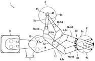
도 1은 본 발명의 실시 형태에 관한 산업용 로봇의 평면도이다.
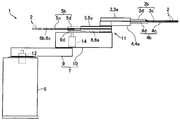
도 2는 도 1에 도시하는 산업용 로봇의 측면도이다.
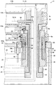
도 3은 도 2에 도시하는 산업용 로봇의 손목부의 단면도이다.
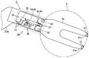
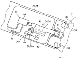
도 4는 도 1에 도시하는 제1 핸드의 선단측 부분의 구성을 설명하기 위한 평면도이다.
도 5는 도 4의 E부의 확대도이다.
도 6은 도 3에 도시하는 제4 중공 회동축의 일부분의 단면도이다.
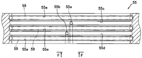
도 7은 도 3에 도시하는 축 지지 부재의 단면도이다.
도 8은 도 7의 F-F 방향에서 축 지지 부재의 일부를 도시하는 도면이다.
도 9는 도 1에 도시하는 산업용 로봇의 동작을 설명하기 위한 평면도이다.
도 10은 도 1에 도시하는 산업용 로봇의 동작을 설명하기 위한 평면도이다.1 is a plan view of an industrial robot according to an embodiment of the present invention.
Fig. 2 is a side view of the industrial robot shown in Fig. 1. Fig.
3 is a sectional view of a wrist portion of the industrial robot shown in Fig.
Fig. 4 is a plan view for explaining the configuration of the tip side portion of the first hand shown in Fig. 1. Fig.
5 is an enlarged view of part E of Fig.
6 is a cross-sectional view of a portion of the fourth hollow rotary shaft shown in Fig.
7 is a sectional view of the shaft supporting member shown in Fig.
8 is a view showing a part of the shaft supporting member in the FF direction in Fig.
Fig. 9 is a plan view for explaining the operation of the industrial robot shown in Fig. 1. Fig.
10 is a plan view for explaining the operation of the industrial robot shown in Fig.
이하, 도면을 참조하면서, 본 발명의 실시 형태를 설명한다.Hereinafter, embodiments of the present invention will be described with reference to the drawings.
(산업용 로봇의 개략 구성)(Rough configuration of industrial robot)
도 1은, 본 발명의 실시 형태에 관한 산업용 로봇(1)의 평면도이다. 도 2는, 도 1에 도시하는 산업용 로봇(1)의 측면도이다. 도 3은, 도 2에 도시하는 산업용 로봇(1)의 손목부(11)의 단면도이다.1 is a plan view of an
본 형태의 산업용 로봇(1)은, 반송 대상물로서의 반도체 웨이퍼(2)를 반송하기 위한 수평 다관절형 로봇이다. 이 산업용 로봇(1)은, 반도체 웨이퍼(2)가 탑재되는 4개의 핸드(3 내지 6)와, 4개의 핸드(3 내지 6)가 회동 가능하게 연결되는 아암(7)과, 아암(7)의 기단측이 회동 가능하게 연결되는 본체부(8)를 구비하고 있다. 이하의 설명에서는, 산업용 로봇(1)을 「로봇(1)」이라고 하고, 반도체 웨이퍼(2)를 「웨이퍼(2)」라고 한다.The
4개의 핸드(3 내지 6)는, 4개의 핸드(3 내지 6)의 기단측이 상하 방향으로 겹치도록 아암(7)의 선단측에 연결되어 있다. 이하, 4개의 핸드(3 내지 6)를 구별하여 나타내는 경우에는, 4개의 핸드(3 내지 6) 중 가장 위에 배치되는 핸드(3)를 「제1 핸드(3)」라고 하고, 위에서부터 두번째에 배치되는 핸드(4)를 「제2 핸드(4)」라고 하고, 위에서부터 세번째에 배치되는 핸드(5)를 「제3 핸드(5)」라고 하고, 가장 밑에 배치되는 핸드(6)를 「제4 핸드(6)」라고 한다. 본 형태에서는, 제1 핸드(3)와 제2 핸드(4)에 의해 제1 핸드 쌍이 구성되어 있고, 제3 핸드(5)와 제4 핸드(6)에 의해 제2 핸드 쌍이 구성되어 있다.The four
본체부(8)는, 대략 사각 기둥형으로 형성되어 있다. 본체부(8)의 내부에는, 아암(7)을 승강시키는 아암 승강 기구(도시 생략)가 수납되어 있다. 아암(7)은, 제1 아암부(9)와 제2 아암부(10)로 구성되어 있다. 제1 아암부(9) 및 제2 아암부(10)는, 중공형으로 형성되어 있다. 제1 아암부(9)의 기단측은, 본체부(8)에 회동 가능하게 연결되어 있다. 제2 아암부(10)의 기단측은, 제1 아암부(9)의 선단측에 회동 가능하게 연결되어 있다. 또한, 로봇(1)은, 본체부(8)에 대하여 제1 아암부(9)를 회동시키는 제1 아암 구동 기구(도시 생략)와, 제1 아암부(9)에 대하여 제2 아암부(10)를 회동시키는 제2 아암 구동 기구(도시 생략)를 구비하고 있다.The
4개의 핸드(3 내지 6)는, 제2 아암부(10)의 선단측에 회동 가능하게 연결되어 있다. 핸드(3 내지 6)와 제2 아암부(10)의 연결부는, 손목부(11)로 되어 있다. 핸드(3 내지 6)는, 아암(7)에 대하여 개별적으로 회동 가능하게 되어 있다. 또한, 핸드(3 내지 6)는, 상하 방향으로 보았을 때 공통의 회동 중심(C1)(도 1 참조)을 중심으로 회동 가능하게 되어 있다. 본체부(8)와 제1 아암부(9)와 제2 아암부(10)와 핸드(3 내지 6)는, 상하 방향에 있어서, 하측으로부터 이 순서대로 배치되어 있다.The four hands (3 to 6) are rotatably connected to the distal end side of the second arm portion (10). The connecting portions of the hands (3 to 6) and the second arm portion (10) are wrist parts (11). The hands (3 to 6) are individually rotatable with respect to the arm (7). Further, the
또한, 로봇(1)은, 제1 핸드(3)를 회동시키는 제1 핸드 구동 기구와, 제2 핸드(4)를 회동시키는 제2 핸드 구동 기구와, 제3 핸드(5)를 회동시키는 제3 핸드 구동 기구와, 제4 핸드(6)를 회동시키는 제4 핸드 구동 기구를 구비하고 있다. 제1 핸드 구동 기구는 모터(12)를 구비하고 있다. 제2 핸드 구동 기구는 모터(13)를 구비하고 있다. 또한, 제3 핸드 구동 기구는 모터(14)를 구비하고, 제4 핸드 구동 기구는 모터(15)를 구비하고 있다.The
모터(12, 13)는, 제1 아암부(9)와 본체부(8)의 연결 부분에 배치되어 있다. 또한, 모터(12)와 모터(13)는 인접하도록 배치되어 있다. 모터(14, 15)는, 제2 아암부(10)의 기단측의 내부에 배치되어 있다. 또한, 모터(14)와 모터(15)는 인접하도록 배치되어 있다. 본 형태에서는, 모터(12, 13)가 제1 아암부(9)의 기단측에 배치되어 있기 때문에, 본체부(8)에 대한 제1 아암부(9)의 회동 시의 관성을 저감하는 것이 가능하게 되어 있다. 또한, 본 형태에서는, 모터(14, 15)가 제2 아암부(10)의 기단측에 배치되어 있기 때문에, 제1 아암부(9)에 대한 제2 아암부(10)의 회동 시의 관성을 저감하는 것이 가능하게 되어 있다.The
또한, 제1 핸드 구동 기구는, 모터(12)의 동력을 제1 핸드(3)에 전달하기 위한 풀리(16) 및 벨트(17)(도 3 참조) 등을 구비하고 있다. 마찬가지로, 제2 핸드 구동 기구는, 모터(13)의 동력을 제2 핸드(4)에 전달하기 위한 풀리(18) 및 벨트(19)(도 3 참조) 등을 구비하고, 제3 핸드 구동 기구는, 모터(14)의 동력을 제3 핸드(5)에 전달하기 위한 풀리(20) 및 벨트(21)(도 3 참조) 등을 구비하고, 제4 핸드 구동 기구는, 모터(15)의 동력을 제4 핸드(6)에 전달하기 위한 풀리(22) 및 벨트(23)(도 3 참조) 등을 구비하고 있다.The first hand driving mechanism has a
(제1 핸드 및 제2 핸드의 구성)(Configuration of first hand and second hand)
도 4는, 도 1에 도시하는 제1 핸드(3)의 선단측 부분의 구성을 설명하기 위한 평면도이다. 도 5는, 도 4의 E부의 확대도이다.4 is a plan view for explaining the configuration of the tip side portion of the
제1 핸드(3) 및 제2 핸드(4)는, 상하 방향으로 보았을 때 굴곡되도록 형성되어 있다. 구체적으로는, 제1 핸드(3) 및 제2 핸드(4)는, 상하 방향으로 보았을 때 소정의 각도로 1회 굴곡되도록 형성되어 있다. 또한, 제1 핸드(3) 및 제2 핸드(4)는, 상하 방향으로 보았을 때 소정의 축선을 대칭축으로 하는 대략 선 대칭으로 형성되어 있다. 즉, 상하 방향으로 보았을 때의 제1 핸드(3)의 굴곡 방향과 제2 핸드(4)의 굴곡 방향은 역방향으로 되어 있다.The
제1 핸드(3)는, 기단측 부분(3a)과 선단측 부분(3b)에 의해 구성되어 있다. 또한, 제1 핸드(3)는, 상하 방향으로 보았을 때 기단측 부분(3a)과 선단측 부분(3b)이 이루는 각도가 둔각으로 되도록 1회 굴곡되어 있고, 전체로서 대략 L 형상(혹은 대략 「く」자 형상)으로 형성되어 있다. 선단측 부분(3b)은, 웨이퍼(2)가 탑재되는 탑재부로서의 웨이퍼 탑재부(3c)와, 웨이퍼 탑재부(3c)를 지지하는 지지부(3d)로 구성되어 있다. 지지부(3d)는, 기단측 부분(3a)과 웨이퍼 탑재부(3c)의 사이에 배치되어 있고, 기단측 부분(3a)과 웨이퍼 탑재부(3c)와 연결되어 있다. 웨이퍼 탑재부(3c)의 선단측은, 두갈래형으로 형성되어 있고, 상하 방향으로 보았을 때의 웨이퍼 탑재부(3c)의 형상은, 대략 Y 형상으로 되어 있다. 웨이퍼 탑재부(3c)는, 평판형으로 형성되어 있다. 기단측 부분(3a) 및 지지부(3d)는, 중공형으로 형성되어 있다. 또한, 기단측 부분(3a)의 내부는, 지지부(3d)의 내부로 통해 있다.The
마찬가지로, 제2 핸드(4)는, 기단측 부분(4a)과 선단측 부분(4b)에 의해 구성되어 있다. 또한, 제2 핸드(4)는, 상하 방향으로 보았을 때 기단측 부분(4a)과 선단측 부분(4b)이 이루는 각도가 둔각으로 되도록 1회 굴곡되어 있고, 전체로서 대략 L 형상(혹은 대략 「く」자 형상)으로 형성되어 있다. 선단측 부분(4b)은, 웨이퍼(2)가 탑재되는 탑재부로서의 웨이퍼 탑재부(4c)와, 웨이퍼 탑재부(4c)를 지지하는 지지부(4d)로 구성되어 있다. 지지부(4d)는, 기단측 부분(4a)과 웨이퍼 탑재부(4c)의 사이에 배치되어 있고, 기단측 부분(4a)과 웨이퍼 탑재부(4c)와 연결되어 있다. 웨이퍼 탑재부(4c)는, 웨이퍼 탑재부(3c)와 동일 형상으로 형성되어 있다. 기단측 부분(4a) 및 지지부(4d)는, 중공형으로 형성되어 있다. 또한, 기단측 부분(4a)의 내부는, 지지부(4d)의 내부로 통해 있다.Similarly, the
제1 핸드(3) 및 제2 핸드(4)는, 웨이퍼(2)를 유지하는 유지부(30)를 구비하고 있다. 유지부(30)는, 도 4에 도시하는 바와 같이, 웨이퍼(2)의 단부면(외주면)이 맞닿는 맞닿음면(31a)을 갖는 단부면 맞닿음 부재(31)와, 웨이퍼(2)의 단부면이 맞닿음면(31a)에 압박되도록 웨이퍼(2)를 누르는 압박 기구(32)를 구비하는 그립형 유지부이다. 단부면 맞닿음 부재(31)는, 두갈래형으로 형성되는 웨이퍼 탑재부(3c, 4c)의 선단측의 상면에 고정되어 있다. 즉, 웨이퍼 탑재부(3c, 4c)에는, 2개의 단부면 맞닿음 부재(31)가 고정되어 있다. 또한, 웨이퍼 탑재부(3c, 4c)의 기단측의 상면의 2군데에는, 웨이퍼(2)가 적재되는 웨이퍼 적재 부재(33)가 고정되어 있고, 웨이퍼(2)는, 단부면 맞닿음 부재(31)와 웨이퍼 적재 부재(33)에 탑재된다.The
압박 기구(32)는, 맞닿음면(31a)을 향하여 웨이퍼(2)의 단부면(외주면)을 누르는 압박부(34)와, 압박부(34)를 구동하는 에어 실린더(35)와, 압박부(34)의 움직임을 검지하는 검지 기구(36)를 구비하고 있다. 압박부(34)는, 웨이퍼(2)의 단부면에 접촉하는 롤러(37)와, 롤러(37)를 회전 가능하게 유지하는 롤러 유지 부재(38)를 구비하고 있다. 검지 기구(36)는, 롤러 유지 부재(38)에 고정되는 검지판(39)과, 2개의 센서(40)를 구비하고 있다.The
롤러 유지 부재(38)는, 가늘고 긴 대략 직육면체형으로 형성되어 있다. 롤러 유지 부재(38)의 기단측은, 에어 실린더(35)의 로드에 고정되어 있다. 롤러(37)는, 롤러 유지 부재(38)의 선단측에 유지되어 있다. 이 롤러(37)는, 상하 방향을 회전의 축 방향으로 하여 회전 가능하게 되어 있다. 압박부(34)는, 도 5의 이점쇄선으로 나타내는 바와 같이 롤러(37)가 웨이퍼(2)의 단부면에 접촉하여 맞닿음면(31a)을 향하여 웨이퍼(2)를 압박하는 압박 위치와, 도 5의 실선으로 나타내는 바와 같이 롤러(37)가 웨이퍼(2)의 단부면으로부터 이격되도록 퇴피하는 퇴피 위치와의 사이에서 직선적으로 이동한다.The roller holding member 38 is formed in a substantially rectangular parallelepiped shape. The base end side of the roller holding member 38 is fixed to the rod of the
센서(40)는, 서로 대향하도록 배치되는 발광 소자와 수광 소자를 갖는 투과형의 광학식 센서이다. 검지판(39)에는, 센서(40)의 발광 소자와 수광 소자의 사이를 차단하기 위한 차광부(39a)가 형성되어 있다. 압박부(34)가 압박 위치에 있을 때에는, 2개의 센서(40) 중 한쪽 센서(40)의 발광 소자와 수광 소자의 사이가 차광부(39a)에 의해 가려지고, 압박부(34)가 퇴피 위치에 있을 때에는, 2개의 센서(40) 중 다른 쪽 센서(40)의 발광 소자와 수광 소자의 사이가 차광부(39a)에 의해 가려진다.The
에어 실린더(35)는, 중공형으로 형성되는 지지부(3d, 4d)의 내부에 배치되어 있다. 롤러 유지 부재(38)는, 롤러 유지 부재(38)의 선단측의 일부분을 제외하고, 지지부(3d, 4d)의 내부에 배치되어 있고, 검지판(39)은, 지지부(3d, 4d)의 내부에 배치되어 있다. 또한, 센서(40)는, 지지부(3d, 4d)의 내부에 배치되어 있다. 즉, 검지 기구(36)는, 지지부(3d, 4d)의 내부에 배치되어 있다. 또한, 도 5에 도시하는 바와 같이, 지지부(3d, 4d)의 내부에는, 직선적으로 이동하는 롤러 유지 부재(38)를 안내하기 위한 가이드 레일(41)이 고정되어 있다. 가이드 레일(41)에는, 롤러 유지 부재(38)의 하면측에 고정되는 가이드 블록(42)이 걸림 결합되어 있다.The
(제3 핸드 및 제4 핸드의 구성)(Configuration of Third Hand and Fourth Hand)
제3 핸드(5) 및 제4 핸드(6)는, 제1 핸드(3) 및 제2 핸드(4)와 마찬가지로, 상하 방향으로 보았을 때 굴곡되도록 형성되어 있다. 즉, 제3 핸드(5) 및 제4 핸드(6)는, 상하 방향으로 보았을 때 소정의 각도로 1회 굴곡되도록 형성되어 있다. 또한, 제3 핸드(5) 및 제4 핸드(6)는, 상하 방향으로 보았을 때 소정의 축선을 대칭축으로 하는 대략 선 대칭으로 형성되어 있고, 상하 방향으로 보았을 때의 제3 핸드(5)의 굴곡 방향과 제4 핸드(5)의 굴곡 방향은 역방향으로 되어 있다.The
제3 핸드(5)는, 기단측 부분(5a)과 선단측 부분(5b)에 의해 구성되어 있다. 또한, 제3 핸드(5)는, 상하 방향으로 보았을 때 기단측 부분(5a)과 선단측 부분(5b)이 이루는 각도가 둔각으로 되도록 1회 굴곡되어 있고, 전체로서 대략 L 형상(혹은 대략 「く」자 형상)으로 형성되어 있다. 선단측 부분(5b)은, 웨이퍼(2)가 탑재되는 웨이퍼 탑재부(5c)와, 웨이퍼 탑재부(5c)를 지지하는 지지부(5d)로 구성되어 있다. 지지부(5d)는, 기단측 부분(5a)과 웨이퍼 탑재부(5c)의 사이에 배치되어 있고, 기단측 부분(5a)과 웨이퍼 탑재부(5c)와 연결되어 있다.The
마찬가지로, 제4 핸드(6)는, 기단측 부분(6a)과 선단측 부분(6b)에 의해 구성되어 있다. 또한, 제4 핸드(6)는, 상하 방향으로 보았을 때 기단측 부분(6a)과 선단측 부분(6b)이 이루는 각도가 둔각으로 되도록 1회 굴곡되어 있고, 전체로서 대략 L 형상(혹은 대략 「く」자 형상)으로 형성되어 있다. 선단측 부분(6b)은, 웨이퍼(2)가 탑재되는 웨이퍼 탑재부(6c)와, 웨이퍼 탑재부(6c)를 지지하는 지지부(6d)로 구성되어 있다. 지지부(6d)는, 기단측 부분(6a)과 웨이퍼 탑재부(6c)의 사이에 배치되어 있고, 기단측 부분(6a)과 웨이퍼 탑재부(6c)와 연결되어 있다.Similarly, the
제3 핸드(5)는, 중공형으로 형성되어 있다. 즉, 기단측 부분(5a), 웨이퍼 탑재부(5c) 및 지지부(5d)는, 기단측 부분(5a)의 내부와 웨이퍼 탑재부(5c)의 내부와 지지부(5d)의 내부가 통하는 중공형으로 형성되어 있다. 마찬가지로, 제4 핸드(6)는, 중공형으로 형성되어 있다. 즉, 기단측 부분(6a), 웨이퍼 탑재부(6c) 및 지지부(6d)는, 기단측 부분(6a)의 내부와 웨이퍼 탑재부(6c)의 내부와 지지부(6d)의 내부가 통하는 중공형으로 형성되어 있다.The
제3 핸드(5) 및 제4 핸드(6)는, 웨이퍼(2)를 유지하는 유지부(45)를 구비하고 있다. 유지부(45)는, 웨이퍼(2)를 흡인하여 유지하는 흡인 구멍(46)(도 1 참조)을 구비하고 있다. 즉, 제3 핸드(5) 및 제4 핸드(6)는, 흡인형 유지부(45)를 구비하고 있고, 웨이퍼(2)를 흡인하여 유지한다. 흡인 구멍(46)은, 웨이퍼 탑재부(5c, 6c)의 선단측에 형성되어 있다. 이 흡인 구멍(46)은, 중공형으로 형성되는 웨이퍼 탑재부(5c, 6c)의 내부로부터 상측으로 관통하도록 형성되어 있다. 웨이퍼 탑재부(5c)에 형성되는 흡인 구멍(46)에는, 후술하는 공기 배관(64)의 일단부가 연결되어 있다. 웨이퍼 탑재부(6c)에 형성되는 흡인 구멍(46)에는, 후술하는 공기 배관(62)의 일단부가 연결되어 있다.The
(손목부의 구성)(Configuration of wrist part)
도 6은, 도 3에 도시하는 중공 회동축(54)의 일부분의 단면도이다. 도 7은, 도 3에 도시하는 축 지지 부재(55)의 단면도이다. 도 8은, 도 7의 F-F 방향에서 축 지지 부재(55)의 일부를 도시하는 도면이다.6 is a sectional view of a part of the
손목부(11)에는, 도 3에 도시하는 바와 같이, 중공형으로 형성되는 제1 중공 회동축으로서의 중공 회동축(51)과, 중공형으로 형성되고 중공 회동축(51)의 외주측에 배치됨과 함께 중공 회동축(51)과 동축 상에 배치되는 제2 중공 회동축으로서의 중공 회동축(52)과, 중공형으로 형성되고 중공 회동축(52)의 외주측에 배치됨과 함께 중공 회동축(51)과 동축 상에 배치되는 제3 중공 회동축으로서의 중공 회동축(53)과, 중공형으로 형성되고 중공 회동축(53)의 외주측에 배치됨과 함께 중공 회동축(51)과 동축 상에 배치되는 제4 중공 회동축으로서의 중공 회동축(54)이 배치되어 있다.As shown in Fig. 3, the
중공 회동축(51 내지 54)은, 가늘고 긴 대략 원통형으로 형성되어 있고, 중공 회동축(51 내지 54)의 축 방향과 상하 방향이 일치하도록 배치되어 있다. 또한, 중공 회동축(51 내지 54)은, 상하 방향으로 보았을 때 공통의 회동 중심(C1)을 중심으로 회동 가능하게 되어 있다. 중공 회동축(51)의 길이는, 중공 회동축(52)의 길이보다 길게 되어 있다. 또한, 중공 회동축(52)의 길이는, 중공 회동축(53)의 길이보다 길게 되어 있고, 중공 회동축(53)의 길이는, 중공 회동축(54)의 길이 보다 길게 되어 있다. 또한, 중공 회동축(51)의 상단부, 중공 회동축(52)의 상단부, 중공 회동축(53)의 상단부 및 중공 회동축(54)의 상단부는, 상측에서부터 이 순서대로 배치되고, 중공 회동축(51)의 하단부, 중공 회동축(52)의 하단부, 중공 회동축(53)의 하단부 및 중공 회동축(54)의 하단부는, 하측에서부터 이 순서대로 배치되어 있다.The
중공 회동축(51)의 상단부에는, 제1 핸드(3)의 기단측 부분(3a)의 하면측이 고정되고, 중공 회동축(52)의 상단부에는, 제2 핸드(4)의 기단측 부분(4a)의 하면측이 고정되고, 중공 회동축(53)의 상단부에는, 제3 핸드(5)의 기단측 부분(5a)의 하면측이 고정되고, 중공 회동축(54)의 상단부에는, 제4 핸드(6)의 기단측 부분(6a)의 하면측이 고정되어 있다. 중공 회동축(51)의 하단부측에는 풀리(16)가 고정되고, 중공 회동축(52)의 하단부측에는 풀리(18)가 고정되고, 중공 회동축(53)의 하단부측에는 풀리(20)가 고정되고, 중공 회동축(54)의 하단부측에는 풀리(22)가 고정되어 있다.The lower end of the base end side portion 3a of the
도 3에 도시하는 바와 같이, 풀리(16, 18, 20, 22)는, 제2 아암부(10)의 선단측의 내부에 배치되어 있다. 즉, 중공 회동축(51 내지 54)의 하단부측 부분은, 제2 아암부(10)의 선단측의 내부에 배치되어 있다. 제2 아암부(10)의 선단측에는, 원통형으로 형성되고 중공 회동축(54)의 외주측에 배치됨과 함께 중공 회동축(51)과 동축 상에 배치되는 축 지지 부재(55)가 고정되어 있다. 축 지지 부재(55)는, 제2 아암부(10)의 상면측에 고정되어 있다.As shown in Fig. 3, the
제1 핸드(3)의 기단측 부분(3a)의 하면측에는, 중공형으로 형성되는 기단측 부분(3a)의 내부가 중공 회동축(51)의 내주측에 통하도록 관통 구멍(3e)이 형성되어 있고, 기단측 부분(3a)의 내부와 중공 회동축(51)의 내주측은, 관통 구멍(3e)을 통하여 연결되어 있다. 제2 핸드(4)의 기단측 부분(4a)에는, 상하 방향으로 관통하는 관통 구멍(4e)이 형성되어 있다. 관통 구멍(4e)에는, 중공 회동축(51)의 상단부측 부분이 삽입 관통되어 있다. 제3 핸드(5)의 기단측 부분(5a)에는, 상하 방향으로 관통하는 관통 구멍(5e)이 형성되어 있다. 관통 구멍(5e)에는, 중공 회동축(51, 52)의 상단부측 부분이 삽입 관통되어 있다. 제4 핸드(6)의 기단측 부분(6a)에는, 상하 방향으로 관통하는 관통 구멍(6e)이 형성되어 있다. 관통 구멍(6e)에는, 중공 회동축(51 내지 53)의 상단부측 부분이 삽입 관통되어 있다.A through
제2 핸드(4)의 관통 구멍(4e)에 삽입 관통되는 중공 회동축(51)의 상단부측 부분에는, 중공 회동축(51)의 직경 방향에서 중공 회동축(51)을 관통하도록 형성됨과 함께 중공 회동축(51)의 둘레 방향을 길이 방향으로 하는 슬릿형 절결부(51a)가 형성되어 있다. 이 절결부(51a)는, 중공 회동축(52)의 상단부보다 상측에 배치되어 있다. 기단측 부분(4a)의 내부에는, 관형으로 형성되는 관형 부재(56)가 고정되어 있다. 관형 부재(56)는, 관형 부재(56)의 축 방향과 중공 회동축(51)의 직경 방향이 일치하도록 배치되어 있고, 관형 부재(56)의 일단부측 부분은, 중공 회동축(51)의 직경 방향에 있어서 절결부(51a)에 삽입 관통되어 있다. 관형 부재(56)의 일단부는, 중공 회동축(51)의 내주면보다 내주측에 배치되어 있다.The upper end portion of the
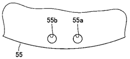
축 지지 부재(55)에는, 축 지지 부재(55)의 하단부면으로부터 축 지지 부재(55)의 내주면에 통하는 2개의 공기 구멍(55a, 55b)이 형성되어 있다. 공기 구멍(55a, 55b)은, 축 지지 부재(55)의 하단부면의 외주측 부분으로부터 상측을 향하여 형성되는 세로 구멍과, 이 세로 구멍의 상단부로부터 축 지지 부재(55)의 내주면을 향하여 형성되는 가로 구멍으로 구성되어 있다. 도 7, 도 8에 도시하는 바와 같이, 공기 구멍(55a)과 공기 구멍(55b)은, 축 유지 부재(55)의 둘레 방향에 있어서 어긋나 있다. 또한, 공기 구멍(55a)의 가로 구멍과 공기 구멍(55b)의 가로 구멍은 상하 방향에 있어서 어긋나 있다.The
도 3에 도시하는 바와 같이, 공기 구멍(55b)의 하단부에는 조인트(57)가 고정되어 있고, 조인트(57)에는 공기 배관(58)의 일단부가 접속되어 있다. 공기 배관(58)의 타단부는, 예를 들어 본체부(8)의 내부에 배치되는 공기의 흡인 수단(도시 생략)에 접속되어 있다. 마찬가지로, 공기 구멍(55a)의 하단부에도 조인트(도시 생략)가 고정되어 있고, 이 조인트에는, 공기 배관(도시 생략)의 일단부가 접속되어 있다. 이 공기 배관의 타단부는, 예를 들어 본체부(8)의 내부에 배치되는 공기의 흡인 수단(도시 생략)에 접속되어 있다.3, a joint 57 is fixed to the lower end of the
도 7에 도시하는 바와 같이, 축 지지 부재(55)의 내주면에는, 공기 구멍(55a)의 가로 구멍이 통하는 원환형의 공기 홈(55c)과, 공기 구멍(55b)의 가로 구멍이 통하는 원환형의 공기 홈(55d)이 형성되어 있다. 또한, 축 지지 부재(55)의 내주면의, 공기 홈(55c)의 상측, 공기 홈(55d)의 하측, 및 공기 홈(55c)과 공기 홈(55d)의 사이에는, O링(59)이 배치되는 원환형의 시일 배치 홈(55e)이 형성되어 있다. 이 O링(59)은, 공기 홈(55c, 55d)으로부터의 공기의 누설을 방지하는 기능을 하고 있다.7, an
중공 회동축(54)에는, 중공 회동축(54)의 외주면으로부터 중공 회동축(54)의 내주면으로 통하는 공기 구멍(54a)이 형성되어 있다. 공기 구멍(54a)은, 상하 방향에 있어서 공기 홈(55c)과 동일한 높이에 배치되어 있고, 중공 회동축(54)의 외주면에 형성되는 공기 구멍(54a)의 일단부는, 공기 홈(55c)에 통해 있다. 도 6에 도시하는 바와 같이, 중공 회동축(54)의 내주면에는, 공기 구멍(54a)의 타단부가 통하는 원환형의 공기 홈(54b)이 형성되어 있다. 또한, 중공 회동축(54)의 내주면의, 공기 홈(54b)의 상측 및 공기 홈(54b)의 하측에는, O링(59)이 배치되는 원환형의 시일 배치 홈(54c)이 형성되어 있다. 이 O링(59)은, 공기 홈(54b)으로부터의 공기의 누설을 방지하는 기능을 하고 있다.The
또한, 중공 회동축(54)에는, 중공 회동축(54)의 외주면으로부터 중공 회동축(54)의 상단부면으로 통하는 공기 구멍(54d)이 형성되어 있다. 공기 구멍(54d)은, 중공 회동축(54)의 외주면으로부터 중공 회동축(54)의 직경 방향의 내측을 향하여 형성되는 가로 구멍과, 이 가로 구멍의 직경 방향 내측 단부로부터 상측을 향하여 형성되는 세로 구멍과, 이 세로 구멍의 상단부로부터 직경 방향의 외측을 향하여 형성되는 가로 구멍과, 이 가로 구멍의 직경 방향 외측 단부로부터 중공 회동축(54)의 상단부면을 향하여 형성되는 세로 구멍으로 구성되어 있다. 도 6에 도시하는 바와 같이, 공기 구멍(54a)과 공기 구멍(54d)은, 회동 중심축(54)의 둘레 방향에 있어서 어긋나 있다.An
공기 구멍(54d)의, 중공 회동축(54)의 외주면으로부터 중공 회동축(54)의 직경 방향의 내측을 향하여 형성되는 가로 구멍은, 상하 방향에 있어서 공기 홈(55d)과 동일한 높이에 배치되어 있고, 중공 회동축(54)의 외주면에 형성되는 이 가로 구멍의 일단부는, 공기 홈(55d)에 통해 있다. 공기 구멍(54d)의 상단부에는, 조인트(61)가 고정되어 있다. 조인트(61)는, 제4 핸드(6)의 기단측 부분(6a)의 내부에 배치되어 있다. 조인트(61)에는, 공기 배관(62)의 일단부가 접속되어 있다. 공기 배관(62)의 타단부는, 웨이퍼 탑재부(6c)에 형성되는 흡인 구멍(46)에 접속되어 있고, 공기 배관(62)은, 제4 핸드(6)의 내부에 깔려 있다.The horizontal hole formed in the
중공 회동축(53)에는, 중공 회동축(53)의 외주면으로부터 중공 회동축(53)의 상단부면으로 통하는 공기 구멍(53a)이 형성되어 있다. 공기 구멍(53a)은, 중공 회동축(53)의 외주면으로부터 중공 회동축(53)의 직경 방향의 내측을 향하여 형성되는 가로 구멍과, 이 가로 구멍의 직경 방향 내측 단부로부터 상측을 향하여 형성되는 세로 구멍과, 이 세로 구멍의 상단부로부터 직경 방향의 외측을 향하여 형성되는 가로 구멍과, 이 가로 구멍의 직경 방향 외측 단부로부터 중공 회동축(53)의 상단부면을 향하여 형성되는 세로 구멍으로 구성되어 있다.The
공기 구멍(53a)의, 중공 회동축(53)의 외주면으로부터 중공 회동축(53)의 직경 방향의 내측을 향하여 형성되는 가로 구멍은, 상하 방향에 있어서 공기 홈(54b)과 동일한 높이에 배치되어 있고, 중공 회동축(53)의 외주면에 형성되는 이 가로 구멍의 일단부는, 공기 홈(54b)에 통해 있다. 공기 구멍(53a)의 상단부에는, 조인트(63)가 고정되어 있다. 조인트(63)는, 제3 핸드(5)의 기단측 부분(5a)의 내부에 배치되어 있다. 조인트(63)에는, 공기 배관(64)의 일단부가 접속되어 있다. 공기 배관(64)의 타단부는, 웨이퍼 탑재부(5c)에 형성되는 흡인 구멍(46)에 접속되어 있고, 공기 배관(64)은, 제3 핸드(5)의 내부에 깔려 있다.The horizontal holes of the
제1 핸드(3)의 지지부(3d)의 내부에 배치되는 에어 실린더(35)용의 2개의 공기 배관(71) 및 지지부(3d)의 내부에 배치되는 검지 기구(36)용 배선(구체적으로는, 센서(40)용 배선)(72)은, 중공 회동축(51)의 내주측을 통과하여 제1 핸드(3)의 기단측 부분(3a)의 내부로 인입되어 있다. 구체적으로는, 본체부(8)로부터 인출되어, 아암(7)의 내부를 통과한 공기 배관(71) 및 배선(72)은, 중공 회동축(51)의 하단부로부터 상단부를 향하여 중공 회동축(51)의 내주측을 통과함과 함께, 관통 구멍(3e)을 통과하여 기단측 부분(3a)의 내부로 인입되어 있다. 또한, 기단측 부분(3a)의 내부로 인입된 공기 배관(71) 및 배선(72)은, 기단측 부분(3a)의 내부를 통과하여 지지부(3d)의 내부까지 깔려 있다. 또한, 2개의 공기 배관(71) 중 한쪽 공기 배관(71)은 급기용 배관이고, 다른 쪽 공기 배관(71)은 배기용 배관이다. 또한, 도 4, 도 5에서는, 배선(72)의 도시를 생략하였다.Two
제2 핸드(4)의 지지부(4d)의 내부에 배치되는 에어 실린더(35)용의 2개의 공기 배관(73) 및 지지부(4d)의 내부에 배치되는 검지 기구(36)용 배선(구체적으로는, 센서(40)용 배선)(74)은, 중공 회동축(51)의 내주측을 통과한 후, 관형 부재(56)를 통과하여 제2 핸드(4)의 기단측 부분(4a)의 내부로 인입되어 있다. 즉, 공기 배관(73) 및 배선(74)은, 중공 회동축(51)의 내주측을 통과한 후, 절결부(51a)를 통과하여 제2 핸드(4)의 기단측 부분(4a)의 내부로 인입되어 있다.Two air piping 73 for the
구체적으로는, 본체부(8)로부터 인출되어, 아암(7)의 내부를 통과한 공기 배관(73) 및 배선(74)은, 중공 회동축(51)의 하단부로부터 상단부측을 향하여 중공 회동축(51)의 내주측을 통과함과 함께, 관형 부재(56)를 통과하여 기단측 부분(4a)의 내부로 인입되어 있다. 또한, 기단측 부분(4a)의 내부로 인입된 공기 배관(73) 및 배선(74)은, 기단측 부분(4a)의 내부를 통과하여 지지부(4d)의 내부까지 깔려 있다. 또한, 2개의 공기 배관(73) 중 한쪽 공기 배관(73)은 급기용 배관이고, 다른 쪽 공기 배관(73)은 배기용 배관이다.Specifically, the air pipe 73 and the wiring 74, which are drawn out from the
상술한 바와 같이, 축 지지 부재(55)에는, 공기 구멍(55a)과, 공기 구멍(55a)의 가로 구멍이 통하는 공기 홈(55c)이 형성되어 있다. 또한, 중공 회동축(54)에는, 공기 홈(55c)과 동일한 높이에 배치되는 공기 구멍(54a)과, 공기 구멍(54a)이 통하는 원환형의 공기 홈(54b)이 형성되어 있다. 또한, 중공 회동축(53)에는, 공기 구멍(53a)이 형성되고, 공기 구멍(53a)의, 중공 회동축(53)의 외주면으로부터 중공 회동축(54)의 직경 방향의 내측을 향하여 형성되는 가로 구멍은, 상하 방향에 있어서 공기 홈(54b)과 동일한 높이에 배치되어 있다. 또한, 공기 구멍(53a)의 상단부에는, 제3 핸드(5)의 기단측 부분(5a)의 내부에 배치되는 조인트(63)가 고정되어 있다.As described above, the
이와 같이, 중공 회동축(53, 54) 및 축 지지 부재(55)에는, 기단측 부분(5a)의 내부로 통하는 공기 구멍(53a, 54a, 55a)이 형성되어 있다. 또한, 공기 구멍(55a)의 하단부에는, 조인트 및 공기 배관을 통하여 공기의 흡인 수단이 접속되고, 공기 구멍(53a)의 상단부는, 조인트(63) 및 공기 배관(64)을 통하여, 웨이퍼 탑재부(5c)에 형성되는 흡인 구멍(46)에 연결되어 있고, 공기 구멍(53a, 54a, 55a), 공기 홈(54b, 55c), 조인트(63) 및 공기 배관(64) 등에 의해, 웨이퍼 탑재부(5c)에 형성되는 흡인 구멍(46)에서 웨이퍼(2)를 흡인하기 위한 공기의 흡인로(통로)가 형성되어 있다.As described above, the hollow
또한, 상술한 바와 같이, 축 지지 부재(55)에는, 공기 구멍(55b)과, 공기 구멍(55b)의 가로 구멍이 통하는 공기 홈(55d)이 형성되어 있다. 또한, 중공 회동축(54)에는, 공기 홈(55d)과 동일한 높이에 배치되는 가로 구멍을 갖는 공기 구멍(54d)이 형성되어 있다. 또한, 공기 구멍(54d)의 상단부에는, 제4 핸드(6)의 기단측 부분(6a)의 내부에 배치되는 조인트(61)가 고정되어 있다. 이와 같이, 중공 회동축(54) 및 축 지지 부재(55)에는, 기단측 부분(6a)의 내부로 통하는 공기 구멍(54d, 55b)이 형성되어 있다. 또한, 공기 구멍(55b)의 하단부에는, 조인트(57) 및 공기 배관(58)을 통하여 공기의 흡인 수단이 접속되고, 공기 구멍(54d)의 상단부는, 조인트(61) 및 공기 배관(62)을 통하여, 웨이퍼 탑재부(6c)에 형성되는 흡인 구멍(46)에 연결되어 있다. 즉, 공기 구멍(54d, 55b), 공기 홈(55d), 조인트(57, 61) 및 공기 배관(58, 62) 등에 의해, 웨이퍼 탑재부(6c)에 형성되는 흡인 구멍(46)에서 웨이퍼(2)를 흡인하기 위한 흡인로(통로)가 형성되어 있다.As described above, the
또한, 본 형태에서는 공기 홈(55c)의 상측, 공기 홈(55d)의 하측, 및 공기 홈(55c)과 공기 홈(55d)의 사이에 배치되는 3개의 O링(59)과, 공기 홈(55c, 55d)에 의해, 회동 중심축(54)과 축 지지 부재(55)의 사이에 로터리 조인트(66)가 형성되어 있다. 또한, 공기 홈(54b)의 상하의 양측에 배치되는 2개의 O링(59)과, 공기 홈(54b)에 의해 회동 중심축(54)과 회동 중심축(53)의 사이에 로터리 조인트(67)가 형성되어 있다.In this embodiment, three O-
(산업용 로봇의 개략 동작)(Rough operation of industrial robot)
도 9, 도 10은, 도 1에 도시하는 로봇(1)의 동작을 설명하기 위한 평면도이다.Figs. 9 and 10 are plan views for explaining the operation of the
본 형태의 로봇(1)은, 반도체 제조 시스템에 내장되어 사용된다. 예를 들어, 로봇(1)은, 반도체 제조 시스템의 입구에 배치되어 있다. 이 경우, 로봇(1)은, 웨이퍼(2)가 소정의 피치로 상하 방향으로 겹치도록 수용되는 카세트(81)와, 웨이퍼(2)가 상하 방향으로 겹치지 않도록 배치되는 처리 장치(82)의 사이에서 웨이퍼(2)를 반송한다.The
구체적으로는, 로봇(1)은, 도 9의 (A), (B)에 도시하는 바와 같이, 처리 장치(82)에서 처리되기 전의 처리 전의 2매의 웨이퍼(2)를 제1 핸드(3) 및 제2 핸드(4)에 의해 카세트(81)로부터 동시에 반출한다. 또한, 로봇(1)은, 2매의 웨이퍼(2)를 제1 핸드(3) 및 제2 핸드(4)에 의해 카세트(81)로부터 반출한 직후에, 도 9의 (C)에 도시하는 바와 같이, 처리 장치(82)에서 처리된 후의 처리 후의 2매의 웨이퍼(2)를 제3 핸드(5) 및 제4 핸드(6)에 의해 카세트(81)로 동시에 반입한다. 제1 핸드(3) 및 제2 핸드(4)가 카세트(81)로부터 웨이퍼(2)를 반출할 때에는, 제1 핸드(3)의 선단측과 제2 핸드(4)의 선단측이 상하 방향으로 겹쳐 있다. 또한, 제3 핸드(5) 및 제4 핸드(6)가 카세트(81)에 웨이퍼(2)를 반입할 때에는, 제3 핸드(5)의 선단측과 제4 핸드(6)의 선단측이 상하 방향으로 겹쳐 있다.Specifically, as shown in Figs. 9 (A) and 9 (B), the
또한, 로봇(1)은, 도 10의 (A)에 도시하는 바와 같이, 처리 장치(82)에서 처리된 후의 처리 후의 2매의 웨이퍼(2)를 제3 핸드(5) 및 제4 핸드(6)에 의해 처리 장치(82)로부터 동시에 반출한다. 또한, 로봇(1)은, 2매의 웨이퍼(2)를 제3 핸드(5) 및 제4 핸드(6)에 의해 처리 장치(82)로부터 반출한 직후에, 도 10의 (B), (C)에 도시하는 바와 같이, 처리 장치(82)에서 처리되기 전의 처리 전의 2매의 웨이퍼(2)를 제1 핸드(3) 및 제2 핸드(4)에 의해 처리 장치(82)로 동시에 반입한다. 제3 핸드(5) 및 제4 핸드(6)가 처리 장치(82)로부터 웨이퍼(2)를 반출할 때에는, 제3 핸드(5)의 선단측과 제4 핸드(6)의 선단측이 상하 방향으로 겹쳐 있지 않다. 제1 핸드(3) 및 제2 핸드(4)가 처리 장치(82)에 웨이퍼(2)를 반입할 때에는, 제1 핸드(3)의 선단측과 제2 핸드(4)의 선단측이 상하 방향으로 겹쳐 있지 않다.10 (A), the
(본 형태의 주된 효과)(Main effect of this embodiment)
이상 설명한 바와 같이, 본 형태의 로봇(1)은, 아암(7)의 선단측에 연결되는 4개의 핸드(3 내지 6)를 구비하고 있고, 4개의 핸드(3 내지 6)는, 아암(7)에 대하여 개별적으로 회동 가능하게 되어 있다. 그로 인해, 본 형태에서는, 상술한 바와 같이, 처리 장치(82)에서 처리되기 전의 처리 전의 2매의 웨이퍼(2)를 제1 핸드(3) 및 제2 핸드(4)를 사용하여 카세트(81)로부터 동시에 반출한 직후에, 처리 장치(82)에서 처리된 후의 처리 후의 2매의 웨이퍼(2)를 제3 핸드(5) 및 제4 핸드(6)를 사용하여 카세트(81)로 동시에 반입할 수 있다. 또한, 본 형태에서는, 상술한 바와 같이, 제3 핸드(5) 및 제4 핸드(6)를 사용하여 처리 후의 2매의 웨이퍼(2)를 처리 장치(82)로부터 동시에 반출한 직후에, 제1 핸드(3) 및 제2 핸드(4)를 사용하여 처리 전의 2매의 웨이퍼(2)를 처리 장치(82)로 동시에 반입할 수 있다. 따라서, 본 형태에서는, 로봇(1)이 내장되어 사용되는 반도체 제조 시스템의 택트 타임을 단축하는 것이 가능하게 된다.As described above, the
여기서, 일반적으로, 카세트(81) 중에서의 웨이퍼(2)의 배치 위치 정밀도는 요구되지 않지만, 처리 장치(82) 중에서의 웨이퍼(2)의 배치 위치 정밀도는 요구된다. 즉, 카세트(81)에 대하여 웨이퍼(2)를 고정밀도로 반입할 필요는 없지만, 처리 장치(82)에 대하여 웨이퍼(2)를 고정밀도로 반입할 필요가 있다. 본 형태에서는, 웨이퍼(2)의 단부면이 맞닿는 맞닿음면(31a)을 갖는 단부면 맞닿음 부재(31)와, 웨이퍼(2)의 단부면이 맞닿음면(31a)에 압박되도록 웨이퍼(2)를 누르는 압박 기구(32)를 갖는 그립형 유지부(30)를 구비한 제1 핸드(3) 및 제2 핸드(4)에 의해, 웨이퍼(2)가 카세트(81)로부터 반출됨과 함께 처리 장치(82)에 반입되고 있다. 그로 인해, 본 형태에서는, 처리 장치(82)에 반입되는 웨이퍼(2)를 제1 핸드(3) 및 제2 핸드(4)에 고정밀도로 탑재하는 것이 가능하게 되고, 그 결과, 처리 장치(82)에 대하여 웨이퍼(2)를 고정밀도로 반입하는 것이 가능하게 된다.In general, positioning accuracy of the
또한, 흡인형 유지부(45)의 경우, 그립형 유지부(30)와 비교하여, 제3 핸드(5) 및 제4 핸드(6)에 탑재되는 웨이퍼(2)의 위치 정밀도는 저하되지만, 그립형 유지부(30)와 같이, 손목부(11)에 있어서 2개의 공기 배관(71, 73) 및 배선(72, 74)을 깔 필요가 없기 때문에, 손목부(11)의 구성을 간소화하는 것이 가능하게 된다. 본 형태에서는, 제3 핸드(5) 및 제4 핸드(6)가 흡인형 유지부(45)를 구비하고 있기 때문에, 제3 핸드(5) 및 제4 핸드(6)가 그립형 유지부(30)를 구비하고 있는 경우와 비교하여, 손목부(11)의 구성을 간소화하는 것이 가능하게 된다. 또한, 본 형태에서는, 흡인 구멍(46)을 갖는 흡인형 유지부(45)를 구비한 제3 핸드(5) 및 제4 핸드(6)에 의해, 웨이퍼(2)가, 처리 장치(82)로부터 반출됨과 함께, 카세트(81)에 반입되고 있지만, 카세트(81)에서는, 웨이퍼(2)의 반입 위치 정밀도가 요구되지 않기 때문에, 카세트(81)에 대한 웨이퍼(2)의 반입 위치에 기인하는 문제는 발생하기 어렵다.In the suction
또한, 본 형태에서는 그립형 유지부(30)를 갖는 제1 핸드(3) 및 제2 핸드(4)가, 흡인형 유지부(45)를 갖는 제3 핸드(5) 및 제4 핸드(6)보다 상측에 배치되어 있고, 중공 회동축(51)의 내주측을 이용하여 공기 배관(71, 73) 및 배선(72, 74)이 깔려 있기 때문에, 제3 핸드(5) 및 제4 핸드(6)가 제1 핸드(3) 및 제2 핸드(4)보다 상측에 배치되어 있는 경우와 비교하여, 손목부(11)의 구성을 간소화하는 것이 가능하게 된다.In this embodiment, the
(다른 실시 형태)(Other Embodiments)
상술한 형태는, 본 발명의 적합한 형태의 일례이기는 하지만, 이것에 한정되는 것은 아니며, 본 발명의 요지를 변경하지 않는 범위에 있어서 여러 가지 변형 실시가 가능하다.Although the above-described embodiment is an example of a suitable form of the present invention, the present invention is not limited thereto, and various modifications may be made without departing from the scope of the present invention.
상술한 형태에서는, 제1 핸드(3) 및 제2 핸드(4)가 그립형 유지부(30)를 구비하고, 제3 핸드(5) 및 제4 핸드(6)가 흡인형 유지부(45)를 구비하고 있지만, 제1 핸드(3) 및 제2 핸드(4)가 흡인형 유지부(45)를 구비하고, 제3 핸드(5) 및 제4 핸드(6)가 그립형 유지부(30)를 구비하고 있어도 된다. 또한, 상술한 형태에서는, 모터(14, 15)는, 제2 아암부(10)의 기단측의 내부에 배치되어 있지만, 모터(14, 15)는, 제1 아암부(9)의 내부에 배치되어도 된다.The
상술한 형태에서는, 아암(7)은, 제1 아암부(9) 및 제2 아암부(10)의 2개의 아암부에 의해 구성되어 있지만, 아암(7)은, 3개 이상의 아암부에 의해 구성되어도 된다. 또한, 상술한 형태에서는, 로봇(1)은, 웨이퍼(2)를 반송하기 위한 로봇이지만, 로봇(1)은, 액정용 유리 기판 등의 다른 반송 대상물을 반송하는 로봇이어도 된다.The
1: 로봇(산업용 로봇)
2: 웨이퍼(반도체 웨이퍼, 반송 대상물)
3: 핸드(제1 핸드, 제1 핸드 쌍의 일부)
3a: 기단측 부분(제1 핸드의 기단측 부분)
3c: 탑재부
3d: 지지부
4: 핸드(제2 핸드, 제1 핸드 쌍의 일부)
4a: 기단측 부분(제2 핸드의 기단측 부분)
4c: 탑재부
4d: 지지부
5: 핸드(제3 핸드, 제2 핸드 쌍의 일부)
5a: 기단측 부분(제3 핸드의 기단측 부분)
6: 핸드(제4 핸드, 제2 핸드 쌍의 일부)
6a: 기단측 부분(제4 핸드의 기단측 부분)
7: 아암
8: 본체부
30: 유지부
31: 단부면 맞닿음 부재
31a: 맞닿음면
32: 압박 기구
34: 압박부
35: 에어 실린더
36: 검지 기구
45: 유지부
46: 흡인 구멍
51: 중공 회동축(제1 중공 회동축)
51a: 절결부
52: 중공 회동축(제2 중공 회동축)
53: 중공 회동축(제3 중공 회동축)
53a: 공기 구멍
54: 중공 회동축(제4 중공 회동축)
54a, 54d: 공기 구멍
71: 공기 배관(제1 핸드의 지지부의 내부에 배치되는 에어 실린더용 공기 배관)
72: 배선(제1 핸드의 지지부의 내부에 배치되는 검지 기구용 배선)
73: 공기 배관(제2 핸드의 지지부의 내부에 배치되는 에어 실린더용 공기 배관)
74: 배선(제2 핸드의 지지부의 내부에 배치되는 검지 기구용 배선)1: Robot (industrial robot)
2: Wafer (semiconductor wafer, conveyance object)
3: Hand (first hand, part of first hand pair)
3a: base-end side portion (base-end side portion of the first hand)
3c:
3d: Support
4: Hand (second hand, part of first hand pair)
4a: proximal side portion (proximal side portion of the second hand)
4c:
4d:
5: Hand (third hand, part of second hand pair)
5a: proximal side portion (proximal side portion of the third hand)
6: Hand (fourth hand, part of second hand pair)
6a: proximal side portion (proximal side portion of the fourth hand)
7:
8:
30:
31: end face abutment member
31a: abutment surface
32:
34:
35: Air cylinder
36: Detection mechanism
45:
46: suction hole
51: hollow shaft (first hollow shaft)
51a:
52: hollow shaft (second hollow shaft)
53: hollow shaft (third hollow shaft)
53a: air hole
54: hollow shaft (fourth hollow shaft)
54a, 54d: air holes
71: air piping (air piping for an air cylinder disposed inside the support portion of the first hand)
72: wiring (detection mechanism wiring arranged inside the support portion of the first hand)
73: air piping (air piping for the air cylinder disposed inside the support portion of the second hand)
74: wiring (detection-use wiring disposed inside the support portion of the second hand)
Claims (4)
4개의 상기 핸드는, 상기 반송 대상물을 유지하는 유지부를 구비하고, 4개의 상기 핸드의 기단측이 상하 방향으로 겹치도록 상기 아암에 연결됨과 함께, 상기 아암에 대하여 개별적으로 회동 가능하게 되어 있고,
4개의 상기 핸드 중 가장 위에 배치되는 상기 핸드와 위에서부터 두번째에 배치되는 상기 핸드를 제1 핸드 쌍이라 하고, 남은 2개의 상기 핸드를 제2 핸드 쌍이라 하면,
상기 제1 핸드 쌍 및 상기 제2 핸드 쌍 중 어느 한쪽을 구성하는 2개의 상기 핸드의 상기 유지부는, 상기 반송 대상물의 단부면이 맞닿는 맞닿음면을 갖는 단부면 맞닿음 부재와, 상기 반송 대상물의 단부면이 상기 맞닿음면에 압박되도록 상기 반송 대상물을 누르는 압박 기구를 구비하고,
상기 제1 핸드 쌍 및 상기 제2 핸드 쌍 중 어느 다른 쪽을 구성하는 2개의 상기 핸드의 상기 유지부는, 상기 반송 대상물을 흡인하여 유지하는 흡인 구멍을 구비하는 것을 특징으로 하는 산업용 로봇.And a main body portion to which the base end side of the arm is rotatably connected. The main body portion includes:
Wherein the four hands are provided with a holding portion for holding the carrying object, the base ends of the four hands are connected to the arm so as to overlap each other in the vertical direction, and are rotatable individually with respect to the arm,
The hand arranged at the top of the four hands and the second hand arranged at the second position from the top are referred to as a first hand pair and the remaining two hands are referred to as a second hand pair,
Wherein the holding portion of the two hands constituting either one of the first hand pair and the second hand pair includes an end face abutment member having an abutment surface abutting the end faces of the carrying object, And a pressing mechanism for pressing the carrying object so that the end face is pressed against the abutment face,
Wherein the holding portion of the two hands constituting the other of the first hand pair and the second hand pair has a suction hole for sucking and holding the carrying object.
중공형으로 형성되고 상기 제1 핸드의 기단측 부분의 하면측이 고정되는 제1 중공 회동축과, 중공형으로 형성되고 상기 제1 중공 회동축의 외주측에, 또한 상기 제1 중공 회동축과 동축 상에 배치됨과 함께 상기 제2 핸드의 기단측 부분의 하면측이 고정되는 제2 중공 회동축과, 중공형으로 형성되고 상기 제2 중공 회동축의 외주측에, 또한 상기 제1 중공 회동축과 동축 상에 배치됨과 함께 상기 제3 핸드의 기단측 부분의 하면측이 고정되는 제3 중공 회동축과, 중공형으로 형성되고 상기 제3 중공 회동축의 외주측에, 또한 상기 제1 중공 회동축과 동축 상에 배치됨과 함께 상기 제4 핸드의 기단측 부분의 하면측이 고정되는 제4 중공 회동축을 구비하고,
상기 제1 핸드 및 상기 제2 핸드의 상기 유지부는, 상기 단부면 맞닿음 부재와 상기 압박 기구를 구비하고,
상기 제3 핸드 및 상기 제4 핸드의 상기 유지부는, 상기 반송 대상물을 흡인하여 유지하는 것을 특징으로 하는 산업용 로봇.The hand according to claim 2, wherein the hand disposed at the top of the four hands is referred to as a first hand, the hand arranged second from the top is referred to as a second hand, Hand is referred to as a hand, and the hand arranged at the bottom is referred to as a fourth hand,
A first hollow rotary shaft formed in a hollow shape and fixed to a lower surface side of a base end side portion of the first hand, and a second hollow rotary shaft formed on the outer peripheral side of the first hollow rotary shaft, A second hollow rotary shaft disposed coaxially and fixed to a lower surface side of the base end side portion of the second hand, and a second hollow rotary shaft formed on the outer peripheral side of the second hollow rotary shaft, And a third hollow pivot shaft disposed coaxially with the third hollow pivot shaft and fixed to a lower surface side of the base end side portion of the third hand, and a second hollow pivot shaft formed on the outer peripheral side of the third hollow pivot shaft, And a fourth hollow rotary shaft disposed coaxially with the coaxial shaft and fixed to the bottom side of the base end side portion of the fourth hand,
Wherein the holding section of the first hand and the second hand includes the end face abutment member and the urging mechanism,
And the holding unit of the third hand and the fourth hand sucks and holds the object to be transported.
상기 제1 핸드의 상기 지지부는, 상기 제1 핸드의 상기 탑재부와 상기 제1 핸드의 기단측 부분을 연결하고 있고,
상기 제2 핸드의 상기 지지부는, 상기 제2 핸드의 상기 탑재부와 상기 제2 핸드의 기단측 부분을 연결하고 있고,
상기 제1 핸드의 기단측 부분 및 상기 지지부와, 상기 제2 핸드의 기단측 부분 및 상기 지지부와, 상기 제3 핸드와, 상기 제4 핸드는, 중공형으로 되어 있고,
상기 제1 핸드의 상기 지지부의 내부 및 상기 제2 핸드의 상기 지지부의 내부에는, 상기 에어 실린더 및 상기 검지 기구가 배치되고,
상기 제1 핸드의 상기 지지부의 내부에 배치되는 상기 에어 실린더용 공기 배관 및 상기 제1 핸드의 상기 지지부의 내부에 배치되는 상기 검지 기구용 배선은, 상기 제1 중공 회동축의 내주측을 통과하여 상기 제1 핸드의 기단측 부분의 내부로 인입되고,
상기 제1 중공 회동축에는, 상기 제1 중공 회동축의 직경 방향으로 관통하도록, 또한 상기 제1 중공 회동축의 둘레 방향을 길이 방향으로 하는 슬릿형 절결부가 형성되고,
상기 절결부는, 상기 제2 중공 회동축의 상단부보다 상측에 배치되고,
상기 제2 핸드의 상기 지지부의 내부에 배치되는 상기 에어 실린더용 공기 배관 및 상기 제2 핸드의 상기 지지부의 내부에 배치되는 상기 검지 기구용 배선은, 상기 제1 중공 회동축의 내주측을 통과한 후, 상기 절결부를 통과하여 상기 제2 핸드의 기단측 부분의 내부로 인입되고,
상기 제3 중공 회동축 및 상기 제4 중공 회동축에는, 상기 제3 핸드의 내부로 통하는 공기 구멍이 형성되고,
상기 제4 중공 회동축에는, 상기 제4 핸드의 내부로 통하는 공기 구멍이 형성되어 있는 것을 특징으로 하는 산업용 로봇.4. The image forming apparatus according to claim 3, wherein the first hand and the second hand comprise a mounting portion on which the conveying object is mounted and a supporting portion for supporting the mounting portion,
The support portion of the first hand connects the mounting portion of the first hand and the base end portion of the first hand,
The support portion of the second hand connects the mounting portion of the second hand and the base end portion of the second hand,
The base end side portion and the support portion of the first hand, the base end side portion and the support portion of the second hand, the third hand, and the fourth hand are hollow,
The air cylinder and the detection mechanism are disposed inside the support portion of the first hand and inside the support portion of the second hand,
The air piping for the air cylinder disposed inside the support portion of the first hand and the detection mechanism wiring disposed inside the support portion of the first hand pass through the inner peripheral side of the first hollow rotary shaft Side portion of the first hand,
Wherein the first hollow rotary shaft is formed with a slit-shaped cutout portion penetrating in the radial direction of the first hollow rotary shaft and the circumferential direction of the first hollow rotary shaft in the longitudinal direction,
Wherein the notch portion is disposed on the upper side of the upper end of the second hollow rotary shaft,
The air piping for the air cylinder disposed inside the support portion of the second hand and the detection mechanism wiring disposed inside the support portion of the second hand are arranged so as to be spaced apart from each other Then passes through the notch portion and enters the base end portion of the second hand,
An air hole communicating with the inside of the third hand is formed in the third hollow rotary shaft and the fourth hollow rotary shaft,
And an air hole communicating with the inside of the fourth hand is formed in the fourth hollow rotary shaft.
Applications Claiming Priority (2)
| Application Number | Priority Date | Filing Date | Title |
|---|---|---|---|
| JP2015256227A JP6649768B2 (en) | 2015-12-28 | 2015-12-28 | Industrial robot |
| JPJP-P-2015-256227 | 2015-12-28 |
Publications (2)
| Publication Number | Publication Date |
|---|---|
| KR20170077807A true KR20170077807A (en) | 2017-07-06 |
| KR102538850B1 KR102538850B1 (en) | 2023-06-01 |
Family
ID=59271594
Family Applications (1)
| Application Number | Title | Priority Date | Filing Date |
|---|---|---|---|
| KR1020160176523A Active KR102538850B1 (en) | 2015-12-28 | 2016-12-22 | Industrial robot |
Country Status (4)
| Country | Link |
|---|---|
| JP (1) | JP6649768B2 (en) |
| KR (1) | KR102538850B1 (en) |
| CN (1) | CN106920765A (en) |
| TW (1) | TWI694906B (en) |
Cited By (2)
| Publication number | Priority date | Publication date | Assignee | Title |
|---|---|---|---|---|
| US20230150120A1 (en) * | 2021-11-17 | 2023-05-18 | Kawasaki Jukogyo Kabushiki Kaisha | Substrate Conveying Robot and Substrate Conveying Robot System |
| CN116262354A (en) * | 2021-12-15 | 2023-06-16 | 日本电产三协株式会社 | Industrial robot and control method of industrial robot |
Families Citing this family (12)
| Publication number | Priority date | Publication date | Assignee | Title |
|---|---|---|---|---|
| CN110944809B (en) * | 2017-08-02 | 2023-04-14 | 株式会社富士 | end effector |
| JP7158877B2 (en) | 2018-03-29 | 2022-10-24 | 日本電産サンキョー株式会社 | INDUSTRIAL ROBOT AND CONTROL METHOD FOR INDUSTRIAL ROBOT |
| JP7313229B2 (en) * | 2019-08-07 | 2023-07-24 | ニデックインスツルメンツ株式会社 | processing system |
| CN111958615A (en) * | 2020-08-19 | 2020-11-20 | 西安奕斯伟硅片技术有限公司 | Assembly and method for conveying wafer |
| JP7530793B2 (en) * | 2020-10-02 | 2024-08-08 | ニデックインスツルメンツ株式会社 | Industrial Robots |
| JP7588999B2 (en) | 2020-10-02 | 2024-11-25 | ニデックインスツルメンツ株式会社 | Industrial robot hand, industrial robot |
| JP7530792B2 (en) * | 2020-10-02 | 2024-08-08 | ニデックインスツルメンツ株式会社 | Industrial robot hand, industrial robot |
| JP7543062B2 (en) | 2020-10-02 | 2024-09-02 | ニデックインスツルメンツ株式会社 | Industrial robot hand, industrial robot |
| JP7562377B2 (en) | 2020-11-09 | 2024-10-07 | ニデックインスツルメンツ株式会社 | How to teach an industrial robot |
| JP7578486B2 (en) * | 2020-12-28 | 2024-11-06 | ニデックインスツルメンツ株式会社 | Industrial Robots |
| JP7730710B2 (en) * | 2021-10-04 | 2025-08-28 | ニデックインスツルメンツ株式会社 | Manufacturing Systems |
| CN116476105A (en) * | 2023-04-28 | 2023-07-25 | 中芯智达半导体科技(上海)有限公司 | Large payload end effector and multi-wrist wafer robot |
Citations (4)
| Publication number | Priority date | Publication date | Assignee | Title |
|---|---|---|---|---|
| JP2008141158A (en) * | 2006-11-29 | 2008-06-19 | Samsung Electronics Co Ltd | Wafer transfer apparatus, wafer transfer method, and computer-readable recording medium |
| WO2010103876A1 (en) * | 2009-03-13 | 2010-09-16 | 川崎重工業株式会社 | Robot provided with end effector, and method for operating the robot |
| KR20110054051A (en) * | 2008-10-17 | 2011-05-24 | 가부시키가이샤 알박 | Conveying device and vacuum device |
| JP2012066342A (en) | 2010-09-24 | 2012-04-05 | Nidec Sankyo Corp | Industrial robot |
Family Cites Families (8)
| Publication number | Priority date | Publication date | Assignee | Title |
|---|---|---|---|---|
| JP2006278629A (en) * | 2005-03-29 | 2006-10-12 | Lintec Corp | Carrying apparatus |
| JP4970128B2 (en) * | 2007-04-27 | 2012-07-04 | 日本電産サンキョー株式会社 | Industrial robot and collective processing device |
| JP4959427B2 (en) * | 2007-06-05 | 2012-06-20 | 日本電産サンキョー株式会社 | Industrial robot |
| KR20100052525A (en) * | 2007-09-10 | 2010-05-19 | 가부시키가이샤 알박 | Substrate transfer robot and vacuum processing apparatus |
| CN102326244B (en) * | 2009-01-11 | 2014-12-17 | 应用材料公司 | Manipulator system, apparatus and method for transferring substrates in electronic device manufacturing |
| JP2013544034A (en) * | 2010-11-10 | 2013-12-09 | ブルックス オートメーション インコーポレイテッド | Double arm robot |
| JP5614417B2 (en) * | 2012-01-05 | 2014-10-29 | 株式会社安川電機 | Transport system |
| US9330951B2 (en) * | 2013-06-05 | 2016-05-03 | Persimmon Technologies, Corp. | Robot and adaptive placement system and method |
-
2015
- 2015-12-28 JP JP2015256227A patent/JP6649768B2/en active Active
-
2016
- 2016-11-11 TW TW105136831A patent/TWI694906B/en active
- 2016-12-14 CN CN201611166866.5A patent/CN106920765A/en not_active Withdrawn
- 2016-12-22 KR KR1020160176523A patent/KR102538850B1/en active Active
Patent Citations (4)
| Publication number | Priority date | Publication date | Assignee | Title |
|---|---|---|---|---|
| JP2008141158A (en) * | 2006-11-29 | 2008-06-19 | Samsung Electronics Co Ltd | Wafer transfer apparatus, wafer transfer method, and computer-readable recording medium |
| KR20110054051A (en) * | 2008-10-17 | 2011-05-24 | 가부시키가이샤 알박 | Conveying device and vacuum device |
| WO2010103876A1 (en) * | 2009-03-13 | 2010-09-16 | 川崎重工業株式会社 | Robot provided with end effector, and method for operating the robot |
| JP2012066342A (en) | 2010-09-24 | 2012-04-05 | Nidec Sankyo Corp | Industrial robot |
Cited By (4)
| Publication number | Priority date | Publication date | Assignee | Title |
|---|---|---|---|---|
| US20230150120A1 (en) * | 2021-11-17 | 2023-05-18 | Kawasaki Jukogyo Kabushiki Kaisha | Substrate Conveying Robot and Substrate Conveying Robot System |
| US12162145B2 (en) * | 2021-11-17 | 2024-12-10 | Kawasaki Jukogyo Kabushiki Kaisha | Substrate conveying robot and substrate conveying robot system |
| CN116262354A (en) * | 2021-12-15 | 2023-06-16 | 日本电产三协株式会社 | Industrial robot and control method of industrial robot |
| KR20230091014A (en) * | 2021-12-15 | 2023-06-22 | 니덱 인스트루먼츠 가부시키가이샤 | Industrial robot and control method of industrial robot |
Also Published As
| Publication number | Publication date |
|---|---|
| TWI694906B (en) | 2020-06-01 |
| TW201722654A (en) | 2017-07-01 |
| JP6649768B2 (en) | 2020-02-19 |
| KR102538850B1 (en) | 2023-06-01 |
| CN106920765A (en) | 2017-07-04 |
| JP2017119326A (en) | 2017-07-06 |
Similar Documents
| Publication | Publication Date | Title |
|---|---|---|
| KR20170077807A (en) | Industrial robot | |
| KR101449881B1 (en) | Industrial robot | |
| KR101680993B1 (en) | Industrial robot | |
| CN101794721B (en) | Alignment apparatus for semiconductor wafer | |
| CN108656123B (en) | Industrial robot | |
| TWI383936B (en) | Substrate exchange device, substrate processing device, and substrate inspection device | |
| CN107251211A (en) | Substrate conveyance manipulator and its method of operation | |
| JP7474325B2 (en) | Wafer transport device and wafer transport method | |
| JP4697211B2 (en) | Conveying robot having substrate alignment mechanism and semiconductor manufacturing apparatus or substrate inspection apparatus having the same | |
| JP2010074093A (en) | Hand for conveying semiconductor wafer | |
| KR102539039B1 (en) | Industrial robot | |
| JP2016107378A (en) | Industrial robot and teaching method of industrial robot | |
| TW201402288A (en) | Robot | |
| CN115039214A (en) | Substrate conveying device and substrate position deviation measuring method | |
| TWI750741B (en) | Industrial robot | |
| CN103328164B (en) | Transportation device, vacuum device | |
| JP2626582B2 (en) | Wafer position measurement unit and wafer alignment unit and method | |
| KR20230082037A (en) | industrial robot | |
| WO2018003578A1 (en) | Alignment device | |
| CN111725117A (en) | Substrate conveying device | |
| JP6630162B2 (en) | Industrial robot | |
| JP2004241484A (en) | Substrate transfer device and method for detecting displacement of transfer device | |
| JP4596144B2 (en) | Wafer transfer method and wafer transfer apparatus | |
| CN118769213A (en) | Robot | |
| KR20230091014A (en) | Industrial robot and control method of industrial robot |
Legal Events
| Date | Code | Title | Description |
|---|---|---|---|
| PA0109 | Patent application |
St.27 status event code: A-0-1-A10-A12-nap-PA0109 |
|
| PG1501 | Laying open of application |
St.27 status event code: A-1-1-Q10-Q12-nap-PG1501 |
|
| A201 | Request for examination | ||
| PA0201 | Request for examination |
St.27 status event code: A-1-2-D10-D11-exm-PA0201 |
|
| PN2301 | Change of applicant |
St.27 status event code: A-3-3-R10-R13-asn-PN2301 St.27 status event code: A-3-3-R10-R11-asn-PN2301 |
|
| E701 | Decision to grant or registration of patent right | ||
| PE0701 | Decision of registration |
St.27 status event code: A-1-2-D10-D22-exm-PE0701 |
|
| PR0701 | Registration of establishment |
St.27 status event code: A-2-4-F10-F11-exm-PR0701 |
|
| PR1002 | Payment of registration fee |
St.27 status event code: A-2-2-U10-U11-oth-PR1002 Fee payment year number: 1 |
|
| PG1601 | Publication of registration |
St.27 status event code: A-4-4-Q10-Q13-nap-PG1601 |
|
| P22-X000 | Classification modified |
St.27 status event code: A-4-4-P10-P22-nap-X000 |