KR20170077875A - Spring structure integrated torque sensor and the structure object thereof - Google Patents
Spring structure integrated torque sensor and the structure object thereof Download PDFInfo
- Publication number
- KR20170077875A KR20170077875A KR1020150187106A KR20150187106A KR20170077875A KR 20170077875 A KR20170077875 A KR 20170077875A KR 1020150187106 A KR1020150187106 A KR 1020150187106A KR 20150187106 A KR20150187106 A KR 20150187106A KR 20170077875 A KR20170077875 A KR 20170077875A
- Authority
- KR
- South Korea
- Prior art keywords
- deformation
- plate
- torque sensor
- spring structure
- torque
- Prior art date
- Legal status (The legal status is an assumption and is not a legal conclusion. Google has not performed a legal analysis and makes no representation as to the accuracy of the status listed.)
- Granted
Links
Images

Classifications
-
- G—PHYSICS
- G01—MEASURING; TESTING
- G01L—MEASURING FORCE, STRESS, TORQUE, WORK, MECHANICAL POWER, MECHANICAL EFFICIENCY, OR FLUID PRESSURE
- G01L3/00—Measuring torque, work, mechanical power, or mechanical efficiency, in general
- G01L3/02—Rotary-transmission dynamometers
- G01L3/04—Rotary-transmission dynamometers wherein the torque-transmitting element comprises a torsionally-flexible shaft
-
- G—PHYSICS
- G01—MEASURING; TESTING
- G01L—MEASURING FORCE, STRESS, TORQUE, WORK, MECHANICAL POWER, MECHANICAL EFFICIENCY, OR FLUID PRESSURE
- G01L1/00—Measuring force or stress, in general
- G01L1/20—Measuring force or stress, in general by measuring variations in ohmic resistance of solid materials or of electrically-conductive fluids; by making use of electrokinetic cells, i.e. liquid-containing cells wherein an electrical potential is produced or varied upon the application of stress
- G01L1/22—Measuring force or stress, in general by measuring variations in ohmic resistance of solid materials or of electrically-conductive fluids; by making use of electrokinetic cells, i.e. liquid-containing cells wherein an electrical potential is produced or varied upon the application of stress using resistance strain gauges
-
- G—PHYSICS
- G01—MEASURING; TESTING
- G01L—MEASURING FORCE, STRESS, TORQUE, WORK, MECHANICAL POWER, MECHANICAL EFFICIENCY, OR FLUID PRESSURE
- G01L3/00—Measuring torque, work, mechanical power, or mechanical efficiency, in general
- G01L3/02—Rotary-transmission dynamometers
- G01L3/04—Rotary-transmission dynamometers wherein the torque-transmitting element comprises a torsionally-flexible shaft
- G01L3/10—Rotary-transmission dynamometers wherein the torque-transmitting element comprises a torsionally-flexible shaft involving electric or magnetic means for indicating
- G01L3/108—Rotary-transmission dynamometers wherein the torque-transmitting element comprises a torsionally-flexible shaft involving electric or magnetic means for indicating involving resistance strain gauges
Landscapes
- Physics & Mathematics (AREA)
- General Physics & Mathematics (AREA)
- Force Measurement Appropriate To Specific Purposes (AREA)
- Manipulator (AREA)
Abstract
본 발명은 스프링 구조 일체형 토크 센서 및 그 구조물에 관한 것으로서, 고정 플레이트, 고정 플레이트와 이격하여 나란히 위치하고 토크에 따라 변형되는 변형 빔을 구비한 변형 감지용 플레이트, 고정 플레이트와 변형 감지용 플레이트를 사선 방향으로 연결하여 토크를 제외한 외력이 변형 빔에 전달되는 것을 방지하는 스프링 구조체, 및 상기 변형 빔에 부착되어 변형을 감지하는 스트레인 게이지를 포함하며, 이를 통해 다른 외력을 제외한 회전 부하 토크 만을 감지할 수 있어 변형 측정의 정확도가 개선된다.[0001] The present invention relates to a spring structure integrated torque sensor and a structure thereof, and more particularly, to a torque sensor having a spring structure and a structure thereof including a fixed plate, a plate for detecting deformation with a deformed beam positioned in parallel to the fixed plate, And a strain gauge attached to the deformed beam and sensing a deformation of the strain gage, wherein only the rotational load torque excluding the other external force can be detected through the spring structure The accuracy of the strain measurement is improved.
Description
본 발명은 토크를 측정하는 센서와 관련한 것으로, 더욱 상세하게는 스프링 구조를 채용하여 회전 부하 토크를 제외한 다른 외력에 영향을 받지 않는 스프링 구조 일체형 토크 센서 및 그 구조물에 관한 것이다.BACKGROUND OF THE INVENTION 1. Field of the Invention The present invention relates to a sensor for measuring torque, and more particularly, to a spring structure integrated torque sensor and its structure that employs a spring structure and is not affected by external forces other than rotational load torque.
산업용 로봇과 같은 기계 장치는 관절 구동을 위한 모듈을 구비하고, 이러한 관절 구동 모듈은 작업 도중 가해지는 토크를 측정하기 위한 토크 센서를 구비한다.A mechanical device such as an industrial robot has a module for joint drive, and the joint drive module has a torque sensor for measuring the torque applied during operation.
그런데 이러한 토크 센서를 감속기의 베어링에 직접 연결하여 적용하면, 해당 베어링에서 완전히 지지하지 못한 외력으로 인하여, 회전 부하 토크 이외의 외력이 토크 센서에서 감지되는 문제가 있다.However, when such a torque sensor is directly connected to the bearing of the speed reducer, there is a problem that an external force other than the rotational load torque is detected by the torque sensor due to an external force which is not fully supported by the bearing.
그리고 이러한 점을 개선하기 위해 추가적으로 커플링 등의 메커니즘과 지지 베어링을 추가하는 경우 관절 구동 모듈의 크기가 커지고 무거워지는 문제가 발생한다.Further, in order to improve this point, there arises a problem that the size of the joint drive module becomes larger and heavier when additional mechanisms such as a coupling and a support bearing are added.
상기와 같은 문제점을 해결하기 위한 본 발명의 목적은, 관절을 구동하는 모듈에 위치한 토크 센서가 스프링 구조체를 채용하여 회전 부하 토크를 제외한 다른 외력에 영향을 받지 않고 토크를 측정하도록 하는 스프링 구조 일체형 토크 센서 및 그 구조물을 제공하기 위한 것이다.SUMMARY OF THE INVENTION [0008] In order to solve the above problems, an object of the present invention is to provide a torque sensor, which is located in a module that drives a joint, employs a spring structure to measure a torque without being influenced by other external forces, Sensor and its structure.
상기와 같은 목적을 달성하기 위한 본 발명의 스프링 구조 일체형 토크 센서는, 고정 플레이트, 상기 고정 플레이트와 이격하여 나란히 위치하고, 토크에 따라 변형되는 변형 빔을 구비한 변형 감지용 플레이트, 상기 고정 플레이트와 상기 변형 감지용 플레이트를 사선 방향으로 연결하여, 토크를 제외한 외력이 상기 변형 빔에 전달되는 것을 방지하는 스프링 구조체, 및 상기 변형 빔에 부착되어 변형을 감지하는 스트레인 게이지를 포함하는 것을 특징으로 한다.According to another aspect of the present invention, there is provided a torque sensor integrated with a spring structure, comprising: a fixed plate; a deformation detecting plate having a deformation beam disposed in parallel to the fixed plate and deformed according to a torque; And a strain gauge attached to the deformed beam to detect a deformation of the strain gage. The strain gage may include a spring structure that connects the deformation detecting plate in an oblique direction to prevent an external force other than a torque from being transmitted to the deformed beam.
본 발명의 스프링 구조 일체형 토크 센서에 있어서, 상기 스프링 구조체는, 상기 고정 플레이트로부터 상기 변형 감지용 플레이트를 사선으로 연결하는 빔과, 상기 변형 감지용 플레이트로부터 상기 고정 플레이트를 사선으로 연결하는 빔이 반복되는 지그재그 형태로 형성된 것을 특징으로 한다.In the spring structure integral torque sensor according to the present invention, the spring structure may include a beam connecting the deformation detection plate with a diagonal line from the fixing plate, and a beam connecting the diaphragm from the deformation detection plate to the diagonal line In a zigzag shape.
본 발명의 스프링 구조 일체형 토크 센서에 있어서, 상기 변형 빔은 상기 변형 감지용 플레이트를 가로지르는 십자(+) 형태로 형성된 것을 특징으로 한다.In the torque sensor integrated with a spring structure according to the present invention, the deformed beam is formed in a cross shape crossing the deformation detecting plate.
본 발명의 스프링 구조 일체형 토크 센서에 있어서, 상기 스트레인 게이지는, 특정 변형 빔의 양면에 서로 대향하여 위치하는 복수의 게이지를 포함하고, 상기 특정 변형 빔과 회전축을 사이에 두고 마주보는 다른 변형 빔의 양면에 서로 대향하여 위치하는 복수의 게이지를 포함하는 것을 특징으로 한다.In the torque sensor integrated with a spring structure of the present invention, the strain gauge includes a plurality of gauges positioned opposite to each other on both sides of a specific deformation beam, and the other deformation beam And a plurality of gauges positioned opposite to each other on both sides.
상기와 같은 목적을 달성하기 위한 본 발명의 스프링 구조 일체형 토크 센서 구조물은, 고정 플레이트, 상기 고정 플레이트와 이격하여 나란히 위치하고, 토크에 따라 변형되고 스트레인 게이지가 부착되는 변형 빔을 구비한 변형 감지용 플레이트, 및 상기 고정 플레이트와 상기 변형 감지용 플레이트를 사선 방향으로 연결하여, 토크를 제외한 외력이 상기 변형 빔에 전달되는 것을 방지하는 스프링 구조체를 포함하는 것을 특징으로 한다.According to an aspect of the present invention, there is provided a torque sensor integrated with a spring structure, comprising: a fixed plate; a deformation detecting plate having a deformation beam which is located in parallel to the fixed plate, And a spring structure connecting the fixing plate and the deformation sensing plate in an oblique direction to prevent an external force from being transmitted to the deformation beam except for a torque.
본 발명의 스프링 구조 일체형 토크 센서 구조물에 있어서, 상기 스프링 구조체는,In the spring structure integral torque sensor structure of the present invention,
상기 고정 플레이트로부터 상기 변형 감지용 플레이트를 사선으로 연결하는 빔과, 상기 변형 감지용 플레이트로부터 상기 고정 플레이트를 사선으로 연결하는 빔이 반복되는 지그재그 형태로 형성된 것을 특징으로 한다.And a zigzag shape in which a beam connecting the deformation detecting plate with a diagonal line from the fixing plate and a beam connecting diagonally the fixing plate from the deformation detecting plate are repeatedly formed.
본 발명의 스프링 구조 일체형 토크 센서 및 그 구조물에 따르면, 회전 방향 부하를 제외한 다른 외력은 스프링 구조체에 의해 감쇠되고, 변형 감지용 플레이트에 구비된 변형 빔은 회전 부하 토크에 의해서만 변형이 발생하므로, 토크를 정밀하게 감지할 수 있다.According to the spring structure integrated torque sensor and the structure of the present invention, the external force other than the rotational direction load is attenuated by the spring structure, and the deformation beam provided on the deformation detecting plate is deformed only by the rotational load torque, Can be precisely detected.
이를 통해 커플링 등 별도의 부품을 채용하지 않고도 회전 부하 토크만을 감지할 수 있어 기구 구성이 간단해지고 경량의 조밀한 관절 구동 모듈을 구성할 수 있다.Therefore, it is possible to detect only the rotational load torque without employing a separate component such as a coupling, so that the mechanism configuration is simplified and a lightweight and compact joint drive module can be constructed.
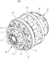
도 1은 본 발명의 일 실시예에 따른 토크 센서가 채용된 관절 구동 모듈을 나타낸 사시도이다.
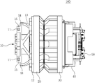
도 2는 본 발명의 일 실시예에 따른 토크 센서가 채용된 관절 구동 모듈을 나타낸 측면도이다.
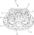
도 3은 본 발명의 일 실시예에 따른 토크 센서를 나타낸 사시도이다.
도 4는 본 발명의 일 실시예에 따른 토크 센서를 나타낸 측면도이다.
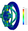
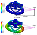
도 5는 본 발명의 일 실시예에 따른 토크 센서가 회전 방향 부하에 따라 변형되는 모습을 나타낸 도면이다.
도 6은 본 발명의 일 실시예에 따른 토크 센서에서 외력이 스프링 구조체에 의해 감쇠되는 모습을 나타낸 도면이다.1 is a perspective view illustrating a joint drive module employing a torque sensor according to an embodiment of the present invention.
2 is a side view of a joint drive module employing a torque sensor according to an embodiment of the present invention.
3 is a perspective view illustrating a torque sensor according to an embodiment of the present invention.
4 is a side view of a torque sensor according to an embodiment of the present invention.
5 is a view showing a torque sensor according to an embodiment of the present invention being deformed in accordance with a rotational direction load.
6 is a view showing a state in which an external force is attenuated by a spring structure in a torque sensor according to an embodiment of the present invention.
하기의 설명에서는 본 발명의 실시예를 이해하는데 필요한 부분만이 설명되며, 그 이외 부분의 설명은 본 발명의 요지를 흩트리지 않도록 생략될 것이라는 것을 유의하여야 한다.In the following description, only parts necessary for understanding the embodiments of the present invention will be described, and the description of other parts will be omitted so as not to obscure the gist of the present invention.
이하에서 설명되는 본 명세서 및 청구범위에 사용된 용어나 단어는 통상적이거나 사전적인 의미로 한정해서 해석되어서는 아니 되며, 발명자는 그 자신의 발명을 가장 최선의 방법으로 설명하기 위해 용어의 개념으로 적절하게 정의할 수 있다는 원칙에 입각하여 본 발명의 기술적 사상에 부합하는 의미와 개념으로 해석되어야만 한다. 따라서 본 명세서에 기재된 실시예와 도면에 도시된 구성은 본 발명의 바람직한 실시예에 불과할 뿐이고, 본 발명의 기술적 사상을 모두 대변하는 것은 아니므로, 본 출원시점에 있어서 이들을 대체할 수 있는 다양한 균등물과 변형예들이 있을 수 있음을 이해하여야 한다.The terms and words used in the present specification and claims should not be construed as limited to ordinary or dictionary meanings and the inventor is not limited to the meaning of the terms in order to describe his invention in the best way. It should be interpreted as meaning and concept consistent with the technical idea of the present invention. Therefore, the embodiments described in the present specification and the configurations shown in the drawings are merely preferred embodiments of the present invention, and are not intended to represent all of the technical ideas of the present invention, so that various equivalents And variations are possible.
본 발명은 토크를 측정하는 센서와 관련한 것이다. 이하, 첨부된 도면을 참조하여 본 발명의 실시예를 보다 상세하게 설명하기로 한다.The present invention relates to a sensor for measuring torque. Hereinafter, embodiments of the present invention will be described in detail with reference to the accompanying drawings.
도 1은 본 발명의 일 실시예에 따른 토크 센서(10)가 채용된 관절 구동 모듈(100)을 나타낸 사시도이고, 도 2는 본 발명의 일 실시예에 따른 토크 센서(10)가 채용된 관절 구동 모듈(100)을 나타낸 측면도이고, 도 3은 본 발명의 일 실시예에 따른 토크 센서(10)를 나타낸 사시도이며, 도 4는 본 발명의 일 실시예에 따른 토크 센서(10)를 나타낸 측면도이다.FIG. 1 is a perspective view showing a
도 1 내지 도 4를 참조하면 본 실시예에 따른 관절 구동 모듈(100)은 토크 센서(10), 감속기(20), 모터(30), 상대 엔코더(40) 및 절대 엔코더(50)를 포함하여 구성된다.1 to 4, a
토크 센서(10)는 토크에 의해 인장 또는 압축되는 변형 빔(15)의 변형률을 측정하는 역할을 하며, 이를 위해 변형 빔(15)에 부착된 스트레인 게이지(strain gage)(11)를 포함한다.The
감속기(20)는 모터(30)의 모터축에 결합되어, 감속비에 따라서 모터축의 회전을 감속시킨다. The
모터(30)는 관절 구동 모듈(100)에 연결되는 관절을 회전시키는데 필요한 회전력을 모터축을 통하여 감속기(20)로 전달한다.The
상대 엔코더(40)는 모터(30)를 사이에 두고 감속기(20)와 대향하는 부분으로 돌출된 모터축에 설치되어, 모터축의 회전량을 검출하여 출력한다. 상대 엔코더(40)는 모터축의 회전량에 따라 단순하게 온/오프의 펄스수로 변환하여 출력하는 엔코더로서, 모터축의 상대적인 위치값을 제공한다. The
절대 엔코더(50)는 모터축의 회전에 따른 절대 위치값을 제공한다.The
이러한 관절 구동 모듈(100)에서 스트레인 게이지(11)를 이용하여 변형 빔(15)에 작용하는 토크를 측정하는 토크 센서(10)는, 스프링 구조체(13)를 이용하여 토크 센서(10)에 작용하는 다른 외력을 감쇠시키고, 회전 부하 토크 만을 검출한다.The
이러한 토크 센서(10)는 스트레인 게이지(11), 고정 플레이트(12), 스프링 구조체(13), 변형 감지용 플레이트(14)를 포함하여 구성된다. 이때 고정 플레이트(12), 스프링 구조체(13) 및 변형 감지용 플레이트(14)는 토크 센서(10) 구조물을 형성한다.The
스트레인 게이지(11)는, 변형 빔(15)에 부착되고, 해당 변형 빔(15)에 토크가 가해져 비틀림모멘트가 발생하면 이에 따른 변형률을 측정한다. 스트레인 게이지(11)는 예를 들어, 박막의 전열체상에 여러 가닥의 세선, 저항박, 반도체 등을 배열한 구조를 포함하고, 스트레인 게이지(11)의 부착 지점에서 토크에 의해 물체의 길이 변화가 발생하면, 이에 따라 변형되는 저항의 저항값의 변화에 따라 물체의 변형률을 측정한다.The
고정 플레이트(12)는 토크 센서(10)를 지지대 역할을 하며, 토크 센서(10)를 감속기(20)의 일측에 결합시킨다.The
변형 감지용 플레이트(14)는 고정 플레이트(12)와 이격하여 나란히 위치하고 스프링 구조체(13)를 통해 연결된다. 변형 감지용 플레이트(14)는 회전 부하 토크에 따라 인장 또는 압축되는 변형 빔(15)을 포함하고, 복수의 변형 빔(15)은 변형 감지용 플레이트(14)를 가로지르는 십자 형태(+)로 형성되며, 해당 변형 빔(15)에는 스트레인 게이지(11)가 부착된다.The
이때 스트레인 게이지(11)는 특정 변형 빔(15)의 양면에 서로 대향하여 위치하는 복수의 게이지를 포함하고, 해당 특정 변형 빔(15)과 회전축을 사이에 두고 마주보는 다른 변형 빔(15)의 양면에 서로 대향하여 위치하는 복수의 게이지를 포함하여, 풀 브릿지(full bridge) 형태로 구성된다.The
스프링 구조체(13)는, 고정 플레이트(12)로부터 변형 감지용 플레이트(14)까지 사선으로 연결된 빔과, 다시 변형 감지용 플레이트(14)로부터 고정 플레이트(12)까지 사선으로 연결된 빔이 반복되는 지그재그 형태로 형성된다.The
이러한 지그재그 형태의 빔을 포함한 스프링 구조체(13)는, 회전 부하 토크를 제외한 외력을 감쇠하여 변형 감지용 플레이트(14)의 변형 빔(15)에 전달되는 것을 방지한다.The
이러한 토크 센서(10)의 특성에 대해서는 도 5 및 도 6을 참조하여 설명한다.The characteristics of the
도 5는 본 발명의 일 실시예에 따른 토크 센서가 회전 방향 부하에 따라 변형되는 모습을 나타낸 도면이다.5 is a view showing a torque sensor according to an embodiment of the present invention being deformed in accordance with a rotational direction load.
도 5를 참조하면, 토크에 따라 변형 빔 부분에 힘이 전달되어, 토크에 따른 변형이 발생함을 확인할 수 있다.Referring to FIG. 5, it can be seen that a force is transmitted to the deformed beam portion according to the torque, and the torque is deformed.
도 6은 본 발명의 일 실시예에 따른 토크 센서에서 외력이 스프링 구조체에 의해 감쇠되는 모습을 나타낸 도면이다.6 is a view showing a state in which an external force is attenuated by a spring structure in a torque sensor according to an embodiment of the present invention.
도 6은 회전 부하 토크가 아닌 다른 외력이 토크 센서에 미치는 영향을 나타낸 결과를 나타내며, 도 6의 상측에는 토크가 아닌 외력을 토크 센서에 가하는 모습이 도시되고, 도 6의 하측에는 해당 외력에 따른 토크 센서의 변형률이 도시된다.6 shows the result of the influence of the external force other than the rotational load torque on the torque sensor. In FIG. 6, an external force other than torque is applied to the torque sensor. The strain of the torque sensor is shown.
도 6의 상측에 도시된 바와 같이 회전 부하 토크가 아닌 외력이 토크 센서에 가해지는 경우에도, 도 6의 하측에 도시된 바와 같이 토크 센서의 변형 빔에는 변형이 발생하지 않음을 확인할 수 있다.6, even when an external force other than the rotational load torque is applied to the torque sensor as shown in the upper side of Fig. 6, it is confirmed that deformation does not occur in the deformation beam of the torque sensor as shown in the lower side of Fig.
즉, 도 5에 도시된 바와 같이 본 발명의 토크 센서의 변형 빔은 회전 부하 토크에 의해 변형되지만, 도 6에 도시된 바와 같이 토크가 아닌 다른 외력에 의해서는 변형이 발생하지 않음을 확인할 수 있다.That is, as shown in FIG. 5, the deformed beam of the torque sensor of the present invention is deformed by the rotational load torque, but it can be confirmed that no deformation occurs due to an external force other than torque as shown in FIG. 6 .
이에 따라 회전 부하 토크가 아닌 외력은 토크 센서의 스프링 구조체에 의해 감쇠되어 변형 빔에 영향을 미치지 않음을 알 수 있다.Thus, it can be seen that the external force, which is not the rotational load torque, is attenuated by the spring structure of the torque sensor and does not affect the deformation beam.
한편, 본 명세서와 도면에 개시된 실시예들은 이해를 돕기 위해 특정 예를 제시한 것에 지나지 않으며, 본 발명의 범위를 한정하고자 하는 것은 아니다. 여기에 개시된 실시예들 이외에도 본 발명의 기술적 사상에 바탕을 둔 다른 변형예들이 실시 가능하다는 것은, 본 발명이 속하는 기술분야에서 통상의 지식을 가진 자에게는 자명한 것이다. 또한, 본 명세서와 도면에서 특정 용어들이 사용되었으나, 이는 단지 본 발명의 기술 내용을 쉽게 설명하고 발명의 이해를 돕기 위한 일반적인 의미에서 사용된 것이지, 본 발명의 범위를 한정하고자 하는 것은 아니다.It should be noted that the embodiments disclosed in the present specification and drawings are only illustrative of specific examples for the purpose of understanding, and are not intended to limit the scope of the present invention. It will be apparent to those skilled in the art that other modifications based on the technical idea of the present invention are possible in addition to the embodiments disclosed herein. Furthermore, although specific terms are used in this specification and the drawings, they are used in a generic sense only to facilitate the description of the invention and to facilitate understanding of the invention, and are not intended to limit the scope of the invention.
10: 토크 센서
11: 스트레인 게이지
12: 고정 플레이트
13: 스프링 구조체
14: 변형 감지용 플레이트
15: 변형 빔
20: 감속기
30: 모터
40: 상대 엔코더
50: 절대 엔코더
100: 관절 구동 모듈10: Torque sensor 11: Strain gauge
12: Fixing plate 13: Spring structure
14: Plate for deformation detection 15: Deformation beam
20: Reducer 30: Motor
40: Relative encoder 50: Absolute encoder
100: Joint drive module
Claims (6)
상기 고정 플레이트와 이격하여 나란히 위치하고, 토크에 따라 변형되는 변형 빔을 구비한 변형 감지용 플레이트;
상기 고정 플레이트와 상기 변형 감지용 플레이트를 사선 방향으로 연결하여, 토크를 제외한 외력이 상기 변형 빔에 전달되는 것을 방지하는 스프링 구조체; 및
상기 변형 빔에 부착되어 변형을 감지하는 스트레인 게이지;
를 포함하는 것을 특징으로 하는 스프링 구조 일체형 토크 센서.A fixing plate;
A deformation detecting plate having a deformation beam positioned side by side apart from the fixed plate and deformed according to a torque;
A spring structure connecting the fixing plate and the deformation sensing plate in an oblique direction to prevent an external force from being transmitted to the deformation beam except a torque; And
A strain gauge attached to the deformation beam to sense deformation;
Wherein the torque sensor comprises a spring.
상기 스프링 구조체는,
상기 고정 플레이트로부터 상기 변형 감지용 플레이트를 사선으로 연결하는 빔과, 상기 변형 감지용 플레이트로부터 상기 고정 플레이트를 사선으로 연결하는 빔이 반복되는 지그재그 형태로 형성된 것을 특징으로 하는 스프링 구조 일체형 토크 센서.The method according to claim 1,
Wherein the spring structure comprises:
And a beam connecting diagonally the deformation detecting plate from the fixing plate and a beam connecting diagonally the fixing plate from the deformation detecting plate are repeatedly formed in a zigzag shape.
상기 변형 빔은 상기 변형 감지용 플레이트를 가로지르는 십자(+) 형태로 형성된 것을 특징으로 하는 스프링 구조 일체형 토크 센서.The method according to claim 1,
Wherein the deformation beam is formed in a cross shape crossing the deformation detection plate.
상기 스트레인 게이지는,
특정 변형 빔의 양면에 서로 대향하여 위치하는 복수의 게이지를 포함하고, 상기 특정 변형 빔과 회전축을 사이에 두고 마주보는 다른 변형 빔의 양면에 서로 대향하여 위치하는 복수의 게이지를 포함하는 것을 특징으로 하는 스프링 구조 일체형 토크 센서.The method of claim 3,
Wherein the strain gauge comprises:
And a plurality of gauges including a plurality of gauges positioned opposite to each other on both sides of the specific deformation beam and positioned opposite to each other on opposite sides of the other deformation beam facing the specific deformation beam and the rotation axis. Integrated torque sensor with spring structure.
상기 고정 플레이트와 이격하여 나란히 위치하고, 토크에 따라 변형되고 스트레인 게이지가 부착되는 변형 빔을 구비한 변형 감지용 플레이트; 및
상기 고정 플레이트와 상기 변형 감지용 플레이트를 사선 방향으로 연결하여, 토크를 제외한 외력이 상기 변형 빔에 전달되는 것을 방지하는 스프링 구조체;
를 포함하는 것을 특징으로 하는 스프링 구조 일체형 토크 센서 구조물.A fixing plate;
A deformation detecting plate having a deformation beam positioned side by side apart from the fixed plate and deformed according to a torque and to which a strain gauge is attached; And
A spring structure connecting the fixing plate and the deformation sensing plate in an oblique direction to prevent an external force from being transmitted to the deformation beam except a torque;
Wherein the torque sensor structure comprises a spring structure.
상기 스프링 구조체는,
상기 고정 플레이트로부터 상기 변형 감지용 플레이트를 사선으로 연결하는 빔과, 상기 변형 감지용 플레이트로부터 상기 고정 플레이트를 사선으로 연결하는 빔이 반복되는 지그재그 형태로 형성된 것을 특징으로 하는 스프링 구조 일체형 토크 센서 구조물.6. The method of claim 5,
Wherein the spring structure comprises:
Wherein a beam connecting the deformation detecting plate to the deformation detecting plate and a beam connecting the diaphragm from the deformation detecting plate to the diaphragm are repeatedly formed in a zigzag shape.
Priority Applications (1)
| Application Number | Priority Date | Filing Date | Title |
|---|---|---|---|
| KR1020150187106A KR102129890B1 (en) | 2015-12-28 | 2015-12-28 | Spring structure integrated torque sensor and the structure object thereof |
Applications Claiming Priority (1)
| Application Number | Priority Date | Filing Date | Title |
|---|---|---|---|
| KR1020150187106A KR102129890B1 (en) | 2015-12-28 | 2015-12-28 | Spring structure integrated torque sensor and the structure object thereof |
Publications (2)
| Publication Number | Publication Date |
|---|---|
| KR20170077875A true KR20170077875A (en) | 2017-07-07 |
| KR102129890B1 KR102129890B1 (en) | 2020-07-06 |
Family
ID=59353881
Family Applications (1)
| Application Number | Title | Priority Date | Filing Date |
|---|---|---|---|
| KR1020150187106A Expired - Fee Related KR102129890B1 (en) | 2015-12-28 | 2015-12-28 | Spring structure integrated torque sensor and the structure object thereof |
Country Status (1)
| Country | Link |
|---|---|
| KR (1) | KR102129890B1 (en) |
Cited By (2)
| Publication number | Priority date | Publication date | Assignee | Title |
|---|---|---|---|---|
| CN112362200A (en) * | 2020-11-23 | 2021-02-12 | 广西大学 | Cross-shaped double-straight-beam capacitive torque sensor |
| CN116124073A (en) * | 2023-04-20 | 2023-05-16 | 江苏神铸智能科技有限公司 | A flatness testing machine for aluminum alloy plates that can adapt to different thicknesses |
Citations (6)
| Publication number | Priority date | Publication date | Assignee | Title |
|---|---|---|---|---|
| KR20050001828A (en) * | 2003-06-26 | 2005-01-07 | 주식회사 만도 | Non contacting torque sensor |
| KR20070084807A (en) * | 2006-02-22 | 2007-08-27 | 경상대학교산학협력단 | Robot Cuff 6-Axis Force / Moment Sensor |
| JP2012521547A (en) * | 2009-03-25 | 2012-09-13 | ホッティンゲル・バルドヴィン・メステクニーク・ゲゼルシヤフト・ミト・ベシュレンクテル・ハフツング | Torque sensor |
| KR101280899B1 (en) * | 2011-12-27 | 2013-07-05 | 전자부품연구원 | 1-axis torque sensor for robot joint |
| KR101460031B1 (en) * | 2013-12-23 | 2014-11-12 | 전자부품연구원 | 1-axis torque sensor and 1-axis joint module using the same |
| KR101509578B1 (en) | 2013-11-29 | 2015-04-08 | 전자부품연구원 | Apparatus and method for calculating absolute position of driving shaft |
-
2015
- 2015-12-28 KR KR1020150187106A patent/KR102129890B1/en not_active Expired - Fee Related
Patent Citations (6)
| Publication number | Priority date | Publication date | Assignee | Title |
|---|---|---|---|---|
| KR20050001828A (en) * | 2003-06-26 | 2005-01-07 | 주식회사 만도 | Non contacting torque sensor |
| KR20070084807A (en) * | 2006-02-22 | 2007-08-27 | 경상대학교산학협력단 | Robot Cuff 6-Axis Force / Moment Sensor |
| JP2012521547A (en) * | 2009-03-25 | 2012-09-13 | ホッティンゲル・バルドヴィン・メステクニーク・ゲゼルシヤフト・ミト・ベシュレンクテル・ハフツング | Torque sensor |
| KR101280899B1 (en) * | 2011-12-27 | 2013-07-05 | 전자부품연구원 | 1-axis torque sensor for robot joint |
| KR101509578B1 (en) | 2013-11-29 | 2015-04-08 | 전자부품연구원 | Apparatus and method for calculating absolute position of driving shaft |
| KR101460031B1 (en) * | 2013-12-23 | 2014-11-12 | 전자부품연구원 | 1-axis torque sensor and 1-axis joint module using the same |
Non-Patent Citations (1)
| Title |
|---|
| <논문> * |
Cited By (2)
| Publication number | Priority date | Publication date | Assignee | Title |
|---|---|---|---|---|
| CN112362200A (en) * | 2020-11-23 | 2021-02-12 | 广西大学 | Cross-shaped double-straight-beam capacitive torque sensor |
| CN116124073A (en) * | 2023-04-20 | 2023-05-16 | 江苏神铸智能科技有限公司 | A flatness testing machine for aluminum alloy plates that can adapt to different thicknesses |
Also Published As
| Publication number | Publication date |
|---|---|
| KR102129890B1 (en) | 2020-07-06 |
Similar Documents
| Publication | Publication Date | Title |
|---|---|---|
| KR102230369B1 (en) | Torque sensor device and method for measuring torque | |
| US7743672B2 (en) | Multiple axis load cell controller | |
| JP6135408B2 (en) | Torque sensor, driving device, and robot | |
| KR101141719B1 (en) | Device and Method of Calibrating Torque Sensor for Robot Joint | |
| US20120180574A1 (en) | Load cell for monitoring torsion and having overload protection | |
| JP5640905B2 (en) | Straining body and apparatus including the same | |
| CN103359279A (en) | Piloting device for piloting aircraft having protected force sensor | |
| KR102003906B1 (en) | Robot articulation unit having joint torque sensor | |
| US10421532B2 (en) | Connecting rod for a flight control surface actuation system | |
| CN109959359A (en) | Strain transducer, multi-axis force transducer and robot | |
| JP2007500361A (en) | Improved deflection system for strain-based instruments | |
| ES2973245T3 (en) | Procedure to correct a misalignment of at least one axle train | |
| CN103743508B (en) | Torsional moment test macro and torque sensor device thereof | |
| JP6734372B2 (en) | Force measuring device | |
| KR20170077875A (en) | Spring structure integrated torque sensor and the structure object thereof | |
| US8569988B2 (en) | Elastic rotary actuator, particularly for robotic applications, and method for controlling the same | |
| KR102163960B1 (en) | Flexible joint module | |
| KR102704645B1 (en) | In particular, actuator systems for vehicles | |
| WO2019116817A1 (en) | Load sensor, and electric brake | |
| JPH11230838A (en) | Torque meter | |
| JP2018036097A (en) | Angle position detector | |
| JP2010139395A (en) | Torque sensor and steering equipped with the same | |
| ES2672357T3 (en) | Car brake test bench | |
| KR100737168B1 (en) | Actuator integrated torque sensor for joint torque measurement | |
| KR102018312B1 (en) | Actuating device for measuring force |
Legal Events
| Date | Code | Title | Description |
|---|---|---|---|
| PA0109 | Patent application |
St.27 status event code: A-0-1-A10-A12-nap-PA0109 |
|
| PG1501 | Laying open of application |
St.27 status event code: A-1-1-Q10-Q12-nap-PG1501 |
|
| P22-X000 | Classification modified |
St.27 status event code: A-2-2-P10-P22-nap-X000 |
|
| A201 | Request for examination | ||
| PA0201 | Request for examination |
St.27 status event code: A-1-2-D10-D11-exm-PA0201 |
|
| D13-X000 | Search requested |
St.27 status event code: A-1-2-D10-D13-srh-X000 |
|
| D14-X000 | Search report completed |
St.27 status event code: A-1-2-D10-D14-srh-X000 |
|
| E902 | Notification of reason for refusal | ||
| PE0902 | Notice of grounds for rejection |
St.27 status event code: A-1-2-D10-D21-exm-PE0902 |
|
| P11-X000 | Amendment of application requested |
St.27 status event code: A-2-2-P10-P11-nap-X000 |
|
| P13-X000 | Application amended |
St.27 status event code: A-2-2-P10-P13-nap-X000 |
|
| E701 | Decision to grant or registration of patent right | ||
| PE0701 | Decision of registration |
St.27 status event code: A-1-2-D10-D22-exm-PE0701 |
|
| GRNT | Written decision to grant | ||
| PR0701 | Registration of establishment |
St.27 status event code: A-2-4-F10-F11-exm-PR0701 |
|
| PR1002 | Payment of registration fee |
St.27 status event code: A-2-2-U10-U11-oth-PR1002 Fee payment year number: 1 |
|
| PG1601 | Publication of registration |
St.27 status event code: A-4-4-Q10-Q13-nap-PG1601 |
|
| R18-X000 | Changes to party contact information recorded |
St.27 status event code: A-5-5-R10-R18-oth-X000 |
|
| PN2301 | Change of applicant |
St.27 status event code: A-5-5-R10-R13-asn-PN2301 St.27 status event code: A-5-5-R10-R11-asn-PN2301 |
|
| PN2301 | Change of applicant |
St.27 status event code: A-5-5-R10-R13-asn-PN2301 St.27 status event code: A-5-5-R10-R11-asn-PN2301 |
|
| PR1001 | Payment of annual fee |
St.27 status event code: A-4-4-U10-U11-oth-PR1001 Fee payment year number: 4 |
|
| PR1001 | Payment of annual fee |
St.27 status event code: A-4-4-U10-U11-oth-PR1001 Fee payment year number: 5 |
|
| PC1903 | Unpaid annual fee |
St.27 status event code: A-4-4-U10-U13-oth-PC1903 Not in force date: 20250630 Payment event data comment text: Termination Category : DEFAULT_OF_REGISTRATION_FEE |
|
| H13 | Ip right lapsed |
Free format text: ST27 STATUS EVENT CODE: N-4-6-H10-H13-OTH-PC1903 (AS PROVIDED BY THE NATIONAL OFFICE); TERMINATION CATEGORY : DEFAULT_OF_REGISTRATION_FEE Effective date: 20250630 |
|
| PC1903 | Unpaid annual fee |
St.27 status event code: N-4-6-H10-H13-oth-PC1903 Ip right cessation event data comment text: Termination Category : DEFAULT_OF_REGISTRATION_FEE Not in force date: 20250630 |