KR20170113402A - Vane compressor - Google Patents
Vane compressor Download PDFInfo
- Publication number
- KR20170113402A KR20170113402A KR1020170040732A KR20170040732A KR20170113402A KR 20170113402 A KR20170113402 A KR 20170113402A KR 1020170040732 A KR1020170040732 A KR 1020170040732A KR 20170040732 A KR20170040732 A KR 20170040732A KR 20170113402 A KR20170113402 A KR 20170113402A
- Authority
- KR
- South Korea
- Prior art keywords
- shaft
- suction port
- communication passage
- suction
- cylinder chamber
- Prior art date
- Legal status (The legal status is an assumption and is not a legal conclusion. Google has not performed a legal analysis and makes no representation as to the accuracy of the status listed.)
- Granted
Links
Images


Classifications
-
- F—MECHANICAL ENGINEERING; LIGHTING; HEATING; WEAPONS; BLASTING
- F04—POSITIVE - DISPLACEMENT MACHINES FOR LIQUIDS; PUMPS FOR LIQUIDS OR ELASTIC FLUIDS
- F04C—ROTARY-PISTON, OR OSCILLATING-PISTON, POSITIVE-DISPLACEMENT MACHINES FOR LIQUIDS; ROTARY-PISTON, OR OSCILLATING-PISTON, POSITIVE-DISPLACEMENT PUMPS
- F04C18/00—Rotary-piston pumps specially adapted for elastic fluids
- F04C18/30—Rotary-piston pumps specially adapted for elastic fluids having the characteristics covered by two or more of groups F04C18/02, F04C18/08, F04C18/22, F04C18/24, F04C18/48, or having the characteristics covered by one of these groups together with some other type of movement between co-operating members
- F04C18/34—Rotary-piston pumps specially adapted for elastic fluids having the characteristics covered by two or more of groups F04C18/02, F04C18/08, F04C18/22, F04C18/24, F04C18/48, or having the characteristics covered by one of these groups together with some other type of movement between co-operating members having the movement defined in group F04C18/08 or F04C18/22 and relative reciprocation between the co-operating members
- F04C18/344—Rotary-piston pumps specially adapted for elastic fluids having the characteristics covered by two or more of groups F04C18/02, F04C18/08, F04C18/22, F04C18/24, F04C18/48, or having the characteristics covered by one of these groups together with some other type of movement between co-operating members having the movement defined in group F04C18/08 or F04C18/22 and relative reciprocation between the co-operating members with vanes reciprocating with respect to the inner member
- F04C18/3446—Rotary-piston pumps specially adapted for elastic fluids having the characteristics covered by two or more of groups F04C18/02, F04C18/08, F04C18/22, F04C18/24, F04C18/48, or having the characteristics covered by one of these groups together with some other type of movement between co-operating members having the movement defined in group F04C18/08 or F04C18/22 and relative reciprocation between the co-operating members with vanes reciprocating with respect to the inner member the inner and outer member being in contact along more than one line or surface
-
- F—MECHANICAL ENGINEERING; LIGHTING; HEATING; WEAPONS; BLASTING
- F04—POSITIVE - DISPLACEMENT MACHINES FOR LIQUIDS; PUMPS FOR LIQUIDS OR ELASTIC FLUIDS
- F04B—POSITIVE-DISPLACEMENT MACHINES FOR LIQUIDS; PUMPS
- F04B39/00—Component parts, details, or accessories, of pumps or pumping systems specially adapted for elastic fluids, not otherwise provided for in, or of interest apart from, groups F04B25/00 - F04B37/00
- F04B39/10—Adaptations or arrangements of distribution members
- F04B39/1073—Adaptations or arrangements of distribution members the members being reed valves
-
- F—MECHANICAL ENGINEERING; LIGHTING; HEATING; WEAPONS; BLASTING
- F04—POSITIVE - DISPLACEMENT MACHINES FOR LIQUIDS; PUMPS FOR LIQUIDS OR ELASTIC FLUIDS
- F04C—ROTARY-PISTON, OR OSCILLATING-PISTON, POSITIVE-DISPLACEMENT MACHINES FOR LIQUIDS; ROTARY-PISTON, OR OSCILLATING-PISTON, POSITIVE-DISPLACEMENT PUMPS
- F04C27/00—Sealing arrangements in rotary-piston pumps specially adapted for elastic fluids
- F04C27/008—Sealing arrangements in rotary-piston pumps specially adapted for elastic fluids for other than working fluid, i.e. the sealing arrangements are not between working chambers of the machine
- F04C27/009—Shaft sealings specially adapted for pumps
-
- F—MECHANICAL ENGINEERING; LIGHTING; HEATING; WEAPONS; BLASTING
- F04—POSITIVE - DISPLACEMENT MACHINES FOR LIQUIDS; PUMPS FOR LIQUIDS OR ELASTIC FLUIDS
- F04C—ROTARY-PISTON, OR OSCILLATING-PISTON, POSITIVE-DISPLACEMENT MACHINES FOR LIQUIDS; ROTARY-PISTON, OR OSCILLATING-PISTON, POSITIVE-DISPLACEMENT PUMPS
- F04C29/00—Component parts, details or accessories of pumps or pumping installations, not provided for in groups F04C18/00 - F04C28/00
- F04C29/04—Heating; Cooling; Heat insulation
-
- F—MECHANICAL ENGINEERING; LIGHTING; HEATING; WEAPONS; BLASTING
- F04—POSITIVE - DISPLACEMENT MACHINES FOR LIQUIDS; PUMPS FOR LIQUIDS OR ELASTIC FLUIDS
- F04C—ROTARY-PISTON, OR OSCILLATING-PISTON, POSITIVE-DISPLACEMENT MACHINES FOR LIQUIDS; ROTARY-PISTON, OR OSCILLATING-PISTON, POSITIVE-DISPLACEMENT PUMPS
- F04C29/00—Component parts, details or accessories of pumps or pumping installations, not provided for in groups F04C18/00 - F04C28/00
- F04C29/12—Arrangements for admission or discharge of the working fluid, e.g. constructional features of the inlet or outlet
- F04C29/124—Arrangements for admission or discharge of the working fluid, e.g. constructional features of the inlet or outlet with inlet and outlet valves specially adapted for rotary or oscillating piston pumps
- F04C29/126—Arrangements for admission or discharge of the working fluid, e.g. constructional features of the inlet or outlet with inlet and outlet valves specially adapted for rotary or oscillating piston pumps of the non-return type
- F04C29/128—Arrangements for admission or discharge of the working fluid, e.g. constructional features of the inlet or outlet with inlet and outlet valves specially adapted for rotary or oscillating piston pumps of the non-return type of the elastic type, e.g. reed valves
Landscapes
- Engineering & Computer Science (AREA)
- Mechanical Engineering (AREA)
- General Engineering & Computer Science (AREA)
- Rotary Pumps (AREA)
- Applications Or Details Of Rotary Compressors (AREA)
Abstract
(과제) 흡입실 내의 냉매가 축봉 장치를 향하여 보다 흐르기 쉽게 하는 것이 가능한 베인형 압축기를 얻는다.
(해결 수단) 축봉 장치는, 제1 축 구멍(12h)과 샤프트(15)의 사이에 설치된다. 제1 벽부에는, 흡입 통로와 제1 축 구멍(12h)을 연통시키는 제1 연통 통로(24) 및 제2 연통 통로(25)가 관통 형성된다. 제1 흡입구(22)와 제2 흡입구(23) 중 적어도 한쪽은, 흡입 통로의 도중에 개구하고 있다. 제1 연통 통로(24)는, 제2 흡입구(23)보다도 흡입 포트(11a)에 가까운 측에서 개구하고, 제2 연통 통로(25)는, 제1 흡입구(22)보다도 흡입 포트(11a)로부터 먼 측에서 개구하고 있다.[PROBLEMS] To provide a canopy-type compressor capable of allowing a refrigerant in a suction chamber to flow more easily toward a shaft end device.
[MEANS FOR SOLVING PROBLEMS] A shaft end device is provided between a first shaft hole (12h) and a shaft (15). A first communication passage (24) and a second communication passage (25) for communicating the suction passage and the first shaft hole (12h) are formed through the first wall portion. At least one of the first suction port (22) and the second suction port (23) opens in the middle of the suction passage. The first communication passage 24 is opened from the side closer to the suction port 11a than the second suction port 23 and the second communication passage 25 is opened from the suction port 11a And opens at the far side.
Description
본 발명은, 베인형 압축기에 관한 것이다.The present invention relates to a vane type compressor.
일본공개특허공보 2014-167290호 공보(특허문헌 1)에 개시되어 있는 바와 같이, 베인형 압축기가 알려져 있다. 베인형 압축기는, 하우징, 샤프트, 로우터(rotor), 복수의 베인(vane)을 구비한다. 하우징 내에는, 흡입실 및 실린더실이 형성된다. 로우터 및 복수의 베인은, 실린더실 내에 배치된다. 샤프트는, 하우징 내에 배치되고, 로우터에 회전 동력을 부여한다. 흡입실로부터 실린더실(압축실) 내로 공급된 냉매는, 로우터 및 복수의 베인의 회전에 의해 압축된다.As disclosed in Japanese Patent Laid-Open Publication No. 2014-167290 (Patent Document 1), a vane type compressor is known. The vane type compressor includes a housing, a shaft, a rotor, and a plurality of vanes. In the housing, a suction chamber and a cylinder chamber are formed. The rotor and the plurality of vanes are disposed in the cylinder chamber. The shaft is disposed in the housing and imparts rotational power to the rotor. The refrigerant supplied from the suction chamber into the cylinder chamber (compression chamber) is compressed by the rotation of the rotor and the plurality of vanes.
일반적으로, 하우징과 샤프트의 사이에는, 립 시일(lip seal)형의 축봉 장치(shaft sealing device)가 설치된다. 축봉 장치는, 샤프트의 외주면을 따라 냉매 가스가 누출되는 것을 방지한다. 상기의 특허문헌 1에 있어서는, 하우징에 연 통(communication) 통로를 형성하고, 이 연통 통로에 의해, 흡입실과, 축봉 장치가 설치되어 있는 장소를 연통시키고 있다. 흡입실 내의 냉매의 일부는, 연통 통로를 통해 축봉 장치로 공급된다. 축봉 장치를 냉각할 수 있고, 샤프트와 축봉 장치 사이의 슬라이딩 부분의 윤활을 좋게 하는 것이 가능해진다.Generally, a lip seal type shaft sealing device is installed between the housing and the shaft. The shaft end device prevents the refrigerant gas from leaking along the outer circumferential surface of the shaft. In the above-described Patent Document 1, a communication passage is formed in the housing, and the communication passage allows the suction chamber to communicate with a place where the shaft bar device is installed. A part of the refrigerant in the suction chamber is supplied to the shaft device through the communication passage. It is possible to cool the shaft end device and to improve the lubrication of the sliding portion between the shaft and the shaft end device.
본 발명은, 흡입실 내의 냉매가, 연통 통로를 통해 축봉 장치를 향하여 보다 흐르기 쉽게 하는 것이 가능한 구성을 구비한 베인형 압축기를 제공하는 것을 목적으로 한다.An object of the present invention is to provide a vane type compressor having a configuration in which the refrigerant in the suction chamber can flow more easily toward the shaft device through the communication passage.
본 발명에 기초하는 베인형 압축기는, 흡입 포트를 갖고, 실린더실이 내측에 형성된 하우징과, 상기 하우징 내에 배치되어, 회전 축심의 둘레로 회전 가능하게 설치된 샤프트와, 상기 하우징과 상기 샤프트의 사이에 설치된 축봉 장치와, 복수의 홈을 갖고, 상기 실린더실 내에서 상기 샤프트와 일체 회전하는 로우터와, 복수의 상기 홈의 각각의 내측에 설치된 베인을 구비하고, 상기 하우징은, 통상(筒狀)의 형상을 갖고, 내측에 상기 실린더실을 형성하는 실린더실 형성부와, 상기 샤프트가 삽입되는 제1 축 구멍을 갖고, 상기 실린더실의 축 방향에 있어서의 한쪽측의 내면을 형성하는 제1 벽부와, 상기 샤프트가 삽입되는 제2 축 구멍을 갖고, 상기 실린더실의 축 방향에 있어서의 다른 한쪽측의 내면을 형성하는 제2 벽부를 포함하고, 상기 실린더실 내에, 상기 로우터의 외주면, 상기 베인, 상기 제1 벽부 및 상기 제2 벽부에 의해 압축실이 구획되고, 상기 흡입 포트와 상기 압축실을 연통하는 흡입 통로가 형성되고, 상기 실린더실 형성부에는, 상기 흡입 통로와 상기 실린더실을 연통시키는 제1 흡입구 및 제2 흡입구가 둘레 방향에 있어서 서로 떨어진 위치에 형성되고,A vane type compressor according to the present invention comprises a housing having a suction port and having a cylinder chamber formed on the inner side thereof, a shaft disposed in the housing and rotatably disposed around the rotary shaft, and a shaft disposed between the housing and the shaft And a vane provided in each of the plurality of grooves, wherein the housing has a plurality of grooves formed in a cylindrical shape, the grooves having a plurality of grooves, a rotor rotatable with the shaft in the cylinder chamber, A first wall portion having a first shaft hole into which the shaft is inserted and forming an inner surface on one side in the axial direction of the cylinder chamber; And a second wall portion having a second shaft hole into which the shaft is inserted and forming an inner surface on the other side in the axial direction of the cylinder chamber, A compression chamber is defined by the outer peripheral surface of the rotor, the vane, the first wall portion, and the second wall portion, and a suction passage communicating with the suction port and the compression chamber is formed, A first intake port and a second intake port for communicating the intake passage with the cylinder chamber are formed at positions away from each other in the circumferential direction,
상기 축봉 장치는, 상기 제1 축 구멍과 상기 샤프트의 사이에 설치되고, 상기 제1 벽부에는, 상기 흡입 통로와 상기 제1 축 구멍을 연통시켜, 상기 흡입 포트로부터의 냉매를 상기 축봉 장치에 공급하기 위한 제1 연통 통로 및 제2 연통 통로가 관통 형성되고, 상기 제1 흡입구와 상기 제2 흡입구 중 적어도 한쪽은, 상기 흡입 통로의 도중에 개구하고, 상기 제1 연통 통로는, 상기 제2 흡입구보다도 상기 흡입 포트에 가까운 측에서 개구하도록 위치하고, 상기 제2 연통 통로는, 상기 제1 흡입구보다도 상기 흡입 포트로부터 먼 측에서 개구하도록 위치하고 있다.The shaft device is provided between the first shaft hole and the shaft, and the first wall portion communicates with the suction passage and the first shaft hole to supply refrigerant from the suction port to the shaft device Wherein at least one of the first suction port and the second suction port is opened in the middle of the suction passage, and the first communication passage has a first communicating passage and a second communicating passage for communicating with the second communicating passage, And the second communication passage is located so as to open at a side farther from the suction port than the first suction port.
상기 베인형 압축기에 있어서 바람직하게는, 상기 흡입 통로는, 상기 실린더실 형성부의 주위를 둘러싸는 환상(環狀)의 형상을 갖는 흡입실을 포함한다.In the vane type compressor, preferably, the suction passage includes a suction chamber having an annular shape surrounding the periphery of the cylinder chamber forming portion.
상기 베인형 압축기에 있어서 바람직하게는, 상기 제2 연통 통로의 상기 제1 축 구멍과는 반대측의 단부는, 중력 방향에 있어서, 상기 제1 연통 통로의 상기 제1 축 구멍과는 반대측의 단부보다도 높은 위치에 형성되어 있다.Preferably, in the vane type compressor, an end portion of the second communication passage on the opposite side of the first axial hole is formed so as to be larger than an end portion of the first communication passage on the opposite side to the first axial hole And is formed at a high position.
상기 베인형 압축기에 있어서 바람직하게는, 상기 제1 연통 통로의 평균 유로 단면적은, 상기 제2 연통 통로의 평균 유로 단면적에 대하여, 0.9배 이상 1.1배 이하이다.Preferably, in the vane type compressor, the average flow path cross-sectional area of the first communication path is 0.9 times or more and 1.1 times or less with respect to the average flow path cross-sectional area of the second communication path.
상기 베인형 압축기에 있어서 바람직하게는, 상기 제1 연통 통로 및 상기 제2 연통 통로 중 적어도 한쪽은, 복수의 관통 구멍으로 구성되어 있다.In the vane type compressor, preferably, at least one of the first communication passage and the second communication passage is composed of a plurality of through holes.
상기 베인형 압축기에 있어서 바람직하게는, 상기 제1 연통 통로는, 제1 관통 구멍과, 상기 제1 관통 구멍보다도 큰 평균 유로 단면적을 갖는 제2 관통 구멍으로 구성되고, 상기 제2 관통 구멍은, 상기 제1 관통 구멍보다도 상기 제2 흡입구에 가까운 측에서 개구하고 있다.Preferably, in the vane type compressor, the first communication passage includes a first through-hole and a second through-hole having an average flow path cross-sectional area larger than that of the first through-hole, And is opened from the side closer to the second suction port than the first through hole.
상기 구성에 의하면, 제1 연통 통로의 단부와 제2 연통 통로의 단부의 사이에 차압이 발생하기 쉬워져, 흡입실 내의 냉매를, 축봉 장치를 향하여 보다 흐르기 쉽게 하는 것이 가능해진다.According to this configuration, a differential pressure is likely to be generated between the end of the first communication passage and the end of the second communication passage, so that the refrigerant in the suction chamber can flow more easily toward the shaft closing device.
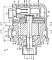
도 1은, 실시 형태에 있어서의 베인형 압축기(10)를 나타내는 단면도이다.
도 2는, 도 1 중의 Ⅱ-Ⅱ선을 따른 화살표 단면도이다.
도 3은, 도 1 중의 Ⅲ-Ⅲ선을 따른 화살표 단면도이다.
도 4는, 실시 형태에 있어서의 베인형 압축기(10)에 구비되는 흡입 포트(11a), 흡입실(12r), 제1 연통 통로(24), 제2 연통 통로(25), 제1 축 구멍(12h)을 개략적으로 나타내는 사시도이다.
도 5는, 실시 형태에 있어서의 베인형 압축기(10)에 있어서, 냉매가 흐르는 모양을 나타내는 사시도이다.
도 6은, 제1 연통 통로(24) 및 제2 연통 통로(25)의 다른 구성을 나타내는 사시도이다.1 is a cross-sectional view showing a
Fig. 2 is a cross-sectional view taken along the line II-II in Fig. 1; Fig.
3 is a cross-sectional view taken along the line III-III in Fig.
4 is a sectional view showing the
Fig. 5 is a perspective view showing a state in which the refrigerant flows in the
6 is a perspective view showing another configuration of the
(발명을 실시하기 위한 형태)(Mode for carrying out the invention)
실시 형태에 대해서, 이하, 도면을 참조하면서 설명한다. 동일한 부품 및 상당 부품에는 동일한 참조 번호를 붙이고, 중복하는 설명은 반복하지 않는 경우가 있다.Hereinafter, an embodiment will be described with reference to the drawings. The same reference numerals are given to the same parts and equivalent parts, and redundant descriptions may not be repeated.
(베인형 압축기(10))(Vane type compressor 10)
도 1은, 실시 형태에 있어서의 베인형 압축기(10)를 나타내는 단면도이다. 도 2는, 도 1 중의 Ⅱ-Ⅱ선을 따른 화살표 단면도이다. 도 3은, 도 1 중의 Ⅲ-Ⅲ선을 따른 화살표 단면도이다.1 is a cross-sectional view showing a
도 1을 주로 참조하여, 베인형 압축기(10)는, 하우징(11), 샤프트(15), 축봉 장치(17), 로우터(18), 복수의 베인(19)을 구비한다. 하우징(11)은, 흡입 포트(11a) 및 토출 포트(11e)를 갖고, 실린더실(11b)을 내측에 형성한다. 본 실시 형태의 하우징(11)은, 그 구성 요소로서, 프런트 하우징(12), 리어 하우징(13), 사이드 플레이트(14)를 포함하고 있다.1, the
(프런트 하우징(12))(Front housing 12)
프런트 하우징(12)은, 실린더실 형성부(12a) 및 구획벽(12b)(제1 벽부)을 갖는다. 실린더실 형성부(12a)는, 통상의 형상을 갖고, 내측에 실린더실(11b)을 형성한다. 실린더실 형성부(12a) 내의 실린더실(11b)은, 후방에서 전방을 향하여 오목하게 형성된다. 샤프트(15)의 회전 축심(16)에 대하여 직교하는 방향에 있어서, 실린더실(11b)은, 타원형의 단면 형상을 갖는다(도 2, 도 3).The
실린더실 형성부(12a)의 외주면에는, 오목부(12f)(도 1)가 형성된다. 오목부(12f)는, 실린더실 형성부(12a)의 둘레 방향의 전체 둘레에 걸쳐 환상으로 연재(延在)한다. 오목부(12f) 및 리어 하우징(13)의 내주면에 의해, 흡입실(12r)이 구획된다. 실린더실 형성부(12a)의 외측에 형성된 흡입실(12r)은, 흡입 포트(11a)에 연통한다. 본 실시 형태의 흡입실(12r)은, 실린더실 형성부(12a)의 주위를 둘러싸는 환상의 형상을 갖고 있다(도 2).A
도 2에 나타내는 바와 같이, 실린더실 형성부(12a)에는, 제1 흡입구(22), 제2 흡입구(23)가 형성된다. 제1 흡입구(22), 제2 흡입구(23)는, 둘레 방향에 있어서 서로 떨어진 위치에 형성되고, 흡입실(12r)과 실린더실(11b)을 연통시킨다. 제1 흡입구(22), 제2 흡입구(23)는, 예를 들면, 흡입 포트(11a)로부터 흡입실(12r)을 통하여 제1 흡입구(22), 제2 흡입구(23)에 이르는 냉매 가스의 경로의 길이가 각각 동일한 길이가 되는 위치에 배치된다. 흡입실(12r), 제1 흡입구(22), 제2 흡입구(23)가, 흡입 포트(11a)와 후술하는 압축실을 연통하는 흡입 통로이다.As shown in Fig. 2, a
프런트 하우징(12)의 구획벽(12b)은, 실린더실 형성부(12a)의 전측(前側)에 위치하고, 실린더실 형성부(12a)와 일체로 형성된다. 구획벽(12b)은, 실린더실(11b)의 축 방향에 있어서의 한쪽측의 내면(11c)을 형성한다. 구획벽(12b)에는, 샤프트(15)가 삽입되는 제1 축 구멍(12h)이 형성된다. 상세는 후술하지만, 구획벽(12b)에는, 제1 연통 통로(24) 및 제2 연통 통로(25)도 형성된다.The
(리어 하우징(13), 사이드 플레이트(14))(
리어 하우징(13)은, 프런트 하우징(12)의 실린더실 형성부(12a)와 사이드 플레이트(14)를 수용한다. 리어 하우징(13)과 사이드 플레이트(14)의 사이에는, 토출 영역(35)이 형성된다. 사이드 플레이트(14)는, 실린더실(11b)과 토출 영역(35)을 구획하고 있다.The
리어 하우징(13)에는, 흡입 포트(11a), 토출 포트(11e)가 형성된다. 흡입 포트(11a)는, 흡입실(12r)을 외부에 연통시키고, 토출 포트(11e)는, 토출 영역(35)을 외부에 연통시킨다. 흡입실(12r), 흡입 포트(11a), 실린더실(11b)은, 지름 방향에 있어서 겹치는 위치에 배치된다. 흡입 행정 중의 실린더실(11b)(압축실(21))과 흡입실(12r)은, 각각 제1 흡입구(22), 제2 흡입구(23)(도 2)를 통하여 연통한다.In the
사이드 플레이트(14)(제2 벽부)는, 프런트 하우징(12)의 실린더실 형성부(12a)의 후단면에 접합된다. 사이드 플레이트(14)는, 실린더실(11b)의 축 방향에 있어서의 다른 한쪽측의 내면(11d)을 형성한다. 사이드 플레이트(14)에는, 샤프트(15)가 삽입되는 제2 축 구멍(14h)이 형성된다.The side plate 14 (second wall portion) is joined to the rear end surface of the cylinder
(샤프트(15), 축봉 장치(17))(The
샤프트(15)는, 하우징(11) 내에 있어서 실린더실(11b)을 관통하도록 배치되고, 회전 축심(16)의 둘레로 회전 가능하게 설치된다. 본 실시 형태에 있어서는, 프런트 하우징(12)(구획벽(12b))에 형성된 제1 축 구멍(12h)의 내주면과, 사이드 플레이트(14)에 형성된 제2 축 구멍(14h)의 내주면에 의해, 샤프트(15)가 회전 가능하게 지지된다.The
축봉 장치(17)는, 하우징(11)(구획벽(12b))에 형성된 제1 축 구멍(12h)과 샤프트(15)의 외주면의 사이에 설치된다. 축봉 장치(17)는, 샤프트(15)의 외주면을 따라 냉매 가스가 누출되는 것을 방지한다.The
전술한 대로, 프런트 하우징(12)의 구획벽(12b)에는, 제1 연통 통로(24), 제2 연통 통로(25)가 관통 형성된다. 제1 연통 통로(24), 제2 연통 통로(25)는, 흡입실(12r)과 제1 축 구멍(12h)(구체적으로는, 제1 축 구멍(12h) 중, 축봉 장치(17)보다도 후측에 위치하는 부분(12k))을 연통시킨다. 흡입 포트(11a)로부터의 냉매는, 흡입실(12r), 제1 연통 통로(24), 제2 연통 통로(25)를 통해 축봉 장치(17)로 공급된다(상세는 후술함).The
(로우터(18), 베인(19))(The
로우터(18)는, 실린더실(11b) 내에 배치된다. 로우터(18)는, 샤프트(15)에 고정 부착되어 있고, 샤프트(15)와 일체로 회전할 수 있다. 로우터(18)의 외주면에는, 복수의 홈(18a)(도 2, 도 3)이 형성된다. 베인(19)은, 복수의 홈(18a)의 각각의 내측에 설치된다. 각 홈(18a)에는, 윤활유가 공급된다.The
베인(19)의 선단은, 로우터(18)의 회전에 의해 실린더실(11b)의 내주면에 접촉한다. 실린더실(11b) 중에, 압축실(21)이 형성된다. 압축실(21)은, 로우터(18)의 외주면과, 실린더실 형성부(12a)의 내벽과, 서로 이웃하는 2개의 베인(19)과, 구획벽(12b)(내면(11c))과, 사이드 플레이트(14)(내면(11d))에 의해 구획된다.The tip of the
도 1 및 도 3에 나타내는 바와 같이, 프런트 하우징(12)의 실린더실 형성부(12a)와 리어 하우징(13)의 사이에는, 토출 공간(30)이 형성된다. 토출 공간(30)은, 흡입실(12r)보다도 사이드 플레이트(14)에 가까운 측에 위치한다(도 1). 흡입실(12r) 및 토출 공간(30)은, 지름 방향에 있어서의 실린더실 형성부(12a)와 리어 하우징(13)의 사이에 위치하고, 축 방향으로 나란히 배치된다.1 and 3, a
실린더실 형성부(12a)에는, 토출 밸브(32)(도 3)에 의해 개폐되는 토출구(31)가 형성된다. 토출 행정에 있는 압축실(21)과 토출 공간(30)은, 토출구(31)를 통해 연통한다. 압축실(21)에서 압축된 냉매 가스는, 토출 밸브(32)를 밀어 젖혀 토출구(31)를 통해 토출 공간(30)으로 토출된다.The cylinder
리어 하우징(13)(도 1)의 후측에는, 사이드 플레이트(14)에 의해 토출 영역(35)이 구획 형성된다. 토출 영역(35) 내에는, 오일 분리기(36)가 설치된다. 오일 분리기(36)는, 케이스(36a), 오일 분리통(36b), 오일 통로(36c)를 갖는다. 사이드 플레이트(14) 및 케이스(36a)에는, 토출 공간(30)과 케이스(36a) 내를 연통하는 연통로(37)(도 1, 도 3)가 형성된다. 사이드 플레이트(14)에는, 토출 영역(35)에 저류된 윤활유를 홈(18a)으로 유도하기 위한 오일 공급 통로(14d)가 형성된다.On the rear side of the rear housing 13 (Fig. 1), the
(제1 연통 통로(24), 제2 연통 통로(25))(The
도 4는, 흡입 포트(11a), 흡입실(12r), 제1 연통 통로(24), 제2 연통 통로(25), 제1 축 구멍(12h)을 개략적으로 나타내는 사시도이다. 도 5는, 냉매가 흐르는 모양을 나타내는 사시도이다.4 is a perspective view schematically showing the
도 1, 도 2, 도 4를 참조하여, 전술한 대로, 프런트 하우징(12)의 실린더실 형성부(12a)에는, 제1 흡입구(22), 제2 흡입구(23)가 형성된다. 제1 흡입구(22), 제2 흡입구(23)는, 둘레 방향에 있어서 서로 떨어진 위치에 설치되고(도 2, 도 4), 흡입실(12r)과 실린더실(11b)을 연통시키고 있다. 샤프트(15)가 구동되면, 로우터(18)가 샤프트(15)와 일체로 회전하고, 로우터(18) 및 베인(19)의 동작에 의해, 압축실(21)의 용적이 변화한다. 냉매는, 흡입 포트(11a)로부터 흡입실(12r)로 흡입되고, 실린더실 형성부(12a)의 외주면을 따라 2 방향으로 분기하여, 제1 흡입구(22), 제2 흡입구(23)를 거쳐 압축실(21)로 흡입된다. 제1 흡입구(22)는, 흡입 통로(흡입실(12r))의 도중에서 개구하고, 제2 흡입구(23)도, 흡입 통로(흡입실(12r))의 도중에서 개구하고 있다(도 5 중의 화살표 DR, DR1, DR2 참조).Referring to Figs. 1, 2 and 4, a
한편, 프런트 하우징(12)의 구획벽(12b)에 형성된 제1 연통 통로(24), 제2 연통 통로(25)는, 흡입실(12r)과 제1 축 구멍(12h)(구체적으로는, 제1 축 구멍(12h) 중, 축봉 장치(17)보다도 후측에 위치하는 부분(12k))을 연통시킨다. 흡입 포트(11a)로부터의 냉매의 일부는, 흡입실(12r), 제1 연통 통로(24), 제2 연통 통로(25), 제1 축 구멍(12h)(부분(12k))을 통해 축봉 장치(17)로 공급된다(도 5 중의 화살표 AR1, AR2 참조). 제1 연통 통로(24)는, 제1 흡입구(22)보다도 흡입 포트(11a)에 가까운 측에서 개구하고 있고, 제2 연통 통로(25)는, 제2 흡입구(23)보다도 흡입 포트(11a)로부터 먼 측에서 개구하고 있다. 이하, 이들의 위치 관계에 대해서 상술한다.On the other hand, the
(제1 평면(22s), 제2 평면(23s))(The
도 2를 참조하여, 여기에서, 제1 평면(22s) 및 제2 평면(23s)을 그린다고 한다. 제1 평면(22s)은, 샤프트(15)의 회전 축심(16)의 위치를 기점으로서, 회전 축심(16)의 위치로부터 제1 흡입구(22)의 둘레 방향에 있어서의 중심 위치(22p)를 포함하도록 연재하는 2차원 평면의 형상을 갖는다(도 2 중에서는, 제1 평면(22s)이 일점쇄선을 이용하여 그려져 있음). 제1 흡입구(22)의 둘레 방향에 있어서의 중심 위치(22p)란, 회전 축심(16)에 대하여 직교하는 방향의 단면에서 제1 흡입구(22)를 본 경우에, 제1 흡입구(22)의 지름 방향의 외측에 위치하는 개구 부분의, 둘레 방향에 있어서 중심에 위치하는 부분이다.Referring to Fig. 2, it is assumed here that the
한편, 제2 평면(23s)은, 샤프트(15)의 회전 축심(16)의 위치를 기점으로서, 회전 축심(16)의 위치로부터 제2 흡입구(23)의 둘레 방향에 있어서의 중심 위치(23p)를 포함하도록 연재하는 2차원 평면의 형상을 갖는다(도 2 중에서는, 제2 평면(23s)이 이점쇄선을 이용하여 그려져 있음). 제2 흡입구(23)의 둘레 방향에 있어서의 중심 위치(23p)란, 회전 축심(16)에 대하여 직교하는 방향의 단면에서 제2 흡입구(23)를 본 경우에, 제2 흡입구(23)의 지름 방향의 외측에 위치하는 개구 부분의, 둘레 방향에 있어서 중심에 위치하는 부분이다.On the other hand, the
흡입실(12r) 내의 공간을, 공간(12r1)과 공간(12r2)의 2개로 나누었다고 한다. 공간(12r1)이란, 흡입실(12r) 중, 제1 평면(22s) 및 제2 평면(23s)에서 보아 흡입 포트(11a)에 가까운 측에 위치하는 공간이다. 공간(12r2)이란, 흡입실(12r) 중, 제1 평면(22s) 및 제2 평면(23s)에서 보아 흡입 포트(11a)로부터 먼 측에 위치하는 공간이다.It is assumed that the space in the
도 2 및 도 4를 참조하여, 본 실시 형태에 있어서는, 제1 연통 통로(24)의 제1 축 구멍(12h)과는 반대측의 단부(24a)는, 공간(12r1)에 개구하도록 위치하고 있고, 제2 연통 통로(25)의 제1 축 구멍(12h)과는 반대측의 단부(25a)는, 공간(12r2)에 개구하도록 위치하고 있다.2 and 4, in this embodiment, the
제1 연통 통로(24)의 단부(24a)가 공간(12r1)에 개구하고 있다는 것은, 회전 축심(16)에 대하여 직교하는 방향의 단면에서 제1 연통 통로(24)의 단부(24a)를 본 경우에, 단부(24a)의 통로(개구 면적) 중 절반보다도 많은 부분이, 공간(12r1) 내에 위치하고 있는 것을 의미한다. 환언하면, 회전 축심(16)에 대하여 직교하는 방향의 단면에서 제1 연통 통로(24)의 단부(24a)를 본 경우에, 단부(24a)의 개구(개구 면적) 중 절반보다도 많은 부분이, 제1 평면(22s), 제2 평면(23s)보다도 흡입 포트(11a)에 가까운 측에 위치하고 있는 것을 의미한다.The fact that the
제2 연통 통로(25)의 단부(25a)가 공간(12r2)에 개구하고 있다는 것은, 회전 축심(16)에 대하여 직교하는 방향의 단면에서 제2 연통 통로(25)의 단부(25a)를 본 경우에, 단부(25a)의 통로(개구 면적) 중 절반보다도 많은 부분이, 공간(12r2) 내에 위치하고 있는 것을 의미한다. 환언하면, 회전 축심(16)에 대하여 직교하는 방향의 단면에서 제2 연통 통로(25)의 단부(25a)를 본 경우에, 단부(25a)의 개구(개구 면적) 중 절반보다도 많은 부분이, 제1 평면(22s), 제2 평면(23s)보다도 흡입 포트(11a)로부터 먼 측에 위치하고 있는 것을 의미한다.The
(작용 및 효과)(Action and effect)
본 실시 형태의 베인형 압축기(10)(도 1)에 있어서는, 흡입실(12r), 흡입 포트(11a), 실린더실(11b)이, 지름 방향에 있어서 겹치는 위치에 배치되기 때문에, 베인형 압축기(10)를 샤프트(15)의 축 방향에 있어서 소형화할 수 있다.In the vane type compressor 10 (Fig. 1) of the present embodiment, since the
프런트 하우징(12)의 구획벽(12b)은, 실린더실 형성부(12a)와 일체로 형성되기 때문에, 구획벽(12b)과 실린더실 형성부(12a)를 다른 부품으로서 구성하는 경우에 비해 부품 점수를 적게 할 수 있다.The
본 실시 형태의 베인형 압축기(10)에 있어서는, 제1 연통 통로(24), 제2 연통 통로(25)에 의해, 흡입실(12r)과, 축봉 장치(17)가 설치되어 있는 장소(구체적으로는, 제1 축 구멍(12h) 중, 축봉 장치(17)보다도 후측에 위치하는 부분(12k))를 연통시키고 있다. 흡입실(12r) 내의 냉매의 일부는, 제1 연통 통로(24), 제2 연통 통로(25)를 통해 축봉 장치(17)로 공급된다. 축봉 장치(17)를 냉각할 수 있어, 샤프트(15)와 축봉 장치(17) 사이의 슬라이딩 부분의 윤활을 좋게 하는 것이 가능해진다.In the
전술한 대로, 제1 연통 통로(24)의 단부(24a)는, 공간(12r1)에 개구하도록 위치하고 있고, 제2 연통 통로(25)의 단부(25a)는, 공간(12r2)에 개구하도록 위치하고 있다. 도 5를 참조하여, 공간(12r1) 내를 흐르는 냉매의 흐름은, 공간(12r2) 내를 흐르는 냉매의 흐름보다도 빠르다. 환언하면, 흡입 포트(11a)와 제1 흡입구(22) 사이의 냉매의 흐름이나, 흡입 포트(11a)와 제2 흡입구(23) 사이의 냉매의 흐름은, 흡입 포트(11a)에 가까운 분(分)만큼, 공간(12r2) 내를 흐르는 냉매의 흐름에 비해 빠르다.The
따라서, 공간(12r1) 내의 압력은, 공간(12r2) 내의 압력에 비해 낮아진다. 제1 연통 통로(24)의 단부(24a)는, 공간(12r1)에 개구하도록 위치하고, 제2 연통 통로(25)의 단부(25a)는, 공간(12r2)에 개구하도록 위치하고 있다. 제1 연통 통로(24)의 단부(24a)와 제2 연통 통로(25)의 단부(25a)의 사이에는, 차압이 발생하기 쉬워진다.Therefore, the pressure in the space 12r1 becomes lower than the pressure in the space 12r2. The
제1 연통 통로(24)의 단부(24a)는 압력이 상대적으로 낮고, 제2 연통 통로(25)의 단부(25a)는 압력이 상대적으로 높아지기 쉽다. 냉매는, 제2 연통 통로(25)의 단부(25a)로부터 제1 연통 통로(24)의 단부(24a)로 흐르기 쉬워진다. 즉, 흡입실(12r) 내의 냉매를, 축봉 장치(17)를 향하여 보다 흐르기 쉽게 하는 것이 가능해진다.The pressure of the
바람직하게는, 제2 연통 통로(25)의 제1 축 구멍(12h)과는 반대측의 단부(25a)는, 중력 방향에 있어서, 제1 연통 통로(24)의 제1 축 구멍(12h)과는 반대측의 단부(24a)보다도 높은 위치에 형성되어 있으면 좋다. 흡입실(12r) 내의 냉매를, 축봉 장치(17)를 향하여 보다 흐르기 쉽게 하는 것이 가능해진다. 혹은, 동일한 효과를 얻기 위해, 제1 연통 통로(24)의 평균 유로 단면적과 제2 연통 통로(25)의 평균 유로 단면적은 동일한 것이 바람직하고, 제1 연통 통로(24)의 평균 유로 단면적이, 제2 연통 통로(25)의 평균 유로 단면적에 대하여, 0.9배 이상 1.1배 이하로 해도 좋다. 제1 연통 통로(24), 제2 연통 통로(25)의 지름에 차가 있으면, 소경의 측이 조여져 압력 손실이 발생하기 쉬워지지만, 제1 연통 통로(24), 제2 연통 통로(25)의 지름(평균 유로 단면적)을 거의 동일하게 하면, 압력 손실의 발생을 억제할 수 있다.The
본 실시 형태의 흡입실(12r)(도 2)은, 실린더실 형성부(12a)의 주위를 둘러싸는 환상의 형상을 갖고 있다. 흡입실(12r)이 실린더실 형성부(12a)의 주위를 둘러싸는 환상의 형상을 갖고 있지 않은 경우에 비하면, 베인형 압축기(10)는, 흡입실(12r)의 용적을 가능한 한 확보할 수 있다. 또한, 제1 흡입구(22)(도 2) 및 제2 흡입구(23)(도 2)에 의해 흡입실(12r)과 실린더실(11b)을 연통시키는 것이 가능하면, 흡입실(12r)은, 반드시, 실린더실 형성부(12a)의 주위를 둘러싸는 환상의 형상을 갖고 있지 않아도 좋다. 도 5를 참조하여, 예를 들면, 공간(12r2)은, 영역(12r3)에 있어서 둘레 방향으로 분단되어 있어도 좋다.The
도 6은, 제1 연통 통로(24) 및 제2 연통 통로(25)의 다른 구성을 나타내는 사시도이다. 제1 연통 통로(24)는, 복수의 관통 구멍(241, 242)으로 구성되어 있다. 제2 연통 통로(25)도, 복수의 관통 구멍(251, 252)으로 구성되어 있다. 즉, 제1 연통 통로(24) 및 제2 연통 통로(25) 중 적어도 한쪽은, 복수의 관통 구멍으로 구성되어 있어도 상관없다. 당해 구성에 의해서도, 상기와 동일한 작용 및 효과를 얻을 수 있다.6 is a perspective view showing another configuration of the
도 6에 나타내는 바와 같이, 제1 연통 통로(24)가, 관통 구멍(241)(제1 관통 구멍)과, 관통 구멍(241)보다도 작은 평균 유로 단면적을 갖는 관통 구멍(242)(제2 관통 구멍)으로 구성되는 경우에는, 관통 구멍(241)은, 관통 구멍(242)보다도 제2 흡입구(23)에 가까운 측에서 개구하고 있는 것이 바람직하다. 도 6 중의 화살표는, 냉매가 흐르는 방향을 나타내고 있다. 당해 구성에 의하면, 축봉 장치(17)를 통과함으로써 가열된 냉매 가스는, 대경의 관통 구멍(241)을 통과한 후, 흡입실(12r) 내를 재순환하지 않고, 제2 흡입구(23)로부터 압축실 내로 흡입되기 쉬워진다. 즉, 도 6 중의 화살표 AR3에 나타내는 바와 같이, 대경의 관통 구멍(241)이 제2 흡입구(23)의 가까이에 있음으로써, 관통 구멍(241)으로부터의 흐름이 강하고, 냉매 가스는 제2 흡입구(23)에 들어가기 쉬워져, 가열된 냉매 가스가 재차 축봉 장치(17)의 냉각에 이용되는 것을 억제 가능해진다.6, the
이상, 실시 형태에 대해서 설명했지만, 상기의 개시 내용은 모든 점에서 예시로서 제한적인 것은 아니다. 본 발명의 기술적 범위는 특허청구의 범위에 의해 나타나고, 특허청구의 범위와 균등의 의미 및 범위 내에서의 모든 변경이 포함되는 것이 의도된다.Although the embodiments have been described above, the above disclosure is not limited by the examples in all respects. It is intended that the technical scope of the present invention be indicated by the appended claims and that all changes within the meaning and range of equivalency of the claims are intended to be included.
10 : 베인형 압축기
11 : 하우징
11a : 흡입 포트
11b : 실린더실
11c, 11d : 내면
11e : 토출 포트
12 : 프런트 하우징
12a : 실린더실 형성부
12b : 구획벽
12f : 오목부
12h : 제1 축 구멍
12k : 부분
12r1, 12r2 : 공간
12r : 흡입실
12r3 : 영역
13 : 리어 하우징
14 : 사이드 플레이트
14h : 제2 축 구멍
15 : 샤프트
15d : 오일 공급 통로
16 : 회전 축심
17 : 축봉 장치
18 : 로우터
18a : 홈
19 : 베인
21 : 압축실
22 : 제1 흡입구
22p, 23p : 중심 위치
22s : 제1 평면
23 : 제2 흡입구
23s : 제2 평면
24 : 제1 연통 통로
24a, 25a : 단부
25 : 제2 연통 통로
30 : 토출 공간
31 : 토출구
32 : 토출 밸브
35 : 토출 영역
36 : 오일 분리기
36a : 케이스
36b : 오일 분리통
36c : 오일 통로
37 : 연통로
241, 242, 251, 252 : 관통 구멍
AR1, AR2, AR3, DR, DR1, DR2 : 화살표10: Vane type compressor
11: Housing
11a: Suction port
11b: cylinder chamber
11c, 11d: inner surface
11e: Discharge port
12: Front housing
12a: cylinder chamber forming portion
12b:
12f:
12h: first shaft hole
12k: part
12r1, 12r2: Space
12r: suction chamber
12r3: area
13: Rear housing
14: Side plate
14h: Second shaft hole
15: Shaft
15d: oil supply passage
16:
17:
18: rotor
18a: Home
19: Vane
21: compression chamber
22: first inlet
22p, 23p: center position
22s: 1st plane
23: Second intake port
23s: second plane
24: first communication passage
24a, 25a: end
25: second communication passage
30: Discharge space
31:
32: Discharge valve
35: Discharge area
36: Oil separator
36a: Case
36b: Oil separator
36c: Oil passage
37: communicating path
241, 242, 251, 252: through holes
AR1, AR2, AR3, DR, DR1, DR2: Arrow
Claims (5)
상기 하우징 내에 배치되어, 회전 축심의 둘레로 회전 가능하게 설치된 샤프트와,
상기 하우징과 상기 샤프트의 사이에 설치된 축봉 장치와,
복수의 홈을 갖고, 상기 실린더실 내에서 상기 샤프트와 일체 회전하는 로우터와,
복수의 상기 홈의 각각의 내측에 설치된 베인을 구비하고,
상기 하우징은,
통상(筒狀)의 형상을 갖고, 내측에 상기 실린더실을 형성하는 실린더실 형성부와,
상기 샤프트가 삽입되는 제1 축 구멍을 갖고, 상기 실린더실의 축 방향에 있어서의 한쪽측의 내면을 형성하는 제1 벽부와,
상기 샤프트가 삽입되는 제2 축 구멍을 갖고, 상기 실린더실의 축 방향에 있어서의 다른 한쪽측의 내면을 형성하는 제2 벽부를 포함하고,
상기 실린더실 내에, 상기 로우터의 외주면, 상기 베인, 상기 제1 벽부 및 상기 제2 벽부에 의해 압축실이 구획되고,
상기 흡입 포트와 상기 압축실을 연통하는 흡입 통로가 형성되고,
상기 실린더실 형성부에는, 상기 흡입 통로와 상기 실린더실을 연통시키는 제1 흡입구 및 제2 흡입구가 둘레 방향에 있어서 서로 떨어진 위치에 형성되고,
상기 축봉 장치는, 상기 제1 축 구멍과 상기 샤프트의 사이에 설치되고,
상기 제1 벽부에는, 상기 흡입 통로와 상기 제1 축 구멍을 연통시켜, 상기 흡입 포트로부터의 냉매를 상기 축봉 장치로 공급하기 위한 제1 연통 통로 및 제2 연통 통로가 관통 형성되고,
상기 제1 흡입구와 상기 제2 흡입구 중 적어도 한쪽은, 상기 흡입 통로의 도중에 개구하고,
상기 제1 연통 통로는, 상기 제2 흡입구보다도 상기 흡입 포트에 가까운 측에서 개구하도록 위치하고,
상기 제2 연통 통로는, 상기 제1 흡입구보다도 상기 흡입 포트로부터 먼 측에서 개구하도록 위치하고 있는,
베인형 압축기.A housing having a suction port and having a cylinder chamber formed inside,
A shaft disposed in the housing and rotatably provided around the rotation axis;
A shaft end device provided between the housing and the shaft,
A rotor having a plurality of grooves and rotating integrally with the shaft in the cylinder chamber;
And a vane provided inside each of the plurality of grooves,
The housing includes:
A cylinder chamber forming portion having a cylindrical shape and forming the cylinder chamber on the inner side;
A first wall portion having a first shaft hole into which the shaft is inserted and forming an inner surface on one side in the axial direction of the cylinder chamber,
And a second wall portion having a second shaft hole into which the shaft is inserted and forming an inner surface on the other side in the axial direction of the cylinder chamber,
The compression chamber is partitioned by the outer peripheral surface of the rotor, the vane, the first wall portion, and the second wall portion in the cylinder chamber,
A suction passage communicating the suction port and the compression chamber is formed,
Wherein the cylinder chamber forming portion is formed with a first intake port and a second intake port communicating the intake passage and the cylinder chamber at positions away from each other in the circumferential direction,
Wherein the shaft device is provided between the first shaft hole and the shaft,
Wherein the first wall portion is formed with a first communication passage and a second communication passage for communicating the suction passage and the first shaft hole and for supplying the refrigerant from the suction port to the shaft sealing device,
At least one of the first suction port and the second suction port opens in the middle of the suction passage,
The first communication passage is positioned to open at a side closer to the suction port than the second suction port,
Wherein the second communication passage is located so as to open at a side farther from the suction port than the first suction port,
Bevine type compressor.
상기 흡입 통로는, 상기 실린더실 형성부의 주위를 둘러싸는 환상의 형상을 갖는 흡입실을 포함하는,
베인형 압축기.The method according to claim 1,
Wherein the suction passage includes a suction chamber having an annular shape surrounding the periphery of the cylinder chamber forming portion,
Bevine type compressor.
상기 제2 연통 통로의 상기 제1 축 구멍과는 반대측의 단부는, 중력 방향에 있어서, 상기 제1 연통 통로의 상기 제1 축 구멍과는 반대측의 단부보다도 높은 위치에 형성되어 있는,
베인형 압축기.The method according to claim 1,
The end of the second communication passage on the opposite side of the first shaft hole is formed at a position higher than the end of the first communication passage on the opposite side of the first shaft hole in the gravity direction,
Bevine type compressor.
상기 제1 연통 통로 및 상기 제2 연통 통로 중 적어도 한쪽은, 복수의 관통 구멍으로 구성되어 있는,
베인형 압축기.4. The method according to any one of claims 1 to 3,
Wherein at least one of the first communication passage and the second communication passage includes a plurality of through holes,
Bevine type compressor.
상기 제1 연통 통로는, 제1 관통 구멍과, 상기 제1 관통 구멍보다도 작은 평균 유로 단면적을 갖는 제2 관통 구멍으로 구성되고,
상기 제1 관통 구멍은, 상기 제2 관통 구멍보다도 상기 제2 흡입구에 가까운 측에서 개구하고 있는,
베인형 압축기.4. The method according to any one of claims 1 to 3,
Wherein the first communication passage includes a first through hole and a second through hole having an average flow path cross sectional area smaller than that of the first through hole,
Wherein the first through hole is opened at a side closer to the second suction port than the second through hole,
Bevine type compressor.
Applications Claiming Priority (2)
| Application Number | Priority Date | Filing Date | Title |
|---|---|---|---|
| JPJP-P-2016-070373 | 2016-03-31 | ||
| JP2016070373A JP6350576B2 (en) | 2016-03-31 | 2016-03-31 | Vane type compressor |
Publications (2)
| Publication Number | Publication Date |
|---|---|
| KR20170113402A true KR20170113402A (en) | 2017-10-12 |
| KR101860400B1 KR101860400B1 (en) | 2018-05-23 |
Family
ID=60005745
Family Applications (1)
| Application Number | Title | Priority Date | Filing Date |
|---|---|---|---|
| KR1020170040732A Expired - Fee Related KR101860400B1 (en) | 2016-03-31 | 2017-03-30 | Vane compressor |
Country Status (3)
| Country | Link |
|---|---|
| JP (1) | JP6350576B2 (en) |
| KR (1) | KR101860400B1 (en) |
| CN (1) | CN107269527B (en) |
Families Citing this family (2)
| Publication number | Priority date | Publication date | Assignee | Title |
|---|---|---|---|---|
| JP2019100234A (en) * | 2017-11-30 | 2019-06-24 | 株式会社豊田自動織機 | Vane-type compressor |
| CN110374873A (en) * | 2019-08-20 | 2019-10-25 | 泓道(上海)科技有限公司 | Sliding-vane air compressor |
Family Cites Families (8)
| Publication number | Priority date | Publication date | Assignee | Title |
|---|---|---|---|---|
| JPS59181292U (en) * | 1983-04-25 | 1984-12-03 | 株式会社ボッシュオートモーティブ システム | vane compressor |
| JPH10252675A (en) * | 1997-03-13 | 1998-09-22 | Matsushita Electric Ind Co Ltd | Vane rotary compressor |
| JP2002250290A (en) * | 2001-02-23 | 2002-09-06 | Zexel Valeo Climate Control Corp | Vane type compressor |
| JP5527349B2 (en) * | 2012-04-09 | 2014-06-18 | 株式会社豊田自動織機 | Vane type compressor |
| JP5708571B2 (en) * | 2012-06-20 | 2015-04-30 | 株式会社豊田自動織機 | Tandem vane compressor |
| JP5825367B2 (en) * | 2013-01-31 | 2015-12-02 | 株式会社豊田自動織機 | Vane type compressor |
| JP6042260B2 (en) * | 2013-04-26 | 2016-12-14 | カルソニックカンセイ株式会社 | Gas compressor |
| JP6083408B2 (en) * | 2014-03-25 | 2017-02-22 | 株式会社豊田自動織機 | Vane type compressor |
-
2016
- 2016-03-31 JP JP2016070373A patent/JP6350576B2/en not_active Expired - Fee Related
-
2017
- 2017-03-30 CN CN201710202053.5A patent/CN107269527B/en not_active Expired - Fee Related
- 2017-03-30 KR KR1020170040732A patent/KR101860400B1/en not_active Expired - Fee Related
Also Published As
| Publication number | Publication date |
|---|---|
| KR101860400B1 (en) | 2018-05-23 |
| CN107269527B (en) | 2019-04-02 |
| JP6350576B2 (en) | 2018-07-04 |
| JP2017180347A (en) | 2017-10-05 |
| CN107269527A (en) | 2017-10-20 |
Similar Documents
| Publication | Publication Date | Title |
|---|---|---|
| JP5774134B2 (en) | Vane type compressor | |
| US20120148434A1 (en) | Scroll Fluid Machine | |
| RU2480627C1 (en) | Impeller pump | |
| CN105909522B (en) | Vane compressor | |
| JP6083408B2 (en) | Vane type compressor | |
| KR101860400B1 (en) | Vane compressor | |
| JP6428200B2 (en) | Electric compressor | |
| JP6115228B2 (en) | Vane type compressor | |
| JP5825367B2 (en) | Vane type compressor | |
| JP2019065745A (en) | Vane type compressor | |
| KR102004353B1 (en) | Scroll compressor with a back pressure chamber | |
| JP5626260B2 (en) | Vane type compressor | |
| WO2017002536A1 (en) | Scroll compressor | |
| JP6156158B2 (en) | Vane type compressor | |
| JP2017141802A (en) | Rotary compressor and refrigeration cycle equipment | |
| KR101964588B1 (en) | Vane rotary compressor | |
| JP6717232B2 (en) | Vane compressor | |
| JPWO2018142466A1 (en) | Compressor | |
| JP2019027372A (en) | Compressor | |
| JP6388000B2 (en) | Compressor | |
| KR20160005499A (en) | Scroll compressor with a seal for a back pressure chamber | |
| JP2018168780A (en) | Vane type compressor | |
| JP2023119329A (en) | Vane-type compressor | |
| KR20210146131A (en) | Rotary Compressor | |
| JP2020148159A (en) | Compressor |
Legal Events
| Date | Code | Title | Description |
|---|---|---|---|
| A201 | Request for examination | ||
| PA0109 | Patent application |
St.27 status event code: A-0-1-A10-A12-nap-PA0109 |
|
| PA0201 | Request for examination |
St.27 status event code: A-1-2-D10-D11-exm-PA0201 |
|
| PG1501 | Laying open of application |
St.27 status event code: A-1-1-Q10-Q12-nap-PG1501 |
|
| E701 | Decision to grant or registration of patent right | ||
| PE0701 | Decision of registration |
St.27 status event code: A-1-2-D10-D22-exm-PE0701 |
|
| GRNT | Written decision to grant | ||
| PR0701 | Registration of establishment |
St.27 status event code: A-2-4-F10-F11-exm-PR0701 |
|
| PR1002 | Payment of registration fee |
St.27 status event code: A-2-2-U10-U11-oth-PR1002 Fee payment year number: 1 |
|
| PG1601 | Publication of registration |
St.27 status event code: A-4-4-Q10-Q13-nap-PG1601 |
|
| PC1903 | Unpaid annual fee |
St.27 status event code: A-4-4-U10-U13-oth-PC1903 Not in force date: 20210517 Payment event data comment text: Termination Category : DEFAULT_OF_REGISTRATION_FEE |
|
| PC1903 | Unpaid annual fee |
St.27 status event code: N-4-6-H10-H13-oth-PC1903 Ip right cessation event data comment text: Termination Category : DEFAULT_OF_REGISTRATION_FEE Not in force date: 20210517 |