KR20180000741A - 오염방지 장치 하우징을 포밍하는 장치 및 방법 - Google Patents
오염방지 장치 하우징을 포밍하는 장치 및 방법 Download PDFInfo
- Publication number
- KR20180000741A KR20180000741A KR1020177036764A KR20177036764A KR20180000741A KR 20180000741 A KR20180000741 A KR 20180000741A KR 1020177036764 A KR1020177036764 A KR 1020177036764A KR 20177036764 A KR20177036764 A KR 20177036764A KR 20180000741 A KR20180000741 A KR 20180000741A
- Authority
- KR
- South Korea
- Prior art keywords
- coarse
- state
- segments
- housing
- design
- Prior art date
- Legal status (The legal status is an assumption and is not a legal conclusion. Google has not performed a legal analysis and makes no representation as to the accuracy of the status listed.)
- Granted
Links
Images











Classifications
-
- B—PERFORMING OPERATIONS; TRANSPORTING
- B21—MECHANICAL METAL-WORKING WITHOUT ESSENTIALLY REMOVING MATERIAL; PUNCHING METAL
- B21K—MAKING FORGED OR PRESSED METAL PRODUCTS, e.g. HORSE-SHOES, RIVETS, BOLTS OR WHEELS
- B21K21/00—Making hollow articles not covered by a single preceding sub-group
- B21K21/16—Remodelling hollow bodies with respect to the shape of the cross-section
-
- B—PERFORMING OPERATIONS; TRANSPORTING
- B21—MECHANICAL METAL-WORKING WITHOUT ESSENTIALLY REMOVING MATERIAL; PUNCHING METAL
- B21D—WORKING OR PROCESSING OF SHEET METAL OR METAL TUBES, RODS OR PROFILES WITHOUT ESSENTIALLY REMOVING MATERIAL; PUNCHING METAL
- B21D41/00—Application of procedures in order to alter the diameter of tube ends
- B21D41/04—Reducing; Closing
-
- B—PERFORMING OPERATIONS; TRANSPORTING
- B21—MECHANICAL METAL-WORKING WITHOUT ESSENTIALLY REMOVING MATERIAL; PUNCHING METAL
- B21D—WORKING OR PROCESSING OF SHEET METAL OR METAL TUBES, RODS OR PROFILES WITHOUT ESSENTIALLY REMOVING MATERIAL; PUNCHING METAL
- B21D15/00—Corrugating tubes
- B21D15/02—Corrugating tubes longitudinally
-
- B—PERFORMING OPERATIONS; TRANSPORTING
- B21—MECHANICAL METAL-WORKING WITHOUT ESSENTIALLY REMOVING MATERIAL; PUNCHING METAL
- B21D—WORKING OR PROCESSING OF SHEET METAL OR METAL TUBES, RODS OR PROFILES WITHOUT ESSENTIALLY REMOVING MATERIAL; PUNCHING METAL
- B21D22/00—Shaping without cutting, by stamping, spinning, or deep-drawing
- B21D22/02—Stamping using rigid devices or tools
-
- B—PERFORMING OPERATIONS; TRANSPORTING
- B21—MECHANICAL METAL-WORKING WITHOUT ESSENTIALLY REMOVING MATERIAL; PUNCHING METAL
- B21D—WORKING OR PROCESSING OF SHEET METAL OR METAL TUBES, RODS OR PROFILES WITHOUT ESSENTIALLY REMOVING MATERIAL; PUNCHING METAL
- B21D22/00—Shaping without cutting, by stamping, spinning, or deep-drawing
- B21D22/02—Stamping using rigid devices or tools
- B21D22/025—Stamping using rigid devices or tools for tubular articles
-
- B—PERFORMING OPERATIONS; TRANSPORTING
- B21—MECHANICAL METAL-WORKING WITHOUT ESSENTIALLY REMOVING MATERIAL; PUNCHING METAL
- B21D—WORKING OR PROCESSING OF SHEET METAL OR METAL TUBES, RODS OR PROFILES WITHOUT ESSENTIALLY REMOVING MATERIAL; PUNCHING METAL
- B21D41/00—Application of procedures in order to alter the diameter of tube ends
-
- B—PERFORMING OPERATIONS; TRANSPORTING
- B21—MECHANICAL METAL-WORKING WITHOUT ESSENTIALLY REMOVING MATERIAL; PUNCHING METAL
- B21D—WORKING OR PROCESSING OF SHEET METAL OR METAL TUBES, RODS OR PROFILES WITHOUT ESSENTIALLY REMOVING MATERIAL; PUNCHING METAL
- B21D51/00—Making hollow objects
- B21D51/02—Making hollow objects characterised by the structure of the objects
- B21D51/10—Making hollow objects characterised by the structure of the objects conically or cylindrically shaped objects
-
- B—PERFORMING OPERATIONS; TRANSPORTING
- B21—MECHANICAL METAL-WORKING WITHOUT ESSENTIALLY REMOVING MATERIAL; PUNCHING METAL
- B21J—FORGING; HAMMERING; PRESSING METAL; RIVETING; FORGE FURNACES
- B21J9/00—Forging presses
- B21J9/02—Special design or construction
- B21J9/06—Swaging presses; Upsetting presses
-
- B—PERFORMING OPERATIONS; TRANSPORTING
- B23—MACHINE TOOLS; METAL-WORKING NOT OTHERWISE PROVIDED FOR
- B23P—METAL-WORKING NOT OTHERWISE PROVIDED FOR; COMBINED OPERATIONS; UNIVERSAL MACHINE TOOLS
- B23P15/00—Making specific metal objects by operations not covered by a single other subclass or a group in this subclass
-
- F—MECHANICAL ENGINEERING; LIGHTING; HEATING; WEAPONS; BLASTING
- F01—MACHINES OR ENGINES IN GENERAL; ENGINE PLANTS IN GENERAL; STEAM ENGINES
- F01N—GAS-FLOW SILENCERS OR EXHAUST APPARATUS FOR MACHINES OR ENGINES IN GENERAL; GAS-FLOW SILENCERS OR EXHAUST APPARATUS FOR INTERNAL-COMBUSTION ENGINES
- F01N3/00—Exhaust or silencing apparatus having means for purifying, rendering innocuous, or otherwise treating exhaust
- F01N3/08—Exhaust or silencing apparatus having means for purifying, rendering innocuous, or otherwise treating exhaust for rendering innocuous
- F01N3/10—Exhaust or silencing apparatus having means for purifying, rendering innocuous, or otherwise treating exhaust for rendering innocuous by thermal or catalytic conversion of noxious components of exhaust
- F01N3/24—Exhaust or silencing apparatus having means for purifying, rendering innocuous, or otherwise treating exhaust for rendering innocuous by thermal or catalytic conversion of noxious components of exhaust characterised by constructional aspects of converting apparatus
- F01N3/28—Construction of catalytic reactors
-
- F—MECHANICAL ENGINEERING; LIGHTING; HEATING; WEAPONS; BLASTING
- F01—MACHINES OR ENGINES IN GENERAL; ENGINE PLANTS IN GENERAL; STEAM ENGINES
- F01N—GAS-FLOW SILENCERS OR EXHAUST APPARATUS FOR MACHINES OR ENGINES IN GENERAL; GAS-FLOW SILENCERS OR EXHAUST APPARATUS FOR INTERNAL-COMBUSTION ENGINES
- F01N3/00—Exhaust or silencing apparatus having means for purifying, rendering innocuous, or otherwise treating exhaust
- F01N3/08—Exhaust or silencing apparatus having means for purifying, rendering innocuous, or otherwise treating exhaust for rendering innocuous
- F01N3/10—Exhaust or silencing apparatus having means for purifying, rendering innocuous, or otherwise treating exhaust for rendering innocuous by thermal or catalytic conversion of noxious components of exhaust
- F01N3/24—Exhaust or silencing apparatus having means for purifying, rendering innocuous, or otherwise treating exhaust for rendering innocuous by thermal or catalytic conversion of noxious components of exhaust characterised by constructional aspects of converting apparatus
- F01N3/28—Construction of catalytic reactors
- F01N3/2803—Construction of catalytic reactors characterised by structure, by material or by manufacturing of catalyst support
- F01N3/2807—Metal other than sintered metal
-
- Y—GENERAL TAGGING OF NEW TECHNOLOGICAL DEVELOPMENTS; GENERAL TAGGING OF CROSS-SECTIONAL TECHNOLOGIES SPANNING OVER SEVERAL SECTIONS OF THE IPC; TECHNICAL SUBJECTS COVERED BY FORMER USPC CROSS-REFERENCE ART COLLECTIONS [XRACs] AND DIGESTS
- Y10—TECHNICAL SUBJECTS COVERED BY FORMER USPC
- Y10T—TECHNICAL SUBJECTS COVERED BY FORMER US CLASSIFICATION
- Y10T29/00—Metal working
- Y10T29/49—Method of mechanical manufacture
- Y10T29/49398—Muffler, manifold or exhaust pipe making
-
- Y—GENERAL TAGGING OF NEW TECHNOLOGICAL DEVELOPMENTS; GENERAL TAGGING OF CROSS-SECTIONAL TECHNOLOGIES SPANNING OVER SEVERAL SECTIONS OF THE IPC; TECHNICAL SUBJECTS COVERED BY FORMER USPC CROSS-REFERENCE ART COLLECTIONS [XRACs] AND DIGESTS
- Y10—TECHNICAL SUBJECTS COVERED BY FORMER USPC
- Y10T—TECHNICAL SUBJECTS COVERED BY FORMER US CLASSIFICATION
- Y10T29/00—Metal working
- Y10T29/53—Means to assemble or disassemble
- Y10T29/53709—Overedge assembling means
Landscapes
- Engineering & Computer Science (AREA)
- Mechanical Engineering (AREA)
- Chemical & Material Sciences (AREA)
- Chemical Kinetics & Catalysis (AREA)
- Combustion & Propulsion (AREA)
- Toxicology (AREA)
- Health & Medical Sciences (AREA)
- General Engineering & Computer Science (AREA)
- Gripping On Spindles (AREA)
- Jigs For Machine Tools (AREA)
- Shaping Metal By Deep-Drawing, Or The Like (AREA)
- Lining And Supports For Tunnels (AREA)
- Automatic Assembly (AREA)
- Forging (AREA)
Abstract
공구 조립체는 내면에 의해 적어도 부분적으로 한정되는 보어(bore)를 갖는 링 부분과, 후방 판과 다수의 가느다란 조 세그먼트들을 갖는 삽입 부분을 포함하고, 각각의 조 세그먼트는 후방 판과 결합되는 후방 끝 부분 사이에 있다. 삽입 부분이 개방 상태에서 폐쇄 상태로 이동될 때, 링 부분의 내면은 조 세그먼트들을 내면으로 이동되게 하여 조 세그먼트들이 전체 외면과 실질적으로 결합되게 하고 외면을 초기 위치로부터 디자인 위치로 이동시키며, 초기 외부 프로파일을 디자인 외부 프로파일로 감소시켜 공작물을 하우징으로 포밍한다.
Description
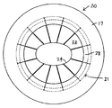
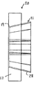
도 1b는 도 1a의 공구 조립체의 측면도.
도 1c는 도 1a의 조 세그먼트들의 확대 정면도.
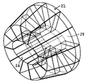
도 1d는 도 1a-1c의 조 세그먼트들의 등각투영도(isometric view).
도 2a는 본 발명의 조 세그먼트 서브조립체 실시예의 정면도.
도 2b는 도 2a의 조 세그먼트 서브조립체의 등각투영도.
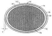
도 3은 하우징에 내에 브럭 및 매트를 갖춘 하우징의 확대 정면도.,
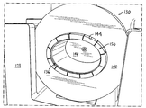
도 4는 조 세그먼트들이 외면과 결합하고 있는 결합상태를 축소 상태로 보여주는 본 발명의 공구 조립체 실시예의 등각투영도.
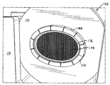
도 5는 하우징에 위치된 브럭 및 매트를 보여주는 도 4의 공구 조립체의 등각투영도.
도 6a는 제1상태에서 조 세그먼트들을 갖는 본 발명의 삽입 부분 실시예의 확대 등각투영도.
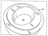
도 6b는 본 발명의 링 부분 실시예의 등각투영도.
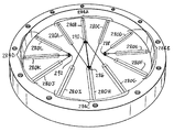
도 6c는 본 발명의 공구 조립체 실시예의 등각투영도.
도 6d는 도 6c의 공구 조립체의 다른 등각투영도.
도 6e는 조 세그먼트들이 제2상태에 있는 도 6c의 공구 조립체의 다른 등각투영도.
도 6f는 본 발명의 후방 판의 다른 실시예를 확대한 등각투영도.
도 6g는 링 부분 및/또는 삽입 부분의 이동방향이 개략적으로 표시된 도 6f의 후방 판의 등각투영도.
도 7a는 도 6a의 삽입 부분의 축소 정면도.
도 7b는 도 7a의 삽입 부분의 측면도.
도 8a는 조 세그먼트들이 제2상태에 있는 도 7a의 삽입 부분의 정면도.
도 8b는 도 8a의 삽입 부분의 측면도.
도 9a는 본 발명의 조 세그먼트 실시예의 확대 평면도.
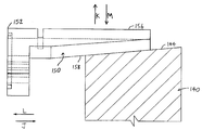
도 9b는 도 9a의 조 세그먼트의 측면도.
도 9c는 링 부분의 내면과 결합되는 도 9a의 조 세그먼트를 보여주는 확대 단면도.
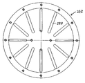
도 10a는 도 6f의 후방 판의 축소 정면도.
도 10b는 도 10a의 후방 판의 측면도.
도 11은 본 발명의 삽입 부분의 다른 실시예의 정면도.
도 12a는 조 세그먼트가 위치된 도 6f의 후방 판의 축소 정면도.
도 12b는 도 12a의 후방 판과 조 세그먼트의 측면도.
도 13a는 조 세그먼트들이 제1상태에 있는 본 발명의 공구 조립체의 다른 실시예의 정면도.
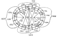
도 13b는 도 13a의 공구 조립체의 확대 정면도.
도 14는 조 세그먼트들이 제2상태에 있는 도 13a의 공구 조립체의 축소 정면도.
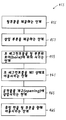
도 15a는 본 발명의 방법의 실시예의 개략 블록도.
도 15b는 본 발명의 방법의 다른 실시예의 개략 블록도.
도 15c는 본 발명의 방법의 또 다른 실시예의 개략 블록도.
132: 공작물
134: 초기 외부 프로파일
135: 외면
136: 하우징
138: 비구면 디자인 외부 프로파일
140: 링 부분
142: 보어
144: 내면
146: 삽입 부분
148: 후방 판
150: 다수의 가느다란 조 세그먼트
152: 후방 끝 부분;
152: 전방 끝 부분;
154: 내면
156: 적어도 부분적으로 테이퍼진 외면
Claims (14)
- 초기 위치로부터 감소된 설계위치에서 외부 표면에 의해 적어도 부분적으로 한정된 정의된 비 원형 디자인 외부 프로파일을 갖는 하우징 내로 초기 위치에서 외부 표면에 의해 적어도 부분적으로 한정되는 외부 프로파일을 갖는 공작물을 형성하기 위한 공구 조립체로서, 각각이 상기 외부 표면과 맞물리기 위한 내부 표면을 갖는 다수의 조 세그먼트와;
상기 조 세그먼트는 공작물을 수용할 수 있는 개구부를 한정하는 제 1 상태와 상기 조 세그먼트의 내부 표면이 하우징의 디자인 외부 프로파일을 실질적으로 한정하는 제 2 상태 사이에서 이동 가능하게 되고, 각각의 상기 내부 표면이 설계 외부 프로파일의 각 부분을 한정하게 되며;
각각의 상기 내부 표면은 상기 내부 표면에 의해 한정된 설계 외부 프로파일의 부분과 실질적으로 일치하는 설정된 종점을 중심으로 하는 반경에 의해 한정되는 설정된 종점을 가지며, 상기 내부 표면은 각각 다수의 설정된 종점과 관련되어 있고;
각각의 상기 조 세그먼트는 상기 제 1 상태로부터 제 2 상태로 설정된 종점을 향해 이동될 때 그 소정 경로를 따라 이동 가능하고, 상기 제 2 상태로부터 제 1 상태로 설정된 종점으로부터 멀어 질 때, 설정된 종점을 향해 이동가능하게 되며;
상기 조 세그먼트 중 선택된 하나를 이동시키도록 구성되어 상기 제 1 및 제 2 상태 사이에서 상기 조 세그먼트를 이동시키기 위한 다수의 유압 실린더를 포함하는 공구 조립체. - 제 1항에 있어서, 상기 유압 실린더는 상기 하우징을 형성하기 위해 상기 조 세그먼트와 상기 작업편을 실질적으로 동시에 결합시키도록 제어되는 공구 조립체.
- 제 1항에 있어서, 상기 설정된 종점들 중 제 1 종점은 상기 설정된 종점들 중 제 2 종점과 이격되어 있는 것을 특징으로 하는 공구 조립체.
- 제 3항에 있어서, 상기 설정된 종점들 중 상기 제 1 종점은 제 1 거리만큼 관련된 내부 표면으로부터 이격되고, 상기 설정된 종점들 중 상기 제 2 종점은 제 2 거리만큼 관련된 내부 표면으로부터 이격되며, 제 1 거리가 제 2 거리보다 큰 공구 조립체.
- 제 4항에 있어서, 상기 설정된 종점들 중 제 3 종점은 상기 설정된 종점들 중 제 4 종점으로부터 떨어져 있고 상기 제 1 및 제 2 설정된 종점들로부터 멀어지는 것을 특징으로 하는 공구 조립체.
- 제 5항에 있어서, 상기 비 원형 디자인은 타원형인 것을 특징으로 하는 공구 조립체.
- 제 6항에 있어서, 상기 공구 조립체는 촉매 변환기를 형성하도록 되어 있는 것을 특징으로 하는 공구 조립체.
- 초기 위치로부터 감소된 설계위치에서 외부 표면에 의해 적어도 부분적으로 한정된 정의된 비 원형 디자인 외부 프로파일을 갖는 하우징 내로 초기 위치에서 외부 표면에 의해 적어도 부분적으로 한정되는 외부 프로파일을 갖는 공작물을 형성하는 방법으로서, (a) 각각이 상기 외부 표면과 맞물리기 위한 내부 표면을 갖는 다수의 조 세그먼트를 제공하는 단계와;
상기 조 세그먼트는 공작물을 수용할 수 있는 개구부를 한정하는 제 1 상태와 상기 조 세그먼트의 내부 표면이 하우징의 디자인 외부 프로파일을 실질적으로 한정하는 제 2 상태 사이에서 이동 가능하게 되고, 각각의 상기 내부 표면이 설계 외부 프로파일의 각 부분을 한정하며;
각각의 상기 내부 표면은 상기 내부 표면에 의해 한정된 설계 외부 프로파일의 부분과 실질적으로 일치하는 설정된 종점을 중심으로 하는 반경에 의해 한정되는 설정된 종점을 가지며, 상기 내부 표면은 각각 다수의 설정된 종점과 관련되고;
각각의 상기 조 세그먼트는 상기 제 1 상태로부터 제 2 상태로 설정된 종점을 향해 이동될 때 그 소정 경로를 따라 이동 가능하고, 상기 제 2 상태로부터 제 1 상태로 설정된 종점으로부터 멀어 질 때, 설정된 종점을 향해 이동가능하게 되며;
(b) 상기 조 세그먼트 중 선택된 하나를 이동시키도록 구성되어 상기 제 1 및 제 2 상태 사이에서 상기 조 세그먼트를 이동시키기 위한 다수의 유압 실린더를 제공하는 단계와;
(c) 상기 조 세그먼트를 제 1 상태로 이동시키는 단계와;
(d) 상기 공작물을 상기 개구부에 삽입하는 단계 및;
(e) 상기 유압 실린더로 상기 공작물을 상기 하우징 내에 형성하기 위해 상기 조 세그먼트를 상기 제 1 상태로부터 상기 제 2 상태로 이동시키는 단계를 포함하는 공작물을 형성하는 방법. - 제 8항에 있어서, 상기 (e)단계에서 상기 유압 실린더는 상기 제 1 상태로부터 상기 제 2 상태로 이동할 때 상기 조 세그먼트가 상기 외부 표면과 실질적으로 동시에 결합하도록 제어되는 것을 특징으로 하는 공작물을 형성하는 방법.
- 제 8항에 있어서, 상기 설정된 종점들 중 제 1 종점은 상기 설정된 종점들 중 제 2 종점과 이격되어 있는 것을 특징으로 하는 공작물을 형성하는 방법.
- 제 10항에 있어서, 상기 설정된 종점들 중 제 1 종점은 제 1 거리만큼 관련된 내부 표면으로부터 이격되고, 상기 설정된 종점들 중 상기 제 2 종점은 제 2 거리만큼 관련된 내부 표면으로부터 이격되며, 제 1 거리가 제 2 거리보다 큰 공작물을 형성하는 방법.
- 제 11항에 있어서, 상기 설정된 종점들 중 제 3 종점은 상기 설정된 종점들 중 제 4 종점으로부터 이격되고 상기 제 1 및 제 2 설정된 종점들로부터 멀어지는 것을 특징으로 하는 공작물을 형성하는 방법.
- 제 12 항에 있어서, 상기 비 원형 디자인은 타원형인 것을 특징으로 하는 공작물을 형성하는 방법.
- 제 13 항에 있어서, 상기 공작물은 촉매 변환기인 것을 특징으로 하는 공작물을 형성하는 방법.
Applications Claiming Priority (3)
| Application Number | Priority Date | Filing Date | Title |
|---|---|---|---|
| US22992009P | 2009-07-30 | 2009-07-30 | |
| US61/229,920 | 2009-07-30 | ||
| PCT/CA2010/001194 WO2011011893A1 (en) | 2009-07-30 | 2010-07-30 | Apparatus and method for forming an antipollution device housing |
Related Parent Applications (1)
| Application Number | Title | Priority Date | Filing Date |
|---|---|---|---|
| KR20127005308A Division KR20120040258A (ko) | 2009-07-30 | 2010-07-30 | 오염방지 장치 하우징을 포밍하는 장치 및 방법 |
Publications (2)
| Publication Number | Publication Date |
|---|---|
| KR20180000741A true KR20180000741A (ko) | 2018-01-03 |
| KR101970429B1 KR101970429B1 (ko) | 2019-04-18 |
Family
ID=43528677
Family Applications (2)
| Application Number | Title | Priority Date | Filing Date |
|---|---|---|---|
| KR20127005308A Ceased KR20120040258A (ko) | 2009-07-30 | 2010-07-30 | 오염방지 장치 하우징을 포밍하는 장치 및 방법 |
| KR1020177036764A Active KR101970429B1 (ko) | 2009-07-30 | 2010-07-30 | 오염방지 장치 하우징을 포밍하는 장치 및 방법 |
Family Applications Before (1)
| Application Number | Title | Priority Date | Filing Date |
|---|---|---|---|
| KR20127005308A Ceased KR20120040258A (ko) | 2009-07-30 | 2010-07-30 | 오염방지 장치 하우징을 포밍하는 장치 및 방법 |
Country Status (13)
| Country | Link |
|---|---|
| US (3) | US9079235B2 (ko) |
| EP (2) | EP3216534B1 (ko) |
| JP (1) | JP2013500161A (ko) |
| KR (2) | KR20120040258A (ko) |
| CN (1) | CN102596441B (ko) |
| AU (1) | AU2010278603B2 (ko) |
| BR (1) | BR112012001712B1 (ko) |
| CA (1) | CA2769348C (ko) |
| MX (2) | MX354317B (ko) |
| PL (1) | PL2459331T3 (ko) |
| RU (1) | RU2546271C2 (ko) |
| WO (1) | WO2011011893A1 (ko) |
| ZA (1) | ZA201200672B (ko) |
Families Citing this family (5)
| Publication number | Priority date | Publication date | Assignee | Title |
|---|---|---|---|---|
| BR112012001712B1 (pt) * | 2009-07-30 | 2021-11-09 | Gws Tube Forming Solutions Inc | Conjunto de ferramentas e método para conformar uma peça |
| DE102014218960A1 (de) | 2014-09-19 | 2016-03-24 | Eberspächer Exhaust Technology GmbH & Co. KG | Verfahren zur Herstellung eines Abgaskonverters, Werkzeug für eine Ringpresse zur Herstellung eines Abgaskonverters, Ringpresse mit diesem Werkzeug und mittels der Ringpresse hergestellter Abgaskonverter |
| US9833831B2 (en) * | 2015-05-11 | 2017-12-05 | Faurecia Emissions Control Technologies, Usa, Llc | Apparatus for sizing a component shell having at least two different cross-sections |
| US9752476B2 (en) * | 2015-05-11 | 2017-09-05 | Faurecia Emissions Control Technologies, Usa, Llc | Apparatus for sizing a component shell having at least two different cross-sections |
| CN106994497B (zh) * | 2016-08-22 | 2019-03-01 | 丹东丰能工业股份有限公司 | 内椭圆等截面型风电塔架门框锻造方法 |
Citations (3)
| Publication number | Priority date | Publication date | Assignee | Title |
|---|---|---|---|---|
| JPH10272523A (ja) * | 1997-03-31 | 1998-10-13 | Tokai Rubber Ind Ltd | 異形防振ブッシュの絞り装置 |
| JP2005193244A (ja) * | 2003-12-26 | 2005-07-21 | Sango Co Ltd | 柱体保持装置の製造方法 |
| JP2009136918A (ja) * | 2007-12-10 | 2009-06-25 | Yutaka Giken Co Ltd | 縮径用金型 |
Family Cites Families (53)
| Publication number | Priority date | Publication date | Assignee | Title |
|---|---|---|---|---|
| US1610796A (en) * | 1925-11-04 | 1926-12-14 | Edward W King | Tool |
| US4143535A (en) | 1978-02-21 | 1979-03-13 | Automatic Sprinkler Limited | Pipe end shaper |
| DE2844475C2 (de) * | 1978-10-12 | 1983-09-29 | Peter Ing.(grad.) 6380 Bad Homburg Schröck | Radialpresse für Werkstücke mit zylindrischer Außenfläche |
| US4308736A (en) | 1979-01-05 | 1982-01-05 | J & S Hydraulics, Inc. | Tube expander |
| US4285228A (en) | 1979-08-20 | 1981-08-25 | Anchor Coupling Co., Inc. | Crimping machine for hose assembly |
| SU919783A1 (ru) * | 1980-01-24 | 1982-04-15 | Ростовский-На-Дону Завод-Втуз | Устройство дл изготовлени полых изделий |
| US4472959A (en) * | 1982-02-16 | 1984-09-25 | Grotnes Metalforming Systems, Inc. | Removable multi-die cartridge for shrink forming machine |
| US4703643A (en) * | 1985-01-28 | 1987-11-03 | Dayco Products, Inc. | Automatic crimper and crimping die |
| JPS6244325A (ja) * | 1985-08-23 | 1987-02-26 | Honda Motor Co Ltd | リング状部品の柱状物外周への装着方法および装置 |
| US5118476A (en) | 1986-06-12 | 1992-06-02 | Tennessee Gas Pipeline Company | Catalytic converter and substrate support |
| US4821391A (en) * | 1986-06-13 | 1989-04-18 | Maremont Corporation | Machine for forming automotive muffler mechanical lock joint |
| US5329698A (en) * | 1989-02-06 | 1994-07-19 | Tennessee Gas Pipeline Company | Method of assembling a catalytic converter |
| US6044686A (en) | 1990-04-12 | 2000-04-04 | Dischler; Helmut | Compression tool for compression molding die |
| DE59408821D1 (de) * | 1993-12-31 | 1999-11-18 | Eberspaecher J Gmbh & Co | Abgasbehandlungsvorrichtung |
| EP0681095B1 (de) | 1994-05-02 | 1997-11-05 | LEISTRITZ AG & CO. Abgastechnik | Verfahren und Vorrichtung zur Montage eines Abgaskatalysators |
| JPH0842333A (ja) | 1994-06-06 | 1996-02-13 | Ford Motor Co | 触媒排気処理装置の製造方法 |
| GB2313334B (en) * | 1996-05-24 | 1999-07-07 | Formflo Ltd | Rolling annular workpieces |
| EP0818615B1 (de) | 1996-07-10 | 2011-09-28 | Volkswagen Aktiengesellschaft | Katalysatorgehäuse |
| US6405437B1 (en) * | 1997-09-17 | 2002-06-18 | Arvinmeritor, Inc. | Apparatus and method for encasing an object in a case |
| DE69828302T2 (de) * | 1997-10-07 | 2005-12-08 | ArvinMeritor, Inc., Troy | Verfahren und vorrichtung zum zusammenbau von elementen einer abgasanlage |
| US5980837A (en) | 1997-12-03 | 1999-11-09 | Ford Global Technologies, Inc. | Exhaust treatment device for automotive vehicle having one-piece housing with integral inlet and outlet gas shield diffusers |
| IT1303635B1 (it) * | 1997-12-19 | 2001-02-21 | Corning Inc | Metodo di fabbricazione di un convertitore catalitico da utilizzarein un motore a combustione interna |
| US6019097A (en) * | 1998-06-12 | 2000-02-01 | Cox; Jimmie D. | De-tensioning and breakdown system for a compound bow |
| US6591497B2 (en) | 1998-08-27 | 2003-07-15 | Delphi Technologies, Inc. | Method of making converter housing size based upon substrate size |
| US6317976B1 (en) * | 1998-12-28 | 2001-11-20 | Corning Incorporated | Method of making a catalytic converter for use in an internal combustion engine |
| US6591498B2 (en) | 1999-08-03 | 2003-07-15 | Sango Co., Ltd. | Method of producing a catalytic converter |
| US6381843B1 (en) | 1999-08-03 | 2002-05-07 | Sango Co., Ltd. | Method of producing a catalytic converter |
| US6737027B1 (en) | 1999-09-09 | 2004-05-18 | Delphi Technologies, Inc. | Converter with shell sized to endplates |
| JP4474725B2 (ja) | 2000-04-06 | 2010-06-09 | イビデン株式会社 | 排ガス浄化用触媒コンバーター及びディーゼルパティキュレートフィルターシステム,並びにこれらの製造方法 |
| US6484397B1 (en) * | 2000-07-11 | 2002-11-26 | Corning Incorporated | Method of assembling a catalytic converter for use in an internal combustion engine |
| US6501042B2 (en) * | 2000-09-21 | 2002-12-31 | Arvin Technologies, Inc. | Apparatus and process for assembling exhaust processor components |
| NL1017010C2 (nl) | 2000-12-29 | 2002-07-02 | Johan Massue | Werkwijze en inrichting voor het vervormen van een hol werkstuk. |
| US6484550B2 (en) * | 2001-01-31 | 2002-11-26 | Rexam Beverage Can Company | Method and apparatus for necking the open end of a container |
| US6718814B2 (en) * | 2001-04-06 | 2004-04-13 | Computer Age Engineering | Swaging die assembly having compressible spacing element |
| US6845645B2 (en) * | 2001-04-06 | 2005-01-25 | Michael A. Bartrom | Swaging feedback control method and apparatus |
| US6954988B2 (en) * | 2001-05-18 | 2005-10-18 | Hess Engineering, Inc. | Method and apparatus for manufacturing a catalytic converter |
| JP2003074336A (ja) * | 2001-09-03 | 2003-03-12 | Aisin Takaoka Ltd | 排気ガス浄化装置及びその製造方法 |
| US6769281B2 (en) * | 2002-03-05 | 2004-08-03 | Sango Co., Ltd. | Method and apparatus of producing a columnar member container |
| NL1020171C2 (nl) | 2002-03-13 | 2003-09-16 | Johan Massee | Werkwijze en forceermachine voor het bewerken van een werkstuk. |
| US6701617B2 (en) * | 2002-08-06 | 2004-03-09 | Visteon Global Technologies, Inc. | Spin-forming method for making catalytic converter |
| JP2004353549A (ja) | 2003-05-29 | 2004-12-16 | Sango Co Ltd | ハニカム構造体内蔵流体処理装置の製造方法 |
| JP4506931B2 (ja) * | 2003-06-03 | 2010-07-21 | トヨタ自動車株式会社 | 縮管成形装置、縮管成形方法、およびこれを用いて製造された触媒コンバータ |
| JP3740154B2 (ja) * | 2004-03-25 | 2006-02-01 | 株式会社ユーメックス | 触媒コンバータの製造方法および触媒コンバータ |
| CN1942659A (zh) * | 2004-04-01 | 2007-04-04 | 康奈可关精株式会社 | 向收容外筒压入安装缠绕有非膨胀衬垫的陶瓷催化剂载体的压入安装方法及压入安装装置 |
| FR2868713B1 (fr) * | 2004-04-09 | 2006-07-21 | Faurecia Sys Echappement | Machine de retreint d'un volume d'echappement |
| US7316142B2 (en) * | 2004-05-21 | 2008-01-08 | Lancaster Paul B | Metal spin forming head |
| WO2006076469A2 (en) * | 2005-01-12 | 2006-07-20 | Tenneco Automotive Operating Company Inc. | Post calibration catalytic converter canning apparatus and method |
| US20070050978A1 (en) * | 2005-09-06 | 2007-03-08 | Topsoe Haldor F | Method for manufacturing of a metallic sleeve |
| BRPI0812787B1 (pt) * | 2007-06-01 | 2019-10-29 | Yutaka Giken Co Ltd | método para comprimir uma esteira de um dispositivo de limpeza de gás de exaustão tendo um catalisador e aparelho para comprimir uma esteira contra um catalisador cilíndrico |
| WO2009059427A1 (en) * | 2007-11-09 | 2009-05-14 | Gws Tube Forming Solutions Inc. | Apparatus and method for forming an antipollution device housing |
| FR2928966B1 (fr) * | 2008-03-20 | 2018-12-07 | Faurecia Systemes D'echappement | Procede de fabrication d'un organe de purification des gaz d'echappement d'un vehicule automobile |
| DE102009022957A1 (de) * | 2009-05-28 | 2010-12-02 | Wafios Ag | Kopfstauchvorrichtung |
| BR112012001712B1 (pt) * | 2009-07-30 | 2021-11-09 | Gws Tube Forming Solutions Inc | Conjunto de ferramentas e método para conformar uma peça |
-
2010
- 2010-07-30 BR BR112012001712-8A patent/BR112012001712B1/pt active IP Right Grant
- 2010-07-30 CN CN201080039870.XA patent/CN102596441B/zh active Active
- 2010-07-30 RU RU2012106174/02A patent/RU2546271C2/ru active
- 2010-07-30 KR KR20127005308A patent/KR20120040258A/ko not_active Ceased
- 2010-07-30 WO PCT/CA2010/001194 patent/WO2011011893A1/en not_active Ceased
- 2010-07-30 EP EP17161935.6A patent/EP3216534B1/en active Active
- 2010-07-30 AU AU2010278603A patent/AU2010278603B2/en active Active
- 2010-07-30 MX MX2015009072A patent/MX354317B/es unknown
- 2010-07-30 KR KR1020177036764A patent/KR101970429B1/ko active Active
- 2010-07-30 EP EP10803790.4A patent/EP2459331B1/en active Active
- 2010-07-30 MX MX2012001135A patent/MX2012001135A/es active IP Right Grant
- 2010-07-30 CA CA2769348A patent/CA2769348C/en active Active
- 2010-07-30 PL PL10803790T patent/PL2459331T3/pl unknown
- 2010-07-30 JP JP2012521922A patent/JP2013500161A/ja active Pending
-
2012
- 2012-01-27 US US13/359,669 patent/US9079235B2/en active Active
- 2012-01-27 ZA ZA2012/00672A patent/ZA201200672B/en unknown
-
2015
- 2015-06-08 US US14/732,910 patent/US9481025B2/en active Active
-
2016
- 2016-09-26 US US15/276,299 patent/US10589343B2/en active Active
Patent Citations (3)
| Publication number | Priority date | Publication date | Assignee | Title |
|---|---|---|---|---|
| JPH10272523A (ja) * | 1997-03-31 | 1998-10-13 | Tokai Rubber Ind Ltd | 異形防振ブッシュの絞り装置 |
| JP2005193244A (ja) * | 2003-12-26 | 2005-07-21 | Sango Co Ltd | 柱体保持装置の製造方法 |
| JP2009136918A (ja) * | 2007-12-10 | 2009-06-25 | Yutaka Giken Co Ltd | 縮径用金型 |
Also Published As
| Publication number | Publication date |
|---|---|
| CA2769348C (en) | 2018-08-21 |
| EP2459331B1 (en) | 2017-03-22 |
| US20120137519A1 (en) | 2012-06-07 |
| KR20120040258A (ko) | 2012-04-26 |
| EP2459331A4 (en) | 2013-09-11 |
| EP3216534A1 (en) | 2017-09-13 |
| CN102596441A (zh) | 2012-07-18 |
| RU2012106174A (ru) | 2013-09-10 |
| BR112012001712B1 (pt) | 2021-11-09 |
| US9079235B2 (en) | 2015-07-14 |
| US9481025B2 (en) | 2016-11-01 |
| JP2013500161A (ja) | 2013-01-07 |
| US20150290698A1 (en) | 2015-10-15 |
| RU2546271C2 (ru) | 2015-04-10 |
| AU2010278603B2 (en) | 2016-12-01 |
| KR101970429B1 (ko) | 2019-04-18 |
| EP2459331A1 (en) | 2012-06-06 |
| EP3216534B1 (en) | 2019-01-02 |
| CN102596441B (zh) | 2014-08-13 |
| US20170232502A1 (en) | 2017-08-17 |
| MX354317B (es) | 2018-02-26 |
| US10589343B2 (en) | 2020-03-17 |
| ZA201200672B (en) | 2012-10-31 |
| CA2769348A1 (en) | 2011-02-03 |
| WO2011011893A1 (en) | 2011-02-03 |
| PL2459331T3 (pl) | 2017-09-29 |
| BR112012001712A2 (pt) | 2020-10-27 |
| MX2012001135A (es) | 2012-04-10 |
| AU2010278603A1 (en) | 2012-02-23 |
Similar Documents
| Publication | Publication Date | Title |
|---|---|---|
| KR101970429B1 (ko) | 오염방지 장치 하우징을 포밍하는 장치 및 방법 | |
| US10385755B2 (en) | Method for manufacturing a catalytic converter housing arrangement with at least one sensor carrier for an exhaust system of a vehicle | |
| US8857056B2 (en) | Method of manufacturing an exhaust gas carrying device and tool therefor | |
| JP2005193244A (ja) | 柱体保持装置の製造方法 | |
| JP4734267B2 (ja) | 歯車成形装置 | |
| KR100917740B1 (ko) | 자동차 배기 가스 사후 처리를 위한 특히 큰 허니콤 몸체의제조 | |
| EP1895120B2 (de) | Gehäuse für eine Abgasreinigungskomponente zur Ausbildung einer Fügeverbindung mit einem Abgasleitungsabschnitt | |
| US5058409A (en) | Apparatus for manufacturing wrinkled pipes | |
| JP2017523336A (ja) | 触媒ユニット、触媒ユニットの製造方法、及び、排ガス触媒コンバータ | |
| EP1806187B1 (en) | Manufacturing method for power transmission chain and manufacturing device for power transmission chain used for the method | |
| JP2004092461A (ja) | 触媒コンバーター及びその製造方法 | |
| US20070175033A1 (en) | Metal carrier and manufacturing method of metal carrier | |
| JP2009204216A (ja) | 熱交換器のチューブ端接合構造およびチューブ端部の成形方法 | |
| JP3151059B2 (ja) | インサートローダー装置 | |
| KR100351339B1 (ko) | 벌집 형상체의 재킷 튜브를 변형시키기위한 장치 및 방법 | |
| KR20070110031A (ko) | 배기 가스 전달 장치의 제조 방법 | |
| EP3702592A1 (de) | Abgaskonverter-gehäusestruktur | |
| JP2006090292A (ja) | 排気ガス処理装置の製造方法 | |
| US20180202345A1 (en) | Method for molding pipe body | |
| JP5235300B2 (ja) | ハニカム体の製造方法、型部分および排気ガス処理装置 | |
| JP2006170094A (ja) | 排気管ジョイントおよびその製造方法 | |
| JP4047665B2 (ja) | 触媒コンバーターの製造方法 | |
| KR101275299B1 (ko) | 조향장치용 유압식 랙 기어 하우징 실린더 튜브의 제조방법 | |
| EP1882835A1 (de) | Verfahren zum Verbinden einer Flanschplatte mit einem Abgas führenden Rohr und Flansch-Rohr-Verbindung | |
| JP2005219598A (ja) | 車両構体のカーテンレール製作方法 |
Legal Events
| Date | Code | Title | Description |
|---|---|---|---|
| A107 | Divisional application of patent | ||
| PA0104 | Divisional application for international application |
Comment text: Divisional Application for International Patent Patent event code: PA01041R01D Patent event date: 20171220 Application number text: 1020127005308 Filing date: 20120228 |
|
| PG1501 | Laying open of application | ||
| A201 | Request for examination | ||
| PA0201 | Request for examination |
Patent event code: PA02012R01D Patent event date: 20180115 Comment text: Request for Examination of Application |
|
| E902 | Notification of reason for refusal | ||
| PE0902 | Notice of grounds for rejection |
Comment text: Notification of reason for refusal Patent event date: 20180406 Patent event code: PE09021S01D |
|
| E701 | Decision to grant or registration of patent right | ||
| PE0701 | Decision of registration |
Patent event code: PE07011S01D Comment text: Decision to Grant Registration Patent event date: 20190211 |
|
| GRNT | Written decision to grant | ||
| PR0701 | Registration of establishment |
Comment text: Registration of Establishment Patent event date: 20190412 Patent event code: PR07011E01D |
|
| PR1002 | Payment of registration fee |
Payment date: 20190412 End annual number: 3 Start annual number: 1 |
|
| PG1601 | Publication of registration | ||
| FPAY | Annual fee payment |
Payment date: 20220329 Year of fee payment: 4 |
|
| PR1001 | Payment of annual fee |
Payment date: 20220329 Start annual number: 4 End annual number: 4 |
|
| PR1001 | Payment of annual fee |
Payment date: 20240304 Start annual number: 6 End annual number: 6 |