KR20200024294A - 회전 전기 - Google Patents
회전 전기 Download PDFInfo
- Publication number
- KR20200024294A KR20200024294A KR1020207003202A KR20207003202A KR20200024294A KR 20200024294 A KR20200024294 A KR 20200024294A KR 1020207003202 A KR1020207003202 A KR 1020207003202A KR 20207003202 A KR20207003202 A KR 20207003202A KR 20200024294 A KR20200024294 A KR 20200024294A
- Authority
- KR
- South Korea
- Prior art keywords
- winding
- stator
- rotor
- windings
- rotational
- Prior art date
- Legal status (The legal status is an assumption and is not a legal conclusion. Google has not performed a legal analysis and makes no representation as to the accuracy of the status listed.)
- Granted
Links
Images








Classifications
-
- H—ELECTRICITY
- H02—GENERATION; CONVERSION OR DISTRIBUTION OF ELECTRIC POWER
- H02K—DYNAMO-ELECTRIC MACHINES
- H02K1/00—Details of the magnetic circuit
- H02K1/06—Details of the magnetic circuit characterised by the shape, form or construction
- H02K1/22—Rotating parts of the magnetic circuit
- H02K1/27—Rotor cores with permanent magnets
- H02K1/2706—Inner rotors
- H02K1/272—Inner rotors the magnetisation axis of the magnets being perpendicular to the rotor axis
- H02K1/274—Inner rotors the magnetisation axis of the magnets being perpendicular to the rotor axis the rotor consisting of two or more circumferentially positioned magnets
- H02K1/2753—Inner rotors the magnetisation axis of the magnets being perpendicular to the rotor axis the rotor consisting of two or more circumferentially positioned magnets the rotor consisting of magnets or groups of magnets arranged with alternating polarity
-
- H—ELECTRICITY
- H02—GENERATION; CONVERSION OR DISTRIBUTION OF ELECTRIC POWER
- H02K—DYNAMO-ELECTRIC MACHINES
- H02K1/00—Details of the magnetic circuit
- H02K1/06—Details of the magnetic circuit characterised by the shape, form or construction
- H02K1/12—Stationary parts of the magnetic circuit
-
- H—ELECTRICITY
- H02—GENERATION; CONVERSION OR DISTRIBUTION OF ELECTRIC POWER
- H02K—DYNAMO-ELECTRIC MACHINES
- H02K1/00—Details of the magnetic circuit
- H02K1/06—Details of the magnetic circuit characterised by the shape, form or construction
- H02K1/12—Stationary parts of the magnetic circuit
- H02K1/18—Means for mounting or fastening magnetic stationary parts on to, or to, the stator structures
- H02K1/182—Means for mounting or fastening magnetic stationary parts on to, or to, the stator structures to stators axially facing the rotor, i.e. with axial or conical air gap
-
- H—ELECTRICITY
- H02—GENERATION; CONVERSION OR DISTRIBUTION OF ELECTRIC POWER
- H02K—DYNAMO-ELECTRIC MACHINES
- H02K1/00—Details of the magnetic circuit
- H02K1/06—Details of the magnetic circuit characterised by the shape, form or construction
- H02K1/22—Rotating parts of the magnetic circuit
- H02K1/27—Rotor cores with permanent magnets
- H02K1/2793—Rotors axially facing stators
-
- H—ELECTRICITY
- H02—GENERATION; CONVERSION OR DISTRIBUTION OF ELECTRIC POWER
- H02K—DYNAMO-ELECTRIC MACHINES
- H02K11/00—Structural association of dynamo-electric machines with electric components or with devices for shielding, monitoring or protection
- H02K11/01—Structural association of dynamo-electric machines with electric components or with devices for shielding, monitoring or protection for shielding from electromagnetic fields, i.e. structural association with shields
-
- H02K11/046—
-
- H—ELECTRICITY
- H02—GENERATION; CONVERSION OR DISTRIBUTION OF ELECTRIC POWER
- H02K—DYNAMO-ELECTRIC MACHINES
- H02K11/00—Structural association of dynamo-electric machines with electric components or with devices for shielding, monitoring or protection
- H02K11/20—Structural association of dynamo-electric machines with electric components or with devices for shielding, monitoring or protection for measuring, monitoring, testing, protecting or switching
- H02K11/21—Devices for sensing speed or position, or actuated thereby
- H02K11/22—Optical devices
-
- H—ELECTRICITY
- H02—GENERATION; CONVERSION OR DISTRIBUTION OF ELECTRIC POWER
- H02K—DYNAMO-ELECTRIC MACHINES
- H02K11/00—Structural association of dynamo-electric machines with electric components or with devices for shielding, monitoring or protection
- H02K11/30—Structural association with control circuits or drive circuits
-
- H—ELECTRICITY
- H02—GENERATION; CONVERSION OR DISTRIBUTION OF ELECTRIC POWER
- H02K—DYNAMO-ELECTRIC MACHINES
- H02K16/00—Machines with more than one rotor or stator
-
- H—ELECTRICITY
- H02—GENERATION; CONVERSION OR DISTRIBUTION OF ELECTRIC POWER
- H02K—DYNAMO-ELECTRIC MACHINES
- H02K21/00—Synchronous motors having permanent magnets; Synchronous generators having permanent magnets
- H02K21/12—Synchronous motors having permanent magnets; Synchronous generators having permanent magnets with stationary armatures and rotating magnets
- H02K21/14—Synchronous motors having permanent magnets; Synchronous generators having permanent magnets with stationary armatures and rotating magnets with magnets rotating within the armatures
-
- H—ELECTRICITY
- H02—GENERATION; CONVERSION OR DISTRIBUTION OF ELECTRIC POWER
- H02K—DYNAMO-ELECTRIC MACHINES
- H02K21/00—Synchronous motors having permanent magnets; Synchronous generators having permanent magnets
- H02K21/12—Synchronous motors having permanent magnets; Synchronous generators having permanent magnets with stationary armatures and rotating magnets
- H02K21/24—Synchronous motors having permanent magnets; Synchronous generators having permanent magnets with stationary armatures and rotating magnets with magnets axially facing the armatures, e.g. hub-type cycle dynamos
-
- H—ELECTRICITY
- H02—GENERATION; CONVERSION OR DISTRIBUTION OF ELECTRIC POWER
- H02K—DYNAMO-ELECTRIC MACHINES
- H02K3/00—Details of windings
- H02K3/04—Windings characterised by the conductor shape, form or construction, e.g. with bar conductors
- H02K3/12—Windings characterised by the conductor shape, form or construction, e.g. with bar conductors arranged in slots
- H02K3/16—Windings characterised by the conductor shape, form or construction, e.g. with bar conductors arranged in slots for auxiliary purposes, e.g. damping or commutating
-
- H—ELECTRICITY
- H02—GENERATION; CONVERSION OR DISTRIBUTION OF ELECTRIC POWER
- H02K—DYNAMO-ELECTRIC MACHINES
- H02K3/00—Details of windings
- H02K3/04—Windings characterised by the conductor shape, form or construction, e.g. with bar conductors
- H02K3/28—Layout of windings or of connections between windings
-
- H—ELECTRICITY
- H02—GENERATION; CONVERSION OR DISTRIBUTION OF ELECTRIC POWER
- H02K—DYNAMO-ELECTRIC MACHINES
- H02K3/00—Details of windings
- H02K3/46—Fastening of windings on the stator or rotor structure
-
- H—ELECTRICITY
- H02—GENERATION; CONVERSION OR DISTRIBUTION OF ELECTRIC POWER
- H02P—CONTROL OR REGULATION OF ELECTRIC MOTORS, ELECTRIC GENERATORS OR DYNAMO-ELECTRIC CONVERTERS; CONTROLLING TRANSFORMERS, REACTORS OR CHOKE COILS
- H02P6/00—Arrangements for controlling synchronous motors or other dynamo-electric motors using electronic commutation dependent on the rotor position; Electronic commutators therefor
- H02P6/28—Arrangements for controlling current
Landscapes
- Engineering & Computer Science (AREA)
- Power Engineering (AREA)
- Microelectronics & Electronic Packaging (AREA)
- Physics & Mathematics (AREA)
- Electromagnetism (AREA)
- Permanent Magnet Type Synchronous Machine (AREA)
- Permanent Field Magnets Of Synchronous Machinery (AREA)
Abstract
Description
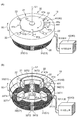
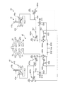
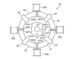
도 2는 도 1에 도시된 전동기의 제어 회로의 여자 회로부의 동작을 설명하기 위한 회로도이다.
도 3은 전동기의 동작을 설명하기위한 도면이며, (A)는 끝 부분이 N 극, 다른 쪽 끝 부분이 S 극을 발생하는 상태이고, 다이어그램 (B) 쪽 끝이 S 극, 다른 쪽 끝 부분이 N 극을 발생한 상태의 도면이다.
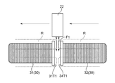
도 4는 도 1에 도시된 전동기의 회전자의 영구 자석과 고정자 권선 자력선의 상태를 설명하기 위한 도면이다.
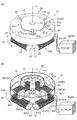
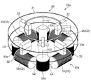
도 5는 본 발명의 실시 예 2에 따른 회전 전기로 모터를 설명하기 위한 도면이며, (A)는 전동기의 사시도, (B)는 하우징 및 차폐판을 투과한 상태의 전동기의 사시도이다.
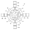
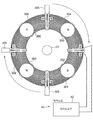
도 6은 본 발명의 실시 예 3에 따른 회전 전기로 모터를 설명하기 위한 도면이며, 회전자와 고정자와 센서부와 보조 권선을 나타낸 도면이다.
도 7은 도 6에 도시된 실시 예 3에 따른 전동기의 변형 예를 설명하기 위한 도면이다.
도 8은 본 발명의 실시 예 4에 따른 회전 전기로 모터를 설명하기 위한 도면이며, 회전자와 고정자와 센서부와 보조 권선과 발전용 권선을 나타내는 도면이다.
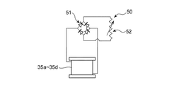
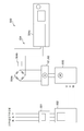
도 9는 도 8에 도시된 전동기의 발전용 권선에 연결된 회전 속도 조정부를 설명하기 위한 회로도이다.
도 10은 도 9에 나타낸 실시 예 4에 따른 전동기의 변형 예를 설명하기 위한 도면이다.
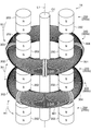
도 11은 본 발명의 실시 예 5에 따른 회전 전기로 모터를 설명하기 위한 사시도이다.
도 12는 도 11에 도시된 전동기의 고정자 권선을 휘감는 코어의 도면이다.
도 13은 도 11에 도시된 전동기의 동작을 설명하기 위한 사시도이다.
도 14는 도 13에 도시된 전동기의 상단의 고정자 및 그 고정자와 마주보는 상단 영구 자석의 도면이다.
도 15는 도 13에 도시된 전동기가 45도 회전 한 상태의 사시도이다.
도 16은 도 15에 도시된 전동기의 상단의 고정자 및 그 고정자와 마주 상단 및 중간 영구 자석의 도면이다.
도 17은 본 발명의 실시 예 6에 따른 회전 전기로 모터를 설명하기 위한 사시도이다.
도 18은 도 5에 도시된 전동기의 고정자를 단면 타원형의 권선으로 한 것이며, 고정자를 사이에 두고 반대편에 회전자를 마련한 전동기의 도면이다.
도 19는 본 실시 예의 발전기와 비교품의 발전기의 발전 전력을 측정하기 위한 측정 시스템의 구성을 나타내는 도면이다.
도 20은 도 19에 도시된 측정 시스템에 의해 측정된 입력 전력에 대한 발전 전력의 표이다.
도 21은 도 20의 표에 나타낸 각 값을 그래프로 나타낸 도면이다.
20,200 회전자 200a 제 1 회전자
200b 제 2 회전자 200c 제 3 회전자
21 하우징 22,202 영구 자석
30,30a,30b,300,320 고정자
300a 제 1 고정자 300b 제 2 고정자
301~304 권선 310 코어
311 차양부 312 심재
305 연결선
31~34 제1 권선~ 제4 권선
31T1,31T2,32T1,32T2,33T1,33T1,33T2,34T1,34T2 단부
33a~33d 권선 35a~35d 발전용 권선
40 제어 회로 41 센서부
411 제 1 센서 412 제 2 센서부
41a 후오토 인터 럽터 41b 차폐판
41c 원호 형상 홈부 42 여자 회로부
421a, 421b 제 1FET 422a, 422b 제 2FET
423a, 423b 제 3FET G 게이트 단자
S 소스 단자 D 드레인 단자
R11, R12, R21, R22, R31, R32, R41, R42 저항
C11, C12 콘덴서
D11, D12, D21, D22 다이오드
50 회전 속도 조정부 51 정류부
52 소비부 C1, C2, C3 권선
O1 출력축 R1 회전 원주
F1 주 자속 방향 L1 회전 축선
L2, L3 축선 R 자로
S1 틈새 G1 발전기(발명품)
G2 발전기(비교품) 500 측정 시스템
501 전력계 502 인버터
503 모터 504 부하부
504a 다이오드 브리지 504b 콘덴서
504c 전자 부하 장치
Claims (10)
- 복수의 영구 자석이 하우징에 회전 원주를 따라 배치되고, 상기 영구 자석의 자극이 회전 축선을 따른 방향으로 향한 회전자와,
회전 원주를 따라 배치된 복수의 권선을 갖는 고정자를 구비하고,
상기 권선은 상기 영구 자석의 자극이 상기 권선으로 향할 때, 상기 권선의 단부로부터 권선 내로의 자로가, 상기 영구 자석에서 주 자속 방향과 교차하는 방향으로 형성되어,
상기 고정자는 상기 회전자의 회전 축선을 따라 복수로 구비되고,
상기 고정자의 각각은 상기 고정자를 형성하는 권선끼리의 간격이 회전 원주 방향으로 어긋난 위치에 배치된 회전 전기. - 복수의 영구 자석이 하우징에 회전 원주를 따라 배치되고, 상기 영구 자석의 자극이 회전 축선을 따른 방향으로 향한 회전자와,
회전 원주를 따라 배치된 복수의 권선을 갖는 고정자를 구비하고,
상기 권선은 상기 영구 자석의 자극이 상기 권선으로 향할 때, 상기 권선의 단부로부터 권선 내에 자로가, 상기 영구 자석에서 주 자속 방향과 교차하는 방향으로 형성되어,
상기 복수의 권선 단부들 사이에 보조 권선이 설치된 회전 전기. - 청구항 1 또는 청구항 2에 있어서,
상기 회전자는 상기 고정자를 사이에 두고 양쪽에 배치된 회전 전기. - 청구항 1 내지 3 중 어느 한 항에 있어서,
상기 고정자는 상기 회전자의 회전 원주에 따른 원호 형상의 상기 권선에 의해 형성된 회전 전기. - 청구항 1 내지 3 중 어느 한 항에 있어서,
상기 고정자는 상기 회전자의 회전 원주의 접선을 따라 축선이 직선 형상의 상기 권선에 의해 형성된 회전 전기. - 청구항 1 내지 5 중 어느 한 항에 있어서,
상기 고정자는 상기 회전자의 회전 중심을 둘러싼 권선이 병렬 연결된 복수체에 의해 형성된 회전 전기. - 청구항 1 내지 6 중 어느 한 항에 있어서,
상기 권선의 단면은 회전 축선에 따른 방향의 길이가 회전 원주의 반경 방향의 길이보다 짧게 형성된 회전 전기. - 청구항 2에 있어서,
상기 보조 권선과 동축에 발전용 권선이 마련된 회전 전기. - 청구항 8에 있어서,
상기 발전용 권선의 전류를 조정하는 회전 속도 조정부가 연결되는 회전 전기. - 청구항 9에 있어서,
상기 회전 속도 조정부는 상기 발전용 권선에 연결된 정류부와, 상기 정류부에서 전류를 소비하는 소비부를 구비한 회전 전기.
Applications Claiming Priority (5)
| Application Number | Priority Date | Filing Date | Title |
|---|---|---|---|
| JPJP-P-2017-150676 | 2017-08-03 | ||
| JP2017150676 | 2017-08-03 | ||
| JPJP-P-2017-221198 | 2017-11-16 | ||
| JP2017221198A JP6359747B1 (ja) | 2017-08-03 | 2017-11-16 | 回転電機 |
| PCT/JP2018/027897 WO2019026725A1 (ja) | 2017-08-03 | 2018-07-25 | 回転電機 |
Publications (2)
| Publication Number | Publication Date |
|---|---|
| KR20200024294A true KR20200024294A (ko) | 2020-03-06 |
| KR102373398B1 KR102373398B1 (ko) | 2022-03-11 |
Family
ID=62904881
Family Applications (1)
| Application Number | Title | Priority Date | Filing Date |
|---|---|---|---|
| KR1020207003202A Expired - Fee Related KR102373398B1 (ko) | 2017-08-03 | 2018-07-25 | 회전 전기 |
Country Status (10)
| Country | Link |
|---|---|
| US (1) | US11482914B2 (ko) |
| EP (1) | EP3648320A4 (ko) |
| JP (1) | JP6359747B1 (ko) |
| KR (1) | KR102373398B1 (ko) |
| CN (2) | CN114465375A (ko) |
| AU (1) | AU2018309956B2 (ko) |
| CA (1) | CA3070354C (ko) |
| MY (1) | MY187170A (ko) |
| PH (1) | PH12020500229A1 (ko) |
| WO (1) | WO2019026725A1 (ko) |
Families Citing this family (2)
| Publication number | Priority date | Publication date | Assignee | Title |
|---|---|---|---|---|
| CN116568995B (zh) * | 2020-12-11 | 2024-09-06 | 马渊马达株式会社 | 旋转变压器 |
| WO2023075073A1 (en) * | 2021-10-26 | 2023-05-04 | Jei Hyun Goo | Apparatus for operating alternatively as dc (direct current) motor and dc generator |
Citations (9)
| Publication number | Priority date | Publication date | Assignee | Title |
|---|---|---|---|---|
| JPS60226751A (ja) | 1984-04-25 | 1985-11-12 | Matsushita Electric Ind Co Ltd | 永久磁石回転子型同期電動機 |
| JPH04208049A (ja) * | 1990-11-30 | 1992-07-29 | Fujitsu General Ltd | コンデンサ誘導電動機 |
| JP2000184627A (ja) | 1998-12-10 | 2000-06-30 | Minebea Co Ltd | トロイダルコア型アクチュエータ |
| US20040070307A1 (en) * | 2002-10-14 | 2004-04-15 | Deere & Company | Axial gap brushless DC motor |
| JP2006238625A (ja) * | 2005-02-25 | 2006-09-07 | Fujitsu General Ltd | 直流モータ |
| KR20110059805A (ko) * | 2008-11-10 | 2011-06-03 | 데쓰오 오카모토 | 발전기 |
| JP2013021888A (ja) * | 2011-07-14 | 2013-01-31 | Shinsei Shoji Co Ltd | 発電装置 |
| JP2014135852A (ja) | 2013-01-10 | 2014-07-24 | Asmo Co Ltd | ブラシレスモータ |
| JP2014147238A (ja) | 2013-01-30 | 2014-08-14 | Hitachi Appliances Inc | 電動機及びこの電動機を備えた流体圧縮機 |
Family Cites Families (11)
| Publication number | Priority date | Publication date | Assignee | Title |
|---|---|---|---|---|
| US6348751B1 (en) * | 1997-12-12 | 2002-02-19 | New Generation Motors Corporation | Electric motor with active hysteresis-based control of winding currents and/or having an efficient stator winding arrangement and/or adjustable air gap |
| US6509664B2 (en) * | 2000-01-13 | 2003-01-21 | General Electric Company | Hybrid synchronous machines comprising permanent magnets and excitation windings in cylindrical element slots |
| JP4784726B2 (ja) * | 2005-02-25 | 2011-10-05 | 株式会社富士通ゼネラル | 直流モータ |
| US20080067883A1 (en) * | 2006-09-18 | 2008-03-20 | Witt Peter D | Generator and/or motor assembly |
| JP4926107B2 (ja) * | 2008-03-28 | 2012-05-09 | 株式会社豊田中央研究所 | 回転電機 |
| US8049389B2 (en) * | 2008-06-02 | 2011-11-01 | Honda Motor Co., Ltd. | Axial gap motor |
| JP4309962B1 (ja) * | 2009-01-20 | 2009-08-05 | 哲夫 岡本 | 電動機 |
| TWI399012B (zh) * | 2010-11-12 | 2013-06-11 | Yen Sun Technology Corp | Motor stator |
| CN201956846U (zh) * | 2010-11-29 | 2011-08-31 | 余虹锦 | 一种新型结构的复合励磁无刷单相同步发电机 |
| KR101772271B1 (ko) * | 2015-06-03 | 2017-08-29 | 박태혁 | 역기전력 저감 발전장치 |
| JP2017005806A (ja) * | 2015-06-05 | 2017-01-05 | 株式会社インターナショナル電子 | 省エネ型モータ |
-
2017
- 2017-11-16 JP JP2017221198A patent/JP6359747B1/ja not_active Expired - Fee Related
-
2018
- 2018-07-25 CA CA3070354A patent/CA3070354C/en active Active
- 2018-07-25 CN CN202210131338.5A patent/CN114465375A/zh active Pending
- 2018-07-25 US US16/636,327 patent/US11482914B2/en active Active
- 2018-07-25 CN CN201880048429.4A patent/CN110945763B/zh not_active Expired - Fee Related
- 2018-07-25 AU AU2018309956A patent/AU2018309956B2/en not_active Ceased
- 2018-07-25 EP EP18842245.5A patent/EP3648320A4/en not_active Withdrawn
- 2018-07-25 MY MYPI2020000491A patent/MY187170A/en unknown
- 2018-07-25 WO PCT/JP2018/027897 patent/WO2019026725A1/ja not_active Ceased
- 2018-07-25 KR KR1020207003202A patent/KR102373398B1/ko not_active Expired - Fee Related
-
2020
- 2020-01-30 PH PH12020500229A patent/PH12020500229A1/en unknown
Patent Citations (9)
| Publication number | Priority date | Publication date | Assignee | Title |
|---|---|---|---|---|
| JPS60226751A (ja) | 1984-04-25 | 1985-11-12 | Matsushita Electric Ind Co Ltd | 永久磁石回転子型同期電動機 |
| JPH04208049A (ja) * | 1990-11-30 | 1992-07-29 | Fujitsu General Ltd | コンデンサ誘導電動機 |
| JP2000184627A (ja) | 1998-12-10 | 2000-06-30 | Minebea Co Ltd | トロイダルコア型アクチュエータ |
| US20040070307A1 (en) * | 2002-10-14 | 2004-04-15 | Deere & Company | Axial gap brushless DC motor |
| JP2006238625A (ja) * | 2005-02-25 | 2006-09-07 | Fujitsu General Ltd | 直流モータ |
| KR20110059805A (ko) * | 2008-11-10 | 2011-06-03 | 데쓰오 오카모토 | 발전기 |
| JP2013021888A (ja) * | 2011-07-14 | 2013-01-31 | Shinsei Shoji Co Ltd | 発電装置 |
| JP2014135852A (ja) | 2013-01-10 | 2014-07-24 | Asmo Co Ltd | ブラシレスモータ |
| JP2014147238A (ja) | 2013-01-30 | 2014-08-14 | Hitachi Appliances Inc | 電動機及びこの電動機を備えた流体圧縮機 |
Also Published As
| Publication number | Publication date |
|---|---|
| CN114465375A (zh) | 2022-05-10 |
| WO2019026725A1 (ja) | 2019-02-07 |
| CA3070354C (en) | 2022-08-23 |
| EP3648320A4 (en) | 2021-03-24 |
| AU2018309956B2 (en) | 2020-11-26 |
| PH12020500229A1 (en) | 2020-11-09 |
| AU2018309956A1 (en) | 2020-02-13 |
| CA3070354A1 (en) | 2019-02-07 |
| JP2019030202A (ja) | 2019-02-21 |
| CN110945763B (zh) | 2022-01-14 |
| JP6359747B1 (ja) | 2018-07-18 |
| CN110945763A (zh) | 2020-03-31 |
| EP3648320A1 (en) | 2020-05-06 |
| MY187170A (en) | 2021-09-07 |
| US20210028677A1 (en) | 2021-01-28 |
| US11482914B2 (en) | 2022-10-25 |
| KR102373398B1 (ko) | 2022-03-11 |
Similar Documents
| Publication | Publication Date | Title |
|---|---|---|
| US11979072B2 (en) | Magnetic geared motor | |
| JP5449892B2 (ja) | 永久磁石励磁式ラジアル磁気軸受並びにそのラジアル磁気軸受を備えた磁気軸受装置 | |
| JP2832307B2 (ja) | 電動機 | |
| JP2010025342A6 (ja) | 永久磁石励磁式ラジアル磁気軸受並びにそのラジアル磁気軸受を備えた磁気軸受装置 | |
| JP2021182865A (ja) | 電動モータ | |
| KR102051115B1 (ko) | 전동기 | |
| WO2017033570A1 (ja) | 磁気浮上姿勢制御装置 | |
| AU2010330123A1 (en) | Electric machine | |
| KR20170024744A (ko) | 고효율 직류 전동기 및 그 제어방법 | |
| KR102373398B1 (ko) | 회전 전기 | |
| CN104767336A (zh) | 一种单相他励磁阻式发电机 | |
| US20150022043A1 (en) | Electric motor | |
| US20160352204A1 (en) | Refrigeration apparatus | |
| JP6766574B2 (ja) | 回転電機 | |
| US10931183B2 (en) | Asynchronous machine | |
| JP2019110752A (ja) | 管状コイルとそれを用いたモータおよび発電機 | |
| US7459824B2 (en) | High torque repulsion motor | |
| CN203674938U (zh) | 同步电动机 | |
| RU124457U1 (ru) | Синхронная электрическая машина с осевым магнитным потоком | |
| JP5795170B2 (ja) | 発電システム | |
| CN109075680A (zh) | 旋转发电机 | |
| US11863016B2 (en) | Electric motor | |
| CN211579844U (zh) | 电动装置和电动泵 | |
| JP6243073B1 (ja) | 回転電機 | |
| JP2024018485A (ja) | 回転電機 |
Legal Events
| Date | Code | Title | Description |
|---|---|---|---|
| A201 | Request for examination | ||
| P11-X000 | Amendment of application requested |
St.27 status event code: A-2-2-P10-P11-nap-X000 |
|
| P13-X000 | Application amended |
St.27 status event code: A-2-2-P10-P13-nap-X000 |
|
| PA0105 | International application |
St.27 status event code: A-0-1-A10-A15-nap-PA0105 |
|
| PA0201 | Request for examination |
St.27 status event code: A-1-2-D10-D11-exm-PA0201 |
|
| PG1501 | Laying open of application |
St.27 status event code: A-1-1-Q10-Q12-nap-PG1501 |
|
| D13-X000 | Search requested |
St.27 status event code: A-1-2-D10-D13-srh-X000 |
|
| D14-X000 | Search report completed |
St.27 status event code: A-1-2-D10-D14-srh-X000 |
|
| E902 | Notification of reason for refusal | ||
| PE0902 | Notice of grounds for rejection |
St.27 status event code: A-1-2-D10-D21-exm-PE0902 |
|
| P11-X000 | Amendment of application requested |
St.27 status event code: A-2-2-P10-P11-nap-X000 |
|
| P13-X000 | Application amended |
St.27 status event code: A-2-2-P10-P13-nap-X000 |
|
| E701 | Decision to grant or registration of patent right | ||
| PE0701 | Decision of registration |
St.27 status event code: A-1-2-D10-D22-exm-PE0701 |
|
| GRNT | Written decision to grant | ||
| PR0701 | Registration of establishment |
St.27 status event code: A-2-4-F10-F11-exm-PR0701 |
|
| PR1002 | Payment of registration fee |
St.27 status event code: A-2-2-U10-U12-oth-PR1002 Fee payment year number: 1 |
|
| PG1601 | Publication of registration |
St.27 status event code: A-4-4-Q10-Q13-nap-PG1601 |
|
| P22-X000 | Classification modified |
St.27 status event code: A-4-4-P10-P22-nap-X000 |
|
| PC1903 | Unpaid annual fee |
St.27 status event code: A-4-4-U10-U13-oth-PC1903 Not in force date: 20250308 Payment event data comment text: Termination Category : DEFAULT_OF_REGISTRATION_FEE |
|
| H13 | Ip right lapsed |
Free format text: ST27 STATUS EVENT CODE: N-4-6-H10-H13-OTH-PC1903 (AS PROVIDED BY THE NATIONAL OFFICE); TERMINATION CATEGORY : DEFAULT_OF_REGISTRATION_FEE Effective date: 20250308 |
|
| PC1903 | Unpaid annual fee |
St.27 status event code: N-4-6-H10-H13-oth-PC1903 Ip right cessation event data comment text: Termination Category : DEFAULT_OF_REGISTRATION_FEE Not in force date: 20250308 |