KR20200024902A - Jaw assembly for vascular suture - Google Patents
Jaw assembly for vascular suture Download PDFInfo
- Publication number
- KR20200024902A KR20200024902A KR1020207003204A KR20207003204A KR20200024902A KR 20200024902 A KR20200024902 A KR 20200024902A KR 1020207003204 A KR1020207003204 A KR 1020207003204A KR 20207003204 A KR20207003204 A KR 20207003204A KR 20200024902 A KR20200024902 A KR 20200024902A
- Authority
- KR
- South Korea
- Prior art keywords
- jaw
- jaw assembly
- flange
- flanges
- assembly
- Prior art date
- Legal status (The legal status is an assumption and is not a legal conclusion. Google has not performed a legal analysis and makes no representation as to the accuracy of the status listed.)
- Granted
Links
Images


Classifications
-
- A—HUMAN NECESSITIES
- A61—MEDICAL OR VETERINARY SCIENCE; HYGIENE
- A61B—DIAGNOSIS; SURGERY; IDENTIFICATION
- A61B17/00—Surgical instruments, devices or methods
- A61B17/28—Surgical forceps
- A61B17/2812—Surgical forceps with a single pivotal connection
- A61B17/282—Jaws
-
- A—HUMAN NECESSITIES
- A61—MEDICAL OR VETERINARY SCIENCE; HYGIENE
- A61B—DIAGNOSIS; SURGERY; IDENTIFICATION
- A61B17/00—Surgical instruments, devices or methods
- A61B17/28—Surgical forceps
- A61B17/29—Forceps for use in minimally invasive surgery
- A61B17/295—Forceps for use in minimally invasive surgery combined with cutting implements
-
- A—HUMAN NECESSITIES
- A61—MEDICAL OR VETERINARY SCIENCE; HYGIENE
- A61B—DIAGNOSIS; SURGERY; IDENTIFICATION
- A61B17/00—Surgical instruments, devices or methods
- A61B17/22—Implements for squeezing-off ulcers or the like on inner organs of the body; Implements for scraping-out cavities of body organs, e.g. bones; for invasive removal or destruction of calculus using mechanical vibrations; for removing obstructions in blood vessels, not otherwise provided for
- A61B17/22031—Gripping instruments, e.g. forceps, for removing or smashing calculi
-
- A—HUMAN NECESSITIES
- A61—MEDICAL OR VETERINARY SCIENCE; HYGIENE
- A61B—DIAGNOSIS; SURGERY; IDENTIFICATION
- A61B18/00—Surgical instruments, devices or methods for transferring non-mechanical forms of energy to or from the body
- A61B18/04—Surgical instruments, devices or methods for transferring non-mechanical forms of energy to or from the body by heating
- A61B18/12—Surgical instruments, devices or methods for transferring non-mechanical forms of energy to or from the body by heating by passing a current through the tissue to be heated, e.g. high-frequency current
- A61B18/14—Probes or electrodes therefor
- A61B18/1442—Probes having pivoting end effectors, e.g. forceps
- A61B18/1445—Probes having pivoting end effectors, e.g. forceps at the distal end of a shaft, e.g. forceps or scissors at the end of a rigid rod
-
- A—HUMAN NECESSITIES
- A61—MEDICAL OR VETERINARY SCIENCE; HYGIENE
- A61B—DIAGNOSIS; SURGERY; IDENTIFICATION
- A61B17/00—Surgical instruments, devices or methods
- A61B17/11—Surgical instruments, devices or methods for performing anastomosis; Buttons for anastomosis
- A61B2017/1107—Surgical instruments, devices or methods for performing anastomosis; Buttons for anastomosis for blood vessels
-
- A—HUMAN NECESSITIES
- A61—MEDICAL OR VETERINARY SCIENCE; HYGIENE
- A61B—DIAGNOSIS; SURGERY; IDENTIFICATION
- A61B17/00—Surgical instruments, devices or methods
- A61B17/28—Surgical forceps
- A61B17/29—Forceps for use in minimally invasive surgery
- A61B2017/2901—Details of shaft
- A61B2017/2906—Multiple forceps
-
- A—HUMAN NECESSITIES
- A61—MEDICAL OR VETERINARY SCIENCE; HYGIENE
- A61B—DIAGNOSIS; SURGERY; IDENTIFICATION
- A61B17/00—Surgical instruments, devices or methods
- A61B17/28—Surgical forceps
- A61B17/29—Forceps for use in minimally invasive surgery
- A61B17/2909—Handles
- A61B2017/2912—Handles transmission of forces to actuating rod or piston
- A61B2017/2919—Handles transmission of forces to actuating rod or piston details of linkages or pivot points
-
- A—HUMAN NECESSITIES
- A61—MEDICAL OR VETERINARY SCIENCE; HYGIENE
- A61B—DIAGNOSIS; SURGERY; IDENTIFICATION
- A61B17/00—Surgical instruments, devices or methods
- A61B17/28—Surgical forceps
- A61B17/29—Forceps for use in minimally invasive surgery
- A61B2017/2926—Details of heads or jaws
- A61B2017/2932—Transmission of forces to jaw members
-
- A—HUMAN NECESSITIES
- A61—MEDICAL OR VETERINARY SCIENCE; HYGIENE
- A61B—DIAGNOSIS; SURGERY; IDENTIFICATION
- A61B18/00—Surgical instruments, devices or methods for transferring non-mechanical forms of energy to or from the body
- A61B2018/00571—Surgical instruments, devices or methods for transferring non-mechanical forms of energy to or from the body for achieving a particular surgical effect
- A61B2018/00601—Cutting
-
- A—HUMAN NECESSITIES
- A61—MEDICAL OR VETERINARY SCIENCE; HYGIENE
- A61B—DIAGNOSIS; SURGERY; IDENTIFICATION
- A61B18/00—Surgical instruments, devices or methods for transferring non-mechanical forms of energy to or from the body
- A61B2018/00571—Surgical instruments, devices or methods for transferring non-mechanical forms of energy to or from the body for achieving a particular surgical effect
- A61B2018/00607—Coagulation and cutting with the same instrument
-
- A—HUMAN NECESSITIES
- A61—MEDICAL OR VETERINARY SCIENCE; HYGIENE
- A61B—DIAGNOSIS; SURGERY; IDENTIFICATION
- A61B18/00—Surgical instruments, devices or methods for transferring non-mechanical forms of energy to or from the body
- A61B2018/00571—Surgical instruments, devices or methods for transferring non-mechanical forms of energy to or from the body for achieving a particular surgical effect
- A61B2018/0063—Sealing
-
- A—HUMAN NECESSITIES
- A61—MEDICAL OR VETERINARY SCIENCE; HYGIENE
- A61B—DIAGNOSIS; SURGERY; IDENTIFICATION
- A61B18/00—Surgical instruments, devices or methods for transferring non-mechanical forms of energy to or from the body
- A61B18/04—Surgical instruments, devices or methods for transferring non-mechanical forms of energy to or from the body by heating
- A61B18/12—Surgical instruments, devices or methods for transferring non-mechanical forms of energy to or from the body by heating by passing a current through the tissue to be heated, e.g. high-frequency current
- A61B18/14—Probes or electrodes therefor
- A61B2018/1405—Electrodes having a specific shape
- A61B2018/1412—Blade
-
- A—HUMAN NECESSITIES
- A61—MEDICAL OR VETERINARY SCIENCE; HYGIENE
- A61B—DIAGNOSIS; SURGERY; IDENTIFICATION
- A61B18/00—Surgical instruments, devices or methods for transferring non-mechanical forms of energy to or from the body
- A61B18/04—Surgical instruments, devices or methods for transferring non-mechanical forms of energy to or from the body by heating
- A61B18/12—Surgical instruments, devices or methods for transferring non-mechanical forms of energy to or from the body by heating by passing a current through the tissue to be heated, e.g. high-frequency current
- A61B18/14—Probes or electrodes therefor
- A61B2018/1405—Electrodes having a specific shape
- A61B2018/1425—Needle
- A61B2018/1432—Needle curved
-
- A—HUMAN NECESSITIES
- A61—MEDICAL OR VETERINARY SCIENCE; HYGIENE
- A61B—DIAGNOSIS; SURGERY; IDENTIFICATION
- A61B18/00—Surgical instruments, devices or methods for transferring non-mechanical forms of energy to or from the body
- A61B18/04—Surgical instruments, devices or methods for transferring non-mechanical forms of energy to or from the body by heating
- A61B18/12—Surgical instruments, devices or methods for transferring non-mechanical forms of energy to or from the body by heating by passing a current through the tissue to be heated, e.g. high-frequency current
- A61B18/14—Probes or electrodes therefor
- A61B18/1442—Probes having pivoting end effectors, e.g. forceps
- A61B2018/1452—Probes having pivoting end effectors, e.g. forceps including means for cutting
- A61B2018/1455—Probes having pivoting end effectors, e.g. forceps including means for cutting having a moving blade for cutting tissue grasped by the jaws
Landscapes
- Health & Medical Sciences (AREA)
- Surgery (AREA)
- Life Sciences & Earth Sciences (AREA)
- Engineering & Computer Science (AREA)
- Molecular Biology (AREA)
- Public Health (AREA)
- Veterinary Medicine (AREA)
- Biomedical Technology (AREA)
- Heart & Thoracic Surgery (AREA)
- Medical Informatics (AREA)
- Nuclear Medicine, Radiotherapy & Molecular Imaging (AREA)
- Animal Behavior & Ethology (AREA)
- General Health & Medical Sciences (AREA)
- Ophthalmology & Optometry (AREA)
- Orthopedic Medicine & Surgery (AREA)
- Vascular Medicine (AREA)
- Physics & Mathematics (AREA)
- Plasma & Fusion (AREA)
- Otolaryngology (AREA)
- Surgical Instruments (AREA)
- Closing Of Containers (AREA)
Abstract
죠 부재들(jaw members) 중 하나와 관련된 두개의 플랜지들(flanges) 및 죠 부재들 중 다른 하나(other)와 관련된 단일 중심에(centrally) 위치된 플랜지를 통해 함께 피봇식(pivotally)으로 결합된 한 쌍의 죠 부재를 가지는 혈관 봉합 장치(vessel sealing device)를 위한 죠 조립체(jaw assembly). 플랜지들은 구동 샤프트(drive shaft)의 축 방향(axial) 이동(movement)이 죠 부재들을 오픈(open) 및 클로즈(close) 할 수 있도록 캠 슬롯들(cam slots)을 포함한다. 중심 플랜지의 일 측에 위치되고, 그러므로 죠들의 중심 축으로부터 오프셋(offset)된 나이프 블레이드(knife blade)의 축 방향 이동을 위한 나이프 통로(pathway)를 죠 부재들이 포함할 수 있다.Pivotally joined together through two flanges associated with one of the jaw members and a flange located centrally relative to the other of the jaw members. Jaw assembly for vessel sealing device having a pair of jaw members. The flanges include cam slots such that the axial movement of the drive shaft can open and close the jaw members. The jaw members may comprise a knife path located on one side of the center flange and therefore for axial movement of a knife blade offset from the center axis of the jaws.
Description
본 출원은 2017년 7월 11일에 출원된 미국 우선권 특허 출원 번호 15/646,274의 우선권 및 이익을 주장한다.This application claims the priority and benefit of US Priority Patent Application No. 15 / 646,274, filed July 11, 2017.
본 발명은 전기수술(electrosurgical) 혈관 봉합기들(sealers) 및, 보다 구체적으로는, 플랜지들(flanges)의 상이한 숫자들을 가지는 죠 부재들(jaw members)로부터 형성된 힌지된(hinged) 죠 조립체와 관련이 있다. The present invention relates to a hinged jaw assembly formed from electrosurgical vascular sealers and, more particularly, jaw members having different numbers of flanges. There is this.
전기수술 혈관 봉합기들은 수술 절차들 동안 혈관들의 폐색(occlusion) 및 출혈(bleeding)의 정지(halting)를 위해 사용된다. 혈관 봉합기의 죠들은 죠들 사이에 클램프(clamped)되어 있는 혈관의 봉합(sealing) 및 건조를 위해 무선주파수(radiofrequency)(RF) 에너지를 죠들에 선택적으로 공급할 수 있는 전기수술 발전기(generator)에 상호 연결되어(interconnected) 있다. 블레이드(blade)는 통전된(energized) 죠들에 의해 생성된 봉합(seal)의 중간(intermediate) 부분을 따라 봉합된 혈관의 절단(cutting)을 위해 죠들에 추가로 통합될(incorporated) 수 있다.Electrosurgical vascular sutures are used for occlusion and halting of blood vessels during surgical procedures. The jaws of the vascular sutures are interconnected to an electrosurgical generator that can selectively supply radiofrequency (RF) energy to the jaws for sealing and drying the vessels clamped between the jaws. Are connected. The blade may be further incorporated in the jaws for cutting of the closed vessel along the intermediate portion of the seal created by energized jaws.
종래의(conventional) 혈관 봉합기들은 두개의 죠 부재들로부터 형성된 죠들을 가지며, 죠 부재들(which)의 각각은 죠들이 핸들(handle)의 사용자 작동(actuation)에 응답하여 자르도록(scissor) 공통(common) 힌지 핀에 연결된 플랜지를 가진다. 그러나, 이러한 구조적 배치는 사용자 손 피로 및 비효율적인 클램핑(clamping)을 야기하는(lead to) 불균형한 힘 및 에너지의 손실로 인해 기계적으로 비효율적이다. 이 문제를 해결하기 위한 현재의 접근법들(approaches)은 같이(together) 중첩(nested)되어야 하는 양쪽(both) 죠 부재들 상에 이중 힌지들을 사용하며, 그렇게 함으로써(thereby) 전기수술 공급 와이어(wires)들 및 절단(cutting) 블레이드와 같은 구성요소들(elements)을 위하여 달리(otherwise) 요구(required)되는 상당한(significant) 양의 공간(space)의 사용을 요구한다. 따라서, 죠들의 힌징(hinging)에 요구되는 공간의 양(amount of space)을 최적화(optimizing)하면서 효율적인 기계적 클램핑을 제공하는 혈관 봉합기 죠 부재들의 개선된(improved) 힌지의 필요가 있다.Conventional vascular sutures have jaws formed from two jaw members, each of which is common to allow the jaws to be cut in response to the user actuation of the handle. (common) has a flange connected to the hinge pin. However, this structural arrangement is mechanically inefficient due to unbalanced loss of force and energy which leads to user hand fatigue and inefficient clamping. Current approaches to solve this problem use double hinges on both jaw members that must be nested and thereby electrosurgical supply wires. And use of a significant amount of space that is otherwise required for elements such as cutting blades and cutting blades. Therefore, there is a need for improved hinges of vessel suture jaw members that provide efficient mechanical clamping while optimizing the amount of space required for the hinges of the jaws.
본 발명은 감소된 양의 공간에서 개선된 기계적 안정성을 가지는 혈관 봉합 장치(device)를 위한 죠 조립체이다. 죠 조립체는 제1 및 제2 이격 분리된(spaced apart) 플랜지들을 갖는 제1 죠 부재, 제1 죠 부재의 제1 및 제2 플랜지들 사이에 위치되고 제1 및 제2 플랜지들에 피봇식(pivotally)으로 연결된 단일의 제3 플랜지를 갖는 제2죠 부재를 갖는다. 죠 조립체는 제1 및 제2 캠 슬롯들(cam slots)과 제1 및 제2 죠 부재들 안에서 및 제3 플랜지에서 제3 캠 슬롯이 결합된 클레비스(clevis)와 함께 구동 샤프트(drive shaft)를 더 포함할 수 있다. 제1 죠 부재 및 제2 죠 부재는 피봇 핀에 의해 피봇식으로 연결되고, 피봇 핀은 제2 죠 부재의 제3 플랜지와 인접한 관계로(in abutting relation to) 위치되는 숄더(shoulder)를 가질 수 있다. 제1 및 제2 죠 부재들은 나이프 경로(knife pathway)를 정의하는 대응하는 제1 및 제2 슬롯들(slots)을 포함할 수 있고, 나이프 블레이드는 구동 샤프트로부터 단일 제3 플랜지의 일 측으로 연장할 수 있다. 나이프 경로는 단일 제3 플랜지의 일 측을 죠들의 단부(end)쪽으로 만곡(curve)할 수 있다. 외부 샤프트(outer shaft)는 구동 샤프트를 둘러싸고 피봇 핀을 지지할 수 있다. 제1 및 제2 와이어(wires)들은 제1 및 제2 죠 부재들에 의해 지지되는 제1 및 제2 전도성(conductive) 면(faces)에 결합하기 위해 외부 샤프트 및 제1 및 제2 플랜지들 중 하나 사이에서 연장할 수 있다. The present invention is a jaw assembly for a vascular closure device having improved mechanical stability in a reduced amount of space. The jaw assembly is located between the first jaw member having first and second spaced apart flanges, between the first and second flanges of the first jaw member and pivoted to the first and second flanges. and a second jaw member having a single third flange pivotally connected. The jaw assembly comprises a drive shaft with clevis combined with first and second cam slots and a third cam slot in the first and second jaw members and at the third flange. It may further include. The first jaw member and the second jaw member may be pivotally connected by a pivot pin, the pivot pin having a shoulder positioned in abutting relation to the third flange of the second jaw member. have. The first and second jaw members may include corresponding first and second slots that define a knife pathway, the knife blade extending from the drive shaft to one side of a single third flange. Can be. The knife path may curve one side of the single third flange toward the end of the jaws. An outer shaft can surround the drive shaft and support the pivot pin. The first and second wires of the outer shaft and the first and second flanges for coupling to the first and second conductive faces supported by the first and second jaw members. It can extend between one.
본 발명은 참조 도면들(accompanying drawings)과 함께 다음의 상세한 설명을 읽음으로써 더 충분히(fully) 이해되고 인식될 것이다:
도 1은 본 발명에 따른 힌지된(hinged) 죠들을 가지는 혈관 봉합 시스템(vessel sealing system)의 사시도(perspective view)이다.
도 2는 본 발명에 따른 혈관 봉합 시스템을 위한 힌지된 죠의 사시도이다; 및
도 3은 본 발명에 따른 혈관 봉합 시스템을 위한 힌지된 죠의 분해도(exploded view)이다.
도 4는 본 발명에 따른 혈관 봉합 시스템을 위한 힌지된 죠의 평면(top plan)이다; 및
도 5는 본 발명에 따른 혈관 봉합 시스템을 위한 힌지된 죠의 단면(cross-section)이다.The invention will be more fully understood and appreciated by reading the following detailed description in conjunction with the accompanying drawings:
1 is a perspective view of a vessel sealing system with hinged jaws in accordance with the present invention.
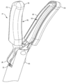
2 is a perspective view of a hinged jaw for a vascular closure system according to the present invention; And
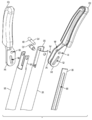
3 is an exploded view of a hinged jaw for a vascular closure system according to the present invention.
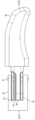
4 is a top plan of a hinged jaw for a vascular closure system according to the present invention; And
5 is a cross-section of a hinged jaw for a vascular closure system according to the present invention.
도면들 안에서(wherein) 전체에 걸쳐(throughout) 같은(like) 부분들을 같은 참조 번호들(numerals)로 지칭하는 도면들을 참조하면, 도 1에 보여지는 죠들(14) 사이에 트랩된(trapped) 혈관의 건조를 위해 죠들(14)에 RF 에너지를 공급할 수 있는 전기수술 발전기(16)에 상호 연결된 죠들(14)을 가지는 혈관 봉합기(12)를 포함하는 혈관 봉합 시스템(10)이 있다. 죠들(14)은 봉합기(12)의 핸들(18)을 조작하는(operating) 사용자에 응답하여 오픈(open) 및 클로즈(closed)되어지도록 힌지된다.Reference is made to the drawings, which refer to like parts throughout the figures with like numerals, where blood vessels are trapped between the
도 2에 보여지는 바와 같이, 죠들(14)은 두개의 대향하는(opposing) 죠 부재들(20, 22)로 구성된다. 죠 부재들(20, 22)은 나머지 죠들(14) 및 봉합기(10)로부터 전기적으로 분리되고(isolated) 전기수술 발전기(generator)(16)에 상호 연결된(interconnected) 내부(inner) 전도성 면들(24, 26)을 포함한다. 내부 전도성 면들(24, 26)은 내부 전도성 면들을 통해서(therethrough that) 형성되는 슬롯들(28, 30)을 가지며, 죠 부재들(20, 22)이 클로즈되는 경우, 죠들(they)이 통전되는 경우 죠들(14) 사이에 조직이 건조되는 영역을 교차하는(intersection) 나이프 경로를 정의하도록, 슬롯들이 정렬된다. 도 2 및 도 3에서 보여지는 바와 같이, 슬롯들(28, 30)에 의해 정의된 나이프 경로 및 죠들(14)은 사용 동안 표적 조직의 가시성(visibility)을 향상시키기 위해 한 방향으로 만곡될 수 있고, 따라서 오픈 수술 절차들 동안 개선된 유틸리티(utility)를 가능하게 한다(provide for).As shown in FIG. 2, the
도 3을 참조하면, 죠 부재들(20, 22) 중 하나(죠 부재(22)로 도시되나 대신에 죠 부재(20) 일 수 있다)는 이격 분리된 이중(dual) 힌지 플랜지들(32, 34)을 포함한다. 다른 죠 부재들(20, 22)(죠 부재(20)로 도시되나 대신에 죠 부재(22) 일 수 있다)은 이중 힌지 플랜지들(32, 34) 사이 및 죠들(14)의 축 X-X를 따라 중심으로(centrally) 위치된 단일 힌지 플랜지(36)를 포함한다. 이중 힌지 플랜지들(32, 34)은 이중 힌지 플랜지들을 통해 형성된(formed therethrough) 두개의 대향하는 캠 슬롯들(cam slots)(40, 42) 뿐만 아니라 두개의 대향하는 피봇 홀들(holes)(44, 46)을 포함한다. 단일 플랜지(36)는 단일 플랜지를 통해 형성된(formed therethrough) 대응하는 단일 캠 슬롯(48) 및 대응하는 단일 피봇 홀(50)을 포함한다. 피봇 핀(52)은 봉합기(10)가 조립되는 경우 이중 힌지 플랜지들(32, 34)의 두개의 대향하는 피봇 홀들(44, 46) 뿐만 아니라 단일 피봇 홀(50)을 통해 연장한다. 피봇 핀(52)은 축 X-X를 따라 종방향으로(longitudinally) 연장하는 외부 샤프트(54)의 단부(end)에서 클레비스(58)에 위치(in position)에 고정된다. 대응하는 단면을 가지는 구동 샤프트(56)는 외부 샤프트(54) 내부로(therein) 이동을 위해 외부 샤프트(54) 내에 위치된다. 구동 샤프트(56)는 일 단부에 위치된 클레비스 핀(62) 및 클레비스(60)에 의해 이중 힌지 플랜지들(32, 34)의 대향하는 캠 슬롯들(40, 42) 및 단일 플랜지(36)의 캠 슬롯(48)에 결합된다. 이중 힌지 플랜지들(32, 34)의 캠 슬롯들(40, 42) 및 단일 플랜지(36)의 캠 슬롯(48)은 구동 샤프트(56)의 이동 및 죠들(14)의 종 방향 축 XX에 관하여 반대 각도를 따라 이중 힌지 플랜지들(32, 34) 및 단일 힌지 플랜지(36) 내에서 연장한다. 결과적으로, 축 X-X를 따라 구동 샤프트(56)의 축의(axial) 이동은 이중 힌지 플랜지들(32, 34) 및 단일 힌지 플랜지(36)가 반대 방향으로 피봇 핀(52)에 대하여 피봇하도록 유발(cause)할 것이며, 그렇게 함으로써 구동 샤프트(56)의 이동의 방향에 의존하여 오픈 또는 클로즈된 위치들로 죠들(14)을 구동한다. 도 3 및 도 5에서 보여지는 바와 같이, 피봇 핀(52)은 외부 샤프트(54) 내에 횡 방향(transverse) 이동을 제한(restrict)하기 위해 단일 플랜지(36)와 인접한 관계로 위치되는 숄더(shoulder)(68)를 포함할 수 있다. 이중 힌지 플랜지들(32, 34)들 사이에 단일 힌지 플랜지(42)의 포지셔닝(positioning)에 의해, 죠들(14)은 기계적으로 안정적이고 조직에 관해 클로즈되는(closed about) 경우 피봇 핀(52)에 대한 불균형한(unbalanced) 힘으로 인한 에너지 손실을 겪지 않는다. 이러한 기계적 안정성의 결과로서, 죠들(14)은 보다 기계적으로 효율적이며, 따라서 반복적으로 조직을 클램프(clamp)하기 위한 죠들(14)의 작동은 손 피로를 야기할 가능성이 적다.Referring to FIG. 3, one of the
기계적 절단 수술들(operations)을 위하여, 이동가능한 나이프 블레이드(64)는 구동 샤프트(56) 내에 위치 될 수 있고, RF 에너지로 건조 후 조직을 절단하기 위해 죠 부재들(20, 22)이 클로즈되는 경우, 슬롯들(32, 34)에 의해 정의된 나이프 경로를 따라 후퇴 및 연장될 수 있다. 나이프 블레이드(64)는, 나이프 블레이드(64)가 축 X-X를 따라 축 방향으로(axially) 및 나이프 경로를 통하여 구동될(driven) 수 있도록, 혈관 봉합기(10)가 조립되는 경우 피봇 핀(52) 및 캠 핀(62)이 배치될 수 있는 종 방향 슬롯(66)을 갖는다. 도 5를 참조하면, 나이프 블레이드(64)는 단일 플랜지(36)의 일 측에 위치되고, 나이프 블레이드는 따라서 종 방향 축 X-X에 대하여 중심을 벗어난다(off-center). 바람직하게는, 나이프 블레이드(64)가 단일 플랜지(36)의 다른 측으로 오프셋 되어진다면 슬롯들(32, 34)에 의해 정의된 나이프 경로를 따라 연장되는 경우 나이프 블레이드(64)가 더 완만한(gentler) 곡선(curve)을 통해 굽혀(bend)질 수 있도록 나이프 블레이드(64)는 죠들(14)에 제공된 임의의 곡률(curvature)의 외측(outer side)으로 오프셋(off-set)된다. 도5에 보여지는 바와 같이, 전기수술 발전기(16)는 발전기(16)가 RF 에너지를 죠 부재들(20, 22)에 제공할 수 있도록, 내부 전도성 면들(24, 26)에 개별적으로 결합하기 위하여 외부 샤프트(54)의 안쪽(inside)을 따라 연장하는 한 쌍의 와이어들(70, 72)에 의해 죠 부재들(20, 22)에 상호 연결될 수 있다.For mechanical cutting operations, the
혈관 봉합기(10)는 따라서 봉합될 혈관에 대하여 클램핑 죠들(14)에 의해 사용될 수 있고, 이중 힌지 플랜지들(32, 34) 및 단일 힌지 플랜지(36)의 사용에 의해 생성된 외부 샤프트(54) 안의 공간들 내에 쉽게(easily) 수용된(contained) 와이어들(70, 72)을 통해 전도성 면들(24, 26)에 전기수술 발전기로 에너지를 공급할 수 있다. 혈관의 건조(desiccation)가 완료된 후, 나이프 블레이드(64)는 잘려진(severed) 혈관의 단부가 봉합되어 유지되도록 건조된 영역(region) 내에 건조된 혈관을 잘라내기 위해 슬롯들(28, 30)에 의해 정의된 나이프 경로를 통해 연장되어 질 수 있다. 나이프 블레이드(64)의 중심에서 벗어난(off-center) 포지셔닝(positioning)은 나이프 블레이드(64)가 슬롯들(28, 30)에 의해 정의된 나이프 경로의 임의의 만곡된 부분을 따라 보다 쉽게 통과하는 것을 허용(allows)한다.
Claims (13)
제1 및 제2 이격 분리된(spaced apart) 플랜지들(flanges)을 가지는 제1 죠 부재(first jaw member);
상기 제1 죠 부재의 상기 제1 및 제2 플랜지들 사이에 위치되고 상기 제1 및 제2 플랜지들에(thereto) 피봇식(pivotally)으로 연결된 단일(single) 제3 플랜지를 가지는 제2 죠 부재
를 포함하는 죠 조립체.
In a jaw assembly for a vessel sealing device:
A first jaw member having first and second spaced apart flanges;
A second jaw member having a single third flange positioned between said first and second flanges of said first jaw member and pivotally connected to said first and second flanges;
Jaw assembly comprising a.
상기 제1 죠 부재 및 상기 제2 죠 부재에 결합된(coupled) 구동 샤프트(drive shaft)를 더 포함하는
죠 조립체.
The method of claim 1,
And a drive shaft coupled to the first jaw member and the second jaw member.
Jaw assembly.
상기 구동 샤프트는 클레비스(clevis)에 의해 상기 제1 죠 부재 및 상기 제2 죠 부재에 결합되는
죠 조립체.
The method of claim 2,
The drive shaft is coupled to the first jaw member and the second jaw member by clevis.
Jaw assembly.
상기 클레비스는 상기 제1 및 제2 플랜지들에서 대응하는 제1 및 제2 캠 슬롯들(cam slots)에 의해 상기 제1 및 제2 플랜지들과 결합되는
죠 조립체.
The method of claim 3,
The clevis is coupled with the first and second flanges by corresponding first and second cam slots in the first and second flanges.
Jaw assembly.
상기 클레비스는 상기 제3 플랜지에서 제3 캠 슬롯에 의해 상기 제3 플랜지에 결합되는
죠 조립체.
The method of claim 4, wherein
The clevis is coupled to the third flange by a third cam slot in the third flange.
Jaw assembly.
제1 죠 부재 및 상기 제2 죠 부재는 피봇 핀(pivot pin)에 의해 피봇식으로 연결되는
죠 조립체.
The method of claim 5,
The first jaw member and the second jaw member are pivotally connected by a pivot pin.
Jaw assembly.
상기 피봇 핀은 상기 제2 죠 부재의 상기 제3 플랜지와 인접한 관계로(in abutting relation to) 위치되는 숄더(shoulder)를 가지는
죠 조립체.
The method of claim 6,
The pivot pin has a shoulder positioned in abutting relation to the third flange of the second jaw member.
Jaw assembly.
상기 제1 및 제2 죠 부재들은 나이프 경로(knife pathway)를 정의하는(defining) 대응하는 제1 및 제2 슬롯들을 포함하는
죠 조립체.
The method of claim 7, wherein
The first and second jaw members include corresponding first and second slots defining a knife pathway.
Jaw assembly.
상기 구동 샤프트로부터 상기 단일 제3 플랜지의 일 측(one side)으로 연장하는 나이프 블레이드(blade)를 더 포함하는
죠 조립체.
The method of claim 8,
And a knife blade extending from the drive shaft to one side of the single third flange.
Jaw assembly.
상기 나이프 경로는 상기 단일 제3 플랜지의 일 측에 위치된 상기 나이프 경로의 제1 단부(first end)로부터 안쪽으로(inwardly) 만곡(curves)하는
죠 조립체.
The method of claim 9,
The knife path curves inwardly from a first end of the knife path located on one side of the single third flange.
Jaw assembly.
상기 구동 샤프트를 둘러싸고 상기 피봇 핀을 지지하는(supporting) 외부 샤프트(outer shaft)를 더 포함하는
죠 조립체.
The method of claim 10,
An outer shaft surrounding the drive shaft and supporting the pivot pin;
Jaw assembly.
상기 제1 및 제2 플랜지들 중 하나 및 상기 외부 샤프트 사이에서 연장하고, 제1 및 제2 전도성 면들(conductive faces)에 개별적으로 결합된 제1 및 제2 와이어들(wires)을 더 포함하는
죠 조립체.
The method of claim 11,
And further comprising first and second wires extending between one of the first and second flanges and the outer shaft and individually coupled to first and second conductive faces.
Jaw assembly.
상기 제1 및 제2 전도성 면들은 개별적으로 상기 제1 및 제2 죠 부재들에 의해 지지되고 상기 제1 및 제2 죠 부재들로부터 전기적으로(electrically) 분리되는(isolated)
죠 조립체.The method of claim 12,
The first and second conductive faces are individually supported by the first and second jaw members and are electrically isolated from the first and second jaw members.
Jaw assembly.
Applications Claiming Priority (3)
| Application Number | Priority Date | Filing Date | Title |
|---|---|---|---|
| US15/646,274 US12446909B2 (en) | 2017-07-11 | 2017-07-11 | Jaw assembly for a vessel sealer |
| US15/646,274 | 2017-07-11 | ||
| PCT/US2018/041368 WO2019014164A1 (en) | 2017-07-11 | 2018-07-10 | Jaw assembly for a vessel sealer |
Publications (2)
| Publication Number | Publication Date |
|---|---|
| KR20200024902A true KR20200024902A (en) | 2020-03-09 |
| KR102329958B1 KR102329958B1 (en) | 2021-11-24 |
Family
ID=63042119
Family Applications (1)
| Application Number | Title | Priority Date | Filing Date |
|---|---|---|---|
| KR1020207003204A Active KR102329958B1 (en) | 2017-07-11 | 2018-07-10 | Jaw Assemblies for Vascular Sutures |
Country Status (9)
| Country | Link |
|---|---|
| US (1) | US12446909B2 (en) |
| EP (1) | EP3651673B1 (en) |
| JP (1) | JP6956849B2 (en) |
| KR (1) | KR102329958B1 (en) |
| CN (1) | CN111182846A (en) |
| AU (1) | AU2018299971B2 (en) |
| CA (1) | CA3069666C (en) |
| ES (1) | ES2913248T3 (en) |
| WO (1) | WO2019014164A1 (en) |
Families Citing this family (26)
| Publication number | Priority date | Publication date | Assignee | Title |
|---|---|---|---|---|
| US10973517B2 (en) | 2015-11-13 | 2021-04-13 | Intuitive Surgical Operations, Inc. | Stapler with composite cardan and screw drive |
| US10863988B2 (en) | 2017-11-29 | 2020-12-15 | Intuitive Surgical Operations, Inc. | Surgical instrument with lockout mechanism |
| CN111989051B (en) | 2018-02-12 | 2024-09-24 | 直观外科手术操作公司 | Surgical instruments with locking mechanism |
| EP4338687B1 (en) | 2018-02-26 | 2026-05-06 | Intuitive Surgical Operations, Inc. | Surgical instrument with lockout mechanism |
| US12029473B2 (en) * | 2018-05-31 | 2024-07-09 | Intuitive Surgical Operations, Inc. | Surgical instruments having a jaw locking mechanism |
| EP3866702A4 (en) | 2018-10-19 | 2022-07-20 | Intuitive Surgical Operations, Inc. | SURGICAL ENDOSCOPIC PURSE-STRAP SUTURE DEVICE |
| JP7241178B2 (en) | 2018-12-21 | 2023-03-16 | インテュイティブ サージカル オペレーションズ, インコーポレイテッド | Surgical instrument with reinforced staple cartridge |
| WO2020131685A1 (en) | 2018-12-21 | 2020-06-25 | Intuitive Surgical Operations, Inc. | Surgical instruments with switches for deactivating and/or identifying stapler cartridges |
| WO2020131290A1 (en) | 2018-12-21 | 2020-06-25 | Intuitive Surgical Operations, Inc. | Articulation assemblies for surgical instruments |
| CN113194847A (en) | 2018-12-21 | 2021-07-30 | 直观外科手术操作公司 | Actuation mechanism for a surgical instrument |
| GB2582317B (en) * | 2019-03-19 | 2023-04-19 | Gyrus Medical Ltd | An end effector for a surgical instrument |
| CN114269268B (en) | 2019-03-29 | 2025-01-28 | 捷锐士阿希迈公司(以奥林巴斯美国外科技术名义) | Pliers with two-part drive rod |
| WO2020214258A1 (en) | 2019-04-15 | 2020-10-22 | Intuitive Surgical Operations, Inc. | Staple cartridge for a surgical instrument |
| US12011168B2 (en) | 2019-04-17 | 2024-06-18 | Intuitive Surgical Operations, Inc. | Surgical stapling instrument |
| CN119745453A (en) | 2019-05-31 | 2025-04-04 | 直观外科手术操作公司 | Staple cartridge for surgical instruments |
| US11786325B2 (en) | 2019-07-02 | 2023-10-17 | Intuitive Surgical Operations, Inc. | Remotely controlling a system using video |
| CN114502083A (en) | 2019-10-18 | 2022-05-13 | 直观外科手术操作公司 | Surgical instrument with adjustable jaws |
| WO2021141971A1 (en) | 2020-01-07 | 2021-07-15 | Intuitive Surgical Operations, Inc. | Surgical instruments for applying multiple clips |
| US11642129B2 (en) | 2020-01-15 | 2023-05-09 | Intuitive Surgical Operations, Inc. | Staple cartridge and drive member for surgical instrument |
| US11857213B2 (en) | 2020-08-28 | 2024-01-02 | Gyrus Acmi, Inc. | Forceps with hinged jaws and force distribution |
| US12185964B2 (en) * | 2020-09-10 | 2025-01-07 | Covidien Lp | End effector assemblies for surgical instruments such as for use in robotic surgical systems |
| US11925406B2 (en) | 2020-09-14 | 2024-03-12 | Covidien Lp | End effector assemblies for surgical instruments |
| US20220079662A1 (en) * | 2020-09-14 | 2022-03-17 | Covidien Lp | End effector assemblies for surgical instruments |
| WO2022150215A1 (en) | 2021-01-08 | 2022-07-14 | Intuitive Surgical Operations, Inc. | Surgical stapling instruments |
| EP4274492B1 (en) | 2021-01-08 | 2026-01-28 | Intuitive Surgical Operations, Inc. | Surgical instrument with linear and purse string suture staples |
| US20220280227A1 (en) * | 2021-03-02 | 2022-09-08 | Covidien Lp | End effector drive mechanisms for surgical instruments such as for use in robotic surgical systems |
Citations (5)
| Publication number | Priority date | Publication date | Assignee | Title |
|---|---|---|---|---|
| US20050222611A1 (en) * | 2004-03-31 | 2005-10-06 | Sutter Medizintechnik Gmbh | Bipolar double-hinged instrument |
| JP2007195982A (en) * | 2006-01-24 | 2007-08-09 | Sherwood Services Ag | Vascular sealers and dividers for large tissue structures |
| US20120259331A1 (en) * | 2011-04-05 | 2012-10-11 | Tyco Healthcare Group Lp. | Electrically-insulative hinge for electrosurgical jaw assembly, bipolar forceps including same, and methods of jaw-assembly alignment using fastened electrically-insulative hinge |
| US20130066318A1 (en) * | 2011-09-09 | 2013-03-14 | Tyco Healthcare Group Lp | Apparatus For Performing Electrosurgical Procedures Having A Spring Mechanism Associated With The Jaw Members |
| US20140257274A1 (en) * | 2013-03-11 | 2014-09-11 | Covidien Lp | Surgical instrument |
Family Cites Families (17)
| Publication number | Priority date | Publication date | Assignee | Title |
|---|---|---|---|---|
| US5626609A (en) * | 1990-10-05 | 1997-05-06 | United States Surgical Corporation | Endoscopic surgical instrument |
| US5433725A (en) * | 1991-12-13 | 1995-07-18 | Unisurge, Inc. | Hand-held surgical device and tools for use therewith, assembly and method |
| GB9209206D0 (en) | 1992-04-29 | 1992-06-17 | Hoskin William J | Blood vessel clamps |
| JP2000262534A (en) | 1999-03-17 | 2000-09-26 | Olympus Optical Co Ltd | Bipolar coagulating-dissectioning utensil |
| US8734443B2 (en) | 2006-01-24 | 2014-05-27 | Covidien Lp | Vessel sealer and divider for large tissue structures |
| US8439911B2 (en) | 2009-09-09 | 2013-05-14 | Coviden Lp | Compact jaw including through bore pivot pin |
| US8568412B2 (en) * | 2009-09-09 | 2013-10-29 | Covidien Lp | Apparatus and method of controlling cutting blade travel through the use of etched features |
| US8480671B2 (en) * | 2010-01-22 | 2013-07-09 | Covidien Lp | Compact jaw including split pivot pin |
| US20120232338A1 (en) * | 2011-02-11 | 2012-09-13 | Steve Livneh | Surgical instrument with detachable tip |
| US8939972B2 (en) | 2011-05-06 | 2015-01-27 | Covidien Lp | Surgical forceps |
| US8747434B2 (en) * | 2012-02-20 | 2014-06-10 | Covidien Lp | Knife deployment mechanisms for surgical forceps |
| US8968311B2 (en) | 2012-05-01 | 2015-03-03 | Covidien Lp | Surgical instrument with stamped double-flag jaws and actuation mechanism |
| US9301798B2 (en) * | 2012-07-19 | 2016-04-05 | Covidien Lp | Surgical forceps including reposable end effector assemblies |
| US9265566B2 (en) | 2012-10-16 | 2016-02-23 | Covidien Lp | Surgical instrument |
| US10058343B2 (en) * | 2013-03-14 | 2018-08-28 | Covidien Lp | Systems for performing endoscopic procedures |
| WO2016045041A1 (en) | 2014-09-25 | 2016-03-31 | Covidien Lp | Surgical instruments facilitating replacement of disposable components and/or sterilization of reusable components |
| US10292759B2 (en) * | 2016-06-13 | 2019-05-21 | Gyrus Acmi, Inc. | Electrosurgical device for vessel sealing |
-
2017
- 2017-07-11 US US15/646,274 patent/US12446909B2/en active Active
-
2018
- 2018-07-10 EP EP18746808.7A patent/EP3651673B1/en active Active
- 2018-07-10 WO PCT/US2018/041368 patent/WO2019014164A1/en not_active Ceased
- 2018-07-10 ES ES18746808T patent/ES2913248T3/en active Active
- 2018-07-10 JP JP2020501336A patent/JP6956849B2/en active Active
- 2018-07-10 AU AU2018299971A patent/AU2018299971B2/en active Active
- 2018-07-10 CA CA3069666A patent/CA3069666C/en active Active
- 2018-07-10 KR KR1020207003204A patent/KR102329958B1/en active Active
- 2018-07-10 CN CN201880046793.7A patent/CN111182846A/en active Pending
Patent Citations (5)
| Publication number | Priority date | Publication date | Assignee | Title |
|---|---|---|---|---|
| US20050222611A1 (en) * | 2004-03-31 | 2005-10-06 | Sutter Medizintechnik Gmbh | Bipolar double-hinged instrument |
| JP2007195982A (en) * | 2006-01-24 | 2007-08-09 | Sherwood Services Ag | Vascular sealers and dividers for large tissue structures |
| US20120259331A1 (en) * | 2011-04-05 | 2012-10-11 | Tyco Healthcare Group Lp. | Electrically-insulative hinge for electrosurgical jaw assembly, bipolar forceps including same, and methods of jaw-assembly alignment using fastened electrically-insulative hinge |
| US20130066318A1 (en) * | 2011-09-09 | 2013-03-14 | Tyco Healthcare Group Lp | Apparatus For Performing Electrosurgical Procedures Having A Spring Mechanism Associated With The Jaw Members |
| US20140257274A1 (en) * | 2013-03-11 | 2014-09-11 | Covidien Lp | Surgical instrument |
Also Published As
| Publication number | Publication date |
|---|---|
| ES2913248T3 (en) | 2022-06-01 |
| EP3651673B1 (en) | 2022-03-30 |
| CA3069666A1 (en) | 2019-01-17 |
| JP2020526335A (en) | 2020-08-31 |
| US20190015124A1 (en) | 2019-01-17 |
| EP3651673A1 (en) | 2020-05-20 |
| JP6956849B2 (en) | 2021-11-02 |
| WO2019014164A1 (en) | 2019-01-17 |
| CN111182846A (en) | 2020-05-19 |
| AU2018299971A1 (en) | 2020-02-06 |
| AU2018299971B2 (en) | 2021-02-18 |
| WO2019014164A8 (en) | 2019-08-29 |
| KR102329958B1 (en) | 2021-11-24 |
| CA3069666C (en) | 2023-09-19 |
| US12446909B2 (en) | 2025-10-21 |
Similar Documents
| Publication | Publication Date | Title |
|---|---|---|
| KR102329958B1 (en) | Jaw Assemblies for Vascular Sutures | |
| ES2381939T3 (en) | Electrosurgical jaws with offset knife | |
| CN103381104B (en) | Operating forcepies | |
| EP0623316B1 (en) | Laparoscopic surgical instrument | |
| ES2391541T3 (en) | Vessel sealer and divider for large tissue structures | |
| US9192421B2 (en) | Blade lockout mechanism for surgical forceps | |
| US20170135751A1 (en) | Electrosurgical instrument and jaw part for same | |
| US9757138B2 (en) | Instrument with improved tool | |
| FI117087B (en) | Secateurs or other similar mowers | |
| CN112587228B (en) | Bipolar tissue closer | |
| US20190201031A1 (en) | Scissor forceps | |
| JP7168839B2 (en) | scissors forceps | |
| JP2005323723A (en) | Surgery apparatus | |
| JP7190033B6 (en) | scissors style vessel sealer | |
| JP7190033B2 (en) | scissors style vessel sealer | |
| CN117257439B (en) | A multi-station switching surgical instrument | |
| CN114286649A (en) | Force limiting mechanism for surgical instrument | |
| CN109223088A (en) | Vascular occlusion clamp for laparoscopic surgery | |
| RU2772893C1 (en) | Knotting unit |
Legal Events
| Date | Code | Title | Description |
|---|---|---|---|
| A201 | Request for examination | ||
| PA0105 | International application |
St.27 status event code: A-0-1-A10-A15-nap-PA0105 |
|
| PA0201 | Request for examination |
St.27 status event code: A-1-2-D10-D11-exm-PA0201 |
|
| PG1501 | Laying open of application |
St.27 status event code: A-1-1-Q10-Q12-nap-PG1501 |
|
| PE0902 | Notice of grounds for rejection |
St.27 status event code: A-1-2-D10-D21-exm-PE0902 |
|
| E13-X000 | Pre-grant limitation requested |
St.27 status event code: A-2-3-E10-E13-lim-X000 |
|
| P11-X000 | Amendment of application requested |
St.27 status event code: A-2-2-P10-P11-nap-X000 |
|
| P13-X000 | Application amended |
St.27 status event code: A-2-2-P10-P13-nap-X000 |
|
| E701 | Decision to grant or registration of patent right | ||
| PE0701 | Decision of registration |
St.27 status event code: A-1-2-D10-D22-exm-PE0701 |
|
| GRNT | Written decision to grant | ||
| PR0701 | Registration of establishment |
St.27 status event code: A-2-4-F10-F11-exm-PR0701 |
|
| PR1002 | Payment of registration fee |
St.27 status event code: A-2-2-U10-U12-oth-PR1002 Fee payment year number: 1 |
|
| PG1601 | Publication of registration |
St.27 status event code: A-4-4-Q10-Q13-nap-PG1601 |
|
| R18-X000 | Changes to party contact information recorded |
St.27 status event code: A-5-5-R10-R18-oth-X000 |
|
| PR1001 | Payment of annual fee |
St.27 status event code: A-4-4-U10-U11-oth-PR1001 Fee payment year number: 4 |
|
| PR1001 | Payment of annual fee |
St.27 status event code: A-4-4-U10-U11-oth-PR1001 Fee payment year number: 5 |
|
| U11 | Full renewal or maintenance fee paid |
Free format text: ST27 STATUS EVENT CODE: A-4-4-U10-U11-OTH-PR1001 (AS PROVIDED BY THE NATIONAL OFFICE) Year of fee payment: 5 |