KR20200037814A - Axial thrust balancing device - Google Patents
Axial thrust balancing device Download PDFInfo
- Publication number
- KR20200037814A KR20200037814A KR1020207005539A KR20207005539A KR20200037814A KR 20200037814 A KR20200037814 A KR 20200037814A KR 1020207005539 A KR1020207005539 A KR 1020207005539A KR 20207005539 A KR20207005539 A KR 20207005539A KR 20200037814 A KR20200037814 A KR 20200037814A
- Authority
- KR
- South Korea
- Prior art keywords
- thrust
- segment
- axial
- section
- shaft
- Prior art date
- Legal status (The legal status is an assumption and is not a legal conclusion. Google has not performed a legal analysis and makes no representation as to the accuracy of the status listed.)
- Granted
Links
Images


Classifications
-
- F—MECHANICAL ENGINEERING; LIGHTING; HEATING; WEAPONS; BLASTING
- F04—POSITIVE - DISPLACEMENT MACHINES FOR LIQUIDS; PUMPS FOR LIQUIDS OR ELASTIC FLUIDS
- F04D—NON-POSITIVE-DISPLACEMENT PUMPS
- F04D29/00—Details, component parts, or accessories
- F04D29/04—Shafts or bearings, or assemblies thereof
- F04D29/041—Axial thrust balancing
-
- F—MECHANICAL ENGINEERING; LIGHTING; HEATING; WEAPONS; BLASTING
- F01—MACHINES OR ENGINES IN GENERAL; ENGINE PLANTS IN GENERAL; STEAM ENGINES
- F01D—NON-POSITIVE DISPLACEMENT MACHINES OR ENGINES, e.g. STEAM TURBINES
- F01D3/00—Machines or engines with axial-thrust balancing effected by working-fluid
- F01D3/04—Machines or engines with axial-thrust balancing effected by working-fluid axial thrust being compensated by thrust-balancing dummy piston or the like
-
- F—MECHANICAL ENGINEERING; LIGHTING; HEATING; WEAPONS; BLASTING
- F04—POSITIVE - DISPLACEMENT MACHINES FOR LIQUIDS; PUMPS FOR LIQUIDS OR ELASTIC FLUIDS
- F04D—NON-POSITIVE-DISPLACEMENT PUMPS
- F04D1/00—Radial-flow pumps, e.g. centrifugal pumps; Helico-centrifugal pumps
- F04D1/06—Multi-stage pumps
-
- F—MECHANICAL ENGINEERING; LIGHTING; HEATING; WEAPONS; BLASTING
- F04—POSITIVE - DISPLACEMENT MACHINES FOR LIQUIDS; PUMPS FOR LIQUIDS OR ELASTIC FLUIDS
- F04D—NON-POSITIVE-DISPLACEMENT PUMPS
- F04D29/00—Details, component parts, or accessories
- F04D29/04—Shafts or bearings, or assemblies thereof
- F04D29/041—Axial thrust balancing
- F04D29/0416—Axial thrust balancing balancing pistons
-
- F—MECHANICAL ENGINEERING; LIGHTING; HEATING; WEAPONS; BLASTING
- F04—POSITIVE - DISPLACEMENT MACHINES FOR LIQUIDS; PUMPS FOR LIQUIDS OR ELASTIC FLUIDS
- F04D—NON-POSITIVE-DISPLACEMENT PUMPS
- F04D29/00—Details, component parts, or accessories
- F04D29/05—Shafts or bearings, or assemblies thereof, specially adapted for elastic fluid pumps
- F04D29/051—Axial thrust balancing
- F04D29/0516—Axial thrust balancing balancing pistons
-
- F—MECHANICAL ENGINEERING; LIGHTING; HEATING; WEAPONS; BLASTING
- F04—POSITIVE - DISPLACEMENT MACHINES FOR LIQUIDS; PUMPS FOR LIQUIDS OR ELASTIC FLUIDS
- F04D—NON-POSITIVE-DISPLACEMENT PUMPS
- F04D29/00—Details, component parts, or accessories
- F04D29/05—Shafts or bearings, or assemblies thereof, specially adapted for elastic fluid pumps
- F04D29/053—Shafts
-
- F—MECHANICAL ENGINEERING; LIGHTING; HEATING; WEAPONS; BLASTING
- F04—POSITIVE - DISPLACEMENT MACHINES FOR LIQUIDS; PUMPS FOR LIQUIDS OR ELASTIC FLUIDS
- F04D—NON-POSITIVE-DISPLACEMENT PUMPS
- F04D29/00—Details, component parts, or accessories
- F04D29/18—Rotors
- F04D29/22—Rotors specially for centrifugal pumps
- F04D29/2261—Rotors specially for centrifugal pumps with special measures
- F04D29/2266—Rotors specially for centrifugal pumps with special measures for sealing or thrust balance
-
- F—MECHANICAL ENGINEERING; LIGHTING; HEATING; WEAPONS; BLASTING
- F01—MACHINES OR ENGINES IN GENERAL; ENGINE PLANTS IN GENERAL; STEAM ENGINES
- F01D—NON-POSITIVE DISPLACEMENT MACHINES OR ENGINES, e.g. STEAM TURBINES
- F01D5/00—Blades; Blade-carrying members; Heating, heat-insulating, cooling or antivibration means on the blades or the members
- F01D5/02—Blade-carrying members, e.g. rotors
- F01D5/04—Blade-carrying members, e.g. rotors for radial-flow machines or engines
-
- F—MECHANICAL ENGINEERING; LIGHTING; HEATING; WEAPONS; BLASTING
- F04—POSITIVE - DISPLACEMENT MACHINES FOR LIQUIDS; PUMPS FOR LIQUIDS OR ELASTIC FLUIDS
- F04D—NON-POSITIVE-DISPLACEMENT PUMPS
- F04D29/00—Details, component parts, or accessories
- F04D29/26—Rotors specially for elastic fluids
- F04D29/28—Rotors specially for elastic fluids for centrifugal or helico-centrifugal pumps for radial-flow or helico-centrifugal pumps
- F04D29/284—Rotors specially for elastic fluids for centrifugal or helico-centrifugal pumps for radial-flow or helico-centrifugal pumps for compressors
-
- F—MECHANICAL ENGINEERING; LIGHTING; HEATING; WEAPONS; BLASTING
- F05—INDEXING SCHEMES RELATING TO ENGINES OR PUMPS IN VARIOUS SUBCLASSES OF CLASSES F01-F04
- F05D—INDEXING SCHEME FOR ASPECTS RELATING TO NON-POSITIVE-DISPLACEMENT MACHINES OR ENGINES, GAS-TURBINES OR JET-PROPULSION PLANTS
- F05D2240/00—Components
- F05D2240/60—Shafts
Landscapes
- Engineering & Computer Science (AREA)
- Mechanical Engineering (AREA)
- General Engineering & Computer Science (AREA)
- Structures Of Non-Positive Displacement Pumps (AREA)
- Control Of Non-Positive-Displacement Pumps (AREA)
Abstract
로터리 펌프와 같은 회전하는 샤프트 장치를 위한 축방향 스러스트 밸런싱 메커니즘은 자기-조절 스러스트 보상을 제공하는 한편 회전자 요소와 고정자 요소 사이의 접촉과 마모를 피한다. 샤프트에 고정된 회전자 요소는 비-회전 고정자의 원통형 암형 섹션에 인접하지만 내부에서 연장되지 않는 원통형 수형 섹션을 포함함으로써, 그 사이에 형성된 틈새는 축방향 스러스트 샤프트 변위에 의해 폭이 변한다. 암형 섹션 내부에서 가압된 유체는 갭 크기에 의해 제어되는 회전자에 스러스트-보상력을 인가한다. 암형 섹션은 수형 섹션보다 직경이 커서, 그 사이의 접촉을 방지한다. 개시된 메커니즘은 스러스트-보상 드럼과 결합되어 조절될 수 있는 잔류 레벨로 스러스트를 감소시킬 수 있다. 회전자와 고정자는 그 사이에 복수의 갭들과 중간 챔버들을 제공하도록 단계적으로 변화될 수 있다.An axial thrust balancing mechanism for a rotating shaft device such as a rotary pump provides self-regulating thrust compensation while avoiding contact and wear between the rotor element and the stator element. The rotor element fixed to the shaft comprises a cylindrical male section adjacent to the cylindrical female section of the non-rotating stator but not extending therein, so that the gap formed therebetween is varied in width by axial thrust shaft displacement. The fluid pressurized inside the female section exerts a thrust-compensating force on the rotor controlled by the gap size. The female section is larger in diameter than the male section, preventing contact therebetween. The disclosed mechanism can reduce thrust to a residual level that can be adjusted in combination with a thrust-compensating drum. The rotor and stator can be changed stepwise to provide a plurality of gaps and intermediate chambers therebetween.

Description
본 출원은 인용에 의해 그 전체 내용이 본 명세서에 통합되는 2017년 8월 1 일자로 출원된 미국 출원 번호 15/691,899의 우선권을 주장한다.This application claims the priority of US application number 15 / 691,899, filed August 1, 2017, the entire contents of which are incorporated herein by reference.
본 발명은 회전 샤프트 디바이스들에 관한 것으로서, 보다 상세하게, 회전 샤프트 디바이스들 내의 스러스트(thrust) 밸런싱 메커니즘들에 관한 것이다. The present invention relates to rotating shaft devices, and more particularly, to thrust balancing mechanisms in rotating shaft devices.
회전 샤프트 디바이스들 내에서, 특히 임펠러 구동 펌프들 내에서, 일반적으로 "스러스트(thrust)"로 지칭되는 축방향 힘들이 회전 샤프트에 가해지는 메커니즘 내부에서 압력 차이가 발생하는 것이 일반적이다. 예를 들어, 원심 펌프 내에서, 임펠러(또는 각각의 임펠러)는 임펠러의 양측 상의 압력과 형상 차이들 때문에 약간의 스러스트를 생성하는 경향이 있다.Within rotating shaft devices, especially in impeller driven pumps, it is common for pressure differentials to occur within the mechanism by which an axial force, commonly referred to as a "thrust," is applied to the rotating shaft. For example, in centrifugal pumps, impellers (or each impeller) tend to produce some thrust due to pressure and shape differences on both sides of the impeller.
일부의 경우들에서, 이러한 축방향 스러스트 힘들은 회전 샤프트를 지지하는 베어링들에 의해 대향되고 흡수된다. 그러나, 베어링들이 임펠러에 의해 발생된 모든 스러스트를 흡수하도록 요구하는 것은 바람직하지 않을 수 있다. 예를 들어, 고압 다단 펌프 내에서 발생하는 순수 스러스트는 어떤 방식으로 보상되지 않는 한 베어링들에 허용되지 않는 마모를 유발할 수 있다. 따라서, 옵셋(offsetting) 스러스트를 발생시켜 스러스트 효과를 보상함으로써, 베어링들 상에 부여되는 스러스트 보상 하중을 감소시키거나 제거하는, 회전 샤프트 장치 내부의 메커니즘을 포함하는 것이 종종 바람직하다.In some cases, this axial thrust force is opposed and absorbed by bearings supporting the rotating shaft. However, it may not be desirable to require the bearings to absorb all thrust generated by the impeller. For example, pure thrust occurring in a high pressure multistage pump can cause unacceptable wear on bearings unless compensated in any way. Therefore, it is often desirable to include a mechanism inside the rotating shaft device that reduces or eliminates the thrust compensating load imparted on the bearings by generating an offset thrust to compensate for the thrust effect.
다단 로터리(rotary) 펌프 내에서 발생하는 스러스트는 종종 옵셋될 수 있고, 예를 들어, 축방향 스플릿 펌프(axial split pump)들 내에서, 짝수의 스테이지들을 포함하고 임펠러들을 반대 방향으로 향하게 함으로써, 펌프 스테이지들의 하나의 절반에 의해 발생된 스러스트는 펌프 스테이지들의 다른 절반에 의해 발생된 대략 동일하고 반대되는 스러스트에 의해 옵셋된다. 그러나, 특히, 고압에서 작동하는 배럴(barrel) 펌프들과 같은 펌프들의 경우, 반대되는 임펠러들을 사용하여 축방향 스러스트를 밸런싱하는 것은 항상 실용적이지는 않다. 나아가서, 반대되는 임펠러들을 가진 펌프들의 경우에도, 가장 안쪽의 임펠러 스테이지들은 펌프 내부의 압력에 의존하는 순수 축방향 스러스트를 생성하는 경향이 있다.The thrust occurring in a multi-stage rotary pump can often be offset, for example in axial split pumps, by including an even number of stages and directing the impellers in the opposite direction. The thrust generated by one half of the stages is offset by the roughly identical and opposite thrust generated by the other half of the pump stages. However, it is not always practical to balance the axial thrust with opposite impellers, especially for pumps such as barrel pumps operating at high pressure. Furthermore, even in the case of pumps with opposite impellers, the innermost impeller stages tend to produce a pure axial thrust depending on the pressure inside the pump.
스러스트 보상을 위해 사용되는 다른 접근법은, 밸런싱 "디스크"를 포함하는 것이다. 단순화된 예에 따르면, 도 1의 단면도에 제시된 바와 같이, 임펠러(100)가 회전 샤프트(102)에 고정된다. 이 예에서, 임펠러(100)를 지나서 누출되는 공정(process) 유체는 샤프트(102)와 펌프 하우징(106) 사이에 형성되고 임펠러(100) 뒤에 있는 누설 챔버(104) 내에 수집된다. 누설 챔버(104)의 일단은 샤프트(100)에 고정되는 스러스트 밸런싱 "디스크"(108)에 의해 경계를 이룬다.Another approach used for thrust compensation is to include a balancing "disk". According to a simplified example, as shown in the cross-sectional view of FIG. 1, the
밸런싱 디스크(108)는 디스크(108)의 외부 테두리와 펌프 하우징(106) 사이에 좁은 축방향 갭(110)이 형성되도록 구성된다. 누설 유체는 이러한 "압력 릴리프" 갭(110)을 통과하여, 펌프 입구와 유체 연통하는 수집 챔버(112) 속으로 흐를 수 있다. 이러한 구성에 따르면, 수집 챔버(112) 내의 유체 압력은 입구 압력과 대략 동일하지만, 누설 챔버(104) 내의 유체 압력은 입구 압력보다 더 높다. 결과적으로, 임펠러(100)에 의해 생성된 축방향 스러스트(114)에 대향하는 보상 스러스트(116)가 밸런싱 디스크(108)에 적용된다.The
보상 스러스트(116)가 임펠러 스러스트(114)보다 작으면, 회전 샤프트(100)는 도 1의 축방향에서 우측으로 이동하여 압력 릴리프 갭(110)이 좁아져서 누설 챔버(104) 내의 압력을 상승시킴으로써, 밸런싱 스러스트(116)를 증가시킨다. 반대로, 밸런싱 스러스트(116)가 임펠러 스러스트(114)보다 더 크면, 샤프트(100)는 축방향에서 좌측으로 이동하여 압력 릴리프 갭(110)이 확대되어 누설 챔버(104) 내의 압력을 감소시킨다. 보상 스러스트는 잔류 축방향 스러스트에 의해 야기되는 회전 샤프트(100)의 축방향 이동에 직접적으로 반응하기 때문에, 영(zero)의 순수 스러스트에 근접할 수 있는 매우 낮은 수준의 축방향 스러스트를 유지할 수 있는 자기 조절(self-regulating) 효과의 결과를 낳는다.If the
반경 방향의 압력 릴리프 갭(110)은 스러스트 보상에 중요하다는 것을 도 1로부터 명백하다. 불행하게도, 일부 펌프 디자인들의 경우, 예를 들어, 펌프 시동 동안 및/또는 펌프 속도의 예기치 않은 변동들로 인해, 밸런싱 디스크(108)와 하우징(106) 사이에 물리적 접촉이 있을 수 있다. 따라서, 밸런싱 디스크는 축방향 스러스트 보상을 위한 항상 적절한 접근법은 아니다.It is apparent from FIG. 1 that the radial
예를 들어, 넓은 범위의 작동 속도가 예상될 때 및/또는 펌프 속도에 일시적인 변동이 가능한 경우에, 스러스트 보상을 위해 때때로 사용되는 다른 접근법은 밸런싱 "드럼"을 포함하는 것이다. 간단화된 예는 도 2에 제시되어 있다.For example, when a wide range of operating speeds is expected and / or when temporary fluctuations in pump speed are possible, another approach that is sometimes used for thrust compensation is to include a balancing “drum”. A simplified example is presented in FIG. 2.
도 2의 예에서, 임펠러(100) 뒤에 있는 누설 챔버(104)는 소위, 밸런싱 "드럼"(200)에 의해 그 일단에서 종결되고, 도 1의 축방향 갭(100) 대신에, 방사상 갭(202)에 의해 하우징(106)으로부터 분리되는 점에서 도 1의 밸런싱 디스크(108)와 주요하게 다르다. 도 2의 예에서, 보상 스러스트(116)는 본질적으로 도 1의 밸런싱 디스크(108)와 동일한 메커니즘에 의해 생성된다. 주요한 차이는 갭(202)의 크기가 축방향 샤프트 위치의 함수로서 변하지 않기 때문에, 스러스트 보상의 "자기-조절"이 없다는 것이다. 대신에, 누설 챔버(104) 내의 유체 압력은 임펠러 출구 압력의 고정된 백분율로 유지되는 경향이 있다. 밸런싱 드럼 방식의 장점은 드럼(200)과 하우징(106) 사이의 접촉과 마모의 위험이 거의 없거나 전혀 없다는 것이다. 그 단점은 밸런싱 드럼이 샤프트의 축방향 위치의 변화에 직접적으로 반응하지 않고, 결과적으로 특히, 펌프가 가변 속도로 작동되는 경우, 잔류 스러스트(114)가 밸런싱 디스크보다 더 넓은 범위에 걸쳐 변화되는 경향이 있다는 것이다. 따라서, 베어링들은 밸런싱 디스크의 경우보다 더 큰 잔류 스러스트들을 흡수하도록 요구될 수 있다.In the example of FIG. 2, the
그러므로, 회전축 시스템 내에서 축방향 스러스트의 자기-조절과 잠재적으로 거의 완전한 밸런싱을 제공하는 한편 밸런싱 메커니즘과 장치 하우징 사이의 접촉과 마모의 가능성을 회피하는 축방향 스러스트 밸런싱 메커니즘이 필요하다. Therefore, there is a need for an axial thrust balancing mechanism that provides self-regulation of the axial thrust in a rotating shaft system and potentially nearly complete balancing while avoiding the possibility of contact and wear between the balancing mechanism and the device housing.
밸런싱 디스크와 유사한 자기-조절 스러스트 보상을 제공함으로써, 축방향 스러스트의 거의 완전한 소거를 제공할 수 있는 한편, 동시에 밸런싱 메커니즘의 회전자 요소와 고정자 요소 사이의 접촉과 마모의 가능성을 사실상 회피할 수 있는, 회전 샤프트 장치를 위한 축방향 스러스트 밸런싱 메커니즘이 개시된다. 개시된 디바이스는 밸런싱 디스크들과 밸런싱 드럼들의 특징들을 결합하기 때문에 본 명세서에서 "하이브리드" 밸런싱 메커니즘으로 명명된다. 이러한 디바이스는 터보 펌프들, 컴프레서들, 터빈들 및 터보 차저들를 포함하지만 이에 한정되지는 않는 축방향 스러스트를 받는 임의의 회전축 장치에 적용될 수 있다.By providing self-adjusting thrust compensation similar to a balancing disk, it can provide almost complete elimination of the axial thrust, while at the same time virtually avoiding the possibility of contact and wear between the rotor element and the stator element of the balancing mechanism. An axial thrust balancing mechanism for a rotating shaft device is disclosed. The disclosed device is referred to herein as a “hybrid” balancing mechanism because it combines the features of balancing discs and balancing drums. Such a device can be applied to any rotating shaft device subject to axial thrust, including but not limited to turbo pumps, compressors, turbines and turbochargers.
구체적으로, 개시된 하이브리드 메커니즘은 회전 샤프트에 고정된 회전자(rotor) 요소 및 하우징과 일체이거나 하우징에 고정되는 대응하는 고정자(stator) 요소를 포함한다. 회전자는 고정자와 동축이고 고정자보다 더 작은 직경을 가진 점에서, 회전자와 고정자는 도 2의 하우징(106) 및 드럼(200)과 유사한 방식으로 구성된다. 그러나, 도 2의 밸런싱 드럼과 달리, 본 발명에 따르면, 회전자는 고정자 내부가 아니라 고정자에 인접하게 위치된다. 결과적으로, 정상 작동 중에 회전자와 고정자 사이에 형성되는 압력 릴리프 갭은 수평도 아니고 수직도 아니지만, 대신에 가해지는 스러스트들에 의해 샤프트가 축방향을 이동될 때 방향과 크기 모두 변화된다.Specifically, the disclosed hybrid mechanism includes a rotor element fixed to a rotating shaft and a corresponding stator element integral with or fixed to the housing. The rotor and stator are configured in a similar manner to the
따라서, 개시된 메커니즘은 도 1과 같은 스러스트 보상 디스크에 의해 제공되는 피드백과 유사한 피드백 효과가 수립된다. 그러나, 개시된 메커니즘은, 고정자의 직경이 회전자의 직경보다 더 작기 때문에, 회전자와 고정자 사이에 직접적인 축방향 접촉의 임의의 위험도 없다. 결과적으로, 회전 샤프트가 큰 옵셋으로 변위되면, 회전자는 고정자의 속으로 간단히 들어가기 시작하고, 도 2의 보정 드럼과 매우 유사하게 작동할 것이다.Thus, the disclosed mechanism establishes a feedback effect similar to that provided by the thrust compensation disc as shown in FIG. 1. However, the disclosed mechanism has no risk of direct axial contact between the rotor and the stator, since the diameter of the stator is smaller than the diameter of the rotor. As a result, when the rotating shaft is displaced with a large offset, the rotor simply starts to enter the stator and will operate very similarly to the correction drum of FIG. 2.
일부 실시예들에서, 개시된 메커니즘은 제공되는 유일한 스러스트 보상이고, 일부 실시예들에서, 개시된 메커니즘은 임펠러 또는 다른 샤프트가 장착된 장치에 의해 발생되는 스러스트의 적어도 90%를 보상한다. 다른 실시예들에서, 보다 통상적인 보상 드럼이 장치 내에 포함되고, 전체 스러스트의 상당 부분을 보상하도록 구성됨으로써, 개시된 하이브리드 메커니즘은 드럼에 의해 보상되지 않는 잔류 스러스트를 결국에는 보상하기 위해 요구된다. In some embodiments, the disclosed mechanism is the only thrust compensation provided, and in some embodiments, the disclosed mechanism compensates for at least 90% of thrust generated by an impeller or other shaft mounted device. In other embodiments, a more conventional compensating drum is included in the device and is configured to compensate for a significant portion of the overall thrust, such that the disclosed hybrid mechanism is eventually required to compensate for residual thrust not compensated by the drum.
실시예들에서, 누설 챔버로부터 수집 챔버로 흐르는 유체는 복수의 압력 릴리프 갭들을 통해 흐를 필요가 있다. 실시예들에서, 이러한 접근법은 샤프트의 축방향 이동의 함수로서 누설 챔버 압력의 변화를 향상시킴으로써 피드백 효과를 증가시킨다.In embodiments, fluid flowing from the leakage chamber to the collection chamber needs to flow through a plurality of pressure relief gaps. In embodiments, this approach increases the feedback effect by improving the change in leakage chamber pressure as a function of axial movement of the shaft.
본 발명은 축방향 스러스트에 의해 야기되는 축방향 변위를 받는 샤프트를 가진 장치를 위한 스러스트 조절 메커니즘에 관한 것이다. 메커니즘은 회전가능한 샤프트에 길이 방향으로 고정되고 샤프트에 동축인 제1 세그먼트, 및 샤프트를 둘러싸지만 길이 방향으로 샤프트에 고정되지 않은 제2 세그먼트를 구비하고, 제1 세그먼트와 제2 세그먼트는 장치의 작동 동안 그들 사이에 상대 회전이 있도록 구성되고, 제2 세그먼트는 고압 유체 영역, 제1 세그먼트와 제2 세그먼트 중 어느 하나에 포함된 원통형 암형(female) 섹션, 및 제1 세그먼트와 제2 세그먼트 중 다른 하나에 포함된 원통형 수형(male) 섹션과 유체 연통하고, 상기 수형 섹션은 원형 리딩 에지(leading edge)에 의해 종결되고, 상기 암형 섹션은 수형 섹션의 원형 리딩 에지보다 직경이 더 큰 원형 개구에 의해 그것의 전방 에지에서 종결되며, 수형 섹션의 리딩 에지는 암형 섹선 속으로 들어가지 않으면서 암형 섹션의 전방 에지에 근접하기 때문에, 수형 섹션의 리딩 에지와 암형 섹선의 전방 에지 사이에 압력 릴리스 캡이 형성되고, 그 갭을 통해 가압된 유체가 제2 세그먼트로부터 제1 세그먼트를 지나 저압 영역까지 흐를 수 있는 한편, 상기 축방향 스러스트에 대향하는 축방향 보상력이 가압된 유체에 의해 제1 세그먼트로 인가되고, 상기 압력 릴리스 갭은 상기 축방향 변위에 의해 크기가 감소되기 때문에, 축방향 스러스트와 축방향 변위가 증가될 때 보상력이 증가되고, 압력 릴리스 갭의 크기는 결과적으로 감소된다. The present invention relates to a thrust adjustment mechanism for a device having a shaft subjected to an axial displacement caused by an axial thrust. The mechanism has a first segment longitudinally fixed to the rotatable shaft and coaxial to the shaft, and a second segment surrounding the shaft but not secured to the shaft in the longitudinal direction, the first segment and the second segment operating the device While the second segment is configured to have a relative rotation between them, the second segment is a high pressure fluid region, a cylindrical female section contained in one of the first segment and the second segment, and the other of the first segment and the second segment It is in fluid communication with a cylindrical male section included in, the male section being terminated by a circular leading edge, and the female section is formed by a circular opening having a larger diameter than the circular leading edge of the male section. Terminates at the leading edge of the male section, and the leading edge of the male section approaches the front edge of the female section without entering into the female section line. Because of this, a pressure release cap is formed between the leading edge of the male section and the front edge of the female section line, and fluid pressurized through the gap can flow from the second segment through the first segment to the low pressure region, while the axis When the axial thrust and the axial displacement are increased, because an axial compensating force opposite the axial thrust is applied to the first segment by pressurized fluid, and the pressure release gap is reduced in size by the axial displacement. The compensation force is increased, and the size of the pressure release gap is reduced as a result.
다양한 실시예들에서, 장치는 컴프레서 또는 터빈, 터빈으로서 회전하는 펌프, 터보 펌프 또는 다단 터보 펌프이다.In various embodiments, the device is a compressor or turbine, a rotating pump as a turbine, a turbo pump or a multistage turbo pump.
임의의 전술한 실시예들에서, 암형 섹션은 터보 펌프의 임펠러를 지나서 누출되는 유체로 채워지도록 구성될 수 있다.In any of the foregoing embodiments, the female section can be configured to be filled with fluid leaking past the impeller of the turbopump.
임의의 전술한 실시예들에서, 저압 영역은 장치의 유체 입구 영역일 수 있다.In any of the foregoing embodiments, the low pressure region can be the fluid inlet region of the device.
임의의 전술한 실시예들에서, 장치는 축방향 스러스트를 대향하지만 그 스러스트를 소거하지 않도록 구성된 스러스트 감소 드럼 메커니즘을 더 구비할 수 있고, 상기 드럼 메커니즘은 비-회전 통로(passage) 내부에서 통로에 대해 회전하도록 구성된 원통 드럼 섹션, 및 드럼과 상기 축방향 변위와 무관한 방사상 갭 사이즈를 가지고 드럼과 통로 사이에 형성된 방사상 갭을 구비하고, 상기 드럼과 통로 중 하나는 길이 방향으로 샤프트에 고정되고, 드럼 메커니즘에 의해 보상되지 않는 잔류 축방향 스러스트는 스러스트 조절 메커니즘에 의해 조절된다. In any of the foregoing embodiments, the device may further include a thrust reduction drum mechanism configured to oppose the axial thrust but not eliminate the thrust, the drum mechanism being in the passageway inside a non-rotating passageway. A cylindrical drum section configured to rotate about, and a radial gap formed between the drum and the passage having a radial gap size independent of the axial displacement, one of the drum and passage being fixed to the shaft in the longitudinal direction, The residual axial thrust not compensated by the drum mechanism is controlled by the thrust adjustment mechanism.
임의의 전술한 실시예들에서, 장치는 복수의 수형 섹션들과 대응하는 복수의 암형 섹션들을 포함할 수 있고, 대응하는 수형 섹션들과 암형 섹션들의 리딩 에지들과 전방 에지들은, 가압된 유체가 고압 유체 영역으로부터 저압 영역으로 유동함에 따라 가압된 유체가 가로지르는 갭들과 중간 챔버들을 형성하기 위해, 서로 근접하도록 되어 있고, 복수의 갭들 각각은 회전가능한 샤프트의 축방향 변위에 의해 감소되는 사이즈를 갖는다.In any of the above-described embodiments, the apparatus may include a plurality of female sections and a plurality of female sections corresponding to each other, and the leading and leading edges of the corresponding male sections and female sections are configured such that the pressurized fluid is The fluid pressurized as it flows from the high pressure fluid region to the low pressure region is adapted to be close to each other to form gaps and intermediate chambers across, each of the plurality of gaps having a size reduced by the axial displacement of the rotatable shaft. .
임의의 전술한 실시예들에서, 메커니즘은 회전자의 수형 섹션이 고정자의 암형 섹션으로 들어가기 전에 보상력의 크기가 축방향 스러스트의 크기의 적어도 90%까지 상승하도록 구성될 수 있다. In any of the foregoing embodiments, the mechanism can be configured such that the magnitude of the compensating force rises to at least 90% of the magnitude of the axial thrust before the male section of the rotor enters the female section of the stator.
본 명세서에 기술된 특징들과 장점들은 모든 것을 포함하는 것이 아니며, 특히 도면, 명세서 및 청구범위를 고려하여 많은 부가적인 특징들과 장점들이 당업자에게 명백할 것이다. 더욱이, 본 명세서에서 사용된 언어는 원칙적으로 가독성과 설명적 목적을 위해 선택되었으며, 본 발명의 주제의 범위를 제한하지 않음을 유의해야 한다.The features and advantages described herein are not all-inclusive, and many additional features and advantages will be apparent to those skilled in the art, particularly in view of the drawings, specifications, and claims. Moreover, it should be noted that the language used in this specification has in principle been selected for readability and explanatory purposes, and does not limit the scope of the subject matter of the present invention.
도 1은 선행기술의 스러스트 보상 디스크의 개략적 단면도이다.
도 2는 선행기술의 스러스트 보상 드럼의 개략적 단면도이다.
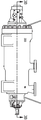
도 3a는 본 발명의 실시예들이 적용될 수 있는 로터리 펌프의 측면도이다.
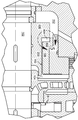
도 3b는 도 3a의 펌프의 단면도이다.
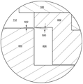
도 4는 본 발명의 일 실시예가 구현되는 도 3b의 펌프의 영역의 확대 단면도이다.
도 5는 저-스러스트(low-thrust) 구성에서 도시된 도 4의 실시예의 확대 단면도이다.
도 6은 고-스러스트(high-thrust) 구성에서 도시된 도 4의 실시예의 확대 단면도이다.
도 7은 그들 사이에 중간 챔버를 가진 2개의 압력 릴리프 갭들을 형성하는 계단식(step-wise) 회전자 구역과 고정자 영역을 포함하는 일 실시예의 단면도이다.
도 8은 본 발명의 일 실시예에서 축방향 샤프트 위치의 함수로서 스러스트를 보상하는 그래프로서, 계산 유체 역학에 의해 생성된 점들을 분석 곡선과 비교한다.1 is a schematic cross-sectional view of a prior art thrust compensation disc.
2 is a schematic cross-sectional view of a prior art thrust compensating drum.
3A is a side view of a rotary pump to which embodiments of the present invention can be applied.
3B is a cross-sectional view of the pump of FIG. 3A.
Figure 4 is an enlarged cross-sectional view of the region of the pump of Figure 3b in which an embodiment of the present invention is implemented.
5 is an enlarged cross-sectional view of the embodiment of FIG. 4 shown in a low-thrust configuration.
6 is an enlarged cross-sectional view of the embodiment of FIG. 4 shown in a high-thrust configuration.
7 is a cross-sectional view of one embodiment including a step-wise rotor zone and a stator region forming two pressure relief gaps with an intermediate chamber between them.
8 is a graph for compensating thrust as a function of axial shaft position in one embodiment of the present invention, comparing points generated by computational fluid dynamics with an analytical curve.
밸런싱 디스크와 유사한 자기-조절 스러스트 보상을 제공함으로써 축방향 스러스트의 완전하거나 거의 완전한 소거를 제공할 수 있는 한편, 밸런싱 메커니즘의 회전자 요소와 고정자 요소 사이의 접촉과 마모의 임의의 가능성을 사실상 없애는, 회전 샤프트 장치를 위한 축방향 스러스트 밸런싱 메커니즘이 개시된다. 개시된 디바이스는, 밸런싱 디스크(자체-조절 스러스트 보상)와 밸런싱 드럼(회전자 요소와 고정자 요소 사이의 축방향 접촉이 불가능)과 연관된 이점들을 단일 메커니즘으로 결합하기 때문에, 본 명세서에서 "하이브리드(hybrid)" 밸런싱 메커니즘으로 명명된다. 디바이스는 터보 펌프들, 컴프레서들, 터빈들 및 터보 차저들을 포함하지만 이에 한정되지 않는 축방향 스러스트를 받는 임의의 회전 샤프트 장치에 적용할 수 있다. By providing self-adjusting thrust compensation similar to a balancing disk, it can provide complete or near complete elimination of the axial thrust, while virtually eliminating any possibility of contact and wear between the rotor element and the stator element of the balancing mechanism, An axial thrust balancing mechanism for a rotating shaft device is disclosed. Since the disclosed device combines the advantages associated with the balancing disc (self-adjusting thrust compensation) and the balancing drum (no axial contact between the rotor element and the stator element) in a single mechanism, the term "hybrid" is used herein. It is called the balancing mechanism. The device is applicable to any rotating shaft apparatus subject to axial thrust, including but not limited to turbo pumps, compressors, turbines and turbochargers.
도 3a는 본 발명의 일 실시예가 포함되는 다단식 로터리 펌프의 측면도이다. 도 3b는 복수의 임펠러 스테이지들이 명확하게 보이는 도 3a의 펌프의 단면도이다. 도 4는 도 3b에 도시된 영역 내에서 최종 임펠러 스테이지 뒤의 영역의 확대도이다. 도 4에서, 개시된 실시예는 고정자 요소의 제1 영역(106) 내부에 들어 있는 회전자 요소의 제1 영역(200)에 의해 형성된 밸런싱 드럼 섹션을 포함하는 것을 알 수 있다. 또한, 실시예는, 제2 영역(402) 내부에 중간 챔버(404)가 형성되어 유체가 수집될 수 있도록, 직경이 더 작지만 고정자 요소의 대응 영역(402)의 바로 바깥에 위치하는 회전자 요소의 제2 영역(400)을 포함하는 하이브리드 밸런싱 섹션을 포함한다. 도 4의 점선 원으로 표시된 영역은 도 5에서 확대된다.Figure 3a is a side view of a multi-stage rotary pump including an embodiment of the present invention. 3B is a cross-sectional view of the pump of FIG. 3A with a plurality of impeller stages clearly visible. 4 is an enlarged view of the area behind the final impeller stage within the area shown in FIG. 3B. In FIG. 4, it can be seen that the disclosed embodiment includes a balancing drum section formed by the
도 5를 참조하면, 회전자 요소(400)와 고정자 요소(402)는, 회전자 요소(400)가 고정자 요소(402)와 동축이고 고정자 요소(402) 보다 더 작은 직경을 갖도록 구성된다. 직경들의 이러한 차이(502)는 회전자 요소(400)와 고정자 요소(402) 사이의 최소 갭(502)을 나타낸다. 그러나, 본 발명에 따르면, 도 2의 밸런싱 드럼(200)과 달리, 회전자 요소(400)는 고정자 요소(402)의 내부가 아닌 고정자 요소(402)에 인접하게 위치된다. 결과적으로, 정상 작동 동안 이러한 영역 내에서 회전자 요소와 고정자 요소 사이에 형성되는 압력 릴리프 갭(500)은, 수평도 아니고 수직도 아니지만, 대신에 인가되는 축방향 스러스트에 의해 샤프트(102)가 축방향으로 이동될 때 방향과 크기 모두 변한다.Referring to FIG. 5,
도 5에서, 스러스트가 상대적으로 낮기 때문에, 회전자 요소(400)가 고정자 요소(402)로부터 이격되게 함으로써, 중간 챔버(404)와 수집 챔버(112) 사이의 유효 압력 릴리프 갭(500)은 수평으로부터 대략 55°의 각도로 기울어진다. 도 6에서, 스러스트가 증가되면, 샤프트(102)를 오른쪽으로 이동시켜 갭(500)을 좁히고 갭의 방향을 수평에 더 가깝게 이동시킨다. 갭(500)이 더 좁아지면, 회전자 요소(400)를 가로지르는 압력 차이가 증가됨으로써, 증가된 스러스트를 보상하게 된다. 실시예들에서, 압력 릴리프 갭(500)의 각도는, 축방향 스러스트와 샤프트의 결과적인 변위에 따라, 0°와 70° 사이에서 변할 수 있다.In FIG. 5, because the thrust is relatively low, the effective
따라서, 개시된 보상 메커니즘에 따르면, 도 1과 같은 스러스트 보상 디스크에 의해 제공되는 피드백과 유사한 피드백 효과가 수립된다. 그러나, 개시된 메커니즘은, 회전자 요소(400)가 고정자 요소(402)보다 직경이 더 작기 때문에, 회전자 요소(400)와 고정자 요소(402) 사이의 직접적인 접촉의 임의의 위험이 없으므로, 그들 사이에 최소 갭(500)이 항상 유지된다. 만약, 회전 샤프트(102)가 큰 옵셋에 의해 변위되면, 회전자 요소(400)는 고정자 요소(402)의 내부로 간단히 들어가고,도 2의 보상 드럼(200)과 매우 유사하게 기능할 것이다.Accordingly, according to the disclosed compensation mechanism, a feedback effect similar to the feedback provided by the thrust compensation disk as shown in FIG. 1 is established. However, the disclosed mechanism does not have any risk of direct contact between the
전술한 바와 같이, 도 4 내지 도 6의 실시예는 밸런싱 드럼(106,200,110)과 본 발명의 하이브리드 밸런싱 메커니즘(402,400,404)을 결합한다. 따라서, 누설 챔버(104) 내에 수집되는 유체는 중간 챔버(404)에 도달하기 전에 드럼 갭(110)을 통해 흐를 필요가 있다. 그러면, 유체는 수집 챔버(112)에 도달하기 전에 각진 갭(500)을 통해 흐른다. 하이브리드 밸런싱 섹션의 최소 회전자/고정자 클리어런스(502)는 실시예의 요구 사항에 따라 동일한 크기 또는 상이한 크기일 수 있다.As described above, the embodiments of FIGS. 4-6 combine the balancing
일부 실시예들에서, 개시된 하이브리드 밸런싱 메커니즘은 제공된 유일한 스러스트 보상이며, 일부 실시예들에서, 개시된 메커니즘은 임펠러 또는 다른 샤프트-장착된 장치에 의해 발생되는 스러스트의 적어도 90%를 보상한다. In some embodiments, the disclosed hybrid balancing mechanism is the only thrust compensation provided, and in some embodiments, the disclosed mechanism compensates for at least 90% of thrust generated by an impeller or other shaft-mounted device.
도 7의 실시예에서, 누설 챔버(104)로부터 수집 챔버(112)로 유동하는 유체는 제2 가변 각도 갭(700)을 통과하여 수집 챔버(112) 속으로 유동하기 전에 제1 가변 각도 갭(500)을 통과하여 중간 챔버(604) 속으로 유동할 필요가 있다. 실시예들에서, 이러한 접근법은 샤프트(102)의 축방향 이동의 함수로서 누설 챔버 압력의 변화를 향상시킴으로써 개시된 메커니즘의 피드백 효과를 증가시킨다. 유사한 방식으로, 다양한 실시예들은 3개 이상의 가변 갭들과 중간 챔버들을 포함한다.In the embodiment of FIG. 7, the fluid flowing from the leaking
도 8은 시뮬레이션된 "CFD"(계산 유체 역학) 데이터의 점들과 회전 샤프트(102)의 축방향 위치의 함수로서 실시예에 의해 제공되는 보상 스러스트를 나타내는 분석 모델의 그래프이다. 이러한 특정의 적용에서, 축방향 위치가 곡선의 가장 가파른 영역에 있을 때, 축방향 위치가 0.1mm만 이동하면, 대략 2,000 파운드의 보상 스러스트의 변경으로 이어진다. 그러나, 이러한 수량은 특정 응용 분야에 따라 상당히 달라질 수 있다.8 is a graph of an analytical model showing the compensation thrust provided by the embodiment as a function of the points of the simulated “CFD” (calculated fluid dynamics) data and the axial position of the
본 발명의 실시예들에 대한 전술한 설명은 예시와 설명의 목적으로 제시되었다. 본 명세서의 각각의 페이지와 그에 대한 특성, 식별 또는 번호가 매겨진 모든 내용은 명세서의 형식이나 배치에 관계없이 모든 목적을 위해 본 명세서의 실질적인 부분으로 간주된다. The foregoing description of embodiments of the invention has been presented for purposes of illustration and description. Each page of this specification and all of its characteristics, identification or numbered contents is regarded as a substantial part of the specification for all purposes regardless of the format or arrangement of the specification.
본 명세서에서 예시적으로 개시된 본 발명은 본 명세서에 구체적으로 개시되지 않고 본질적으로 필요하지 않은 임의의 요소가 없는 상태에서 적절하게 실시될 수 있다. 그러나, 본 명세서는 완전한 것이 아니다. 본 발명은 제한된 수의 형태로 도시되어 있지만, 본 발명의 범위는 이들 형태로만 한정되는 것이 아니라 그 사상을 벗어나지 않으면서 다양한 변경과 수정이 가능하다. 당업자는 전술한 설명에 포함된 청구된 주제와 관련된 교시를 학습한 후에 본 개시에 비추어 많은 수정과 변형이 가능하다는 것을 이해할 것이다. 따라서, 청구된 주제는 본 명세서에서 달리 지시되거나 문맥상 명백하게 모순되지 않는 한, 전술한 요소의 모든 가능한 변형에서의 임의의 조합을 포함한다. 특히, 종속항이 서로 논리적으로 호환되지 않는 한, 이하의 종속항에 제시된 제한은 본 개시의 범위를 벗어나지 않으면서 임의의 수와 순서로 그들의 대응하는 독립항과 조합될 수 있다.The present invention exemplarily disclosed herein may be suitably practiced without any elements not specifically disclosed herein and essentially unnecessary. However, this specification is not complete. Although the present invention is shown in a limited number of forms, the scope of the present invention is not limited only to these forms, and various changes and modifications can be made without departing from the spirit. Those skilled in the art will appreciate that many modifications and variations are possible in light of the present disclosure after learning the teachings related to the claimed subject matter included in the foregoing description. Accordingly, the claimed subject matter includes any combination in all possible variations of the foregoing elements, unless otherwise indicated herein or otherwise clearly contradicted by context. In particular, unless the dependent claims are logically compatible with each other, the limitations set forth in the dependent claims below may be combined with their corresponding independent claims in any number and order without departing from the scope of the present disclosure.
102...회전 샤프트
104...누설 챔버
110...드럼 갭
112...수집 챔버
200...밸런싱 드럼
400...회전자 요소
402...고정자 요소
404...중간 챔버
500...갭
502...최소 회전자/고정자 클리어런스
604...중간 챔버102 ... rotating shaft
104 ... Leak chamber
110 ... drum gap
112 ... Collection chamber
200 ... balancing drum
400 ... rotor element
402 ... stator element
404 ... intermediate chamber
500 ... gap
502 ... Minimum rotor / stator clearance
604 ... intermediate chamber
Claims (11)
회전가능한 샤프트에 길이 방향으로 고정되고 상기 샤프트와 동축인 제1 세그먼트, 및 상기 샤프트를 둘러싸지만 길이 방향으로 상기 샤프트에 고정되지 않는 제2 세그먼트를 구비하고, 상기 제1 세그먼트와 상기 제2 세그먼트는 상기 장치의 작동 동안 그들 사이에 상대 회전이 있도록 구성되고, 상기 제2 세그먼트는 고압 유체 영역과 유체 연통하고;
상기 제1 세그먼트와 상기 제2 세그먼트 중 어느 하나에 포함된 원통형 수형(male) 섹션, 및 상기 제1 세그먼트와 상기 제2 세그먼트 중 다른 하나에 포함된 원통형 암형(female) 섹션을 구비하고, 상기 수형 섹션은 원형 리딩 에지에 의해 종결되고 상기 암형 섹션은 상기 수형 섹션의 상기 원형 리딩 에지보다 직경이 더 큰 원형 개구에 의해 전방 에지에서 종결되고;
상기 수형 섹션의 리딩 에지와 상기 암형 섹션의 전방 에지 사이에 압력 릴리프 갭을 형성할 수 있도록, 상기 수형 섹션의 상기 리딩 에지는 상기 암형 섹션 속으로 들어가지 않고 상기 암형 섹션의 상기 전방 에지에 근접하게 위치되고, 가압된 유체는 상기 압력 릴리프 갭을 통해 상기 제2 세그먼트로부터 상기 제1 세그먼트를 지나서 저압 영역으로 유동할 수 있는 한편, 상기 축방향 스러스트에 대항하는 축방향 보상력은 상기 가압된 유체에 의해 상기 제1 세그먼트에 인가되고,
상기 압력 릴리프 갭은 상기 축방향 변위에 의해 크기가 감소됨으로써, 축방향 스러스트와 축방향 변위가 증가될 때 보상력이 증가되고, 결과적으로 상기 압력 릴리프 갭의 크기가 감소되는, 스러스트 조절 메커니즘.
A thrust adjustment mechanism of a device having a shaft subjected to an axial displacement generated by an axial thrust,
A first segment fixed in the longitudinal direction to the rotatable shaft and coaxial with the shaft, and a second segment surrounding the shaft but not fixed to the shaft in the longitudinal direction, wherein the first segment and the second segment are Configured to have a relative rotation between them during operation of the device, the second segment in fluid communication with the high pressure fluid region;
And a cylindrical male section included in one of the first segment and the second segment, and a cylindrical female section included in the other of the first segment and the second segment, The section is terminated by a circular leading edge and the female section is terminated at the front edge by a circular opening with a diameter larger than the circular leading edge of the male section;
In order to form a pressure relief gap between the leading edge of the male section and the front edge of the female section, the leading edge of the male section does not enter the female section and is close to the front edge of the female section. The positioned, pressurized fluid can flow through the pressure relief gap from the second segment past the first segment to a low pressure region, while an axial compensating force against the axial thrust is applied to the pressurized fluid. By being applied to the first segment,
The pressure relief gap is reduced in size by the axial displacement, thereby increasing the compensation force when the axial thrust and the axial displacement are increased, and consequently the size of the pressure relief gap is reduced.
상기 장치는 컴프레서(compressor)인, 스러스트 조절 메커니즘.
In claim 1,
The device is a compressor, a thrust adjustment mechanism.
상기 장치는 터빈(turbin)인, 스러스트 조절 메커니즘.
In claim 1 or claim 2,
The device is a turbine, a thrust regulating mechanism.
상기 장치는 터빈으로서 회전하는 펌프인, 스러스트 조절 메커니즘.
In any one of claims 1 to 3,
The device is a turbine rotating pump, thrust regulating mechanism.
상기 장치는 터보 펌프인, 스러스트 조절 메커니즘.
In any one of claims 1 to 4,
The device is a turbo pump, thrust adjustment mechanism.
상기 장치는 다단 터보 펌프인, 스러스트 조절 메커니즘.
In claim 5,
The device is a multi-stage turbo pump, thrust adjustment mechanism.
상기 암형 섹션은 상기 터보 펌프의 임펠러를 지나서 누출되는 유체로 채워지도록 구성된, 스러스트 조절 메커니즘.
In claim 5 or claim 6,
The thrust adjustment mechanism is configured such that the female section is filled with fluid leaking past the impeller of the turbopump.
상기 저압 영역은 상기 장치의 유체 입구 영역인, 스러스트 조절 메커니즘.
In any one of claims 1 to 7,
The low pressure region is the fluid inlet region of the device, thrust adjustment mechanism.
상기 장치는 상기 축방향 스러스트를 대향하지만 상기 축방향 스러스트를 소거하지 않도록 구성되는 스러스트 감소 드럼 메커니즘을 더 구비하고,
상기 드럼 메커니즘은 비-회전 통로 내에서 상기 통로에 대하여 회전하도록 구성된 원통형 드럼 섹션, 및 상기 축방향 변위와 무관한 방사상 갭 크기를 가지고 상기 드럼과 상기 통로 사이에 형성된 방사상 갭을 구비하고,
상기 드럼과 상기 통로의 어느 하나는 길이 방향으로 상기 샤프트에 고정되고, 상기 드럼 메커니즘에 의해 보상되지 않는 잔류 축방향 스러스트는 상기 스러스트 조절 메커니즘에 의해 조절되는, 스러스트 조절 메커니즘.
In any one of claims 1 to 8,
The apparatus further comprises a thrust reducing drum mechanism which is opposite the axial thrust but is configured not to cancel the axial thrust,
The drum mechanism has a cylindrical drum section configured to rotate relative to the passage in a non-rotating passage, and a radial gap formed between the drum and the passage with a radial gap size independent of the axial displacement,
The thrust adjusting mechanism wherein any one of the drum and the passage is fixed to the shaft in the longitudinal direction, and the residual axial thrust not compensated by the drum mechanism is adjusted by the thrust adjusting mechanism.
상기 장치는 복수의 수형 섹션들과 대응하는 복수의 암형 섹션들을 포함하고,
대응하는 수형 섹션들과 암형 섹션들의 리딩 에지와 전방 에지는, 가압된 유체가 고압 유체 영역으로부터 저압 영역으로 유동함에 따라 상기 가압된 유체가 가로지르는 복수의 갭들과 중간 챔버들을 형성하기 위해, 서로 인접하게 되어 있고,
복수의 갭들의 각각은 회전가능한 샤프트의 축방향 변위에 의해 감소되는 크기를 가진, 스러스트 조절 메커니즘.
In any one of claims 1 to 9,
The device comprises a plurality of female sections and a plurality of female sections corresponding to the
The leading and leading edges of the corresponding male and female sections are adjacent to each other to form a plurality of gaps and intermediate chambers across which the pressurized fluid traverses as the pressurized fluid flows from the high pressure fluid region to the low pressure region. To do,
Each of the plurality of gaps has a size reduced by the axial displacement of the rotatable shaft, thrust adjustment mechanism.
회전자 요소의 수형 섹션이 고정자 요소의 암형 섹션으로 들어가기 전에 보상력의 크기가 축방향 스러스트의 크기의 적어도 90%까지 상승하도록 구성된, 메커니즘.
In any one of claims 1 to 10,
The mechanism configured to increase the magnitude of the compensating force to at least 90% of the size of the axial thrust before the male section of the rotor element enters the female section of the stator element.
Applications Claiming Priority (3)
| Application Number | Priority Date | Filing Date | Title |
|---|---|---|---|
| US15/691,899 | 2017-08-31 | ||
| US15/691,899 US10513928B2 (en) | 2017-08-31 | 2017-08-31 | Axial thrust balancing device |
| PCT/US2018/042464 WO2019045894A1 (en) | 2017-08-31 | 2018-07-17 | Axial thrust balancing device |
Publications (2)
| Publication Number | Publication Date |
|---|---|
| KR20200037814A true KR20200037814A (en) | 2020-04-09 |
| KR102370184B1 KR102370184B1 (en) | 2022-03-03 |
Family
ID=65436925
Family Applications (1)
| Application Number | Title | Priority Date | Filing Date |
|---|---|---|---|
| KR1020207005539A Active KR102370184B1 (en) | 2017-08-31 | 2018-07-17 | Axial Thrust Balancing Device |
Country Status (10)
| Country | Link |
|---|---|
| US (1) | US10513928B2 (en) |
| EP (1) | EP3676499B1 (en) |
| JP (1) | JP6953624B2 (en) |
| KR (1) | KR102370184B1 (en) |
| CN (1) | CN111033053B (en) |
| AR (1) | AR112990A1 (en) |
| BR (1) | BR112020002805B1 (en) |
| MX (1) | MX2020002236A (en) |
| SA (1) | SA520411411B1 (en) |
| WO (1) | WO2019045894A1 (en) |
Cited By (1)
| Publication number | Priority date | Publication date | Assignee | Title |
|---|---|---|---|---|
| KR102876382B1 (en) * | 2024-11-22 | 2025-10-27 | 현대중공업터보기계 주식회사 | Centrifugal Pump With Balancing Structure To Reduce Axial Thrust |
Families Citing this family (7)
| Publication number | Priority date | Publication date | Assignee | Title |
|---|---|---|---|---|
| CN110119564B (en) * | 2019-05-07 | 2022-02-15 | 中铁工程装备集团有限公司 | Segment preselection method based on automatic measurement of shield tail clearance |
| CN111255528B (en) * | 2020-01-22 | 2022-03-04 | 天津大学 | A balancing device for the axial force of a kilowatt-scale supercritical carbon dioxide turbine |
| CN111173770A (en) * | 2020-03-12 | 2020-05-19 | 中国大唐集团科学技术研究院有限公司华东电力试验研究院 | Axial force balance structure of centrifugal pump |
| CN111946638B (en) * | 2020-09-17 | 2024-11-05 | 珠海格力电器股份有限公司 | Multistage centrifugal compressor and refrigeration system |
| JP2022068479A (en) * | 2020-10-22 | 2022-05-10 | 三菱重工コンプレッサ株式会社 | Rotary machine and geared compressor |
| KR102825917B1 (en) | 2023-09-01 | 2025-06-27 | 한국항공우주연구원 | Turbopump capable of balancing of axial thrust |
| CN119982621B (en) * | 2025-02-26 | 2025-10-28 | 清华大学 | Axial force adjusting structure of closed impeller centrifugal compressor and centrifugal compressor |
Citations (4)
| Publication number | Priority date | Publication date | Assignee | Title |
|---|---|---|---|---|
| JP2006077694A (en) * | 2004-09-10 | 2006-03-23 | Mitsubishi Heavy Ind Ltd | Centrifugal pump |
| JP2007085223A (en) * | 2005-09-21 | 2007-04-05 | Mitsubishi Heavy Ind Ltd | Balance mechanism for axial thrust |
| JP2011202641A (en) * | 2010-03-26 | 2011-10-13 | Honda Motor Co Ltd | Electric compressor |
| JP2014134131A (en) * | 2013-01-10 | 2014-07-24 | Panasonic Corp | Turbo compressor |
Family Cites Families (23)
| Publication number | Priority date | Publication date | Assignee | Title |
|---|---|---|---|---|
| CH501839A (en) * | 1966-11-12 | 1971-01-15 | Zabrzanska Fabryka Masz Gornic | Dynamic pump |
| US3614181A (en) * | 1970-07-02 | 1971-10-19 | Us Air Force | Magnetic bearing for combined radial and thrust loads |
| US5209652A (en) * | 1991-12-06 | 1993-05-11 | Allied-Signal, Inc. | Compact cryogenic turbopump |
| ES2138060T3 (en) * | 1994-07-25 | 2000-01-01 | Sulzer Pumpen Ag | CENTRIFUGAL PUMP WITH A LIFTING DEVICE. |
| CN2241242Y (en) * | 1995-03-04 | 1996-11-27 | 辛育霖 | Propeller pump |
| AU9068798A (en) * | 1997-07-26 | 1999-02-16 | Allweiler Ag | Mounting for a turbo-machine rotor and its use |
| JP2007005223A (en) | 2005-06-27 | 2007-01-11 | Shin Etsu Polymer Co Ltd | Cover member for push-button switch |
| US7731476B2 (en) | 2007-01-30 | 2010-06-08 | Technology Commercialization Corp. | Method and device for reducing axial thrust and radial oscillations and rotary machines using same |
| FR2941019A1 (en) * | 2009-01-09 | 2010-07-16 | Snecma | PUMP WITH AXIAL BALANCING DEVICE |
| FR2945330B1 (en) * | 2009-05-11 | 2011-07-15 | Snecma | CENTRIFUGAL PUMP WITH DOUBLE EXHAUST. |
| CN201636067U (en) * | 2010-04-26 | 2010-11-17 | 佳木斯大学 | Axial force balance device of ultra-deep well submersible pump |
| DE102011085681A1 (en) * | 2011-11-03 | 2013-05-08 | Abb Turbo Systems Ag | Hydrodynamic thrust bearing |
| CN202579208U (en) * | 2012-05-17 | 2012-12-05 | 烟台盛泉泵业有限公司 | Improved magnetic pump |
| CN104747458A (en) * | 2013-12-27 | 2015-07-01 | 博西华电器(江苏)有限公司 | Liquid draining pump and household appliance with pump |
| JP2016061252A (en) * | 2014-09-19 | 2016-04-25 | 三菱重工業株式会社 | Rotary electric machine |
| CN204226256U (en) * | 2014-10-08 | 2015-03-25 | 中国船舶重工集团公司第七0四研究所 | Double gap high drag balance device |
| KR102213232B1 (en) * | 2014-10-20 | 2021-02-08 | 현대중공업터보기계 주식회사 | High Pressure Horizontal Type Pump |
| DE102014226951A1 (en) * | 2014-12-23 | 2016-06-23 | Robert Bosch Gmbh | turbomachinery |
| JP2016148308A (en) * | 2015-02-13 | 2016-08-18 | 三菱重工業株式会社 | Centrifugal compressor and geared centrifugal compressor |
| CN204755416U (en) * | 2015-07-29 | 2015-11-11 | 湖北三宁化工股份有限公司 | Air stripping liquid turbopump |
| US20170130730A1 (en) * | 2015-11-10 | 2017-05-11 | Onesubsea Ip Uk Limited | Axial bearing offloading in fluid processing machines |
| CN206129676U (en) * | 2016-08-31 | 2017-04-26 | 天津甘泉集团有限公司 | Submerged motor pump axial force balancing unit |
| EP3412915B1 (en) * | 2017-06-09 | 2019-12-25 | Xylem Europe GmbH | Self-adjusting drum system |
-
2017
- 2017-08-31 US US15/691,899 patent/US10513928B2/en active Active
-
2018
- 2018-07-17 MX MX2020002236A patent/MX2020002236A/en unknown
- 2018-07-17 WO PCT/US2018/042464 patent/WO2019045894A1/en not_active Ceased
- 2018-07-17 BR BR112020002805-3A patent/BR112020002805B1/en active IP Right Grant
- 2018-07-17 JP JP2020511531A patent/JP6953624B2/en active Active
- 2018-07-17 CN CN201880052925.7A patent/CN111033053B/en active Active
- 2018-07-17 KR KR1020207005539A patent/KR102370184B1/en active Active
- 2018-07-17 EP EP18852610.7A patent/EP3676499B1/en active Active
- 2018-08-30 AR ARP180102467A patent/AR112990A1/en active IP Right Grant
-
2020
- 2020-02-25 SA SA520411411A patent/SA520411411B1/en unknown
Patent Citations (4)
| Publication number | Priority date | Publication date | Assignee | Title |
|---|---|---|---|---|
| JP2006077694A (en) * | 2004-09-10 | 2006-03-23 | Mitsubishi Heavy Ind Ltd | Centrifugal pump |
| JP2007085223A (en) * | 2005-09-21 | 2007-04-05 | Mitsubishi Heavy Ind Ltd | Balance mechanism for axial thrust |
| JP2011202641A (en) * | 2010-03-26 | 2011-10-13 | Honda Motor Co Ltd | Electric compressor |
| JP2014134131A (en) * | 2013-01-10 | 2014-07-24 | Panasonic Corp | Turbo compressor |
Cited By (1)
| Publication number | Priority date | Publication date | Assignee | Title |
|---|---|---|---|---|
| KR102876382B1 (en) * | 2024-11-22 | 2025-10-27 | 현대중공업터보기계 주식회사 | Centrifugal Pump With Balancing Structure To Reduce Axial Thrust |
Also Published As
| Publication number | Publication date |
|---|---|
| MX2020002236A (en) | 2020-07-20 |
| BR112020002805B1 (en) | 2023-04-18 |
| AR112990A1 (en) | 2020-01-15 |
| WO2019045894A1 (en) | 2019-03-07 |
| EP3676499A1 (en) | 2020-07-08 |
| CN111033053B (en) | 2021-06-15 |
| EP3676499B1 (en) | 2022-01-26 |
| BR112020002805A2 (en) | 2020-07-28 |
| KR102370184B1 (en) | 2022-03-03 |
| US20190063221A1 (en) | 2019-02-28 |
| SA520411411B1 (en) | 2022-09-13 |
| EP3676499A4 (en) | 2020-08-12 |
| CN111033053A (en) | 2020-04-17 |
| US10513928B2 (en) | 2019-12-24 |
| JP2020532673A (en) | 2020-11-12 |
| JP6953624B2 (en) | 2021-10-27 |
Similar Documents
| Publication | Publication Date | Title |
|---|---|---|
| KR102370184B1 (en) | Axial Thrust Balancing Device | |
| US7775763B1 (en) | Centrifugal pump with rotor thrust balancing seal | |
| RU2687474C2 (en) | Gas turbine engine compressor comprising blades with variable installation angle | |
| CN105899763B (en) | Turbine Bearing Housing | |
| JP7074442B2 (en) | Compressor | |
| JP6792086B2 (en) | Turbo compressor and how to operate the turbo compressor | |
| US10094388B2 (en) | Load-relieving device | |
| EP0521007A1 (en) | Control system for regulating the axial loading of a rotor of a fluid machine | |
| US20210324862A1 (en) | Centrifugal pump for conveying a fluid | |
| US11572881B2 (en) | Compressor system | |
| US20160327050A1 (en) | Diaphragm and centrifugal rotating machine | |
| US20120051885A1 (en) | Double exhaust centrifugal pump | |
| US20190120056A1 (en) | Radial turbomachine with axial thrust compensation | |
| US20200355219A1 (en) | Tilting pad journal bearing and rotary machine using same | |
| GB2442320A (en) | Pump with axial balancing | |
| KR102240987B1 (en) | Bearing device and rotating machine | |
| US10871164B2 (en) | Centrifugal compressor | |
| US11788533B2 (en) | Multistage centrifugal pump | |
| US11971046B2 (en) | Rotary pump for conveying a fluid | |
| US20220042513A1 (en) | A Multistage Pump With Axial Thrust Optimization | |
| KR100917250B1 (en) | Turbomachinery with bellows for automatic axial thrust | |
| WO1992019869A1 (en) | Co-planar seal arrangement | |
| EP3936726A1 (en) | Adjusting discharge flow of a multistage pump by setting balance drum clearance | |
| WO2021149244A1 (en) | Turbocharger |
Legal Events
| Date | Code | Title | Description |
|---|---|---|---|
| PA0105 | International application |
St.27 status event code: A-0-1-A10-A15-nap-PA0105 |
|
| PG1501 | Laying open of application |
St.27 status event code: A-1-1-Q10-Q12-nap-PG1501 |
|
| A201 | Request for examination | ||
| PA0201 | Request for examination |
St.27 status event code: A-1-2-D10-D11-exm-PA0201 |
|
| E902 | Notification of reason for refusal | ||
| PE0902 | Notice of grounds for rejection |
St.27 status event code: A-1-2-D10-D21-exm-PE0902 |
|
| P11-X000 | Amendment of application requested |
St.27 status event code: A-2-2-P10-P11-nap-X000 |
|
| P13-X000 | Application amended |
St.27 status event code: A-2-2-P10-P13-nap-X000 |
|
| E701 | Decision to grant or registration of patent right | ||
| PE0701 | Decision of registration |
St.27 status event code: A-1-2-D10-D22-exm-PE0701 |
|
| GRNT | Written decision to grant | ||
| PR0701 | Registration of establishment |
St.27 status event code: A-2-4-F10-F11-exm-PR0701 |
|
| PR1002 | Payment of registration fee |
St.27 status event code: A-2-2-U10-U12-oth-PR1002 Fee payment year number: 1 |
|
| PG1601 | Publication of registration |
St.27 status event code: A-4-4-Q10-Q13-nap-PG1601 |
|
| PN2301 | Change of applicant |
St.27 status event code: A-5-5-R10-R11-asn-PN2301 |
|
| PN2301 | Change of applicant |
St.27 status event code: A-5-5-R10-R14-asn-PN2301 |
|
| R18-X000 | Changes to party contact information recorded |
St.27 status event code: A-5-5-R10-R18-oth-X000 |
|
| PR1001 | Payment of annual fee |
St.27 status event code: A-4-4-U10-U11-oth-PR1001 Fee payment year number: 4 |
|
| U11 | Full renewal or maintenance fee paid |
Free format text: ST27 STATUS EVENT CODE: A-4-4-U10-U11-OTH-PR1001 (AS PROVIDED BY THE NATIONAL OFFICE) Year of fee payment: 4 |