KR20200040865A - LCD alignment optical device - Google Patents
LCD alignment optical device Download PDFInfo
- Publication number
- KR20200040865A KR20200040865A KR1020207008545A KR20207008545A KR20200040865A KR 20200040865 A KR20200040865 A KR 20200040865A KR 1020207008545 A KR1020207008545 A KR 1020207008545A KR 20207008545 A KR20207008545 A KR 20207008545A KR 20200040865 A KR20200040865 A KR 20200040865A
- Authority
- KR
- South Korea
- Prior art keywords
- liquid crystal
- alignment
- alignment layer
- pretilt
- optical device
- Prior art date
- Legal status (The legal status is an assumption and is not a legal conclusion. Google has not performed a legal analysis and makes no representation as to the accuracy of the status listed.)
- Granted
Links
Images


Classifications
-
- G—PHYSICS
- G02—OPTICS
- G02F—OPTICAL DEVICES OR ARRANGEMENTS FOR THE CONTROL OF LIGHT BY MODIFICATION OF THE OPTICAL PROPERTIES OF THE MEDIA OF THE ELEMENTS INVOLVED THEREIN; NON-LINEAR OPTICS; FREQUENCY-CHANGING OF LIGHT; OPTICAL LOGIC ELEMENTS; OPTICAL ANALOGUE/DIGITAL CONVERTERS
- G02F1/00—Devices or arrangements for the control of the intensity, colour, phase, polarisation or direction of light arriving from an independent light source, e.g. switching, gating or modulating; Non-linear optics
- G02F1/01—Devices or arrangements for the control of the intensity, colour, phase, polarisation or direction of light arriving from an independent light source, e.g. switching, gating or modulating; Non-linear optics for the control of the intensity, phase, polarisation or colour
- G02F1/13—Devices or arrangements for the control of the intensity, colour, phase, polarisation or direction of light arriving from an independent light source, e.g. switching, gating or modulating; Non-linear optics for the control of the intensity, phase, polarisation or colour based on liquid crystals, e.g. single liquid crystal display cells
- G02F1/133—Constructional arrangements; Operation of liquid crystal cells; Circuit arrangements
- G02F1/1333—Constructional arrangements; Manufacturing methods
- G02F1/133371—Cells with varying thickness of the liquid crystal layer
-
- G—PHYSICS
- G02—OPTICS
- G02C—SPECTACLES; SUNGLASSES OR GOGGLES INSOFAR AS THEY HAVE THE SAME FEATURES AS SPECTACLES; CONTACT LENSES
- G02C7/00—Optical parts
- G02C7/02—Lenses; Lens systems ; Methods of designing lenses
- G02C7/08—Auxiliary lenses; Arrangements for varying focal length
- G02C7/081—Ophthalmic lenses with variable focal length
- G02C7/083—Electrooptic lenses
-
- G—PHYSICS
- G02—OPTICS
- G02F—OPTICAL DEVICES OR ARRANGEMENTS FOR THE CONTROL OF LIGHT BY MODIFICATION OF THE OPTICAL PROPERTIES OF THE MEDIA OF THE ELEMENTS INVOLVED THEREIN; NON-LINEAR OPTICS; FREQUENCY-CHANGING OF LIGHT; OPTICAL LOGIC ELEMENTS; OPTICAL ANALOGUE/DIGITAL CONVERTERS
- G02F1/00—Devices or arrangements for the control of the intensity, colour, phase, polarisation or direction of light arriving from an independent light source, e.g. switching, gating or modulating; Non-linear optics
- G02F1/01—Devices or arrangements for the control of the intensity, colour, phase, polarisation or direction of light arriving from an independent light source, e.g. switching, gating or modulating; Non-linear optics for the control of the intensity, phase, polarisation or colour
- G02F1/13—Devices or arrangements for the control of the intensity, colour, phase, polarisation or direction of light arriving from an independent light source, e.g. switching, gating or modulating; Non-linear optics for the control of the intensity, phase, polarisation or colour based on liquid crystals, e.g. single liquid crystal display cells
- G02F1/133—Constructional arrangements; Operation of liquid crystal cells; Circuit arrangements
- G02F1/1333—Constructional arrangements; Manufacturing methods
- G02F1/1337—Surface-induced orientation of the liquid crystal molecules, e.g. by alignment layers
-
- G—PHYSICS
- G02—OPTICS
- G02F—OPTICAL DEVICES OR ARRANGEMENTS FOR THE CONTROL OF LIGHT BY MODIFICATION OF THE OPTICAL PROPERTIES OF THE MEDIA OF THE ELEMENTS INVOLVED THEREIN; NON-LINEAR OPTICS; FREQUENCY-CHANGING OF LIGHT; OPTICAL LOGIC ELEMENTS; OPTICAL ANALOGUE/DIGITAL CONVERTERS
- G02F1/00—Devices or arrangements for the control of the intensity, colour, phase, polarisation or direction of light arriving from an independent light source, e.g. switching, gating or modulating; Non-linear optics
- G02F1/01—Devices or arrangements for the control of the intensity, colour, phase, polarisation or direction of light arriving from an independent light source, e.g. switching, gating or modulating; Non-linear optics for the control of the intensity, phase, polarisation or colour
- G02F1/13—Devices or arrangements for the control of the intensity, colour, phase, polarisation or direction of light arriving from an independent light source, e.g. switching, gating or modulating; Non-linear optics for the control of the intensity, phase, polarisation or colour based on liquid crystals, e.g. single liquid crystal display cells
- G02F1/133—Constructional arrangements; Operation of liquid crystal cells; Circuit arrangements
- G02F1/1333—Constructional arrangements; Manufacturing methods
- G02F1/1337—Surface-induced orientation of the liquid crystal molecules, e.g. by alignment layers
- G02F1/133742—Surface-induced orientation of the liquid crystal molecules, e.g. by alignment layers for homeotropic alignment
-
- G—PHYSICS
- G02—OPTICS
- G02F—OPTICAL DEVICES OR ARRANGEMENTS FOR THE CONTROL OF LIGHT BY MODIFICATION OF THE OPTICAL PROPERTIES OF THE MEDIA OF THE ELEMENTS INVOLVED THEREIN; NON-LINEAR OPTICS; FREQUENCY-CHANGING OF LIGHT; OPTICAL LOGIC ELEMENTS; OPTICAL ANALOGUE/DIGITAL CONVERTERS
- G02F1/00—Devices or arrangements for the control of the intensity, colour, phase, polarisation or direction of light arriving from an independent light source, e.g. switching, gating or modulating; Non-linear optics
- G02F1/01—Devices or arrangements for the control of the intensity, colour, phase, polarisation or direction of light arriving from an independent light source, e.g. switching, gating or modulating; Non-linear optics for the control of the intensity, phase, polarisation or colour
- G02F1/13—Devices or arrangements for the control of the intensity, colour, phase, polarisation or direction of light arriving from an independent light source, e.g. switching, gating or modulating; Non-linear optics for the control of the intensity, phase, polarisation or colour based on liquid crystals, e.g. single liquid crystal display cells
- G02F1/133—Constructional arrangements; Operation of liquid crystal cells; Circuit arrangements
- G02F1/1333—Constructional arrangements; Manufacturing methods
- G02F1/1337—Surface-induced orientation of the liquid crystal molecules, e.g. by alignment layers
- G02F1/133746—Surface-induced orientation of the liquid crystal molecules, e.g. by alignment layers for high pretilt angles, i.e. higher than 15 degrees
-
- G—PHYSICS
- G02—OPTICS
- G02F—OPTICAL DEVICES OR ARRANGEMENTS FOR THE CONTROL OF LIGHT BY MODIFICATION OF THE OPTICAL PROPERTIES OF THE MEDIA OF THE ELEMENTS INVOLVED THEREIN; NON-LINEAR OPTICS; FREQUENCY-CHANGING OF LIGHT; OPTICAL LOGIC ELEMENTS; OPTICAL ANALOGUE/DIGITAL CONVERTERS
- G02F1/00—Devices or arrangements for the control of the intensity, colour, phase, polarisation or direction of light arriving from an independent light source, e.g. switching, gating or modulating; Non-linear optics
- G02F1/01—Devices or arrangements for the control of the intensity, colour, phase, polarisation or direction of light arriving from an independent light source, e.g. switching, gating or modulating; Non-linear optics for the control of the intensity, phase, polarisation or colour
- G02F1/13—Devices or arrangements for the control of the intensity, colour, phase, polarisation or direction of light arriving from an independent light source, e.g. switching, gating or modulating; Non-linear optics for the control of the intensity, phase, polarisation or colour based on liquid crystals, e.g. single liquid crystal display cells
- G02F1/133—Constructional arrangements; Operation of liquid crystal cells; Circuit arrangements
- G02F1/1333—Constructional arrangements; Manufacturing methods
- G02F1/1337—Surface-induced orientation of the liquid crystal molecules, e.g. by alignment layers
- G02F1/133753—Surface-induced orientation of the liquid crystal molecules, e.g. by alignment layers with different alignment orientations or pretilt angles on a same surface, e.g. for grey scale or improved viewing angle
- G02F1/133757—Surface-induced orientation of the liquid crystal molecules, e.g. by alignment layers with different alignment orientations or pretilt angles on a same surface, e.g. for grey scale or improved viewing angle with different alignment orientations
-
- G—PHYSICS
- G02—OPTICS
- G02F—OPTICAL DEVICES OR ARRANGEMENTS FOR THE CONTROL OF LIGHT BY MODIFICATION OF THE OPTICAL PROPERTIES OF THE MEDIA OF THE ELEMENTS INVOLVED THEREIN; NON-LINEAR OPTICS; FREQUENCY-CHANGING OF LIGHT; OPTICAL LOGIC ELEMENTS; OPTICAL ANALOGUE/DIGITAL CONVERTERS
- G02F1/00—Devices or arrangements for the control of the intensity, colour, phase, polarisation or direction of light arriving from an independent light source, e.g. switching, gating or modulating; Non-linear optics
- G02F1/01—Devices or arrangements for the control of the intensity, colour, phase, polarisation or direction of light arriving from an independent light source, e.g. switching, gating or modulating; Non-linear optics for the control of the intensity, phase, polarisation or colour
- G02F1/13—Devices or arrangements for the control of the intensity, colour, phase, polarisation or direction of light arriving from an independent light source, e.g. switching, gating or modulating; Non-linear optics for the control of the intensity, phase, polarisation or colour based on liquid crystals, e.g. single liquid crystal display cells
- G02F1/133—Constructional arrangements; Operation of liquid crystal cells; Circuit arrangements
- G02F1/1333—Constructional arrangements; Manufacturing methods
- G02F1/1337—Surface-induced orientation of the liquid crystal molecules, e.g. by alignment layers
- G02F1/133753—Surface-induced orientation of the liquid crystal molecules, e.g. by alignment layers with different alignment orientations or pretilt angles on a same surface, e.g. for grey scale or improved viewing angle
- G02F1/133761—Surface-induced orientation of the liquid crystal molecules, e.g. by alignment layers with different alignment orientations or pretilt angles on a same surface, e.g. for grey scale or improved viewing angle with different pretilt angles
-
- G—PHYSICS
- G02—OPTICS
- G02F—OPTICAL DEVICES OR ARRANGEMENTS FOR THE CONTROL OF LIGHT BY MODIFICATION OF THE OPTICAL PROPERTIES OF THE MEDIA OF THE ELEMENTS INVOLVED THEREIN; NON-LINEAR OPTICS; FREQUENCY-CHANGING OF LIGHT; OPTICAL LOGIC ELEMENTS; OPTICAL ANALOGUE/DIGITAL CONVERTERS
- G02F1/00—Devices or arrangements for the control of the intensity, colour, phase, polarisation or direction of light arriving from an independent light source, e.g. switching, gating or modulating; Non-linear optics
- G02F1/01—Devices or arrangements for the control of the intensity, colour, phase, polarisation or direction of light arriving from an independent light source, e.g. switching, gating or modulating; Non-linear optics for the control of the intensity, phase, polarisation or colour
- G02F1/13—Devices or arrangements for the control of the intensity, colour, phase, polarisation or direction of light arriving from an independent light source, e.g. switching, gating or modulating; Non-linear optics for the control of the intensity, phase, polarisation or colour based on liquid crystals, e.g. single liquid crystal display cells
- G02F1/133—Constructional arrangements; Operation of liquid crystal cells; Circuit arrangements
- G02F1/1333—Constructional arrangements; Manufacturing methods
- G02F1/1337—Surface-induced orientation of the liquid crystal molecules, e.g. by alignment layers
- G02F1/133776—Surface-induced orientation of the liquid crystal molecules, e.g. by alignment layers having structures locally influencing the alignment, e.g. unevenness
-
- G—PHYSICS
- G02—OPTICS
- G02F—OPTICAL DEVICES OR ARRANGEMENTS FOR THE CONTROL OF LIGHT BY MODIFICATION OF THE OPTICAL PROPERTIES OF THE MEDIA OF THE ELEMENTS INVOLVED THEREIN; NON-LINEAR OPTICS; FREQUENCY-CHANGING OF LIGHT; OPTICAL LOGIC ELEMENTS; OPTICAL ANALOGUE/DIGITAL CONVERTERS
- G02F1/00—Devices or arrangements for the control of the intensity, colour, phase, polarisation or direction of light arriving from an independent light source, e.g. switching, gating or modulating; Non-linear optics
- G02F1/29—Devices or arrangements for the control of the intensity, colour, phase, polarisation or direction of light arriving from an independent light source, e.g. switching, gating or modulating; Non-linear optics for the control of the position or the direction of light beams, i.e. deflection
-
- G—PHYSICS
- G02—OPTICS
- G02F—OPTICAL DEVICES OR ARRANGEMENTS FOR THE CONTROL OF LIGHT BY MODIFICATION OF THE OPTICAL PROPERTIES OF THE MEDIA OF THE ELEMENTS INVOLVED THEREIN; NON-LINEAR OPTICS; FREQUENCY-CHANGING OF LIGHT; OPTICAL LOGIC ELEMENTS; OPTICAL ANALOGUE/DIGITAL CONVERTERS
- G02F1/00—Devices or arrangements for the control of the intensity, colour, phase, polarisation or direction of light arriving from an independent light source, e.g. switching, gating or modulating; Non-linear optics
- G02F1/29—Devices or arrangements for the control of the intensity, colour, phase, polarisation or direction of light arriving from an independent light source, e.g. switching, gating or modulating; Non-linear optics for the control of the position or the direction of light beams, i.e. deflection
- G02F1/291—Two-dimensional analogue deflection
-
- G—PHYSICS
- G02—OPTICS
- G02F—OPTICAL DEVICES OR ARRANGEMENTS FOR THE CONTROL OF LIGHT BY MODIFICATION OF THE OPTICAL PROPERTIES OF THE MEDIA OF THE ELEMENTS INVOLVED THEREIN; NON-LINEAR OPTICS; FREQUENCY-CHANGING OF LIGHT; OPTICAL LOGIC ELEMENTS; OPTICAL ANALOGUE/DIGITAL CONVERTERS
- G02F1/00—Devices or arrangements for the control of the intensity, colour, phase, polarisation or direction of light arriving from an independent light source, e.g. switching, gating or modulating; Non-linear optics
- G02F1/29—Devices or arrangements for the control of the intensity, colour, phase, polarisation or direction of light arriving from an independent light source, e.g. switching, gating or modulating; Non-linear optics for the control of the position or the direction of light beams, i.e. deflection
- G02F1/294—Variable focal length devices
-
- G—PHYSICS
- G02—OPTICS
- G02B—OPTICAL ELEMENTS, SYSTEMS OR APPARATUS
- G02B3/00—Simple or compound lenses
- G02B3/02—Simple or compound lenses with non-spherical faces
- G02B3/08—Simple or compound lenses with non-spherical faces with discontinuous faces, e.g. Fresnel lens
-
- G—PHYSICS
- G02—OPTICS
- G02C—SPECTACLES; SUNGLASSES OR GOGGLES INSOFAR AS THEY HAVE THE SAME FEATURES AS SPECTACLES; CONTACT LENSES
- G02C2202/00—Generic optical aspects applicable to one or more of the subgroups of G02C7/00
- G02C2202/20—Diffractive and Fresnel lenses or lens portions
-
- G—PHYSICS
- G02—OPTICS
- G02F—OPTICAL DEVICES OR ARRANGEMENTS FOR THE CONTROL OF LIGHT BY MODIFICATION OF THE OPTICAL PROPERTIES OF THE MEDIA OF THE ELEMENTS INVOLVED THEREIN; NON-LINEAR OPTICS; FREQUENCY-CHANGING OF LIGHT; OPTICAL LOGIC ELEMENTS; OPTICAL ANALOGUE/DIGITAL CONVERTERS
- G02F1/00—Devices or arrangements for the control of the intensity, colour, phase, polarisation or direction of light arriving from an independent light source, e.g. switching, gating or modulating; Non-linear optics
- G02F1/01—Devices or arrangements for the control of the intensity, colour, phase, polarisation or direction of light arriving from an independent light source, e.g. switching, gating or modulating; Non-linear optics for the control of the intensity, phase, polarisation or colour
- G02F1/13—Devices or arrangements for the control of the intensity, colour, phase, polarisation or direction of light arriving from an independent light source, e.g. switching, gating or modulating; Non-linear optics for the control of the intensity, phase, polarisation or colour based on liquid crystals, e.g. single liquid crystal display cells
- G02F1/133—Constructional arrangements; Operation of liquid crystal cells; Circuit arrangements
- G02F1/1333—Constructional arrangements; Manufacturing methods
- G02F1/133377—Cells with plural compartments or having plurality of liquid crystal microcells partitioned by walls, e.g. one microcell per pixel
-
- G—PHYSICS
- G02—OPTICS
- G02F—OPTICAL DEVICES OR ARRANGEMENTS FOR THE CONTROL OF LIGHT BY MODIFICATION OF THE OPTICAL PROPERTIES OF THE MEDIA OF THE ELEMENTS INVOLVED THEREIN; NON-LINEAR OPTICS; FREQUENCY-CHANGING OF LIGHT; OPTICAL LOGIC ELEMENTS; OPTICAL ANALOGUE/DIGITAL CONVERTERS
- G02F1/00—Devices or arrangements for the control of the intensity, colour, phase, polarisation or direction of light arriving from an independent light source, e.g. switching, gating or modulating; Non-linear optics
- G02F1/01—Devices or arrangements for the control of the intensity, colour, phase, polarisation or direction of light arriving from an independent light source, e.g. switching, gating or modulating; Non-linear optics for the control of the intensity, phase, polarisation or colour
- G02F1/13—Devices or arrangements for the control of the intensity, colour, phase, polarisation or direction of light arriving from an independent light source, e.g. switching, gating or modulating; Non-linear optics for the control of the intensity, phase, polarisation or colour based on liquid crystals, e.g. single liquid crystal display cells
- G02F1/133—Constructional arrangements; Operation of liquid crystal cells; Circuit arrangements
- G02F1/1333—Constructional arrangements; Manufacturing methods
- G02F1/1335—Structural association of cells with optical devices, e.g. polarisers or reflectors
- G02F1/133526—Lenses, e.g. microlenses or Fresnel lenses
-
- G—PHYSICS
- G02—OPTICS
- G02F—OPTICAL DEVICES OR ARRANGEMENTS FOR THE CONTROL OF LIGHT BY MODIFICATION OF THE OPTICAL PROPERTIES OF THE MEDIA OF THE ELEMENTS INVOLVED THEREIN; NON-LINEAR OPTICS; FREQUENCY-CHANGING OF LIGHT; OPTICAL LOGIC ELEMENTS; OPTICAL ANALOGUE/DIGITAL CONVERTERS
- G02F1/00—Devices or arrangements for the control of the intensity, colour, phase, polarisation or direction of light arriving from an independent light source, e.g. switching, gating or modulating; Non-linear optics
- G02F1/01—Devices or arrangements for the control of the intensity, colour, phase, polarisation or direction of light arriving from an independent light source, e.g. switching, gating or modulating; Non-linear optics for the control of the intensity, phase, polarisation or colour
- G02F1/13—Devices or arrangements for the control of the intensity, colour, phase, polarisation or direction of light arriving from an independent light source, e.g. switching, gating or modulating; Non-linear optics for the control of the intensity, phase, polarisation or colour based on liquid crystals, e.g. single liquid crystal display cells
- G02F1/133—Constructional arrangements; Operation of liquid crystal cells; Circuit arrangements
- G02F1/1333—Constructional arrangements; Manufacturing methods
- G02F1/1337—Surface-induced orientation of the liquid crystal molecules, e.g. by alignment layers
- G02F1/133753—Surface-induced orientation of the liquid crystal molecules, e.g. by alignment layers with different alignment orientations or pretilt angles on a same surface, e.g. for grey scale or improved viewing angle
-
- G—PHYSICS
- G02—OPTICS
- G02F—OPTICAL DEVICES OR ARRANGEMENTS FOR THE CONTROL OF LIGHT BY MODIFICATION OF THE OPTICAL PROPERTIES OF THE MEDIA OF THE ELEMENTS INVOLVED THEREIN; NON-LINEAR OPTICS; FREQUENCY-CHANGING OF LIGHT; OPTICAL LOGIC ELEMENTS; OPTICAL ANALOGUE/DIGITAL CONVERTERS
- G02F1/00—Devices or arrangements for the control of the intensity, colour, phase, polarisation or direction of light arriving from an independent light source, e.g. switching, gating or modulating; Non-linear optics
- G02F1/01—Devices or arrangements for the control of the intensity, colour, phase, polarisation or direction of light arriving from an independent light source, e.g. switching, gating or modulating; Non-linear optics for the control of the intensity, phase, polarisation or colour
- G02F1/13—Devices or arrangements for the control of the intensity, colour, phase, polarisation or direction of light arriving from an independent light source, e.g. switching, gating or modulating; Non-linear optics for the control of the intensity, phase, polarisation or colour based on liquid crystals, e.g. single liquid crystal display cells
- G02F1/133—Constructional arrangements; Operation of liquid crystal cells; Circuit arrangements
- G02F1/1333—Constructional arrangements; Manufacturing methods
- G02F1/1337—Surface-induced orientation of the liquid crystal molecules, e.g. by alignment layers
- G02F1/13378—Surface-induced orientation of the liquid crystal molecules, e.g. by alignment layers by treatment of the surface, e.g. embossing, rubbing or light irradiation
- G02F1/133784—Surface-induced orientation of the liquid crystal molecules, e.g. by alignment layers by treatment of the surface, e.g. embossing, rubbing or light irradiation by rubbing
-
- G—PHYSICS
- G02—OPTICS
- G02F—OPTICAL DEVICES OR ARRANGEMENTS FOR THE CONTROL OF LIGHT BY MODIFICATION OF THE OPTICAL PROPERTIES OF THE MEDIA OF THE ELEMENTS INVOLVED THEREIN; NON-LINEAR OPTICS; FREQUENCY-CHANGING OF LIGHT; OPTICAL LOGIC ELEMENTS; OPTICAL ANALOGUE/DIGITAL CONVERTERS
- G02F1/00—Devices or arrangements for the control of the intensity, colour, phase, polarisation or direction of light arriving from an independent light source, e.g. switching, gating or modulating; Non-linear optics
- G02F1/01—Devices or arrangements for the control of the intensity, colour, phase, polarisation or direction of light arriving from an independent light source, e.g. switching, gating or modulating; Non-linear optics for the control of the intensity, phase, polarisation or colour
- G02F1/13—Devices or arrangements for the control of the intensity, colour, phase, polarisation or direction of light arriving from an independent light source, e.g. switching, gating or modulating; Non-linear optics for the control of the intensity, phase, polarisation or colour based on liquid crystals, e.g. single liquid crystal display cells
- G02F1/133—Constructional arrangements; Operation of liquid crystal cells; Circuit arrangements
- G02F1/1333—Constructional arrangements; Manufacturing methods
- G02F1/1337—Surface-induced orientation of the liquid crystal molecules, e.g. by alignment layers
- G02F1/13378—Surface-induced orientation of the liquid crystal molecules, e.g. by alignment layers by treatment of the surface, e.g. embossing, rubbing or light irradiation
- G02F1/133788—Surface-induced orientation of the liquid crystal molecules, e.g. by alignment layers by treatment of the surface, e.g. embossing, rubbing or light irradiation by light irradiation, e.g. linearly polarised light photo-polymerisation
-
- G02F2001/133742—
-
- G—PHYSICS
- G02—OPTICS
- G02F—OPTICAL DEVICES OR ARRANGEMENTS FOR THE CONTROL OF LIGHT BY MODIFICATION OF THE OPTICAL PROPERTIES OF THE MEDIA OF THE ELEMENTS INVOLVED THEREIN; NON-LINEAR OPTICS; FREQUENCY-CHANGING OF LIGHT; OPTICAL LOGIC ELEMENTS; OPTICAL ANALOGUE/DIGITAL CONVERTERS
- G02F2203/00—Function characteristic
- G02F2203/06—Polarisation independent
-
- G—PHYSICS
- G02—OPTICS
- G02F—OPTICAL DEVICES OR ARRANGEMENTS FOR THE CONTROL OF LIGHT BY MODIFICATION OF THE OPTICAL PROPERTIES OF THE MEDIA OF THE ELEMENTS INVOLVED THEREIN; NON-LINEAR OPTICS; FREQUENCY-CHANGING OF LIGHT; OPTICAL LOGIC ELEMENTS; OPTICAL ANALOGUE/DIGITAL CONVERTERS
- G02F2203/00—Function characteristic
- G02F2203/28—Function characteristic focussing or defocussing
Landscapes
- Physics & Mathematics (AREA)
- Nonlinear Science (AREA)
- Optics & Photonics (AREA)
- General Physics & Mathematics (AREA)
- Chemical & Material Sciences (AREA)
- Crystallography & Structural Chemistry (AREA)
- Mathematical Physics (AREA)
- Spectroscopy & Molecular Physics (AREA)
- Health & Medical Sciences (AREA)
- Ophthalmology & Optometry (AREA)
- General Health & Medical Sciences (AREA)
- Liquid Crystal (AREA)
- Eyeglasses (AREA)
Abstract
광학 장치는 제1 전극층; 상기 제1 전극층과 이격되도록 제공되는 제2 전극, 상기 제1 전극과 상기 제2 전극은 광투과성이고; 상기 제1 전극과 상기 제2 전극 사이에 위치하고, 상기 제1 전극에 인접하고, 적어도 하나의 경사면을 포함하는 회절 광학 소자; 그리고 상기 경사면과 상기 제2 전극 사이의 공간을 채우는 액정 물질을 포함하고, 상기 액정 물질은 적어도 하나의 경사면의 기울기 각도를 보상하는 선경사를 가진다.The optical device includes a first electrode layer; A second electrode provided to be spaced apart from the first electrode layer, and the first electrode and the second electrode are light transmissive; A diffraction optical element positioned between the first electrode and the second electrode, adjacent to the first electrode, and including at least one inclined surface; And it includes a liquid crystal material filling the space between the inclined surface and the second electrode, the liquid crystal material has a pretilt to compensate for the inclination angle of the at least one inclined surface.
Description
본 발명은 광학 장치에 관한 것으로, 보다 구체적으로, 액정을 포함하는 광학 장치에 관한 것이다.The present invention relates to an optical device, and more particularly, to an optical device including liquid crystal.
노안은 눈이 근거리에서 초점을 맞추는 능력을 상실하는 잘 알려진 장애로서, 전세계적으로 20억명 이상의 환자에 영향을 미친다. 이를 해결하기 위한 종래의 해결책은 독서 안경, 누진 렌즈 또는 다초점 콘택트 렌즈와 같은 수동 렌즈를 포함한다. 그러나, 이러한 수동 렌즈는 전형적으로 시야가 제한되거나, 콘트라스트가 감소되거나 또는 적응 시간이 긴 문제가 있다.Presbyopia is a well-known disorder in which the eye loses the ability to focus at close range, affecting more than 2 billion patients worldwide. Conventional solutions to address this include passive lenses, such as reading glasses, progressive lenses or multifocal contact lenses. However, such passive lenses typically have a problem of limited field of view, reduced contrast, or long adaptation time.
그러므로, 렌즈들 중 일부분의 초점 길이가 변화될 수 있는 재초점 렌즈(refocusable lense)들은 알려진 문제들의 많은 부분을 제거할 수 있어 많은 관심을 끌었었다. 광-기계적 해결책이 일부 존재하기는 하지만, 전자-광학적 해결책은 재구성이 쉽고, 응답 시간이 더 빠르며, 기계적으로 더 강력하기 때문에 더 적절하다. 대부분의 전자-광학적 해결책은 하나 이상의 액체들로 채워진 공동(cavity)을 필요로하고, 일반적으로 액정에 기초한 방식을 이용한다. 액정 표시 장치 기술은 발전은 매우 발전하였으나, 일반적으로 안과용 렌즈가 매니스커스 형태를 가짐으로 인해, 재초점가능 액정 렌즈를 안과용 렌즈에 적용하기 어렵다고 알려져 있다.Therefore, refocusable lenses, in which the focal length of some of the lenses can be varied, have attracted much attention because they can eliminate many of the known problems. Although some opto-mechanical solutions exist, electro-optical solutions are more suitable because they are easier to reconstruct, have faster response times and are more mechanically robust. Most electro-optical solutions require cavities filled with one or more liquids and generally use a liquid crystal based approach. Although the development of the liquid crystal display device technology has been highly developed, it is generally known that it is difficult to apply a refocusable liquid crystal lens to an ophthalmic lens because the ophthalmic lens has a meniscus shape.
예를 들어, 재초점가능 액정 렌즈는 미국 특허 US 7,728,949에 기술된다.For example, refocusable liquid crystal lenses are described in US Pat. No. 7,728,949.
이 특허는 회절/굴절 광학 구조의 제1 곡면 절반 렌즈(curved lens half)와 제2 절반 렌즈(lens half)의 두 개의 플라스틱 렌즈들로 구성된다. 두 절반 렌즈들 위에 투명한 전극들이 증착된다. 두 절반 렌즈들은 광학 구조의 영역을 제외하고 전체 표면에 걸쳐 자외선 경화 접착제에 의해 서로 접착된다. 광학 구조에서, 두 절반 렌즈들 사이의 간격에 액정 물질이 채워진다. 오프 상태에서, 액정은 절반 렌즈들의 플라스틱 기판과 같은 굴절률은 가진다. 다음으로, 회절/굴절 구조를 숨기고 렌즈 동작은 없다. 절반 렌즈들 사이에 전계를 인가함으로써, 액정 재료의 굴절률이 변조되고, 이는 주어진 회절/굴절 광학 구조와 달라짐에 따라 렌즈 작용이 이루어진다.The patent consists of two plastic lenses: a first curved half lens and a second half lens with a diffractive / refractive optical structure. Transparent electrodes are deposited over the two half lenses. The two half lenses are glued to each other by an ultraviolet curing adhesive over the entire surface, except for the area of the optical structure. In the optical structure, the liquid crystal material is filled in the gap between the two half lenses. In the off state, the liquid crystal has the same refractive index as the plastic substrate of the half lenses. Next, it hides the diffraction / refraction structure and there is no lens motion. By applying an electric field between the half lenses, the refractive index of the liquid crystal material is modulated, which acts as a lens with a given diffraction / refraction optical structure.
두 개의 상대적으로 두꺼운(>1mm) 절반 렌즈들 바로 위에 액정 렌즈가 형성되는 이러한 방법은 여러 단점을 가진다. 회절/굴절 구조의 곡면형 표면 위에 균일한 전극을 증착하는 것이 실현되기 어렵기 때문에 대량을 생산하기 매우 어렵고, 이는 신뢰성 문제를 야기할 수 있다. 원-드롭 필(one-drop fill) 공정을 사용하여 비용상 효율적이고 심미적으로 깨끗한 밀봉을 얻는 것은 초박형 렌즈에서 실현하기 어렵기 때문에, 위의 방법으로 대량 생산하는 것은 어렵다. 회절/굴절 광학 구조는 편평한 표면을 가질 수 있지만, 이는, 편평한 렌즈가 곡면형 후면과 전면 사이에 어떻게든 집적되어야 하는, 전형적인 얇은 렌즈 설계에서 최대 직경을 제한한다. 회절/굴절 광학 구조는 구부려질 수 있지만, 공정 동안 액정이 엎질러질 수 있고, 이에 의해 표면의 오염 및 접착제의 접착 불량을 야기할 수 있다. 접착 후에 공간을 채우는 것이 또 다른 방법이지만, 렌즈가 채워질 채널을 남겨야 하고, 이러한 채널은 식별될 수 있고 렌즈들의 미관을 손상 시킬 수 있다. 처리량을 제한하면서, 각기 빈 렌즈들을 별도로 제조해야 한다.This method in which a liquid crystal lens is formed just above two relatively thick (> 1 mm) half lenses has several disadvantages. It is very difficult to produce large quantities because it is difficult to realize uniform electrode deposition on the curved surface of the diffraction / refraction structure, which can cause reliability problems. Obtaining a cost-effective and aesthetically clean seal using a one-drop fill process is difficult to realize in ultra-thin lenses, so mass production with the above method is difficult. The diffractive / refractive optical structure can have a flat surface, but this limits the maximum diameter in a typical thin lens design, where the flat lens must somehow be integrated between the curved back and front surfaces. The diffractive / refractive optical structure may bend, but liquid crystal may spill during the process, thereby causing contamination of the surface and poor adhesion of the adhesive. Filling the space after gluing is another method, but it is necessary to leave a channel for the lens to fill, which can be identified and damage the aesthetics of the lenses. Each lens must be manufactured separately, limiting throughput.
US7728949에서 논의한 바와 같이, 전기 활성 렌즈들은 초점을 맞추기 위한 광의 편광에 민감하지 않아야 한다. 그러나, 대부분의 액정 물질이 복굴절성을 가져 편광에 민감하기 때문에 어려운 문제이다. 두 개의 기본적인 해결책이 공지된다. 하나는 네마틱 액정들을 가지는 다층 구조, 즉 두 편광에 대하여 수직으로 배향된 두 개의 층을 가지는 구조의 렌즈 조립체를 이용하는 것이고, US7728949에서 제안된 바와 같이, 콜레스테릭 액정과 조합된 하나의 층을 이용하는 것이다. 다중층 렌즈 구조를 형성하는 것이 매우 어렵기 때문에, 단지 하나의 층을 가지는 편광 무의존 렌즈들을 형성하기 위해 콜레스테릭 액정을 이용하는 것에 집중하게 한다. 그러나, 당업자에게는 콜레스테릭 층들의 디스클리네이션 선(disclination line)과 큰 내부 에너지로 인해, 콜레스테릭 층들, 특히 두꺼운 층들의 불투명성을 제어하는 것이 매우 어렵다는 것이 공지되어 있다. 콜레스테릭 액정들의 불투명성(haziness)을 방지하기 위해, 액정층의 두께를 줄여야만 하는데, 이는 광학 회절/굴절 구조에서 더 짧은 피치의 블레이즈(blaze)들을 사용해야 하는 바, 블레이즈의 높이를 제한하고, 이는 색 수차(chromatic aberration)를 증가시키게 된다.As discussed in US7728949, electro-active lenses should not be sensitive to the polarization of light to focus. However, it is a difficult problem because most liquid crystal materials have birefringence and are sensitive to polarization. Two basic solutions are known. One is to use a lens assembly of a multi-layer structure with nematic liquid crystals, that is, a structure having two layers oriented perpendicular to two polarizations, and as proposed in US7728949, one layer combined with a cholesteric liquid crystal. It is to use. Since it is very difficult to form a multi-layer lens structure, the focus is on using cholesteric liquid crystals to form polarization-independent lenses with only one layer. However, it is known to those skilled in the art that it is very difficult to control the opacity of cholesteric layers, especially thick layers, due to the disclination line of the cholesteric layers and the large internal energy. To prevent haziness of cholesteric liquid crystals, the thickness of the liquid crystal layer must be reduced, which requires the use of shorter pitch blazes in the optical diffraction / refraction structure, limiting the height of the blaze, This increases chromatic aberration.
네마틱 액정을 가지는 렌즈 구조체의 한 예는 US2013/0128334A1에 공지된다. 이 렌즈는 프레넬(Fresnel) 렌즈 구조와 상부 기판 사이에 위치하는 액정 물질을 포함한다. 프레넬 렌즈 구조 아래와 상부 기판 위에 전극층들을 포함한다. 또한, 상부 기판 위(전극층을 덮고 액정 물질과 마주하도록)와 프레넬 렌즈 구조 위에 배향막들이 위치한다. 배향막은 전형적으로 폴리이미드 물질로 이루어지고, 배향 방향을 얻기 위해 러빙과 같은 전처리가 이루어진다. 액정들이 배향막과 접촉하면, 액정 분자들은 우선적으로 기판의 평면에 놓여지고 배향 방향으로 배열된다. 도 6에 도시된 바와 같이, 액정 분자들은 방위 방향으로, 즉 배향막에 평행하게 배열된다. 배향 방향은 선경사로 지칭된다. 렌즈에 충분히 강한 전기장이 가해지면, 액정 분자들은 배향막에 수직을 이루도록 회전한다. 액정 분자들의 배열은 그 물질의 전체적인 굴절률, 따라서 가인성(visibility)을 결정한다. 이는 렌즈들의 가인성을 조절할 수 있게 한다. 렌즈가 가인성이 좋지 않은 경우, 렌즈가 가인성이 좋은 경우와 비교하여 전체적인 시신 강도가 달라진다. US2013/0128334A1에 개시된 구조는 소위 가변 파면(wavefront) 구성 요소 (앞에서 언급한 렌즈 구조 포함)와 파면 부분들 사이의 위상 불연속을 정정하기 위한 위상 보상 구성 요소를 포함한다.One example of a lens structure having a nematic liquid crystal is known from US2013 / 0128334A1. The lens includes a liquid crystal material positioned between the Fresnel lens structure and the upper substrate. Electrode layers are included below the Fresnel lens structure and above the upper substrate. In addition, alignment films are positioned on the upper substrate (to cover the electrode layer and face the liquid crystal material) and on the Fresnel lens structure. The alignment film is typically made of a polyimide material, and a pretreatment such as rubbing is performed to obtain an alignment direction. When the liquid crystals come into contact with the alignment film, the liquid crystal molecules are preferentially placed on the plane of the substrate and arranged in the alignment direction. As shown in Fig. 6, the liquid crystal molecules are arranged in the azimuth direction, that is, parallel to the alignment film. The orientation direction is referred to as pretilt. When a sufficiently strong electric field is applied to the lens, the liquid crystal molecules rotate to be perpendicular to the alignment layer. The arrangement of the liquid crystal molecules determines the overall refractive index of the material, and thus its visibility. This makes it possible to adjust the visibility of the lenses. When the lens has poor visibility, the overall strength of the body is different compared to the case where the lens has good visibility. The structure disclosed in US2013 / 0128334A1 includes a so-called variable wavefront component (including the lens structure mentioned above) and a phase compensation component for correcting the phase discontinuity between the wavefront portions.
앞서 설명한 바와 같이, 오프 상태에서 평면 액정들을 사용하는 다중층 렌즈들은 불투명이 감소된 편광 무의존 렌즈이지만, 제안된 방법에 따르면, 두꺼운 두께를 가지는 렌즈들인 바, 처리상 많은 문제들이 있다. 특히, 장치가 오프 상태일 때 액정 분자들은 평면 방향으로 놓여지도록 광학 장치를 정의할 때, 프라넬 렌즈 구조는 평면 방향에서 액정 분자들의 굴절률과 실질적으로 같은 굴절률을 가지는 것이 바람직하다. 일반적으로, 평행한 방향의 굴절률은 약 1.5인 반면, 평면 방향의 굴절률은 약 1.7이다. 직교 방향으로 배열된 두 개의 적층된 렌즈 구조들에 기초하여 편광 무의존 렌즈를 형성할 때, 본 발명자들은 본 발명이 이루어지게 된 선행에서 고스트 이미지(ghost image)의 생성을 방지하는 것이 다소 어렵다는 것을 관찰하였다. 오프 상태에서 배향 방향에 수직으로 배열된 수직 액정을 사용하는 것은 선택 사항일 수 있다. 그러나, 이는 프레넬 렌즈 표면이 편평하지 않는 문제점을 가진다. 결과적으로, 프레넬 렌즈의 표면에 수직으로 배열된 액정 분자들은 다양한 방향으로 배열된다.As described above, multi-layer lenses using planar liquid crystals in the off state are polarization-independent lenses with reduced opacity, but according to the proposed method, there are many problems in processing as they are lenses having a thick thickness. In particular, when defining the optical device such that the liquid crystal molecules are placed in the plane direction when the device is in the off state, it is preferable that the Pranel lens structure has a refractive index substantially equal to the refractive index of the liquid crystal molecules in the plane direction. Generally, the refractive index in the parallel direction is about 1.5, while the refractive index in the planar direction is about 1.7. When forming a polarization-independent lens based on two stacked lens structures arranged in an orthogonal direction, the present inventors have found that it is rather difficult to prevent the generation of ghost images in the prior art in which the present invention was made. It was observed. It may be optional to use a vertical liquid crystal arranged perpendicular to the alignment direction in the off state. However, this has the problem that the Fresnel lens surface is not flat. As a result, liquid crystal molecules arranged perpendicular to the surface of the Fresnel lens are arranged in various directions.
전기적으로 조정 가능한 위상 프로파일, 예를 들어 초점 거리 변화를 가지고, 신뢰성 있는 광학 특성을 가지도록 대량 생산이 가능한 광학 장치를 제공하기 위한 것이다.It is intended to provide an optical device capable of mass production to have reliable optical properties with an electrically adjustable phase profile, for example a focal length change.
또한, 적층된 제1 광학 장치와 제2 광학 장치를 포함하고, 서로 다른 초점의 제1 상태와 제2 상태 사이의 전이가 잘 달성될 수 있고, 이중 이미지(double images)의 발생을 방지하거나 적어도 충분히 억제 가능한 편광 무의존 조절 가능 렌즈에 대한 요구가 있다.In addition, it includes a stacked first optical device and a second optical device, and transitions between the first and second states of different focus can be well achieved, and at least prevent or prevent the occurrence of double images. There is a need for a lens that is capable of sufficiently suppressing polarization independent adjustment.
이와 같은 편광 무의존 조절 가능 렌즈를 포함하는 안경 렌즈에 대한 요구가 있다.There is a need for spectacle lenses including such a polarization-independent adjustable lens.
또한, 이와 같은 광학 장치 및/또는 편광 무의존 조절 가능 렌즈에 포함된 적층된 제1 광학 장치와 제2 광학 장치의 제조 방법에 대한 요구가 있다.In addition, there is a need for a method of manufacturing a stacked first optical device and a second optical device included in such an optical device and / or a polarization-independent adjustable lens.
제1 실시예에 따르면, 본 발명은 적층된 제1 광학 장치 및 제2 광학 장치를 포함하는 편광 무의존 조절 가능 렌즈에 관련되고, 상기 제1 광학 장치는 제1 전극층과 상기 제1 전극층과 거리를 두고 위치하는 제2 전극을 포함하고, 상기 제1 전극층과 상기 제2 전극층은 광 투과성이다. 상기 제1 광학 장치는, 상기 제1 전극층과 상기 제2 전극층 사이에, 상기 제1 전극층에 인접하고 프레넬 렌즈 구조인 회절 활성 광학 구조를 더 포함하고, 상기 프레넬 렌즈 구조는 상기 프레넬 렌즈 구조의 중심에 위치하는 제1 경사면과 상기 제1 경사면을 둘러싸는 복수의 각진 추가 경사면들을 포함한다. 상기 제1 경사면과 상기 추가 경사면들은 각기 상기 제1 전극층(8)에 대해 기울기 각도를 가지고, 상기 제1 경사면과 상기 추가 경사면들은 제1 배향막으로 덮여 있다. 상기 제2 전극(9)에 인접한 상기 공간(7)의 측면에 위치하는 추가 배향막이 위치한다. 액정 재료는 적어도 하나의 경사진 표면상의 상기 제1 배향막과 상기 제2 전극층에 인접한 상기 추가 배향막 사이의 공간을 채우고, 상기 액정 재료는 오프 상태에서 수직으로 배향된 액정(LC) 분자들을 포함한다. 본 발명에 따르면, 상기 액정 분자들은 단일 배향 방향으로 선경사되도록 전처리되고, 상기 선경사는 상기 경사면 위의 각 액정 분자들의 위치에 대응하는 상기 기울기 각도보다 크고, 따라서, 온 상태에서, 상기 액정 물질의 상기 액정 분자들을 상기 제1 전극 위로 투영한 투영부(Npxy)와 상기 배향 방향이 이루는 횡방향 각도가 60도의 범위(θ) 내의 범위의 각도를 가지도록 상기 액정 분자를 배향함으로써, 상기 적어도 하나의 경사면의 기울기 각도를 보상한다.According to a first embodiment, the present invention relates to a polarization-independent adjustable lens comprising a stacked first optical device and a second optical device, wherein the first optical device is a distance from the first electrode layer and the first electrode layer. It includes a second electrode positioned, and the first electrode layer and the second electrode layer is light transmissive. The first optical device, between the first electrode layer and the second electrode layer, further comprises a diffractive active optical structure adjacent to the first electrode layer and having a Fresnel lens structure, wherein the Fresnel lens structure is the Fresnel lens structure. It includes a first inclined surface located at the center of the structure and a plurality of angled additional inclined surfaces surrounding the first inclined surface. The first inclined surface and the additional inclined surfaces each have an inclination angle with respect to the
다른 실시예에 따르면, 본 발명의 조절 가능한 렌즈들을 포함하는 안경 렌즈가 제공된다.According to another embodiment, an eyeglass lens comprising the adjustable lenses of the present invention is provided.
다른 실시예에 따르면, 적층된 제1 광학 장치 및 제2 광학 장치를 포함하는 편광 무의존 조절 가능 렌즈를 제조하는 방법을 제공하고, 상기 방법은 단일 배향 방향으로 선경사를 적용하는 단계를 포함하고, 선경사는 상기 경사면 위에서 각 액정 분자의 위치에 대응하는 상기 기울기 각도보다 크고, 온 상태에서, 상기 액정 물질의 상기 액정 분자들을 상기 제1 전극 위로 투영한 투영부(Npxy)와 상기 배향 방향이 이루는 각도가 60도의 범위(θ) 내의 범위의 횡방향 각도를 가지도록 상기 액정 분자를 배향함으로써, 상기 적어도 하나의 경사면의 기울기 각도를 보상한다. 상기 조절 가능 렌즈들은 특히 본 발명의 렌즈이다.According to another embodiment, there is provided a method of manufacturing a polarization-independent adjustable lens comprising a stacked first optical device and a second optical device, the method comprising applying a pretilt in a single orientation direction , The pretilt is greater than the inclination angle corresponding to the position of each liquid crystal molecule on the inclined surface, and in the on state, the alignment direction is formed with the projection part (Npxy) projecting the liquid crystal molecules of the liquid crystal material onto the first electrode. The tilt angle of the at least one inclined surface is compensated by orienting the liquid crystal molecules so that the angle has a lateral angle in a range within a range (θ) of 60 degrees. The adjustable lenses are in particular the lenses of the present invention.
본 발명의 발명자들은 그 위에 액정 재료가 적용된 프레넬 렌즈 구조의 경사면에도 불구하고, 수직 배향 액정 물질의 사용을 통해 편광 무의존 가변 렌즈를 달성하는 것이 가능하다는 것을 관찰하였다. 인공물을 방지하기 위하여, 선경사가 적용될 수 있다. 그러나, 단지 선경사만으로 이중 이미지 발생을 방지하지는 않는다. 이러한 이중 이미지는 디스클리네이션, 즉 고유한 쌍극자를 갖는 액정 분자의 원하지 않는 방향으로 배향되는 것에 의해 발생한다. 일반적으로, 이에 의해 액정 분자들이 국지적으로 배향 방향으로 배열되지 않고, 반대의 방향으로 기울어진다. 온 상태에서, 디스클리네이션은 무엇보다도 제1 배향막으로부터 추가 배향막에 이르기까지 국지적 꼬임으로 시인될 수 있고, 제1 전극층에 평행한 유효 배향은 제1 배향막까지의 거리에 따라 변화하고, 회전이 일어난다. 그러나, 무엇보다 배향 방향에 대한 투영된 횡방향 각도가 지나치게 크지 않는 방식으로, (액정 분자가 존재하는 부분 위에서) 경사면의 기울기 각도보다 큰 선경사가 적용되면, 앞서 언급한 문제는 충분히 억제된다. 여전히 발생하는 디스클리네이션은 중앙부분의 외부, 오히려 가장자리 쪽을 향해 발견된다. 무엇보다, 편광 무의존 조절 가능 렌즈를 구현하기 위해 두 개의 동일한 광학 장치들을 적층할 때, 하나의 광학 장치 내의 디스클리네이션이 나머지 광학 장치에 의해 증폭되는 문제는 다소 작아진다. 배향 방향에서 적어도 하나의 경사면의 기울기 각도를 보상함으로써, 이러한 디스클리네이션은 피할 수 있다. 기울기가 보상되기 때문에, 액정 분자들은 소정의 배향 방향으로 배향되게 된다. 이처럼 광학적 문제점을 감소시켜 장치의 광학적 신뢰성을 향상시킨다. 명확성을 위하여, 적어도 하나의 경사면은 적어도 제1 전극층에 대해 경사진 것이 관찰된다. 구형의 경사면에서, 기울기 각도는 제1 전극층에 대해 가장자리에서 가장 커질 것이다. 틸트 각도는 경사면 위의 액정 분자의 위치의 법선에 대해 정의되고, 배향층의 선처리에 따라 가해진 틸트 각도이다. 상기 제1 전극층에 수직인 액정 분자의 배열 방향은 또한 절대 틸트 각도(β)로서 특정되며, 상기 기울기 각도와 상기 적용된 선경사 각(α)의 조합이다. 상기 절대 틸트 각도(β)의 상기 제1 전극 위로의 투영은 상기 배향 방향과 60도보다 작은 횡방향 각도를 이룬다. 상기 선경사는 배향 방향에 대해 정의되기 때문에, 상기 기울기 각도 역시 배향 방향에 대해 정의된다. 도면을 참고로 설명할 내용과 같이, 상기 배향 방향에 대한 상기 횡방향 각도(θ)는 60도 보다 작고, 따라서, -60도 내지 +60도의 값을 가진다.The inventors of the present invention have observed that despite the inclined surface of the Fresnel lens structure to which a liquid crystal material is applied, it is possible to achieve a polarization-independent variable lens through the use of a vertically oriented liquid crystal material. To prevent artifacts, a pretilt can be applied. However, just pre-tilting does not prevent double image generation. This dual image is caused by disclination, ie being oriented in the unwanted direction of liquid crystal molecules with unique dipoles. Generally, thereby, the liquid crystal molecules are not locally arranged in the alignment direction, but are inclined in the opposite direction. In the on state, the disinfection can be visually recognized by local twisting from the first alignment layer to the additional alignment layer, and the effective orientation parallel to the first electrode layer changes with the distance to the first alignment layer, and rotation occurs. . However, above all, the problem mentioned above is sufficiently suppressed when a pretilt greater than the inclination angle of the inclined surface (on the portion where the liquid crystal molecules are present) is applied in such a way that the projected transverse angle to the orientation direction is not too large. Distinctions that still occur are found outside the center, rather towards the edges. Above all, when stacking two identical optical devices to realize a polarization-independent adjustable lens, the problem that the disinfection in one optical device is amplified by the remaining optical device is somewhat reduced. By compensating the angle of inclination of at least one inclined surface in the direction of orientation, such disclination can be avoided. Since the tilt is compensated, the liquid crystal molecules are oriented in a predetermined alignment direction. As such, the optical problem is reduced to improve the optical reliability of the device. For clarity, it is observed that at least one inclined surface is inclined with respect to at least the first electrode layer. On a spherical inclined surface, the inclination angle will be greatest at the edge relative to the first electrode layer. The tilt angle is defined for the normal of the position of the liquid crystal molecules on the inclined surface, and is the tilt angle applied according to the pretreatment of the alignment layer. The alignment direction of the liquid crystal molecules perpendicular to the first electrode layer is also specified as an absolute tilt angle β, which is a combination of the tilt angle and the applied pretilt angle α. Projection of the absolute tilt angle β over the first electrode forms a transverse angle less than 60 degrees with the orientation direction. Since the pretilt is defined for the orientation direction, the tilt angle is also defined for the orientation direction. As will be described with reference to the drawings, the lateral angle θ with respect to the orientation direction is smaller than 60 degrees, and thus has a value of -60 degrees to +60 degrees.
바람직하게, 상기 액정 물질 내의 상기 분자들을 제1 전극층 위로 투영한 투영부들이 상기 배향 방향으로부터 45도 범위 내에 놓이도록, 보다 바람직하게는 상기 배향 방향으로부터 30도 범위 내에 놓이도록 선택된 상기 선경사에 의해, 상기 선경사는 기울기를 보상한다. 상기 범위들은 절대 각도를 정의하고, 따라서, 60도에 이르는 범위는 상기 배향 방향에 대해 -60도 내지 +60도의 범위 내에 있다. 보다 바람직하게, 후자는 광학 장치의 오프 상태에서 측정된다. 이는, 액정 분자들이 수직으로 배열될 때, 액정 분자들의 벡터는 수직 성분뿐만 아니라 상기 배향 성분 및 상기 배향 방향에 수직인 성분을 나타낸다는 것을 의미한다. 적어도 바람직한 실시예에서, 배향 방향에서의 이러한 성분은, 상기 액정 분자들의 투영 부분이 상기 배향 방향으로부터 상기 언급한 범위 내에 놓이도록, 수직 성분보다 크다. 배향 방향은 전기장이 가해질 때, 대부분의 상기 액정 분자들의 의도된 방향을 정의한다. 그러나, 상기 액정 분자들이 이러한 방향으로 배열되는 지 여부는 상기 전극 층들에 대한 상기 액정 분자들의 방향에 관련된다. 따라서, 상기 제1 전극층 위로 상기 액정 분자들을 투영할 때, 상기 투영부가 상기 배향 방향으로부터 상기 언급한 범위 내에 놓일 때, 상기 액정 분자들이 상기 원하는 방향을 향한다고 결정될 수 있다. 이러한 조건이 만족될 때, 전기장이 가해지면, 상기 액정 분자들은 상기 배향 방향으로 향하게 된다. 이에 의해, 상기 액정 분자들의 예측 가능하고, 따라서 신뢰 가능한 반응을 얻을 수 있고, 따라서, 원하는 광학 효과에 이를 수 있다.Preferably, by the pretilt selected so that the projections projecting the molecules in the liquid crystal material onto the first electrode layer fall within a range of 45 degrees from the orientation direction, more preferably within a range of 30 degrees from the orientation direction , The pretilt compensates for the slope. The above ranges define an absolute angle, and thus, a range up to 60 degrees is within the range of -60 degrees to +60 degrees to the orientation direction. More preferably, the latter is measured in the off state of the optical device. This means that when the liquid crystal molecules are vertically arranged, the vector of the liquid crystal molecules represents the vertical component as well as the alignment component and a component perpendicular to the alignment direction. In at least a preferred embodiment, this component in the orientation direction is larger than the vertical component, such that the projection portion of the liquid crystal molecules lies within the above-mentioned range from the orientation direction. The orientation direction defines the intended orientation of most of the liquid crystal molecules when an electric field is applied. However, whether the liquid crystal molecules are arranged in this direction is related to the direction of the liquid crystal molecules with respect to the electrode layers. Thus, when projecting the liquid crystal molecules onto the first electrode layer, it can be determined that the liquid crystal molecules face the desired direction when the projection portion lies within the above-mentioned range from the orientation direction. When these conditions are satisfied, when an electric field is applied, the liquid crystal molecules are directed in the alignment direction. Thereby, a predictable and thus reliable reaction of the liquid crystal molecules can be obtained, and thus a desired optical effect can be achieved.
바람직한 실시예에서, 하나의 경사면 위의 상기 액정 분자들은 균일한 선경사를 가진다. 상기 프레넬 렌즈 구조의 중심에서 상기 경사면은 이를 둘러싸고 있는 상기 각진 경사면들 중 어느 것보다 작은 (최대) 기울기 각도를 가질 수 있는 것이 보여진다. 따라서, 상기 선경사 각도는 상기 중심에서보다 상기 각진 경사면들에 대해서 더 클 수 있다. 다른 실시예에서, 여전히 선경사는 상기 광학 장치에 걸쳐 실질적으로 균일하다. 실질적으로 일정한 선경사 각도를 제공하는 것을 실현하기 쉽고 제어하기 상당히 쉽다. 상기 기울기 각도는 상기 배향 방향을 포함하는 평면에서 측정되고 상기 제1 전극층에 수직인 방향인 것이 보여진다.In a preferred embodiment, the liquid crystal molecules on one inclined surface have a uniform pretilt. It is seen that the inclined surface at the center of the Fresnel lens structure can have a smaller (maximum) inclination angle than any of the angled inclined surfaces surrounding it. Accordingly, the pretilt angle may be greater for the angled inclined surfaces than at the center. In other embodiments, the pretilt is still substantially uniform across the optical device. Providing a substantially constant pretilt angle is easy to realize and fairly easy to control. It is seen that the tilt angle is measured in a plane including the orientation direction and is perpendicular to the first electrode layer.
대안적으로, (예를 들어, 감광성 물질을 이용함으로써) 상기 광학 장치의 위치에 따라 상기 선경사 각도들을 선택적으로 조절하는 것이 가능하다. 다른 실시예에서, 면형의 상기 제1 전극층에 대하여 상기 액정 분자들의 방향인 절대 틸트 각도는, 허용 한계 내에서, 상기 장치에 걸쳐 동일하다는 것이 보장될 수 있다. 선경사를 바꾸기 위하여, 예를 들어, 표면을 러빙하는 세기를 증가시키거나(Stohr et al, 'Microscopic Origin of Liquid Crystal Alignment on Rubbed Polymer Surfaces'), 감광성 배향 물질을 이용(Yaroshchuk et al, 'Photoalignment of liquid crystals: basics and current trends')할 수 있다.Alternatively, it is possible to selectively adjust the pretilt angles according to the position of the optical device (eg, by using a photosensitive material). In another embodiment, it can be ensured that the absolute tilt angle, which is the direction of the liquid crystal molecules with respect to the planar first electrode layer, is the same across the device, within acceptable limits. To change the pretilt, for example, increase the intensity of rubbing the surface (Stohr et al, 'Microscopic Origin of Liquid Crystal Alignment on Rubbed Polymer Surfaces'), or use a photosensitive alignment material (Yaroshchuk et al,' Photoalignment) of liquid crystals: basics and current trends').
당업자는, 프레넬형 회절 구조가 본 발명에서와 같이 제공될 때, 경사면들이 인접한 경사 면들을 상호 연결하는 연결 면들과 교대하는 것을 알 수 있을 것이다. 상기 연결 면들은 상기 경사 면들에 실질적으로 수직을 이루거나, 상기 전극층들에 대해 실질적으로 수직을 이루는 방향을 향한다. 이처럼, 연결 면들은 다른 연결 면과 함께 블레이즈로 알려진 강한 구조를 이룬다.Those skilled in the art will appreciate that when a Fresnel-type diffractive structure is provided as in the present invention, the inclined surfaces alternate with connecting surfaces interconnecting adjacent inclined surfaces. The connecting faces are oriented substantially perpendicular to the inclined faces, or in a direction substantially perpendicular to the electrode layers. As such, the connecting surfaces together with the other connecting surfaces form a strong structure known as a blaze.
이러한 연결 면들 위에 배향막이 위치하고, 상기 액정 분자들에게 선경사를 제공하도록 선처리될 때, 상기 액정 분자들은, 오프 상태에서, 상기 제1 전극층에 실질적으로 평행한 배열을 얻을 수 있다. 이러한 효과는 중요하지 않은 영향으로 간주된다. 그러나, 다른 실시예에서, 상기 블레이즈의 끝 부분까지 이러한 연결 면들 위에는 배향막이 없도록, 상기 제1 배향막은 소정의 패턴에 따라 제공될 수 있다. 전형적으로 폴리이미드를 기반으로 상기 제1 배향막을 패턴으로 제공하는 것은 잉크젯 프린팅, 스크린 프린팅, (폴리이미드 층을 제공하기 전 또는 후에) 사진식각 마스크의 사용 및/또는 감광성 폴리이미드 층의 코팅 후 (자외선 UV)의 노광 및 상기 층 중 경화되지 않은 부분의 제거와 같은 수단에 의해 수행될 수 있다.When the alignment layer is positioned on these connecting surfaces and pretreated to provide pretilt to the liquid crystal molecules, the liquid crystal molecules, in the off state, can obtain an arrangement substantially parallel to the first electrode layer. This effect is considered an insignificant effect. However, in another embodiment, the first alignment layer may be provided according to a predetermined pattern so that there is no alignment layer on these connecting surfaces until the end of the blaze. Typically, providing the first alignment layer as a pattern based on polyimide includes ink jet printing, screen printing, use of a photolithography mask (before or after providing the polyimide layer) and / or after coating of the photosensitive polyimide layer ( Ultraviolet UV) and removal of the uncured portion of the layer.
다른 실시예에 따르면, 상기 프레넬 렌즈 구조는 제1 부영역과 제2 부영역을 가지도록 제공되고, 상기 제1 부영역에서의 선경사(α)는 상기 제2 부영역에서의 선경사보다 작다. 상기 부영역들은, 상기 제1 부영역에서 상기 하나 이상의 경사면들의 상기 기울기 각도가 상기 제2 부영역에서 상기 하나 이상의 경사면들의 적어도 하나의 기울기 각도보다 작도록, 적절하게 배치된다. 상기 부영역들은 예를 들어, 가늘고 긴 조각(strip) 또는 링과 같이 적용될 수 있다. 이에 따라, 허용 한계 내에서 상기 절대 틸트 각도(β)가 상기 광학 장치에 대해 균일하도록, 기울기 각도의 차이는 보상 가능하다.According to another embodiment, the Fresnel lens structure is provided to have a first subregion and a second subregion, and the pretilt α in the first subregion is higher than the pretilt in the second subregion. small. The subregions are appropriately arranged such that the inclination angle of the one or more inclined surfaces in the first subregion is less than at least one inclination angle of the one or more inclined surfaces in the second subregion. The sub-regions may be applied, for example, as an elongated strip or ring. Accordingly, the difference in tilt angle is compensable so that the absolute tilt angle β is uniform with respect to the optical device within an allowable limit.
다른 실시예에서, 경사면 위의 배향막은 적어도 하나의 내부 부영역과 외부 부영역들로 나뉘어지고, 상기 부영역들은 상기 배향 방향으로 배향되고, 상기 외부 부영역들은 상기 적어도 하나의 내부 부영역의 선경사 각도보다 큰 선경사 각도를 가진다. 보다 바람직한 실시예에서, 서로 다른 부영역에서 상기 배향막이 다르게 선처리되는 것뿐만 아니라, 별개의 배향막들이 적용될 수도 있다.In another embodiment, the alignment layer on the inclined surface is divided into at least one inner subregion and outer subregions, the subregions are oriented in the orientation direction, and the outer subregions are lines of the at least one inner subregion. It has a pretilt angle greater than the inclination angle. In a more preferred embodiment, the alignment layers may be pretreated differently in different subregions, and separate alignment layers may be applied.
바람직하게, 상기 회절 광학 구조물은 상기 하나 이상의 경사면이 대향하는 기울기 방향을 갖는 경사면 부영역들을 포함하는 타원체 형상을 갖는다. 상기 타원체 형상은 광학 목적으로 자주 사용되고, 선경사 보상 없이 액정 분자들이 대향 방향으로 필연적으로 기울어진 대향 경사면들을 형성하고, 이는 앞서 설명한 디스클리네이션을 형성한다. 바람직하게, 회절 광학 구조로서 타원체 형상을 사용할 때, 배향 방향은 타원체의 최단축에 평행하도록 선택된다. 이는 선경사가 이 최단축에 평행하다는 것을 의미한다. 이 방향에서, 회절 광학 구조의 기울기 각도들은 최소 선경사로 보상될 수 있다. 이 방향에서, 디스클리네이션을 유도하는 경사들은 억제된다.Preferably, the diffractive optical structure has an ellipsoidal shape including inclined surface subregions having an inclined direction in which the one or more inclined surfaces are opposed. The ellipsoid shape is often used for optical purposes, and the liquid crystal molecules inevitably incline in opposite directions without compensating for pretilt, which forms the dissecting described above. Preferably, when using an ellipsoid shape as the diffractive optical structure, the orientation direction is selected to be parallel to the shortest axis of the ellipsoid. This means that the pretilt is parallel to this shortest axis. In this direction, the tilt angles of the diffractive optical structure can be compensated for with minimal pretilt. In this direction, the slopes leading to disclination are suppressed.
바람직하게, 상기 제1 전극은 상기 제2 전극과 실질적으로 평행하게 연장된다. 바람직하게, 상기 경사면과 상기 제2 전극층 사이에 복수의 스페이서들이 제공된다. 상기 스페이서들은 상기 층들이 일정한 간격을 유지하도록 함으로써, 상기 층들이 실질적으로 평행하게 연장될 수 있게 한다. 상기 스페이서들은 광학 성능의 저하 없이 기계적 안정성을 제공할 수 있도록 표면 영역 전반에 걸쳐 적절하게 분포된다.Preferably, the first electrode extends substantially parallel to the second electrode. Preferably, a plurality of spacers are provided between the inclined surface and the second electrode layer. The spacers allow the layers to be spaced at regular intervals, so that the layers can extend substantially parallel. The spacers are properly distributed throughout the surface area to provide mechanical stability without compromising optical performance.
한 실시예에서, 상기 편광 무의존 조절 가능 렌즈들의 상기 제2 광학 장치는 편광자이다. 이로 인해, 조절 가능 렌즈들은 선글라스에 이용될 수 있다. 따라서, 편광자가 없는 일반적인 선글라스에 적절하게 조립되고, 선글라스는 선택적으로 렌즈 굴절력(dioptric power)이 제공된다. 상기 편광자는, 당업자에게 공지된 바와 같이, 가시광의 제2 직교 편광 방향을 고려하는 방향으로 제공된다In one embodiment, the second optical device of the polarization independent adjustable lenses is a polarizer. Due to this, the adjustable lenses can be used for sunglasses. Therefore, it is properly assembled into a general sunglasses without a polarizer, and the sunglasses are optionally provided with dioptric power. The polarizer is provided in a direction considering the second orthogonal polarization direction of visible light, as is known to those skilled in the art.
다른 바람직한 실시예에서, 상기 제2 광학 장치는, 상기 제1 광학 장치에 대하여 제2 직교 방향으로 빛의 편광에 영향을 주는, 또 다른 렌즈이다. 보다 바람직하게, 상기 제2 광학 장치는 프레넬 렌즈 구조, 제1 배향막, 액정 물질, 그리고 제1 전극층과 제2 전극층 사이의 추가 배향막의 조합을 포함하는 점에서, 상기 제1 광학 장치에 대응한다. 이러한 편광 무의존 조절가능 렌즈들은 그 자체로 다시 안경에, 바람직하게는 임의의 시도력을 갖는 제1 안경 렌즈와 제2 안경 렌즈 사이에 적절하게 조립 될 수 있다. 오프 상태(일반적으로 1.5)에서 상기 액정의 굴절률과 일치하는 재료가 일반적으로 유효하기 때문에, 현재 조절가능 렌즈들의 이점은 오프 상태에서 보이지 않도록(제로 시도력) 구성될 수 있다는 점이다. 따라서, 렌즈를 능동적으로 사용할 때 (즉, 렌즈의 초점을 맞출 때) 단지 전기만 사용된다.In another preferred embodiment, the second optical device is another lens that affects polarization of light in a second orthogonal direction with respect to the first optical device. More preferably, the second optical device corresponds to the first optical device in that it includes a combination of a Fresnel lens structure, a first alignment layer, a liquid crystal material, and an additional alignment layer between the first electrode layer and the second electrode layer. . These polarization-independent adjustable lenses can themselves be properly assembled back to the spectacles, preferably between the first and second spectacle lenses with any attempt. The advantage of currently adjustable lenses is that they can be configured to be invisible (zero attempt) in the off state, since a material matching the refractive index of the liquid crystal in the off state (usually 1.5) is generally available. Thus, only electricity is used when actively using the lens (ie, when focusing the lens).
다른 구현예에서, 상기 제1 광학 장치와 상기 제2 광학 장치는 실질적으로 또는 완전히 동일체이다. 이는 제조를 용이하게 한다. 더욱이, 상기 제1 광학 장치와 상기 제2 광학 장치는, 상기 제2 전극들이 상기 제1 전극들보다 서로 더 인접하도록, 달리 말하면, 상기 제1 전극들은 조립체의 외부에 위치하고, 상기 제2 전극들은 상기 조립체의 내부에 위치하도록, 반대 방향으로 조립되는 것이 바람직하다. 이것은 수직 배향 액정 물질을 사용할 때 최상의 성능을 나타내는 것으로 알려진다.In other embodiments, the first optical device and the second optical device are substantially or completely identical. This facilitates manufacturing. Moreover, the first optical device and the second optical device are such that the second electrodes are closer to each other than the first electrodes, in other words, the first electrodes are located outside the assembly, and the second electrodes are It is preferable to assemble in the opposite direction so as to be located inside the assembly. It is known to exhibit the best performance when using vertically oriented liquid crystal materials.
특히, 원하는 안경 내부로 통합되는 점에서, 상기 프레넬 렌즈 구조로 정의되는 렌즈들은 15-35mm, 예를 들어 20-30mm의 직경을 가지는 것이 바람직하다. 이는 상당히 넓은 렌즈들이다. 본 발명이 해결하고자 하는 과제는 이러한 직경을 가지는 렌즈들에 관련하여 관찰되었다.In particular, in view of being integrated into a desired eyeglass, it is preferable that lenses defined by the Fresnel lens structure have a diameter of 15-35 mm, for example, 20-30 mm. These are fairly wide lenses. The problem to be solved by the present invention has been observed in relation to lenses having such a diameter.
바람직하게, 상기 제1 전극층은 상기 제2 전극층과 실질적으로 평행하게 확장된다. 이는, 전극들 사이의 거리, 따라서 전기장의 강도가 전체 폭에 걸쳐 동일한 안정한 장치를 달성하기 위해 바람직하다. 또한, 이처럼 두 전극층이 평행하게 확장되는 것은, 상기 제1 전극과 상기 제2 전극이 기판 위에 각기 적용되고, 전극층을 가지는 기판들과 추가 층들(상기 프레넬 렌즈 구조와 상기 배향막들)이 함께 조립됨으로써, 구현될 수 있다.Preferably, the first electrode layer extends substantially parallel to the second electrode layer. This is desirable to achieve a stable device in which the distance between the electrodes, and thus the strength of the electric field, is the same over the entire width. In addition, the two electrode layers are extended in parallel, such that the first electrode and the second electrode are respectively applied on the substrate, and the substrates having the electrode layer and additional layers (the Fresnel lens structure and the alignment layers) are assembled together. By doing so, it can be implemented.
또 다른 구현에서, 상기 경사면들과 상기 제2 전극층 사이에 복수의 스페이서들이 제공된다. 상기 스페이서들은 광학 성능이 저하되지 않도록 적절하게 분포된다. 상기 편광 무의존 조절 가능 렌즈의 시도력(dioptric power)은 적절하게는 0 에서 5의 범위, 바람직하게는 +0.5 내지 +3.0의 범위, 예를 들어 1.0 내지 2.5의 범위 안에 있다.In another implementation, a plurality of spacers are provided between the inclined surfaces and the second electrode layer. The spacers are appropriately distributed so that optical performance does not deteriorate. The dioptric power of the polarization-independent adjustable lens is suitably in the range of 0 to 5, preferably in the range of +0.5 to +3.0, for example 1.0 to 2.5.
사용된 상기 프레넬 렌즈 구조는 당업자에게 공지된 바와 같이, 다양한 차수(order)를 가질 수 있고, 프레넬 렌즈 구조의 높이는 차수에 따라 증가한다. 차수가 높을수록 광학 품질은 좋아지지만, 전환은 느려진다.The Fresnel lens structure used can have various orders, as is known to those skilled in the art, and the height of the Fresnel lens structure increases with order. The higher the order, the better the optical quality, but the slower the transition.
더욱이, 이중 이지미 문제는 저차수 렌즈보다 고차수 렌즈에서 더욱 확연함이 명백하다. 3차수 렌즈와 6차수 렌즈가 제조되었다.Moreover, it is clear that the double image problem is more pronounced in high-order lenses than in low-order lenses. A third order lens and a sixth order lens were produced.
광학 장치를 제조하기 위해 바람직하게 다음의 단계들이 수행된다:The following steps are preferably performed to manufacture the optical device:
제1 전극, 프레넬 렌즈 구조, 그리고 제1 배향막을 가지는 제1 기판을 제공하는 단계;Providing a first substrate having a first electrode, a Fresnel lens structure, and a first alignment layer;
상기 제1 배향막에 단일 배향 방향으로 선경사를 적용하는 단계;Applying a pretilt in a single alignment direction to the first alignment layer;
상기 제2 전극, 상기 추가 배향막을 포함하는 제2 기판을 제공하는 단계, 상기 추가 배향막에 상기 제1 배향 방향과 역평행(anti-parallel) 방향으로 선경사를 적용하는 단계, 그 후 상기 제1 기판과 상기 제2 기판을 조립하는 단계;Providing a second substrate including the second electrode and the additional alignment layer, applying a pretilt to the additional alignment layer in an anti-parallel direction with the first alignment direction, and then the first Assembling the substrate and the second substrate;
그리고 상기 제1 기판과 상기 제2 기판을 조립하고, 상기 제1 배향막과 상기 추가 배향막 사이에 형성된 공간 내에 액정 물질이 채워지도록 상기 액정 물질을 제공하는 단계를 포함한다.And assembling the first substrate and the second substrate, and providing the liquid crystal material so that a liquid crystal material is filled in a space formed between the first alignment layer and the additional alignment layer.
상기 추가 배향막의 선처리는, 상기 액정 물질이 존재하는 상기 공간의 상부면과 바닥면에서 상기 액정 분자들이 원하는 방향으로 회전하도록, 이루어져야 함이 명확성을 위해 관찰된다. 상기 추가 배향막의 결과적인 선경사 각도는 상기 제1 배향막에 가해진 것과 같을 필요는 없다. 바람직하게 상기 제2 전극층이 평면형일 때, 상기 추가 배향막의 상기 선경사 각도는 상기 제1 배향막의 선경사 각도보다 작을 수 있다. 적합하게는, 상기 제1 배향막에서의 선경사 각도는 4-8도, 예를 들어 5-7도, 예를 들어 약 6도의 범위 내에 있다. 명확성을 위해, 상기 추가 배향막의 선경사의 역 평행 방향은 제조된 장치에서의 상황을 지칭하는 것으로 관찰된다.It is observed for clarity that the pre-treatment of the additional alignment layer should be performed such that the liquid crystal molecules rotate in a desired direction on the top and bottom surfaces of the space in which the liquid crystal material is present. The resulting pretilt angle of the additional alignment layer need not be the same as that applied to the first alignment layer. Preferably, when the second electrode layer is planar, the pretilt angle of the additional alignment layer may be smaller than the pretilt angle of the first alignment layer. Suitably, the pretilt angle in the first alignment layer is in the range of 4-8 degrees, for example 5-7 degrees, for example about 6 degrees. For clarity, it is observed that the reverse parallel direction of the pretilt of the additional alignment layer refers to the situation in the manufactured device.
또 다른 측면에서, 본 발명은 광학 장치의 제조 방법에 관한 것이다. 상기 제조 방법은 광투과성인 제1 전극층(8)과 상기 제1 전극층에 인접한 회절 광학 구조체(4)를 가지는 제1 기판을 제공하는 단계, 상기 회절 광학 구조체는 프레넬 렌즈 구조이고, 상기 프레넬 렌즈 구조는 그 중심에 위치하는 제1 경사면(11)과 상기 제1 경사면(11)을 둘러싸는 복수의 각진 추가 경사면들을 포함하고, 상기 제1 경사면과 상기 추가 경사면들은 각기 상기 제1 전극층(8)에 대하여 기울기 각도를 가지고; 상기 제1 경사면과 상기 추가 경사면들 위에 적어도 하나의 배향막을 적용하고 상기 적어도 하나의 배향막에 인접한 액정(LC) 분자들이 소정의 선경사를 가지도록 상기 적어도 하나의 배향막을 처리하는 단계;In another aspect, the present invention relates to a method of manufacturing an optical device. The manufacturing method includes providing a first substrate having a
광투과성 제2 전극층(9)과 상기 제2 전극층 위에 위치하는 추가 배향막을 포함하는 제2 기판을 제공하는 단계, 상기 추가 배향막은 상기 추가 배향막에 인접한 액정(LC) 분자들이 소정의 선경사를 가지도록 처리되고;Providing a second substrate including a light-transmitting
상기 제1 전극과 상기 제2 전극이 간격(d)을 이루도록 배치되고, 상기 배향막들이 서로 마주하여 그 사이에 공간(7)을 이루고, 상기 공간이 액정 물질로 채워지도록 상기 제1 기판과 상기 제2 기판을 조립하는 단계를 포함하고,The first electrode and the second electrode are disposed to form a gap d, and the alignment layers face each other to form a
상기 적어도 하나의 배향막의 적용 및/또는 처리는 서로 다른 배향 방향들 및/또는 다른 선경사 각도(α)를 가지는 복수의 부영역들을 제공하도록 구성된다.The application and / or processing of the at least one alignment layer is configured to provide a plurality of sub-regions having different alignment directions and / or different pretilt angles α.
이 측면에 따르면, 상기 제1 배향막은 서로 다른 배향 방향들 및/또는 다른 선경사 각도를 가지는 복수의 부영역들로 세분된다. 여기서, 상기 선경사는 아래 놓인 상기 프레넬 렌즈 구조의 기울기에 맞추어지도록 배열될 수 있다. 이는 상기 액정 분자들이 적합하게 배향되도록 하기 위해 유리하다. 적절하게는, 온-상태에서 상기 액정 분자들이 상기 제1 전극층 상에 투영될 때 상기 배향 방향에 대하여 최대 45도, 또는 최대 30도의 횡방향 각도를 포함하는 것이 달성된다. 상기 배향막을 부영역들로 구분하는 것은 이중 이미지 문제를 줄이기 위한 효과적인 방법으로 고려된다. 바람직하게, 상기 선경사를 제공하는 단계는 상기 광학 장치를 상기 배향 방향으로 러빙하는 단계 및/또는 감광성 배향 물질을 이용하는 단계를 포함한다.According to this aspect, the first alignment layer is subdivided into a plurality of subregions having different alignment directions and / or different pretilt angles. Here, the pretilt may be arranged to match the slope of the underlying Fresnel lens structure. This is advantageous to ensure that the liquid crystal molecules are properly oriented. Suitably, it is achieved to include a transverse angle of up to 45 degrees or up to 30 degrees with respect to the orientation direction when the liquid crystal molecules in the on-state are projected onto the first electrode layer. The division of the alignment layer into sub-regions is considered as an effective method for reducing the double image problem. Preferably, providing the pretilt comprises rubbing the optical device in the orientation direction and / or using a photosensitive alignment material.
바람직한 실시예에서, 제1 부영역에서는 제1 배향 방향을 가지고, 제2 부영역에서는 상기 제1 배향 방향과 평행하지만 반대 방향인 제2 배향 방향을 가지도록 제1 배향막이 제공된다. 여기서, 보다 바람직한 구현에서, 상기 제1 배향막에서, 바람직하게 상기 제1 부영역은 상기 프라넬 렌즈 구조의 중심의 아래를 향하는 쪽에 위치하는 경사면의 제1 부분을 덮고, 상기 제2 부영역은 상기 중심의 위를 향하는 쪽에 위치하는 상기 경사면의 제2 부분을 덮도록 상기 제1 부영역과 상기 제2 부영역이 제공된다. 이 실시예에서, 상기 제1 부영역과 상기 제2 부영역은 서로 반대의 배향 방향이 주어진다. 상기 제1 부영역과 상기 제2 부영역 사이의 경계는 상기 프레넬 렌즈 구조의 중심을 통과 할 수 있다. 대안적으로, 이러한 경계는 하나의 경사면에서 이어지는 경사면으로의 변화하는 부분과 적어도 부분적으로 일치할 수 있다. 이러한 구조의 장점은 사용자에게 가장 중요한 표면인 상기 중심에서의 상기 경사면에서 어떤 선도 보이지 않는다는 점이다. 가장 바람직하게, 상기 제1 배향막을 반대 배향 방향을 가지는 부영역들로 세분할 때, 액정 재료로 채워진 공동의 바닥면과 상부면 위에서 배향이 일치되도록 하기 위하여, 추가 배향막에 대응하는 부영역들이 적용된다.In a preferred embodiment, the first alignment layer is provided to have a first alignment direction in the first subregion, and a second alignment direction parallel to but opposite to the first alignment direction in the second subregion. Here, in a more preferred embodiment, in the first alignment layer, preferably, the first sub-region covers the first portion of the inclined surface located below the center of the Fresnel lens structure, and the second sub-region is the The first sub-region and the second sub-region are provided so as to cover the second portion of the inclined surface located on the upward side of the center. In this embodiment, the first sub-region and the second sub-region are given opposite orientation directions. A boundary between the first subregion and the second subregion may pass through the center of the Fresnel lens structure. Alternatively, this boundary may at least partially coincide with the changing portion from one inclined surface to the subsequent inclined surface. The advantage of this structure is that no curve is visible on the inclined surface at the center, which is the most important surface for the user. Most preferably, when the first alignment layer is subdivided into sub-regions having opposite orientation directions, sub-regions corresponding to the additional alignment layer are applied in order to align the alignment on the bottom and top surfaces of the cavity filled with the liquid crystal material. do.
추가 구현에서, 이러한 제1 부영역과 제2 부영역은 같은 배향 방향을 가지지만 선경사 각도가 다른 추가 부영역들로 나뉘어지거나 이를 수반할 수 있다. 예를 들어, 상기 제1 부영역과 상기 제2 부영역은 내부 부영역들이고, 상기 제1 부영역과 상기 제2 부영역 각각에 인접한 부분에 추가적인 외부 부영역들이 존재하고, 상기 내부 부영역과 상기 외부 부영역들은, 바람직하게 상기 제1 배향 방향에 평행한 상호 인터페이스를 가지도록, 상기 제1 배향 방향과 나란하게 배열되고, 상기 외부 부영역들은 서로 같은 배향 방향을 가지고, 상기 내부 부영역들과는 다른 선경사 각도를 가진다.In a further implementation, these first subregions and second subregions have the same orientation direction, but may be divided into or accompanied by additional subregions having different pretilt angles. For example, the first sub-region and the second sub-region are internal sub-regions, and additional external sub-regions exist in portions adjacent to each of the first sub-region and the second sub-region, and the internal sub-region The outer subregions are preferably arranged in parallel with the first orientation direction so as to have a mutual interface parallel to the first orientation direction, and the outer subregions have the same orientation direction and the inner subregions. It has a different pretilt angle.
앞선 실시예들과 조합될 수 있는 다른 실시예에서, 제1 배향막은 제1 부영역에 따른 소정의 패턴에 따라 적용되고, 제2 배향막은 제2 부영역에 따른 소정의 패턴에 따라 적용되고, 사이 제1 배향막과 상기 제2 배향막은 서로 다른 선경사 각도(α)을 가진다. 상기 제1 배향막과 상기 제2 배향막은 감광성 재료를 포함하고, 상기 선경사 각도를 정의하기 위해 노광처리된다. 예를 들어, S-C Jeng et al의 "Controlling the alignment of polyimide for liquid crystal devices" (Chapter 5 in High Performance polymers - polyimide based -from chemistry to applications (INTECH, 2012), pages 87-104, esp 88-89 and 95)에서 개시된 바와 같이, 폴리이미드에 다면체 올리고머 실세스퀴옥산 나노 입자(polyhedral oligomeric silsesquioxane nanoparticles)를 도핑하는 것은 나노 입자들의 농도에 따라 다른 선경사 각도록 가지는 물질을 유도하는데 이용될 수 있다. 대안적으로 또는 추가적으로, 제1 배향막이 감광성 물질을 포함하도록 적용되고, 상기 감광성 물질의 처리에 의해 상기 부영역들이 제공될 수 있다. 서로 다른 선경사 각도들 및/또는 서로 다른 배향 방향을 제공하도록, 상기 부영역들 중 적어도 제1 부영역과 제2 부영역에 대한 처리는 다를 수 있다.In another embodiment that can be combined with the preceding embodiments, the first alignment layer is applied according to a predetermined pattern according to the first subregion, and the second alignment layer is applied according to a predetermined pattern according to the second subregion, The first alignment layer and the second alignment layer have different pretilt angles α. The first alignment layer and the second alignment layer include a photosensitive material and are exposed to define the pretilt angle. For example, "Controlling the alignment of polyimide for liquid crystal devices" by SC Jeng et al (
이 기술 자체가 공지되었만, 이중 이미지의 문제를 방지하거나 감소시키기 위해 프레넬 렌즈 구조와 조합된 본 발명의 내용은 종래 기술에서 공지되거나 해결되지 않았다.Although this technique itself is known, the content of the present invention in combination with Fresnel lens structures to prevent or reduce the problem of dual images has not been known or resolved in the prior art.
또 다른 실시예에서, 상기 각진 경사면들 각각은 상기 제1 전극층으로부터 돌출된 블레이즈(blaze)로부터 연장되고, 상기 블레이즈는 상기 제1 전극층(8)을 향해 실질적으로 횡단하도록 연장된 측벽을 더 가지고, 상기 제1 배향층은 상기 블레이즈들의 측벽들이 자유롭게 유지되고 배향막 없이 남도록 소정의 패턴에 따라 제공된다.In another embodiment, each of the angled inclined surfaces extends from a blaze protruding from the first electrode layer, and the blaze further has sidewalls extending substantially transverse toward the
또 다른 측면에 따르면, 본 발명은 전술한 제조 방법에 따라 제조된 광학 장치에 관련된다. 상기 광학 장치는 제1 전극층; 상기 제1 전극층으로부터 거리(d)만큼 이격되어 위치하는 제2 전극층(9), 상기 제1 전극층 및 상기 제2 전극층은 광 투과성을 가지고, 상기 제1 전극층과 상기 제2 전극층 사이에 상기 제1 전극층에 인접하고 프레넬 렌즈 구조인 회절 활성 광학 구조(4)가 위치하고, 상기 회절 활성 광학 구조(4)는 상기 프레넬 렌즈 구조의 중심에 위치하는 제1 경사면(11)과 상기 제1 경사면을 둘러싸는 복수의 각진 추가 경사면들을 포함하고, 상기 제1 경사면과 상기 추가 경사면들은 각기 상기 제1 전극층(8)에 대해 기울기 각도를 가지고, 상기 제1 경사면과 상기 추가 경사면들은 제1 배향막으로 덮여 있고; 적어도 하나의 경사진 표면상의 상기 제1 배향막과 상기 제2 전극층에 사이의 공간을 채우고 오프 상태에서 수직 배향된 액정 분자들을 포함하는 액정 재료; 그리고 상기 제2 전극에 인접한 상기 공간의 측면에 위치하는 추가 배향막을 포함하도록 제공된다. 상기 제1 배향막과의 계면에서의 상기 액정 분자들은 단일 배향 방향으로 선경사(α)를 가지고, 상기 제1 배향막은, 서로 다른 배향 방향 및/또는 서로 다른 선경사 각도를 가지도록, 복수의 부영역을 가지도록 제공된다. 제1 부영역과 제2 부영역이 서로 다른 반대의 배향 방향을 가질 때, 이에 대응하여, 상기 추가 배향막은 반대 방향의 배향 방향들을 가지는 제1 부영역과 제2 부영역을 가지도록 제공된다.According to another aspect, the present invention relates to an optical device manufactured according to the above-described manufacturing method. The optical device includes a first electrode layer; The
본 발명은 또한 제1 광학 장치와 제2 광학 장치가 적층된 편광 무의존 조절 가능 렌즈에 관련되고, 적어도 상기 제1 광학 장치는 바람직하게는 상기 제2 광학 장치 역시 앞서 설명한 실시예에 따른 것이고, 및/또는 앞서 설명한 방법에 따라 얻어진 것이다. 이러한 광학 장치는 본 발명의 방법에 이해 제조될 수 있고, 편광 무의존 조절가능 렌즈에 적용될 때 이중 이미지 문제를 줄일 수 있다. 한 적합한 실시예에서, 상기 편광 무의존 조절가능 렌즈들은 구부러질 수 있다. 바람직하게, 상기 제1 광학 장치와 상기 제2 광학 장치의 조립은 소정의 곡률을 적용할 수 있도록 처리된다. 보다 바람직하게는, 상기 소정의 곡률은, 예를 들어 이러한 유리의 한 측면에 부착되거나, 더욱 바람직하게는 그러한 안경 유리의 두 절반 렌즈들 사이에 통합됨에 따라, 편광 무의존 조절가능 렌즈들이 통합될 안경의 유리들의 곡률과 일치한다. 이러한 곡률의 적용은 액정 분자들의 배향 특성에 부정적인 영향을 미치지 않는 것이 알려져 왔다.The present invention also relates to a polarization-independent adjustable lens in which a first optical device and a second optical device are stacked, and at least the first optical device is preferably according to the above-described embodiment, And / or obtained according to the method described above. Such an optical device can be manufactured by the method of the present invention and can reduce the problem of dual image when applied to a polarization-independent adjustable lens. In one suitable embodiment, the polarization independent adjustable lenses can be bent. Preferably, the assembly of the first optical device and the second optical device is processed to apply a predetermined curvature. More preferably, the predetermined curvature, for example, is attached to one side of this glass, or more preferably integrated between the two half lenses of such spectacle glass, the polarization independent adjustable lenses will be integrated. It matches the curvature of the glasses of the glasses. It has been known that the application of such curvature does not negatively affect the alignment properties of liquid crystal molecules.
이러한 방법을 사용함으로써, 앞서 설명한 바와 같이, 신뢰성 있는 광학 특성을 가지도록 광학 장치를 제조할 수 있다. 당업자는 선경사는 다수의 기술을 사용하여 그리고 사용된 기술에 따라 제조 공정의 상이한 단계에서 제공될 수 있음을 이해할 것이다. 한 측면에 대해 위에 언급한 어떤 실시예나 구현은 명백하게 모순되지 않는 한, 다른 측면에도 적용된다.By using such a method, as described above, an optical device can be manufactured to have reliable optical properties. Those skilled in the art will understand that pretilts can be provided at different stages of the manufacturing process using multiple techniques and depending on the technique used. Any of the embodiments or implementations mentioned above for one aspect applies to the other aspect, unless explicitly contradicted.
전기적으로 조정 가능하고, 신뢰성 있는 광학 특성을 가지고, 대량 생산이 가능한 광학 장치를 제공할 수 있다.It is possible to provide an optical device that is electrically adjustable, has reliable optical properties, and is capable of mass production.
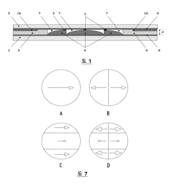
도 1은 본 발명의 한 실시예에 따른 광학 장치의 단면도이고;
도 2는 상기 장치의 온 상태와 오프 상태에서 액정의 방향을 도시하고;
도 3은 경사면들에서의 배향 방향의 효과를 도시하고;
도 4는 상기 경사면들을 보상하는 선경사를 도시하고;
도 5a 내지 도 5c는 상기 렌즈 표면의 다양한 위치에서 상기 액정 분자에 대한 선경사의 효과를 나타내는 렌즈 표면의 일부를 도시하고;
도 6은 부영역들로 나뉘고 상기 부영역들에 서로 다른 선경사가 적용된 렌즈 표면을 도시하고; 그리고
도 7은 렌즈 표면에 선경사를 가하는 다양한 방법을 도시한다.1 is a cross-sectional view of an optical device according to an embodiment of the present invention;
2 shows the orientation of the liquid crystal in the on and off states of the device;
3 shows the effect of the orientation direction on the slopes;
4 shows a pretilt that compensates for the inclined surfaces;
5A to 5C show a portion of the lens surface showing the effect of pretilt on the liquid crystal molecules at various positions on the lens surface;
6 shows a lens surface divided into sub-regions and different pretilts applied to the sub-regions; And
7 shows various methods of applying a pretilt to the lens surface.
이제 본 발명의 일부 바람직한 실시예를 도시한 도면을 참고하여, 본 발명은 보다 상세하게 설명될 것이다.Referring now to the drawings showing some preferred embodiments of the invention, the invention will be described in more detail.
도면에서, 동일한 참조 번호는 동일하거나 유사한 요소를 지칭한다.In the drawings, the same reference numbers refer to the same or similar elements.
본 발명은 특정 실시예 및 특정 도면을 참조하여 설명될 것이지만, 본 발명은 이에 한정되지 않는다. 설명된 도면은 단지 개략적이고 비한정적이다. 도면에서, 일부 구성 요소의 크기는 설명을 위해 과장되어 축소되지 않고 도시될 수 있다. 치수 및 상대 치수는 본 개시를 실시하기 위한 실제 구현에 반드시 대응할 필요는 없다.The invention will be described with reference to specific embodiments and specific drawings, but the invention is not limited thereto. The drawings described are only schematic and non-limiting. In the drawings, the size of some components may be exaggerated for illustration and not shown. Dimensions and relative dimensions do not necessarily correspond to actual implementations for practicing the present disclosure.
또한, 상세한 설명 및 청구 범위에서 제1, 제2, 제3 등의 용어는 유사한 요소를 구별하기 위해 사용되며 반드시 순차적 또는 시간 순서를 설명하는 것은 아니다. 상기 용어는 적절한 상황에서 상호 교환 가능하며, 본 개시의 실시예는 여기에 설명되거나 도시된 것과 다른 순서로 동작 할 수 있다.In addition, in the detailed description and claims, terms such as first, second, and third are used to distinguish similar elements and do not necessarily describe sequential or chronological order. The terms are interchangeable in appropriate circumstances, and embodiments of the present disclosure may operate in a different order than what is described or illustrated herein.
또한, 상세한 설명 및 청구 범위에서 상, 하, 상, 하 등의 용어는 설명의 목적으로 사용되며 반드시 상대 위치를 설명하기 위한 것은 아니다. 이와 같이 사용된 용어는 적절한 상황에서 상호 교환 가능하며, 여기에 설명된 본 발명의 실시 예는 여기에 설명되거나 도시된 것과 다른 방향으로 동작 할 수 있다.In addition, in the detailed description and claims, terms such as up, down, up, down, etc. are used for the purpose of description and are not necessarily used to describe relative positions. The terms used in this way are interchangeable in appropriate circumstances, and the embodiments of the invention described herein may operate in different directions than those described or illustrated herein.
청구 범위에 사용 된 용어 "포함하는"은 이후에 열거된 수단으로 제한되는 것으로 해석되어서는 안되며; 다른 요소나 단계를 제외하는 것이 아니다. 언급된 특징, 정수, 단계 또는 구성 요소의 존재를 특정하는 것으로 해석되어야 하지만, 하나 이상의 다른 특징, 정수, 단계 또는 구성 요소, 또는 이들의 그룹의 존재 또는 추가를 배제하지는 않는다. 따라서, "수단 A 및 B를 포함하는 장치"라는 표현의 범위는 구성 요소 A 및 구성 요소 B로만 구성된 장치로 제한되어서는 안된다. 이는 본 개시 내용과 관련하여, 장치의 유일한 관련 구성 요소는 A 및 B인 것을 의미한다. 청구항에 사용된 "적어도 하나의"라는 용어는 언급된 하나 이상의 언급 된 특징, 정수, 단계 또는 구성 요소의 존재를 명시함으로써 표현 및/또는 표현을 대체하는 것으로 해석되어야 한다. A 및 B 중 적어도 하나는 A 및/또는 B로 해석되어야 한다. 청구항에서 사용 된 용어 "하나"는 언급된 특징, 정수, 단계 또는 구성 요소 중 하나의 존재를 명시하는 것으로 해석되어야 한다. 이에 의해 표현을 '또는'과 대체되어야 한다. 따라서 A와 B 중 하나는 A 또는 B로 해석해야 한다.The term "comprising" as used in the claims should not be construed as being limited to the means listed thereafter; It does not exclude other elements or steps. It should be construed as specifying the presence of the recited features, integers, steps or components, but does not exclude the presence or addition of one or more other features, integers, steps or components, or groups thereof. Accordingly, the scope of the expression "apparatus comprising means A and B" should not be limited to devices consisting only of component A and component B. This means that in the context of the present disclosure, the only relevant components of the device are A and B. The term "at least one" as used in the claims should be construed as replacing a representation and / or representation by specifying the presence of one or more of the mentioned features, integers, steps or components mentioned. At least one of A and B should be interpreted as A and / or B. The term “one” used in the claims should be construed to indicate the presence of one of the mentioned features, integers, steps or components. In this way, the expression should be replaced with 'or'. Therefore, one of A and B should be interpreted as A or B.
열가소성 또는 열연화 플라스틱은 특정 온도 이상에서 유연하거나 성형 가능하고 냉각 시 고화되는 플라스틱 재료, 중합체이다. 바람직하게, 이들 열가소성 층들은 광학적으로 투명한 중합체, 즉 시각 스펙트럼, 예를 들어 400-700nm에서 5내지 100 %의 광 투과 효율을 갖는 중합체로 형성된다. 이러한 예로는 폴리에틸렌 테레프탈레이트(polyethylene terephthalate), 셀룰로오스 트리아세테이트(cellulose triacetate), 투명 폴리우레탄 폴리카보네이트(polyurethane polycarbonate), 또는 Mitsui MR8과 같이 안경 제조에 사용되는 티오우레탄(thiourethane) 재료등이다. 이들 재료로 형성된 필름은 5내지 1000㎛의 두께를 가질 수 있고 전형적으로 최대 3 mm의 굽힘 반경을 견딜 수 있다.Thermoplastic or hot-softened plastics are plastic materials, polymers that are flexible or moldable above a certain temperature and solidify upon cooling. Preferably, these thermoplastic layers are formed of an optically transparent polymer, i.e., a polymer having a light transmission efficiency of 5 to 100% in the visual spectrum, for example 400-700 nm. Examples include polyethylene terephthalate, cellulose triacetate, transparent polyurethane polycarbonate, or thiourthane materials used in the manufacture of glasses, such as Mitsui MR8. Films formed from these materials can have a thickness of 5 to 1000 μm and typically withstand a bending radius of up to 3 mm.
회절 광학 소자(DOE: diffractive optical element)는 블레이즈 격자, 프레넬 렌즈, 프레넬 액시콘 또는 투과된 광에서 미리 결정된 위상 프로파일을 유도하는 다른 구조물과 같은 회절 구조물을 포함 할 수 있다.Diffractive optical elements (DOEs) can include diffractive structures such as blaze gratings, Fresnel lenses, Fresnel axicons, or other structures that induce a predetermined phase profile in transmitted light.
공동(7)을 채우는 유체 물질은 액정 물질이다. 바람직하게, 공동을 채우는 상기 액정 물질의 굴절률은 액정 물질의 적어도 하나의 상태에 대하여 회절 광학 소자(4), 보더(border)(6), 접착제의 굴절률에 맞춰진다. 예를 들어, 공지의 액정 E7의 일반적인 지표는 자외선 글루 NOA 74와 같다. 액정 물질은 오프 상태에서 수직으로 배열된다. 수직 배향 액정 물질은 자연적으로 배향 표면에 수직으로 배향되는 물질이다. 달리 말하면, 전압이 가해지지 않을 때, 광학 장치의 오프 상태에서, 액정들은 배향 표면에 실질적으로 수직 방향으로 유지된다. 이러한 물질은 또한 음의 유전율 이방성(ε)을 갖는다는 것이 공지되어 있고, 그 자체가 공지되어 있다. 이러한 액정 물질은 또한 수직 배향으로 언급된다. 광학 장치의 아래 부분에서, 배향 표면은 회절 구조의 경사면들에 의해 주로 형성된다. 광학 장치의 윗 부분에서, 배향 표면은 제2 전극층 또는 제2 전극을 포함하는 다른 층에 의해 형성된다. 상부 배향막과 하부 배향막은 광학 장치의 공동의 하부 벽과 상부 벽을 이룬다. 한 실시예에서, 하부 배향 표면과 상부 배향 표면은 평행한 것이 아니라, 오히려 경사면들에 대응하는 경사진 부영역들로 보여진다.The fluid material filling the
수직 배향된 액정 물질들 내의 분자들은, 오프 상태에서, 전극층에 대하여가 아니라 배향 표면이 되는 접촉 표면에 대하여 실질적으로 수직인 위치를 취하는 것으로 알려져 있다. 본 발명의 광학 장치에서 이러한 결과는, 오프 상태에서, 액정들 중 적어도 일부가 제1 전극층에 대하여 기울어진 위치를 가지는 것이다. 이러한 틸트는 회절 구조에서 적어도 하나의 경사면의 기울기에 직접 관련된다. 따라서, 통상적으로, 전극층에 대한 이러한 틸트는 광학 장치에 걸쳐 불연속적이다. 뒤에서 할 설명에서, 제1 전극층의 법선에 대한 액정 분자들의 틸트는 유효 틸트 각도로 지칭된다. 도 4에서, 유효 틸트 각도는 도면 부호 β로 도시된다.It is known that molecules in vertically oriented liquid crystal materials, in the off state, take a position substantially perpendicular to the contact surface which becomes the alignment surface, not to the electrode layer. In the optical device of the present invention, this result is that, in the off state, at least some of the liquid crystals have a tilted position with respect to the first electrode layer. This tilt is directly related to the slope of at least one slope in the diffractive structure. Thus, typically, this tilt for the electrode layer is discontinuous across the optical device. In the description to be given later, the tilt of the liquid crystal molecules with respect to the normal of the first electrode layer is referred to as an effective tilt angle. In Fig. 4, the effective tilt angle is denoted by reference numeral β.
선경사의 개념은 액정 재료에 대해 알려져 있다. 문헌적으로는, 선경사라는 용어는 일반적으로 상황에 따라 약간 다른 정의를 가질 수 있다. 본 명세서에서는, 수직 배향 액정 물질이 사용되고, 배향층은 전극층들에 대한 서로 다른 기울기 방향들 및/또는 서로 다른 각도를 불연속적으로 나타낸다. 이 명세서 내에서 선경사는, 장치의 오프 상태에서, 액정 분자들과 배향 물질의 표면 법선 사이의 각도에 관련한 것으로 정의된다. 배향 물질은 액정 분자들이 접촉하는 물질이다. 도 4에서, 선경사는 도면 부호 α로 도시된다. 이러한 정의에 따르면, 배향 표면이 제1 전극층과 평행일 때, 유효 틸트 각도(β)와 선경사(α)는 같다. 이는 도 4에서 도면의 가운데 부분에 도시된다. 따라서, 이 정의에 따르면, 선경사가 가해지지 않을 때, 액정 분자들은 배향 표면에 대해 실질적으로 수직을 이루도록 뻗어 있다.The concept of pretilt is known for liquid crystal materials. Literally, the term pretilt can have a slightly different definition in general, depending on the situation. In this specification, a vertically oriented liquid crystal material is used, and the alignment layer discontinuously shows different tilt directions and / or different angles to the electrode layers. Within this specification, the pretilt is defined as related to the angle between the liquid crystal molecules and the surface normal of the alignment material, in the off state of the device. The alignment material is a material in which liquid crystal molecules contact. In FIG. 4, the pretilt is indicated by the reference numeral α. According to this definition, when the orientation surface is parallel to the first electrode layer, the effective tilt angle β and the pretilt α are the same. This is shown in the middle of the figure in FIG. 4. Thus, according to this definition, when no pretilt is applied, the liquid crystal molecules are stretched to be substantially perpendicular to the alignment surface.
액정 분자에 선경사를 제공하기 위한 다양한 기술들이 문헌에서 설명되어 있다. 이러한 기술들 대부분의 목표는 액정 분자들을 소정의 방향을 향하도록 하는 것이다. 이는 온 상태로 상태가 변화할 때, 액정 분자들의 회전하는 방향에 영향을 준다. 대부분의 광학 시스템에서, 이러한 액정 분자들은 단일 방향을 향하는 것이 바람직하다. 이를 통해, 많은 경우에서, 선경사는 각도를 정의할 뿐만 아니라 각도가 향하는 방향도 정의하는 것이 자명하다. 예를 들어, 러빙을 통해 선경사가 실현될 때, 러빙 방향은 선경사 방향을 결정하고, 러빙 세기는 선경사 각도를 결정한다.Various techniques for providing pretilt to liquid crystal molecules have been described in the literature. The goal of most of these techniques is to direct the liquid crystal molecules in a predetermined direction. This affects the direction in which the liquid crystal molecules rotate when the state changes to the on state. In most optical systems, it is desirable that these liquid crystal molecules face a single direction. Through this, in many cases, it is obvious that the pretilt not only defines the angle but also the direction in which the angle is directed. For example, when the pretilt is realized through rubbing, the rubbing direction determines the pretilt direction, and the rubbing intensity determines the pretilt angle.
완벽함을 가하기 위해, 빛샘이라고 불리는 효과를 포함하는, 광학 장치에서의 액정 분자들의 광학적 효과가 설명된다. 전체 회절 구조에 걸쳐 하나의 편광에 대한 균일한 광학 응답을 보장하기 위해, 네마틱 액정 분자들은 모든 상태에서 단일축으로 정렬된 상태로 유지하여야 한다. 이러한 방식에서, 복굴절 분자에 의해 야기된 위상차이는 두 특정 수직 배향에서 선형으로 편광된 빛의 편광에 영향을 미치지 않을 것이다. 투과된 빛의 위상 프로파일이, 예를 들어 다양한 위치에서의 회절 구조의 높이에 의해 영향을 받을 때, 한 포인트에 초점을 맞추는 것과 같은 특정 양상을 나타내도록 주의깊게 관리될 수 있다. 단축 방향에 평행한 선형 편광된 빛은 선형 편광된 상태를 유지하지만, 위상 프로파일은 변경되고, 반면에 수직 방향은 영향을 받지 않는다. 보정 배향을 갖는 액정 셀 앞에 선형 편광자를 배치하거나(전체 광 투과율은 감소시키는 대신), 또는 90도 각도로 두 개의 동일한 셀을 배치함으로써 원하는 응답을 갖는 광학 장치를 구성 할 수 있고, 이는 편광 무의존 장치를 초래한다.To add perfection, the optical effect of liquid crystal molecules in an optical device, including an effect called light leakage, is described. In order to ensure a uniform optical response to a single polarization across the entire diffraction structure, nematic liquid crystal molecules must be kept uniaxially aligned in all states. In this way, the phase difference caused by birefringent molecules will not affect the polarization of linearly polarized light in two specific vertical orientations. The phase profile of the transmitted light can be carefully managed to reveal a particular aspect, such as focusing on a point, when affected by the height of the diffractive structure at various locations, for example. Linearly polarized light parallel to the minor axis remains linearly polarized, but the phase profile is altered, while the vertical direction is unaffected. An optical device with a desired response can be constructed by placing a linear polarizer in front of a liquid crystal cell with a corrected orientation (instead of reducing the overall light transmittance), or by placing two identical cells at an angle of 90 degrees, which is polarization independent Effect device.
그러나, 분자 배향이, 예를 들어 회절 구조의 표면으로 인해, 일축 구성으로부터 벗어나면, 위치에 의존하는 지연(retardation)이 발생한다. 이 결과로, 편광에서 위치에 따른 변화가 일어날 것이고, 국지적 위상 프로파일이 두 상태의 중첩 상태가 될 것이다. 완벽한 일축 배향과는 달리, 선형 편광기는 전체 장치에 걸쳐 원하지 않는 위상 프로파일을 제거 할 수 없고, 이에 따라 위치에 의존하는 이중 이미지가 발생한다. 유사하게, 두 개의 이러한 같은 장치들은 위치에 의존하는 이중 이미지를 가져온다. 이 효과는 빛샘으로 불리며, 본 발명에 의해 최소화된다.However, if the molecular orientation deviates from the uniaxial configuration due to, for example, the surface of the diffractive structure, position-dependent retardation occurs. As a result of this, there will be a positional change in polarization, and the local phase profile will be a superposition of the two states. Unlike a perfect uniaxial orientation, linear polarizers cannot remove unwanted phase profiles across the entire device, resulting in a location-dependent dual image. Similarly, two of these same devices result in a location-dependent dual image. This effect is called light leakage and is minimized by the present invention.
바람직하게, 하부 기판은 제1 광학 투명 열가소성 층(2)을 포함하고, 제1 광학 투명 전극(8)을 포함한다. 상부 기판은 제2 광학 투명 열가소성 층(3)을 포함하고, 제2 광학 투명 전극(9)을 포함한다. 두 층들(2, 3)은, 고정된 간격(d)을 이루도록 제공되고, 고정된 간격(d)은 바람직하게 회절 광학 요소(4)의 상부에 제공되는 복수의 스페이서(5)에 의해 설정된다. 이 간격은 바람직하게 보더(6)에 의해 추가적으로 유지된다. 도 1에 도시한 바와 같이, 회절 광학 요소(4), 스페이서들(5), 그리고 보더(6)는 두 층들(2, 3) 사이, 그리고 두 전극층(8, 9) 사이에 위치한다. 상기 간격(d)은 10나노미터(nm) 내지 100마이크로미터(μm), 통상적으로 50nm 내지 50 μm 사이의 값일 수 있다.Preferably, the lower substrate comprises a first optically transparent
바람직한 실시예에서, 보더(6), 스페이서(5), 회절 광학 요소(4)는 서로 같은 물질 조성을 가진다. 예를 들어, 스페이서(5), 회절 광학 요소(4)와 보더(6)는 비스페놀 플루오르 디아크릴레이트(bisphenol fluorine diacrylate)와 같은 고 굴절률 모노머 또는 Norland Optical Adhesives (NOA)와 같은 Products, Inc 사에서 시판되는 NOA 1625 또는 NOA 164와 같은 고 굴절률 UV 접착제로 제조 될 수 있다.In a preferred embodiment, the
뒤에서 설명하는 바와 같이, 보더(6), 스페이서(5), 회절 광학 요소(4)는 앞에서 언급한 물질을 포함하는 하나의 층을 하부 기판 위에 형성한 후 나노임프린트 기술을 이용하여 형성될 수 있다.As described later, the
나노임프린트 기술은, 반도체와 평판 패널의 제조 방법에서 이용되는 사진 식각 패터닝 기술과 비교하여, 단순하고, 저비용이고, 대량 생산 가능한 패터닝 기술이다. 참고 문헌으로 인용된, Kooy et al의 'A review of roll-to-roll nanoimprint lithography'에 공개된 바와 같이, 나노 임프린트 리소그라피는 원하는 패턴과 역의 형태를 포함하는 조립식 몰드의 사용을 포함한다. 이러한 몰드가 폴리머가 증착된 기판 위를 눌러, 기계적 변형에 의해 폴리머에 패턴이 복사된다. 변형 후, 변형된 중합체에 열 공정을 가하거나, 변형된 중합체에 자외선 광을 가함으로써, 나노 임프린트된 패턴을 경화함으로써, 패턴은 고정된다. 다음으로, 몰드가 제거된다. 반대 패턴은 형성될 단일 구조에 대응할 수 있다. 폴리머 내에 배열된 구조들을 형성한 후, 필요한 구조의 수만큼 나노 임프린트 공정을 반복해야 한다. 몰드가 배열된 역 패턴을 포함하는 경우, 처리량이 증가 될 수 있으며, 이에 의해 한번의 나노 임프린트 동안 같은 폴리머 내에 원하는 수의 구조가 동시에 형성된다.The nanoimprint technology is a simple, low-cost, and mass-producible patterning technology compared to the photolithography patterning technology used in semiconductor and flat panel manufacturing methods. As published in Kooy et al's 'A review of roll-to-roll nanoimprint lithography', cited by reference, nanoimprint lithography involves the use of prefabricated molds that include the desired pattern and inverse morphology. The mold is pressed onto the substrate on which the polymer is deposited, and the pattern is copied to the polymer by mechanical deformation. After deformation, the pattern is fixed by applying a thermal process to the modified polymer or curing the nanoimprinted pattern by applying ultraviolet light to the modified polymer. Next, the mold is removed. The opposite pattern can correspond to a single structure to be formed. After forming the structures arranged in the polymer, the nanoimprint process must be repeated as many times as necessary. If the mold includes an inverted pattern arranged, the throughput can be increased, whereby a desired number of structures are simultaneously formed in the same polymer during one nanoimprint.
바람직하게, 제2 열가소성층(3)을 향해 배향된 회절 광학 요소(4)의 표면은 액정 재료를 위한 정렬 층으로서 구성된 초미세(1마이크로 미만의) 홈(groove)들을 포함한다. 이러한 홈들은 앞서 설명한 나노임프린트에 의해 회절 광학 요소(4)를 형성할 때 제조된다. 나노임프린트 공정에서 사용된 몰드는 보더(6), 스페이서(5), 회절 광학 요소(4)의 음의 형태를 포함할 뿐만 아니라, 내부 표면에는 적어도 회절 광학 요소(4)의 위치에, 예를 들어 원형 또는 사각 패턴의 홈들을 포함한다. 이러한 시도는 통합된 방식으로 이러한 구조를 형성하는 것이 가능하다. 'Molecular-Scale Soft Imprint Lithography for Alignment'에서 R. Lin et al.가 개시한 바와 같이, Y.J. Liu et al는 'Nanoimprinted ultrafine line and space nano- gratings for liquid crystal alignment'에서 나노 임프린트 기술을 이용하여 배향 패턴들을 형성하는 것을 개시한다.Preferably, the surface of the diffractive
액정 재료의 배향 특성은 홈 자체의 기하학적 구조뿐만 아니라 홈이 형성되는 회절 광학 소자(4)를 구성하는 재료에 의해서도 결정된다. 만일 같은 구조의 홈을 위해 다른 물질이 이용된다면, 다른 물질의 정렬 특성을 제공하기 위해, 이러한 그루브 위에 추가적인 컨포멀(conformal) 배향막이 형성될 수 있다. 예를 들어, 회절 광학 소자의 재료가 평면 방식으로 액정 분자를 정렬시키는 경우, 적어도 일부의 홈들을 덮는 수직 배향막이 코팅 될 수 있다. 이러한 컨포멀 배향막은 회절 광학 소자(4)의 홈을 가지는 표면 전체를 덮을 수 있다. 대안적으로, 이러한 홈을 가지는 표면 중 일부분만 추가적인 컨포멀 배향막에 의해 덮이는 경우, 추가적인 컨포멀 배향막과 회절 광학 소자(4) 사이의 물질 배향 특성들의 차이를 이용할 수 있다. 회절 광학 소자(4) 위에 위치하는 공동(7) 내부에 평탄화 물질의 층이 존재할 수 있다. 제2 열가소성 층(3)을 향하도록 배향된, 평탄화 층의 표면에 형성된 홈들에 의해, 배향막은 공동(7)의 하부에도 역시 존재할 수 있다. 장치(1)의 동작 동안, 이러한 홈들은 공동(7)에 존재하는 액정들의 배향을 돕는다. 바람직하게, 제2 열가소성 층(3)에 인접하여 홈을 가지는 표면과 마주하는 공동(7)의 측면에, 추가적인 배향막이 또한 위치할 수 있다.The alignment property of the liquid crystal material is determined not only by the geometry of the groove itself, but also by the material constituting the diffractive
회절 광학 소자(4)와 평탄화 층의 각각의 물질들은, 적어도 그들 사이의 경계에서, 같은 굴절률을 가질 수 있다. 또한, 낮은 주파수(예를 들어, 10Hz 내지 10kHz)의 전기장에서 이러한 물질들의 유전율은 다를 수 있다. 이러한 평탄화 물질은 보더(6)의 상부 부분을 형성하는데 또한 사용될 수 있다. 만일 노치(16)가 존재한다면, 이 역시 평탄화 물질로 형성된다.The respective materials of the diffractive
광학 투명 전극은 ITO(Indium Tin Oxide), ClearOhm® 은(Ag) 나노와이어, 또는 AGFA Orgacon 잉크와 같은 재료로 만들어질 수 있다. ITO의 취약성(brittleness)으로 인해, PEDOT: PSS, 그래핀, 탄소 나노 튜브 또는 은 나노와이어와 같이 덜 단단하고 더 유연한 재료가 사용될 수 있다. 광학 투명 전극(8, 9)은 회절 광학 요소(4)의 다른 구역들을 개별적으로 처리하도록 패턴화 될 수 있다. 이 전극은 전체 용량을 줄이기 위해, 회절 광학 소자(4)의 영역 내에 전극만을 갖도록 하거나, 또는 이 영역 내의 전극을 경계 영역 내의 전극으로부터 분리함으로써, 패턴화될 수도 있다.The optically transparent electrode can be made of a material such as Indium Tin Oxide (ITO), ClearOhm® silver (Ag) nanowire, or AGFA Orgacon ink. Due to the brittleness of ITO, less rigid and more flexible materials such as PEDOT: PSS, graphene, carbon nanotubes or silver nanowires can be used. The optically
본 개시의 제2 측면에서, 앞선 측면에서 개시된 바와 같이 광학 장치(1)는 광학 기기에 사용된다. 광학 기기에 삽입될 때, 광학 장치(1)는 눈을 향한 빛의 위상 프로파일을 조정하도록 구성된다.In a second aspect of the present disclosure, the optical device 1 is used in an optical instrument as disclosed in the preceding aspect. When inserted into the optical instrument, the optical device 1 is configured to adjust the phase profile of the light towards the eye.
이러한 광학 기기는 렌즈일 수 있고, 광학 장치는 렌즈 삽입으로 사용된다. 안과에서의 적용을 고려할 때, 렌즈는 안경 렌즈, 콘택트 렌즈 또는 안내 렌즈일 수 있다. 안경 렌즈 및 콘택트 렌즈는 일반적으로 메니스커스 형상을 갖기 때문에, 광학 장치(1)가 내장될 렌즈의 곡률과 실질적으로 동일한 곡률로 만곡될 때, 광학 기기는 렌즈에보다 쉽게 통합 될 수 있다. 전형적으로, 광학 장치는 두 개의 직교 방향으로 만곡될 것이다. 안내 렌즈의 경우, 평면 또는 곡면 광학 장치가 내장 될 수 있다.Such an optical device may be a lens, and the optical device is used as a lens insertion. Considering application in ophthalmology, the lenses can be spectacle lenses, contact lenses or intraocular lenses. Since the spectacle lens and the contact lens generally have a meniscus shape, when the optical device 1 is curved at a curvature substantially equal to the curvature of the lens to be built in, the optical device can be more easily integrated into the lens. Typically, the optical device will be curved in two orthogonal directions. In the case of an intraocular lens, a planar or curved optical device may be incorporated.
이러한 광학 기구는 하나 이상의 광학 장치(1)를 포함 할 수 있다. 복수의 이러한 광학 장치(1)들이 적층될 수 있다. 복수의 광학 장치들을 적층함으로써, 하나의 광학 장치의 전기 광학적 특성이 조합될 수 있다. 예를 들어, 네마틱 액정으로 채워지고, 수직으로 배향된 두 개의 장치들은 편광 무의존 조절가능 렌즈를 야기한다. 도 2는 온/오프 상태 사이에서 잘 제어된 굴절률 차이를 생성하기 위한 액정 분자(10)의 의도된 거동을 도시한다. 이러한 제어된 차이는 광학 장치의 바람직한 신뢰성 있는 광학 특성을 야기한다. 도면에서, 오프 상태의 액정 분자는 10a로 지칭되고, 온 상태의 액정 분자는 10b로 지칭된다. 오프 상태에서, 액정 분자는 수직 배향된다.Such an optical instrument can include one or more optical devices 1. A plurality of such optical devices 1 can be stacked. By stacking a plurality of optical devices, the electro-optical properties of one optical device can be combined. For example, two devices filled with nematic liquid crystal and oriented vertically result in a polarization-independent adjustable lens. 2 shows the intended behavior of the
액정 분자들을 포함하는 광학 장치는 그 온 상태와 오프 상태에서 액정의 굴절률 차이에 의해 동작한다. 이는 액정 분자의 배향 변화의 결과이며, 조심스럽게 제어하지 않으면 렌즈가 오작동하게 된다. 특히, 오프 상태에서, 대부분의, 바람직하게는 모든 액정 분자들이 위쪽을 향하는 것이 바람직하다. 이 상태에서, 액정의 굴절률은 렌즈의 수지 재료의 굴절률과 실질적으로 일치된다. 이는 사용된 액정 혼합물의 일반적인 굴절률(ne)이 렌즈 물질의 굴절률과 실질적으로 동일함을 의미한다. 이러한 일치는 모든 파장의 가시 광선에 대해 충분한 방식으로 이루어진다. 따라서, 렌즈를 제조하기 위한 수지 재료는 액정 혼합물의 분산 곡선과 매우 유사한 굴절률 분산 곡선을 가지도록 준비되어, 이 둘의 굴절률은 0.05이상으로 차이나지 않는다.An optical device including liquid crystal molecules operates by a difference in refractive index of liquid crystal in its on and off states. This is a result of the change in the orientation of the liquid crystal molecules, and if not carefully controlled, the lens may malfunction. In particular, in the off state, it is preferable that most, preferably all liquid crystal molecules face upward. In this state, the refractive index of the liquid crystal substantially matches the refractive index of the resin material of the lens. This means that the general refractive index (ne) of the liquid crystal mixture used is substantially the same as that of the lens material. This match is made in a sufficient way for all wavelengths of visible light. Therefore, the resin material for manufacturing the lens is prepared to have a refractive index dispersion curve very similar to the dispersion curve of the liquid crystal mixture, so that the refractive index of the two does not differ by more than 0.05.
전기장이 인가될 때, 액정 분자의 대부분, 바람직하게는 모든 액정 분자는 실질적으로 수평으로 정렬되고, 모두 소정의 축에 실질적으로 평행하게 연장되고, 보다 바람직하게는 실질적으로 동일한 방향을 가리키는 것이 바람직하다. 이러한 방식으로, 단지 하나의 편광에 대하여 광학적 출력이 있으며, 상부 배향막과 하부 배향막 모두가 조정된 방식으로 작용한다. 이 광학적 출력을 실제로 사용하기 위해서, 일반적인 굴절률과 특별한 굴절률의 차이가 일반적으로 > 0.15 정도 커야 한다.When an electric field is applied, it is preferred that most of the liquid crystal molecules, preferably all liquid crystal molecules are substantially horizontally aligned, all extend substantially parallel to a given axis, and more preferably point in substantially the same direction. . In this way, there is an optical output for only one polarization, and both the upper alignment layer and the lower alignment layer function in a coordinated manner. In order to actually use this optical power, the difference between a typical refractive index and a special refractive index should generally be> 0.15.
도 1은 본 발명의 광학 장치의 단면도를 도시한다. 도 1에서는 서로 다른 기울기 방향 및/또는 서로 다른 기울기 각도들을 가지는 복수의 경사면들(11)을 포함하는 회절 구조를 도시한다. 프레넬 렌즈는 매우 대칭적이다. 따라서, 경사면들(11)은 다른 기울기 각도들을 가질 수 있다. 바람직한 배향 방향(12)과 같은 방향으로 기울어진 경사면은 도면 부호 11a로 도시한다. 바람직한 배향 방향(12)과 반대의 방향으로 기울어진 경사면은 도면 부호 11b로 도시한다. 도 4는 편평한 표면(11c)을 더 도시한다. 본 발명에 따르면, 이러한 회절 구조를 가지는 광학 장치에서, 도 2에 도시한 바와 같은 양상을 얻기 위하여, 액정 분자들의 선경사가 변경된다. 선경사의 변화가 없는 액정 물질의 양상은 도 3에 도시된다.1 shows a cross-sectional view of the optical device of the present invention. 1 shows a diffractive structure including a plurality of
바람직하게, 광학 장치들은 폴리이미드 내에 바람직한 배향 방향(12)을 가지도록 형성된다. 이를 통해, 빛의 한 편광 방향의 파워가 집중되고 나머지 하나는 변경되지 않는다. 한 실시예에 따르면, 렌즈 층 표면이 아니라 양쪽 렌즈 위에 위치하는 폴리이미드 층들을 역방향으로 러빙함으로써 달성된다. 같은 결과를 가져오는 다른 기술이 또한 사용될 수 있음은 자명하다.Preferably, the optical devices are formed to have a preferred
데스트 동안, 바람직한 배향 방향을 이루기 위한 이 기술은 낮은 광학 파워를 가지는 렌즈에 적절하게 작동하는 것이 관찰되었다. 달리 말하면, 중간 또는 낮은 구조들을 가지는 회절 구조들이 사용될 때, 이 기술은 적절하게 작동한다. 그러나, 고파워 렌즈에서, 전기장이 가해졌을 때, 매우 많은 수의 디스클리네이션이 발생하였다.During the test, it has been observed that this technique for achieving the preferred orientation direction works properly for lenses with low optical power. In other words, when diffractive structures with medium or low structures are used, this technique works properly. However, in a high power lens, when an electric field was applied, a very large number of disinfections occurred.
본 발명은 표면 높낮이가 액정 분자들을 추가적으로 회전시켜, 전기장이 가해졌을 때, 액정 분자들(본질적으로 쌍극자를 가지는)이 반대 방향에 있는 렌즈에서 반대 방향으로 회전할 수 있다는 이해를 적어도 부분적으로 기초로 한다. 상부면과 하부면에서 액정 쌍극자가 반대의 방향으로 회전하는 측면에서 특히, 디스클리네이션의 원인이 된다. 이러한 원하지 않는 양상은 도 3에 도시되고, 아래에서 보다 상세히 설명된다. 이러한 원하지 않는 효과는 렌즈 측면의 기울기가 높거나, 렌즈의 파워와 직경이 커질 때 더욱 뚜렷해진다. 이러한 디스클리네이션은 외부의 가장 가파른 블레이즈들에서 렌즈들의 같은 면에서 전형적으로 발생한다.The present invention is based, at least in part, on the understanding that when the height of the surface further rotates the liquid crystal molecules, when an electric field is applied, the liquid crystal molecules (essentially having dipoles) can rotate in the opposite direction from the lens in the opposite direction. do. In particular, in the side where the liquid crystal dipole rotates in opposite directions on the upper surface and the lower surface, it causes a disinfection. This undesirable aspect is illustrated in FIG. 3 and described in more detail below. This unwanted effect becomes more pronounced when the slope of the lens side is high, or when the power and diameter of the lens is increased. This disclination typically occurs on the same side of the lenses in the steepest blazes outside.
도 3은 이러한 상황을 도시한다. 도 3의 중앙에 도시한 바와 같이, 광학 장치는 도면에서 오른쪽을 향해 바람직한 선경사 방향(12)을 가지도록 처리된다. 광학 장치의 회절 구조는 프레넬 렌즈이다. 도면의 왼쪽에, 광학 장치의 왼쪽면에서의 경사 부영역(11a)의 단면도를 도시한다. 도면의 오른쪽에, 광학 장치의 오른쪽면에서의 추가 경사 부영역(11b)의 단면도를 도시한다. 도 3에 도시한 바와 같이, 이러한 경사 부영역들은 반대의 경사 배열을 가짐이 자명하다.3 shows this situation. As shown in the center of FIG. 3, the optical device is processed to have a preferred
또한 도 3은, 그 양쪽에서, 상부와 하부의 상태를 도시한다. 상부 상태는 액정 분자들이 서는 상태(10a)에 대응하고, 하부 상태는 액정 분자들이 눕는 상태(10b)에 대응한다. 서는 상태는 전극들 사이에 주요한 전기장이 가해지지 않았을 때, 액정 분자들이 취하는 상태를 말한다. 눕는 상태는 전극들 사이에 소정의 전기장이 가해졌을 때, 액정 분자들이 취하는 상태를 말한다.Fig. 3 also shows the upper and lower states on both sides. The upper state corresponds to the
바람직한 배향 방향의 결과로, 도 3에 도시한 바와 같이, 액정 분자들의 대부분은 눕는 상태(10b)에서 오른쪽을 향하는 경향이 있다. 그러나, 도면의 우측에서의 기울기 각도는, 도면 부호 10b로 도시된 바와 같이, 경사면의 근접에 위치하는 액정 분자들이 좌측으로 향하도록 영향을 미친다. 도면의 우측과 하부에서 액정 분자의 일부(10bb)는 좌측으로 향하고 액정 분자의 다른 일부(10b)는 우측으로 향하는 것을 도시한다. 본 개시에서, 공동의 가장자리에서의 액정 분자들의 배열은 전체 액정 셀로 확장될 것을 추론할 수 있다. 일반적으로, 전체 액정 셀 내에서 일치하지 않는 배열을 보상하기 위해, 액정분자들에게 추가적으로 비틀림(twist)이 발생하게 된다. 이는 액정 분자들을 통해 투과된 빛을 변화시켜, 광학 장치에서 광학적 오류가 시인된다.As a result of the preferred orientation direction, as shown in Fig. 3, most of the liquid crystal molecules tend to face to the right in the lying
이러한 문제의 해결을 위해, 표면의 높낮이에 의해 설정되는 틸트를 보상하도록, 배향 물질의 표면에 대한 액정 분자의 선경사를 변화시킨다. 이러한 선경사는 액정 물질의 공지된 특성으로, 액정 분자들과 배향 물질(11)의 표면 법선 사이의 각도를 의미한다. 간략하게 설명하면, 액정의 선경사를 기울기보다 더 크게 하면, 액정 분자들은 같은 방향으로 배열되고, 의도된 배향 동작이 달성될 수 있다. 이는 도 4에서 도시된다. 도 4는 선경사의 원리를 도시한다. 도면은 서로 다른 기울기 각도들을 가지는 표면 위의 액정 분자와 표면 법선 사이의 각도를 나타낸다.To solve this problem, the pretilt of the liquid crystal molecules with respect to the surface of the alignment material is changed to compensate for the tilt set by the height of the surface. This pretilt is a known property of the liquid crystal material, and means the angle between the liquid crystal molecules and the surface normal of the
도 4로부터, 각도(β)로 도시한 바와 같이, 액정 분자들(10a)의 절대 경사(tilt)가 바람직한 배향 방향(12)에 대응하도록, 선경사가 선택될 수 있음이 자명하다. 달리 말하면, 모든 액정 분자들(10a)는, 오른쪽 위를 향하는 상태에서, 절대 틸트(β)와 같은 방향을 가지도록 배열된다. 이를 달성하기 위하여, 선경사는 가장 가파른 대향 경사면 각도보다 큰 각도를 갖도록 선택된다. 이는 도 4의 오른쪽에 도시되어 있고, 경사면(11b)은 수직축에 대해 선경사 각도와 반대 방향의 각도를 가지는 표면 법선을 가진다. 선경사 각도(α)는 수직 방향과 표면 법선 사이의 각도보다 크고, 결과적인 절대 틸트(β)는 원하는 방향이 된다. 전기장이 가해짐에 따라 액정층이 활성화되면, 모든 액정 분자들은 모두 오른쪽 방향으로 회전하여 도 3에 도시한 상황을 피하게 되고 신뢰할 수 있는 광학 성능을 얻게 된다.It is apparent from FIG. 4 that the pretilt can be selected so that the absolute tilt of the
프리 틸트를 변경하기 위하여, 표면을 러빙할 때의 강도를 증가시키거나(Stohr et al, 'Microscopic Origin of Liquid Crystal Alignment on Rubbed Polymer Surfaces') 또는 감광성 배향 물질을 이용하거나(Yaroshchuk et al, 'Photoalignment of liquid crystals: basics and current trends'), 수직 배향된 액정과 수평 배향된 액정 물질을 혼합하거나(Wu et al., 'Controlling pretilt angles of liquid crystal using mixed polyimide alignment layer'), 다른 문헌에 설명된 다른 방법을 이용할 수 있다. 렌즈의 위치에 따라(예를 들어, 감광성 물질을 이용하여) 선경사 각도를 선택적으로 조절하여, 프레넬 렌즈 전체에 걸쳐 절대 틸트 각도를 같게 유지하는 것이 가능하다.To change the pre-tilt, increase the strength when rubbing the surface (Stohr et al, 'Microscopic Origin of Liquid Crystal Alignment on Rubbed Polymer Surfaces') or use a photosensitive alignment material (Yaroshchuk et al,' Photoalignment of liquid crystals: basics and current trends'), mixing vertically oriented liquid crystals and horizontally oriented liquid crystal materials (Wu et al., 'Controlling pretilt angles of liquid crystal using mixed polyimide alignment layer'), or described in other literature. Other methods can be used. It is possible to selectively adjust the pretilt angle according to the position of the lens (eg, using a photosensitive material) to maintain the same absolute tilt angle throughout the Fresnel lens.
다른 방법은 측면(facet)들의 기울기를 제한하는 것이다. 이는 특정 렌즈 파워를 위해 렌즈의 비구면 설계를 사용하거나, 기울기가 선경사보다 큰 반쪽 렌즈의 외부 부분을 제거(예를 들어, 타원형 렌즈 형성)하여 이루어질 수 있다.Another way is to limit the slope of the facets. This can be done by using the aspherical design of the lens for a particular lens power, or by removing the outer portion of the half lens with a slope greater than the pretilt (eg forming an oval lens).
도 5a는 렌즈 표면의 일부의 사시도를 나타낸다. 이 부분은 위에서 설명한 회절 광학 요소(4)의 가운데 부분일 수 있다. 도면에서, 표면 법선은 렌즈 표면의 다양한 위치에 도시된다. 이 표면 법선은 실선의 화살표로 도시되고, 도면 부호 N으로 도시된다. 앞서 설명한 바와 같이, 오프 상태에서 액정의 배열은 표면 법선과 선경사의 조합이다. 이러한 렌즈 표면의 복수의 위치에서의 액정 배열을 나타내는 벡터가 도시되어 있고, 도면 부호 Np로 도시된다. 액정 방향 벡터는 점선 화살표로 도시된다. 액정 방향 벡터는 오프 상태에서 액정 분자들의 배열에 관련된다. 선경사 각도는 α로 도시되고, 표면 법선(N)과 액정 방향 벡터(Np) 사이의 각도이다.5A shows a perspective view of a portion of the lens surface. This part can be the center part of the diffractive
앞서 설명한 바와 같이, 유효 틸트 각도(β)는 제1 전극의 표면 법선과 액정 배열 사이의 각도로 정의된다. 도 5a 내지 도 5c에서, 제1 전극의 표면 법선은 도면 부호 13으로 도시된다. 유효 틸트 각도(β)는 액정 분자와 표면 법선(13) 상의 각도로 보여진다.As described above, the effective tilt angle β is defined as the angle between the surface normal of the first electrode and the liquid crystal array. 5A to 5C, the surface normal of the first electrode is indicated by 13. The effective tilt angle β is shown as the angle on the liquid crystal molecule and the surface normal 13.
유효 틸트 각도(β)는 렌즈가 활성화될 때, 액정 분자들의 배열 방향을 결정한다. 액정 분자들의 배열 방향에서, 유효 틸트 각도(β)의 효과는 제1 전극층에 평행한 표면 위로 투영된 액정 방향 벡터(Np)에 의해 가장 잘 설명된다. 일반적으로, 배향 방향(12)은 제1 전극층과 평행하게 정의된다. 액정 방향 벡터(Np)를 이러한 표면 위로 투영한 부분은 도 5a 내지 도 5c에서 도면 부호 Npxy로 도시된다. 투영부(Npxy)는 배향 방향(12)과 나란한 성분과 배향 방향(12)을 가로지르는 성분을 포함한다. 렌즈 표면 위의 위치에 따라 가로지르는 성분은 0일 수 있음이 자명하다. 특히, 배향 방향에 가로지르는 방향에 대하여 경사면이 기울어지지 않는 경우, 투영부(Npxy)의 가로지르는 성분은 0이다.The effective tilt angle β determines the orientation of the liquid crystal molecules when the lens is activated. In the arrangement direction of the liquid crystal molecules, the effect of the effective tilt angle β is best explained by the liquid crystal direction vector Np projected onto a surface parallel to the first electrode layer. Generally, the
도 5a 내지 도 5c에서, 각도(θ)는 투영부(Npxy)와 배향 방향(12) 사이의 각도를 나타내는데 사용된다. 실험을 통해, 실질적으로 전체 정렬 표면에 걸쳐서, 각도(θ)가 60도 보다 작고, 보다 바람직하게는 45도 보다 작고, 가장 바람직하게는 30도 보다 작을 때, 렌즈 장치의 신뢰성 있고 예측 가능한 동작을 가져옴을 알 수 있었다. 도면을 참고하여 위에서 설명한 바를 기초하면, 당업자는, 선경사를 증가시키거나 및/또는 기울기 각도를 감소시킴으로써, 각도(θ)를 작게 만들 수 있음을 알 수 있을 것이다.5A to 5C, the angle θ is used to indicate the angle between the projection portion Npxy and the
도 5b는 같은 렌즈 표면의 제1 전극 층에 평행한 평면도로, 도 5a와 같은 구성은 같은 화살표로 표시된다. 따라서, 도 5b는 제1 전극층 위의 액정 분자들의 투영부들(Npxy)을 도시한다. 도 5b는 또한, 표면 법선(N)을 도시한다. 도 5b에서, 각도(θ)가 명확하게 도시될 수 있다. 도시한 바와 같이, 렌즈의 중앙선 위로 투영된 투영부의 경우 각도(θ)는 0이다. 렌즈의 아래 부분 위로 투영된 투영부의 경우, 각도(θ)는 약 30도이다. 도 5c는 같은 렌즈 표면의 측면도로, 도 5a 및 도 5b와 같은 구성은 같은 화살표로 표시된다. 도 5c로부터, 유효 틸트 각도(β)는 모든 액정 방향 벡터(Np)가 도면의 오른쪽을 향하도록 하는 것임이 명확하다. 결과적으로, 액정 방향 벡터(Np)는 모두 배향 방향에 대해 양의 벡터 성분을 가진다. 당업자는 이들 벡터가 도면의 오른쪽을 가리키는 효과는 액정 분자가 활성화 될 때 액정 분자가 오른쪽을 향할 것이라는 점을 알 수 있을 것이다. 이에 따라, 활성화 될 때 액정 분자의 균일한 반응을 일으키고, 이는 앞서 설명한 바와 같이, 유리하다.5B is a plan view parallel to the first electrode layer on the same lens surface, and the configuration as in FIG. 5A is indicated by the same arrow. Accordingly, FIG. 5B shows projections Npxy of liquid crystal molecules on the first electrode layer. 5B also shows the surface normal N. In Fig. 5B, the angle [theta] can be clearly shown. As shown, the angle θ is 0 for the projection projected over the center line of the lens. For the projection projected over the lower part of the lens, the angle θ is about 30 degrees. FIG. 5C is a side view of the same lens surface, and the components as in FIGS. 5A and 5B are indicated by the same arrows. It is clear from FIG. 5C that the effective tilt angle β is such that all liquid crystal direction vectors Np face the right side of the figure. Consequently, all of the liquid crystal direction vectors Np have positive vector components with respect to the alignment direction. Those skilled in the art will appreciate that the effect that these vectors point to the right side of the figure will point to the right side when the liquid crystal molecules are activated. Accordingly, when activated, it causes a uniform reaction of the liquid crystal molecules, which is advantageous, as described above.
이에 따라, 활성화 될 때 액정 분자의 균일한 반응을 일으키고, 이는 앞서 설명한 바와 같이, 유리하다. 도 6의 화살표는 앞서 설명한 도 5a 내지 도 5c의 화살표와 유사하다. 두 부영역에서 선경사는 서로 다르고, 하나의 부영역의 배향 방향은 나머지 하나의 부영역의 배향 방향과 평행하나 서로 반대이다. 특히, 렌즈 표면의 오른쪽에서, 배향 방향(12a)은 오른쪽을 향한다. 도 6의 렌즈 표면의 왼쪽에서, 배향 방향(12b)은 왼쪽을 향한다. 액정 분자들이 활성화되면, 렌즈 표면의 오른쪽 위의 액정 분자들은 오른쪽을 향하고, 렌즈 표면의 왼쪽 위의 액정 분자들은 왼쪽을 향한다. 이 효과는 앞서 설명된 바와 같다. 렌즈 표면이 부영역으로 나뉘어질 때, 렌즈 표면의 기울기 각도를 보상하기 위해, 절대 선경사는 매우 작을 수 있다. 도 6으로부터, 표면 법선의 대부분이 배향 방향으로 적어도 벡터 성분을 보일 것이라는 것이 당업자에게 자명할 것이다. 선경사는 배향 방향 이외의 다른 방향으로의 벡터 성분의 영향을 보상하여 액정 분자를 활성화시킬 때 이들의 영향이 감소되는 것을 목표로 한다.Accordingly, when activated, it causes a uniform reaction of the liquid crystal molecules, which is advantageous, as described above. The arrow of FIG. 6 is similar to the arrow of FIGS. 5A to 5C described above. In two sub-regions, the pretilts are different, and the orientation direction of one sub-region is parallel to the orientation direction of the other sub-region, but opposite to each other. In particular, on the right side of the lens surface, the
도 7은 렌즈 표면의 복수의 부영역을 구분하는 예를 도시하고, 복수의 배향 방향들 및/또는 선경사들은 복수의 부영역에서 정해질 수 있다. 도 7에서, 화살표는 배향 방향을 도시하고, 점섬은 렌즈의 부영역들을 도시한다. 도 7의 A는 하나의 영역을 가져서, 단지 하나의 배향 방향을 가지는 렌즈 표면을 도시한다. 도 7은 도 5에 도시한 실시예에 대응한다. 도 7의 B는 도 6에 도시한 실시예에 대응하는 두 개의 부영역들을 가지는 렌즈 표면을 도시한다. 두 부영역들은 반대의 배향 방향을 가지도록 제공된다.7 illustrates an example of distinguishing a plurality of sub-regions of a lens surface, and a plurality of orientation directions and / or pretilts may be defined in a plurality of sub-regions. In Fig. 7, the arrow shows the orientation direction, and the dot island shows the sub-regions of the lens. 7A shows a lens surface having one area, and having only one orientation direction. 7 corresponds to the embodiment shown in FIG. 5. 7B shows a lens surface having two subregions corresponding to the embodiment shown in FIG. 6. Both sub-regions are provided to have opposite orientation directions.
렌즈 표면에서 복수의 부영역을 고려할 때, 평행하지만 반대의 배향 방향을 가지는 두 부영역들 옆에 다른 구성이 가능하다. 예를 들어, 바람직한 단일 배향된 액정과 조합된 중심 대칭 회절 프레넬 렌즈 구조의 경우, 렌즈 측면의 부영역에 위치하는 분자들(도 5a 및 5b 참조)은 국부적인 기울기에 기인하여 배향 방향에 대해 가장 큰 가로지르는 성분을 갖는다. 도 5a 내지 도 5c 및 도 6을 참조하면, 렌즈의 가운데 부분에서 광학 품질에 영향을 주지 않으면서, 각도(θ)를 줄이기 위하여, 바깥 부분의 부영역은 큰 선경사 각도를 가지도록 제공될 수 있다. 이는 오프 상태에서 인덱스 매칭이 나쁠 수 있으나, 온 상태에서 높은 광학적 성능이 좋아지게 될 것이다. 내부의 부영역과 외부의 부영역 사이의 경계는 배향 방향에 평행한 선 외에 복잡한 형상을 가질 수 있고, 특별히 요구되는 광학적 성능 측정에 따라 디자인될 수 있다. 이러한 부영역들의 구분은 도 7의 C에 도시된다.When considering a plurality of sub-regions at the lens surface, other configurations are possible next to the two sub-regions having parallel but opposite orientation directions. For example, in the case of a centrally symmetric diffraction Fresnel lens structure combined with a preferred single oriented liquid crystal, molecules located in the sub-regions of the lens side (see FIGS. 5A and 5B) are aligned with respect to the orientation direction due to local gradients. It has the largest crossing component. 5A to 5C and 6, in order to reduce the angle θ without affecting the optical quality in the center portion of the lens, the sub-region of the outer portion can be provided to have a large pretilt angle have. This may have poor index matching in the off state, but high optical performance will improve in the on state. The boundary between the inner sub-region and the outer sub-region may have a complicated shape in addition to a line parallel to the orientation direction, and may be designed according to a particularly required optical performance measurement. The division of these sub-regions is illustrated in FIG. 7C.
이러한 구성은 평행하지만 반대의 배향 방향을 가지는 중앙 부분과 추가로 조합될 수 있다. 이러한 구성의 한 예는 도 7의 D에 도시된다. 이러한 방식으로, 디자인에 의해서, 중앙의 큰 디스클리네이션이 부과되지만, 축에서 벗어난 편차는 최소화되고, 유효 틸트 각도와 선경사 각도는 같은 방향이다.This configuration can be further combined with a central part which is parallel but has the opposite orientation direction. An example of such a configuration is shown in D of FIG. 7. In this way, by design, a large central disclination is imposed, but the off-axis deviation is minimized, and the effective tilt angle and pretilt angle are in the same direction.
복잡하기는 하지만, 더욱 세분화된 부영역의 구분이 수행될 수 있고, 이에 의해 광학적 품질은 더욱 최적화될 수 있다.Although complex, the further subdivision of subregions can be performed, whereby the optical quality can be further optimized.
도면 및 설명에 기초하여, 당업자는 본 발명의 동작 및 장점뿐만 아니라 다른 실시 예를 이해할 수 있을 것이다. 그러나, 상세한 설명 및 도면은 단지 본 발명을 이해하기 위한 것이며, 본 발명을 여기에 이용한 특정 실시예 또는 예로 한정하려는 것이 아님이 자명하다. 그러므로 본 발명의 범위는 청구 범위에 의해서만 정의될 수 있다는 것이 강조된다.Based on the drawings and description, those skilled in the art will understand the operation and advantages of the present invention as well as other embodiments. However, the detailed description and drawings are merely for understanding the present invention, and it is apparent that the present invention is not intended to be limited to the specific examples or examples used herein. It is therefore emphasized that the scope of the invention can only be defined by the claims.
Claims (24)
제1 전극층 (8);
상기 제1 전극층으로부터 거리(d)만큼 이격되어 위치하는 제2 전극층(9) - 상기 제1 전극층 및 상기 제2 전극층은 광 투과성을 가짐 -, 그리고 상기 제1 전극층과 상기 제2 전극층 사이에 있는,
상기 제1 전극층에 인접하고 프레넬 렌즈 구조인 회절 활성 광학 구조(4)로서, 상기 프레넬 렌즈 구조의 중심에 위치하는 제1 경사면(11)과 상기 제1 경사면을 둘러싸는 복수의 각진 추가 경사면들을 포함하고, 상기 제1 경사면과 상기 추가 경사면들은 각기 상기 제1 전극층(8)에 대해 기울기 각도를 가지고, 상기 제1 경사면과 상기 추가 경사면들은 제1 배향막으로 덮여 있는, 회절 활성 광학 구조(4);
상기 제2 전극(9)에 인접한 상기 공간(7)의 측면에 위치하는 추가 배향막; 및적어도 하나의 경사진 표면상의 상기 제1 배향막과 상기 제2 전극층에 인접한 상기 추가 배향막 사이의 상기 공간 (7)을 채우고 오프 상태에서 수직으로 배향된 액정(LC) 분자들을 포함하는 액정 재료(10)를 포함하고,
상기 제1 배향막과의 계면에서의 상기 액정 분자들은 단일 배향 방향(12)으로 선경사(α)를 가지고, 상기 추가 배향막은 상기 배향 방향과 역평행(anti-parallel) 방향으로 배향되도록 전처리되고, 상기 선경사(α)는 상기 기울기 각도보다 크고, 상기 선경사(α)를 통해, 온 상태에서, 상기 액정 물질의 액정 분자들(Np)을 상기 제1 전극 위로 투영한 투영부(Npxy)와 상기 배향 방향(12)이 이루는 횡방향 각도가 60도의 범위(θ) 내의 범위의 각도를 가지도록 상기 액정 분자를 배향함으로써, 상기 제1 경사면과 상기 추가 경사면들의 상기 기울기 각도를 보상하는, 편광 무의존 조절가능 렌즈.
A polarization independent adjustable lens comprising a stacked first optical device and a second optical device, wherein at least the first optical device comprises:
A first electrode layer (8);
A second electrode layer 9 positioned at a distance d from the first electrode layer-the first electrode layer and the second electrode layer have light transmittance-and between the first electrode layer and the second electrode layer ,
A diffractive active optical structure (4) that is adjacent to the first electrode layer and has a Fresnel lens structure, a first inclined surface (11) positioned at the center of the Fresnel lens structure and a plurality of angled additional inclined surfaces surrounding the first inclined surface Diffractive active optical structure (4), wherein the first inclined surface and the additional inclined surfaces each have a tilt angle with respect to the first electrode layer 8, and the first inclined surface and the additional inclined surfaces are covered with a first alignment layer. );
An additional alignment layer positioned on the side of the space 7 adjacent to the second electrode 9; And a liquid crystal material (10) comprising liquid crystal (LC) molecules oriented vertically in an off state, filling the space (7) between the first alignment layer on at least one inclined surface and the additional alignment layer adjacent to the second electrode layer. ),
The liquid crystal molecules at the interface with the first alignment layer have a pretilt (α) in a single alignment direction 12, and the additional alignment layer is pretreated to be oriented in an anti-parallel direction with the alignment direction, The pretilt (α) is greater than the inclination angle, and through the pretilt (α), in an on state, a projection unit (Npxy) that projects liquid crystal molecules (Np) of the liquid crystal material onto the first electrode. Polarization-free to compensate for the inclination angle of the first inclined surface and the additional inclined surfaces by aligning the liquid crystal molecules such that the transverse angle formed by the alignment direction 12 has an angle in a range of 60 degrees (θ). Dependable adjustable lens.
상기 선경사(α)는, 상기 선경사가 상기 배향 방향으로부터 45도의 범위(θ) 내의 횡방향 각도, 보다 바람직하게는 상기 배향 방향으로부터 30도의 범위(θ) 내의 각도로 선택되도록 상기 기울기를 보상하는, 편광 무의존 조절가능 렌즈.
In claim 1,
The pretilt (α) compensates for the inclination such that the pretilt is selected from a lateral angle within a range (θ) of 45 degrees from the orientation direction, more preferably an angle within a range (θ) of 30 degrees from the orientation direction. , Polarization-independent adjustable lens.
상기 선경사(α)는 상기 제1 광학 장치에서 실질적으로 균일한, 편광 무의존 조절가능 렌즈.
In claim 1 or 2,
The pretilt α is a substantially uniform, polarization-independent adjustable lens in the first optical device.
경사면 위의 상기 배향막은 적어도 하나의 내부 부영역과 외부 부영역들로 나뉘어지고, 상기 부영역들은 상기 배향 방향으로 배향되고, 상기 외부 부영역들은 상기 적어도 하나의 내부 부영역의 선경사 각도보다 큰 선경사 각도(α)를 가지는, 편광 무의존 조절가능 렌즈.
In claim 1 or 2,
The alignment layer on the inclined surface is divided into at least one inner subregion and outer subregions, the subregions are oriented in the orientation direction, and the outer subregions are larger than a pretilt angle of the at least one inner subregion. A polarization-independent adjustable lens having a pretilt angle α.
상기 각진 경사면들 각각은 상기 제1 전극층으로부터 돌출된 블레이즈(blaze)로부터 연장되고, 상기 블레이즈는 상기 제1 전극층(8)을 향해 실질적으로 횡단하도록 연장된 측벽을 더 가지고, 상기 제1 배향층은 상기 블레이즈들의 측벽들이 자유롭게 유지되고 배향막 없이 남도록 소정의 패턴에 따라 제공되는, 편광 무의존 조절가능 렌즈.
In any one of claims 1 to 4,
Each of the angled inclined surfaces extends from a blaze protruding from the first electrode layer, and the blaze further has sidewalls extending substantially transverse toward the first electrode layer 8, wherein the first alignment layer is A polarization-independent adjustable lens, provided according to a predetermined pattern so that the sidewalls of the blazes remain free and remain without an alignment layer.
상기 제1 전극층(8)은 상기 제2 전극층(9)과 실질적으로 평행하게 확장된, 편광 무의존 조절가능 렌즈.
In any one of claims 1 to 5,
The first electrode layer 8 extends substantially parallel to the second electrode layer 9, a polarization-independent adjustable lens.
상기 경사면들(11)과 상기 제2 전극층(9) 사이에 복수의 스페이서들이 위치하는, 편광 무의존 조절가능 렌즈.
In any one of claims 1 to 6,
A plurality of spacers positioned between the inclined surfaces 11 and the second electrode layer 9, the polarization independent adjustable lens.
상기 제2 광학 장치는 상기 제1 광학 장치와 같은, 편광 무의존 조절가능 렌즈.
In any one of claims 1 to 7,
The second optical device is the same as the first optical device, a polarization-independent adjustable lens.
상기 제2 광학 장치는 편광자인, 편광 무의존 조절가능 렌즈.
In any one of claims 1 to 8,
The second optical device is a polarizer, a polarization-independent adjustable lens.
상기 제1 광학 장치는 0 내지 +4, 바람직하게는 +0.5 내지 +3.0, 보다 바람직하게는 +1 내지 +2.5의 범위 내에 있는 시도(dioptric)를 가지는, 편광 무의존 조절가능 렌즈.
In any one of claims 1 to 9,
The first optical device has a dioptric in the range of 0 to +4, preferably +0.5 to +3.0, more preferably +1 to +2.5, and the polarization independent adjustable lens.
상기 제1 광학 장치는 15-35 mm, 바람직하게는 20-30 mm의 직경을 가지는, 편광 무의존 조절가능 렌즈.
In any one of claims 1 to 10,
The first optical device has a diameter of 15-35 mm, preferably 20-30 mm, a polarization independent adjustable lens.
Glasses comprising the polarization-independent adjustable lens claimed in any one of claims 1 to 11.
상기 선경사(α)는 상기 기울기 각도보다 크고, 상기 선경사(α)를 통해, 온 상태에서, 상기 액정 물질의 액정 분자들(Np)을 상기 제1 전극 위로 투영한 투영부(Npxy)와 상기 배향 방향(12)이 이루는 횡방향 각도가 60도의 범위(θ) 내의 각도를 가지도록 상기 액정 분자를 배향함으로써, 상기 제1 경사면과 상기 추가 경사면들의 상기 기울기 각도를 보상하는, 편광 무의존 조절가능 렌즈를 제조하는 방법.
A method for manufacturing a polarization-independent adjustable lens according to any one of claims 1 to 12, wherein in the method, the liquid crystal molecules at the interface with the alignment layer are pretilted (α) in a single alignment direction (12). ), Applying the pre-tilt to have,
The pretilt (α) is greater than the inclination angle, and through the pretilt (α), in an on state, a projection unit (Npxy) that projects liquid crystal molecules (Np) of the liquid crystal material onto the first electrode. The polarization-independent adjustment is compensated for by compensating the inclination angles of the first inclined surface and the additional inclined surfaces by aligning the liquid crystal molecules such that the transverse angle formed by the alignment direction 12 has an angle within a range (θ) of 60 degrees. How to manufacture a possible lens.
상기 선경사(α)를 적용하는 단계는 상기 광학 장치를 상기 배향 방향으로 러빙하는 단계 및/또는 감광성 배향 물질을 이용하는 단계를 포함하는, 편광 무의존 조절가능 렌즈를 제조하는 방법.
In claim 13,
The step of applying the pretilt (α) comprises rubbing the optical device in the orientation direction and / or using a photosensitive alignment material.
상기 제1 광학 장치의 제조 방법은:
상기 제1 전극, 상기 프라넬 렌즈 구조, 그리고 상기 제1 배향막을 가지는 제1 기판을 제공하는 단계;
상기 제1 배향막에 상기 단일 배향 방향으로 선경사를 적용하는 단계;
상기 제2 전극, 상기 추가 배향막을 포함하는 제2 기판을 제공하고, 상기 추가 배향막에 상기 제1 배향 방향과 역평행(anti-parallel) 방향으로 선경사를 적용하는 단계;
상기 제1 기판과 상기 제2 기판을 조립하고, 상기 제1 배향막과 상기 추가 배향막 사이에 형성된 공간 내에 액정 물질이 채워지도록 상기 액정 물질을 제공하는 단계를 포함하는, 편광 무의존 조절가능 렌즈를 제조하는 방법.
In claim 13 or 14,
The manufacturing method of the first optical device is:
Providing a first substrate having the first electrode, the Fresnel lens structure, and the first alignment layer;
Applying a pretilt in the single alignment direction to the first alignment layer;
Providing a second substrate including the second electrode and the additional alignment layer, and applying a pretilt to the additional alignment layer in an anti-parallel direction with the first alignment direction;
Comprising the steps of assembling the first substrate and the second substrate, and providing the liquid crystal material so that the liquid crystal material is filled in a space formed between the first alignment layer and the additional alignment layer, manufacturing a polarization-independent adjustable lens How to.
상기 제1 경사면과 상기 추가 경사면들 위에 적어도 하나의 배향막을 적용하고 상기 적어도 하나의 배향막에 인접한 액정(LC) 분자들이 소정의 선경사를 가지도록 상기 적어도 하나의 배향막을 처리하는 단계;
광투과성 제2 전극층(9)과 상기 제2 전극층 위에 위치하는 추가 배향막을 포함하는 제2 기판을 제공하는 단계 - 상기 추가 배향막은 상기 추가 배향막에 인접한 액정(LC) 분자들이 소정의 선경사를 가지도록 처리됨 -;
상기 제1 전극과 상기 제2 전극이 간격(d)을 이루도록 배치되고, 상기 배향막들이 서로 마주하여 그 사이에 공간(7)을 이루고, 상기 공간이 액정 물질층(10)으로 채워지도록 상기 제1 기판과 상기 제2 기판을 조립하는 단계를 포함하고,
상기 적어도 하나의 배향막의 적용 및/또는 처리는 서로 다른 배향 방향들(12a, 12b) 및/또는 다른 선경사 각도(α)를 가지는 복수의 부영역들을 제공하도록 구성되는, 광학 장치의 제조 방법.
Providing a first substrate having a first electrode layer 8 that is light transmissive and a diffractive optical structure 4 adjacent to the first electrode layer, wherein the diffractive optical structure is a Fresnel lens structure, and the Fresnel lens structure is It includes a first inclined surface 11 and a plurality of angled additional inclined surfaces surrounding the first inclined surface 11, wherein the first inclined surface and the additional inclined surfaces are respectively inclined with respect to the first electrode layer 8 Having an angle-;
Applying at least one alignment layer on the first slope and the additional slopes and processing the at least one alignment layer such that liquid crystal (LC) molecules adjacent to the at least one alignment layer have a predetermined pretilt;
Providing a second substrate comprising a light-transmitting second electrode layer 9 and an additional alignment layer positioned on the second electrode layer, wherein the additional alignment layer has liquid crystal (LC) molecules adjacent to the additional alignment layer having a predetermined pretilt To be processed-;
The first electrode and the second electrode are arranged to form a gap d, and the alignment layers face each other to form a space 7 therebetween, and the first such that the space is filled with a liquid crystal material layer 10 And assembling the substrate and the second substrate,
The application and / or treatment of the at least one alignment film is configured to provide a plurality of subregions having different orientation directions (12a, 12b) and / or different pretilt angles (α).
제1 배향막과 제2 배향막이 상기 제1 경사면과 상기 추가 경사면들 위에 소정의 패턴에 따라 제공되고, 상기 제1 배향막과 상기 제2 배향막은 제1 부영역과 제2 부영역에 대응하고, 상기 제1 배향막과 상기 제2 배향막은 특정의 선경사 각도(α)를 가지는, 광학 장치의 제조 방법.
In claim 16,
A first alignment layer and a second alignment layer are provided on the first inclined surface and the additional inclined surfaces according to a predetermined pattern, and the first alignment layer and the second alignment layer correspond to the first subregion and the second subregion, and the A method for manufacturing an optical device, wherein the first alignment layer and the second alignment layer have a specific pretilt angle (α).
상기 제1 배향막과 상기 제2 배향막은 감광성 재료를 포함하고, 상기 선경사 각도를 정의하기 위해 노광처리되는, 광학 장치의 제조 방법.
In claim 17,
The first alignment layer and the second alignment layer include a photosensitive material, and is subjected to exposure treatment to define the pretilt angle.
제1 배향막이 상기 적어도 하나의 경사면에 적용되고, 상기 제1 배향막은 감광성 물질을 포함하고, 상기 부영역들은 상기 감광성 물질을 처리하여 제공되고, 상기 부영역들 중 적어도 제1 부영역과 제2 부영역에 대한 상기 처리는, 서로 다른 선경사 각도들 및/또는 서로 다른 배향 방향들을 제공하도록 다르게 수행되는, 광학 장치의 제조 방법.
In claim 16,
A first alignment layer is applied to the at least one inclined surface, the first alignment layer comprises a photosensitive material, the subregions are provided by processing the photosensitive material, and at least a first subregion and a second of the subregions The processing of the sub-area is performed differently to provide different pretilt angles and / or different orientation directions.
제1 부영역에서는 제1 배향 방향을 가지고, 제2 부영역에서는 상기 제1 배향 방향과 평행하지만 반대 방향인 제2 배향 방향을 가지도록 제1 배향막이 제공되고, 상기 제1 배향막에서, 바람직하게 상기 제1 부영역은 상기 프라넬 렌즈 구조의 중심의 아래를 향하는 쪽에 위치하는 경사면의 제1 부분을 덮고, 상기 제2 부영역은 상기 중심의 위를 향하는 쪽에 위치하는 상기 경사면의 제2 부분을 덮도록 상기 제1 부영역과 상기 제2 부영역이 제공되는, 광학 장치의 제조 방법.
In claim 16,
A first alignment layer is provided to have a first alignment direction in the first subregion, and a second alignment direction parallel to the first alignment direction in the second subregion, but opposite to the first alignment direction. In the first alignment layer, preferably The first sub-region covers a first portion of the inclined surface located on the downward side of the center of the Fresnel lens structure, and the second sub-region covers a second portion of the inclined surface located on the upward side of the center. A method of manufacturing an optical device, wherein the first sub-region and the second sub-region are provided to cover.
상기 제1 부영역과 상기 제2 부영역은 내부 부영역들이고, 상기 제1 부영역과 상기 제2 부영역 각각에 인접한 부분에 추가적인 외부 부영역들이 존재하고, 상기 내부 부영역과 상기 외부 부영역들은, 바람직하게 상기 제1 배향 방향에 평행한 상호 인터페이스를 가지도록, 상기 제1 배향 방향과 나란하게 배열되고, 상기 외부 부영역들은 서로 같은 배향 방향을 가지고, 상기 내부 부영역들과는 다른 선경사 각도를 가지는 광학 장치의 제조 방법.
In claim 20,
The first sub-region and the second sub-region are internal sub-regions, and additional external sub-regions exist at portions adjacent to the first sub-region and the second sub-region, and the internal sub-region and the external sub-region They are preferably arranged in parallel with the first orientation direction so that they have a mutual interface parallel to the first orientation direction, and the outer subregions have the same orientation direction to each other, and a pretilt angle different from the inner subregions. Method of manufacturing an optical device having a.
상기 각진 경사면들 각각은 상기 제1 전극층으로부터 돌출된 블레이즈(blaze)로부터 연장되고, 상기 블레이즈는 상기 제1 전극층(8)을 향해 실질적으로 횡단하도록 연장된 측벽을 더 가지고, 상기 제1 배향층은 상기 블레이즈들의 측벽들이 자유롭게 유지되고 배향막 없이 남도록 소정의 패턴에 따라 제공되는, 광학 장치의 제조 방법.
In any one of claims 16 to 21,
Each of the angled inclined surfaces extends from a blaze protruding from the first electrode layer, and the blaze further has sidewalls extending substantially transverse toward the first electrode layer 8, wherein the first alignment layer is A method of manufacturing an optical device, wherein the sidewalls of the blazes are provided according to a predetermined pattern so that the sidewalls are free and remain without an alignment layer.
An optical device obtained according to claim 16.
Applications Claiming Priority (3)
| Application Number | Priority Date | Filing Date | Title |
|---|---|---|---|
| EP17187777.2 | 2017-08-24 | ||
| EP17187777.2A EP3447567B1 (en) | 2017-08-24 | 2017-08-24 | Optical device with liquid crystal alignment |
| PCT/EP2018/072922 WO2019038439A1 (en) | 2017-08-24 | 2018-08-24 | Optical device with liquid crystal alignment |
Publications (2)
| Publication Number | Publication Date |
|---|---|
| KR20200040865A true KR20200040865A (en) | 2020-04-20 |
| KR102681067B1 KR102681067B1 (en) | 2024-07-03 |
Family
ID=59745204
Family Applications (1)
| Application Number | Title | Priority Date | Filing Date |
|---|---|---|---|
| KR1020207008545A Active KR102681067B1 (en) | 2017-08-24 | 2018-08-24 | liquid crystal alignment optics |
Country Status (8)
| Country | Link |
|---|---|
| US (1) | US11409156B2 (en) |
| EP (2) | EP3447567B1 (en) |
| JP (1) | JP7384785B2 (en) |
| KR (1) | KR102681067B1 (en) |
| CN (1) | CN111213085B (en) |
| ES (2) | ES2955839T3 (en) |
| TW (1) | TWI815818B (en) |
| WO (1) | WO2019038439A1 (en) |
Families Citing this family (10)
| Publication number | Priority date | Publication date | Assignee | Title |
|---|---|---|---|---|
| CN112068332B (en) * | 2019-06-11 | 2021-09-24 | 京东方科技集团股份有限公司 | LCD lenses and LCD glasses |
| RU2719341C1 (en) * | 2019-09-09 | 2020-04-17 | Самсунг Электроникс Ко., Лтд. | Liquid crystal lens with tunable focus |
| JP7826290B2 (en) | 2020-08-31 | 2026-03-09 | アルファマイクロン インコーポレイテッド | Gradient electro-optical device |
| NL2026764B1 (en) * | 2020-10-26 | 2022-06-17 | Morrow N V | Optical device with electroactive lens |
| CN114675463B (en) * | 2020-12-26 | 2025-03-25 | 昆山暨扬光电科技有限公司 | Color imaging lens, preparation method and imaging system |
| US12092906B2 (en) * | 2021-01-29 | 2024-09-17 | Coopervision International Limited | Flexible liquid crystal-containing lenses |
| EP4057057B1 (en) * | 2021-03-11 | 2024-12-25 | IMEC vzw | Electro-optical component |
| US12001119B2 (en) * | 2021-10-19 | 2024-06-04 | Coopervision International Limited | Flexible liquid crystal-containing lenses |
| US12560746B2 (en) | 2022-09-15 | 2026-02-24 | Meta Platforms Technologies, Llc | Bi-cylindrical piezoelectric actuated optical lens |
| WO2025176715A1 (en) * | 2024-02-20 | 2025-08-28 | Flexenable Technology Limited | A device, optical lens, headset and system comprising liquid crystal material controllable by electrical elements |
Citations (5)
| Publication number | Priority date | Publication date | Assignee | Title |
|---|---|---|---|---|
| US20070216851A1 (en) * | 2006-03-01 | 2007-09-20 | Citizen Watch Co., Ltd. | Liquid crystal lens and imaging lens device |
| US20110043717A1 (en) * | 2008-04-24 | 2011-02-24 | The Hong Kong University Of Science And Technology | Low voltage liquid crystal lens with variable focal length |
| US20130128334A1 (en) * | 2011-11-18 | 2013-05-23 | Vuzix Corporation | Beam Steering Device |
| US20150192781A1 (en) * | 2014-01-03 | 2015-07-09 | Samsung Display Co., Ltd. | Liquid crystal lens panel and display device including the same |
| US20160259187A1 (en) * | 2015-03-06 | 2016-09-08 | Samsung Display Co., Ltd. | Optical modulation device and driving method thereof |
Family Cites Families (26)
| Publication number | Priority date | Publication date | Assignee | Title |
|---|---|---|---|---|
| US6512563B1 (en) * | 1999-09-27 | 2003-01-28 | Citizen Watch Co., Ltd. | Method for producing ultrahigh resolution optical device panel |
| US7102602B2 (en) | 2001-09-18 | 2006-09-05 | Alphamicron, Inc. | Doubly curved optical device for eyewear and method for making the same |
| GB2403814A (en) * | 2003-07-10 | 2005-01-12 | Ocuity Ltd | Directional display apparatus with birefringent lens structure |
| JP4720507B2 (en) * | 2004-02-03 | 2011-07-13 | 旭硝子株式会社 | Liquid crystal lens element and optical head device |
| US7929094B2 (en) * | 2004-04-22 | 2011-04-19 | Sharp Kabushiki Kaisha | Vertically-aligned liquid crystal display device having a rugged structure which is in contact with the liquid crystal layer |
| JP2007065013A (en) * | 2005-08-29 | 2007-03-15 | Seiko Epson Corp | Liquid crystal device, manufacturing method thereof, and electronic apparatus |
| JP5037149B2 (en) * | 2006-03-01 | 2012-09-26 | シチズンホールディングス株式会社 | Imaging lens device |
| AR064986A1 (en) | 2007-01-22 | 2009-05-06 | Pixeloptics Inc | CHOLESTERIC LIQUID CRYSTAL MATERIAL IN ELECTROACTIVE LENS |
| JP5205077B2 (en) * | 2008-02-22 | 2013-06-05 | シチズンホールディングス株式会社 | Liquid crystal optical element |
| KR101689817B1 (en) * | 2008-06-21 | 2017-01-09 | 렌즈벡터 인코퍼레이티드 | Electro-optical devices using dynamic reconfiguration of effective electrode structures |
| US8149377B2 (en) * | 2008-06-22 | 2012-04-03 | Lensvector Inc. | Tunable-focusing liquid crystal lens cell and method of fabrication thereof |
| JP2010091828A (en) * | 2008-10-09 | 2010-04-22 | Citizen Holdings Co Ltd | Liquid crystal optical element and method of manufacturing the same |
| WO2010102295A1 (en) | 2009-03-06 | 2010-09-10 | The Curators Of The University Of Missouri | Adaptive lens for vision correction |
| JP5383601B2 (en) * | 2009-07-06 | 2014-01-08 | シチズンホールディングス株式会社 | LCD lens |
| EP2530511B1 (en) * | 2010-01-29 | 2015-11-25 | Citizen Holdings Co., Ltd. | Method for manufacturing electronic glasses and liquid-crystal lenses |
| JP2012173534A (en) * | 2011-02-22 | 2012-09-10 | Stanley Electric Co Ltd | Liquid crystal optical element, and manufacturing method for liquid crystal optical element |
| CN102819143B (en) * | 2011-06-10 | 2014-12-10 | 京东方科技集团股份有限公司 | Liquid crystal box and manufacture method thereof |
| CN102650792A (en) * | 2012-02-20 | 2012-08-29 | 京东方科技集团股份有限公司 | Liquid crystal lens and manufacturing method and manufacturing device thereof and 3D (three-dimensional) display device |
| JP5297551B1 (en) * | 2012-07-06 | 2013-09-25 | 株式会社東芝 | Liquid crystal optical element and image display device |
| EP2963503B1 (en) * | 2013-03-01 | 2020-05-20 | Citizen Watch Co., Ltd. | Luminous flux splitting element |
| JP2016018126A (en) * | 2014-07-09 | 2016-02-01 | 株式会社東芝 | Liquid crystal lens device and image display device |
| US9335569B1 (en) * | 2015-03-23 | 2016-05-10 | Northrop Grumman Systems Corporation | Tunable-focus thin electronic lens |
| TW201734605A (en) * | 2016-03-18 | 2017-10-01 | 友達光電股份有限公司 | Array substrate and curved liquid crystal display panel |
| CN205485200U (en) * | 2016-03-31 | 2016-08-17 | 上海天马微电子有限公司 | Liquid crystal display panel and display device thereof |
| ES2854025T3 (en) * | 2016-06-10 | 2021-09-20 | Morrow N V | A thermoplastic optical device |
| JP6603806B2 (en) | 2016-07-19 | 2019-11-06 | シャープ株式会社 | Liquid crystal panel and scanning antenna |
-
2017
- 2017-08-24 ES ES17187777T patent/ES2955839T3/en active Active
- 2017-08-24 EP EP17187777.2A patent/EP3447567B1/en active Active
-
2018
- 2018-08-24 KR KR1020207008545A patent/KR102681067B1/en active Active
- 2018-08-24 ES ES18755850T patent/ES2971467T3/en active Active
- 2018-08-24 JP JP2020511193A patent/JP7384785B2/en active Active
- 2018-08-24 CN CN201880066770.2A patent/CN111213085B/en active Active
- 2018-08-24 EP EP18755850.7A patent/EP3673327B1/en active Active
- 2018-08-24 US US16/641,437 patent/US11409156B2/en active Active
- 2018-08-24 WO PCT/EP2018/072922 patent/WO2019038439A1/en not_active Ceased
- 2018-08-24 TW TW107129600A patent/TWI815818B/en active
Patent Citations (5)
| Publication number | Priority date | Publication date | Assignee | Title |
|---|---|---|---|---|
| US20070216851A1 (en) * | 2006-03-01 | 2007-09-20 | Citizen Watch Co., Ltd. | Liquid crystal lens and imaging lens device |
| US20110043717A1 (en) * | 2008-04-24 | 2011-02-24 | The Hong Kong University Of Science And Technology | Low voltage liquid crystal lens with variable focal length |
| US20130128334A1 (en) * | 2011-11-18 | 2013-05-23 | Vuzix Corporation | Beam Steering Device |
| US20150192781A1 (en) * | 2014-01-03 | 2015-07-09 | Samsung Display Co., Ltd. | Liquid crystal lens panel and display device including the same |
| US20160259187A1 (en) * | 2015-03-06 | 2016-09-08 | Samsung Display Co., Ltd. | Optical modulation device and driving method thereof |
Also Published As
| Publication number | Publication date |
|---|---|
| EP3673327C0 (en) | 2023-12-20 |
| US20200201112A1 (en) | 2020-06-25 |
| ES2971467T3 (en) | 2024-06-05 |
| JP7384785B2 (en) | 2023-11-21 |
| TW201917468A (en) | 2019-05-01 |
| ES2955839T3 (en) | 2023-12-07 |
| EP3447567C0 (en) | 2023-07-12 |
| CN111213085B (en) | 2023-08-22 |
| WO2019038439A1 (en) | 2019-02-28 |
| TWI815818B (en) | 2023-09-21 |
| EP3447567B1 (en) | 2023-07-12 |
| JP2020531909A (en) | 2020-11-05 |
| EP3447567A1 (en) | 2019-02-27 |
| CN111213085A (en) | 2020-05-29 |
| KR102681067B1 (en) | 2024-07-03 |
| EP3673327A1 (en) | 2020-07-01 |
| EP3673327B1 (en) | 2023-12-20 |
| US11409156B2 (en) | 2022-08-09 |
Similar Documents
| Publication | Publication Date | Title |
|---|---|---|
| KR102681067B1 (en) | liquid crystal alignment optics | |
| US8319937B2 (en) | Alignment of liquid crystalline materials to surface relief diffractive structures | |
| TWI412791B (en) | Double-layer liquid crystal lens apparatus | |
| US8471999B2 (en) | Low voltage liquid crystal lens with variable focal length | |
| CN117280254A (en) | Optical device with electroactive lens | |
| TWI603131B (en) | Glasses structure | |
| CN112714889B (en) | Flexible, adjustable lens power liquid crystal cell and lens | |
| JP4227828B2 (en) | Flat lens | |
| KR100344185B1 (en) | Liquid crystal display | |
| Hirankittiwong et al. | Tunable Focusing Liquid Crystal Lenses: The Challenges and the Opportunities | |
| KR100431052B1 (en) | Liquid Crystal Displays with Multi-Domains Effect Formed by Surface Gratings | |
| TW202235921A (en) | Flexible liquid crystal-containing lenses | |
| JP2009223301A (en) | Liquid crystal lens | |
| JP2009210964A (en) | Liquid crystal optical element | |
| NL2035818B1 (en) | Optical device | |
| KR101112558B1 (en) | Liquid crystal display | |
| HK40045253B (en) | Flexible, adjustable lens power liquid crystal cells and lenses | |
| JP2018197847A (en) | Liquid crystal optical element and optical apparatus having the same |
Legal Events
| Date | Code | Title | Description |
|---|---|---|---|
| PA0105 | International application |
Patent event date: 20200324 Patent event code: PA01051R01D Comment text: International Patent Application |
|
| PG1501 | Laying open of application | ||
| A201 | Request for examination | ||
| PA0201 | Request for examination |
Patent event code: PA02012R01D Patent event date: 20210812 Comment text: Request for Examination of Application |
|
| E902 | Notification of reason for refusal | ||
| PE0902 | Notice of grounds for rejection |
Comment text: Notification of reason for refusal Patent event date: 20221117 Patent event code: PE09021S01D |
|
| E90F | Notification of reason for final refusal | ||
| PE0902 | Notice of grounds for rejection |
Comment text: Final Notice of Reason for Refusal Patent event date: 20230921 Patent event code: PE09021S02D |
|
| E701 | Decision to grant or registration of patent right | ||
| PE0701 | Decision of registration |
Patent event code: PE07011S01D Comment text: Decision to Grant Registration Patent event date: 20240328 |
|
| PR0701 | Registration of establishment |
Comment text: Registration of Establishment Patent event date: 20240628 Patent event code: PR07011E01D |
|
| PR1002 | Payment of registration fee |
Payment date: 20240628 End annual number: 3 Start annual number: 1 |
|
| PG1601 | Publication of registration |