KR20200044965A - 구동 장치 및 그 작동 - Google Patents
구동 장치 및 그 작동 Download PDFInfo
- Publication number
- KR20200044965A KR20200044965A KR1020207010162A KR20207010162A KR20200044965A KR 20200044965 A KR20200044965 A KR 20200044965A KR 1020207010162 A KR1020207010162 A KR 1020207010162A KR 20207010162 A KR20207010162 A KR 20207010162A KR 20200044965 A KR20200044965 A KR 20200044965A
- Authority
- KR
- South Korea
- Prior art keywords
- motor winding
- connection
- motor
- phase connection
- half bridge
- Prior art date
- Legal status (The legal status is an assumption and is not a legal conclusion. Google has not performed a legal analysis and makes no representation as to the accuracy of the status listed.)
- Granted
Links
Images


Classifications
-
- H—ELECTRICITY
- H02—GENERATION; CONVERSION OR DISTRIBUTION OF ELECTRIC POWER
- H02P—CONTROL OR REGULATION OF ELECTRIC MOTORS, ELECTRIC GENERATORS OR DYNAMO-ELECTRIC CONVERTERS; CONTROLLING TRANSFORMERS, REACTORS OR CHOKE COILS
- H02P29/00—Arrangements for regulating or controlling electric motors, appropriate for both AC and DC motors
- H02P29/50—Reduction of harmonics
-
- H—ELECTRICITY
- H02—GENERATION; CONVERSION OR DISTRIBUTION OF ELECTRIC POWER
- H02M—APPARATUS FOR CONVERSION BETWEEN AC AND AC, BETWEEN AC AND DC, OR BETWEEN DC AND DC, AND FOR USE WITH MAINS OR SIMILAR POWER SUPPLY SYSTEMS; CONVERSION OF DC OR AC INPUT POWER INTO SURGE OUTPUT POWER; CONTROL OR REGULATION THEREOF
- H02M7/00—Conversion of AC power input into DC power output; Conversion of DC power input into AC power output
- H02M7/42—Conversion of DC power input into AC power output without possibility of reversal
- H02M7/44—Conversion of DC power input into AC power output without possibility of reversal by static converters
- H02M7/48—Conversion of DC power input into AC power output without possibility of reversal by static converters using discharge tubes with control electrode or semiconductor devices with control electrode
- H02M7/53—Conversion of DC power input into AC power output without possibility of reversal by static converters using discharge tubes with control electrode or semiconductor devices with control electrode using devices of a triode or transistor type requiring continuous application of a control signal
- H02M7/537—Conversion of DC power input into AC power output without possibility of reversal by static converters using discharge tubes with control electrode or semiconductor devices with control electrode using devices of a triode or transistor type requiring continuous application of a control signal using semiconductor devices only, e.g. single switched pulse inverters
- H02M7/5387—Conversion of DC power input into AC power output without possibility of reversal by static converters using discharge tubes with control electrode or semiconductor devices with control electrode using devices of a triode or transistor type requiring continuous application of a control signal using semiconductor devices only, e.g. single switched pulse inverters in a bridge configuration
-
- H—ELECTRICITY
- H02—GENERATION; CONVERSION OR DISTRIBUTION OF ELECTRIC POWER
- H02M—APPARATUS FOR CONVERSION BETWEEN AC AND AC, BETWEEN AC AND DC, OR BETWEEN DC AND DC, AND FOR USE WITH MAINS OR SIMILAR POWER SUPPLY SYSTEMS; CONVERSION OF DC OR AC INPUT POWER INTO SURGE OUTPUT POWER; CONTROL OR REGULATION THEREOF
- H02M7/00—Conversion of AC power input into DC power output; Conversion of DC power input into AC power output
- H02M7/42—Conversion of DC power input into AC power output without possibility of reversal
- H02M7/44—Conversion of DC power input into AC power output without possibility of reversal by static converters
- H02M7/48—Conversion of DC power input into AC power output without possibility of reversal by static converters using discharge tubes with control electrode or semiconductor devices with control electrode
- H02M7/53—Conversion of DC power input into AC power output without possibility of reversal by static converters using discharge tubes with control electrode or semiconductor devices with control electrode using devices of a triode or transistor type requiring continuous application of a control signal
- H02M7/537—Conversion of DC power input into AC power output without possibility of reversal by static converters using discharge tubes with control electrode or semiconductor devices with control electrode using devices of a triode or transistor type requiring continuous application of a control signal using semiconductor devices only, e.g. single switched pulse inverters
- H02M7/539—Conversion of DC power input into AC power output without possibility of reversal by static converters using discharge tubes with control electrode or semiconductor devices with control electrode using devices of a triode or transistor type requiring continuous application of a control signal using semiconductor devices only, e.g. single switched pulse inverters with automatic control of output wave form or frequency
-
- B—PERFORMING OPERATIONS; TRANSPORTING
- B63—SHIPS OR OTHER WATERBORNE VESSELS; RELATED EQUIPMENT
- B63G—OFFENSIVE OR DEFENSIVE ARRANGEMENTS ON VESSELS; MINE-LAYING; MINE-SWEEPING; SUBMARINES; AIRCRAFT CARRIERS
- B63G8/00—Underwater vessels, e.g. submarines; Equipment specially adapted therefor
- B63G8/08—Propulsion
-
- B—PERFORMING OPERATIONS; TRANSPORTING
- B63—SHIPS OR OTHER WATERBORNE VESSELS; RELATED EQUIPMENT
- B63H—MARINE PROPULSION OR STEERING
- B63H23/00—Transmitting power from propulsion power plant to propulsive elements
- B63H23/22—Transmitting power from propulsion power plant to propulsive elements with non-mechanical gearing
- B63H23/24—Transmitting power from propulsion power plant to propulsive elements with non-mechanical gearing electric
-
- H—ELECTRICITY
- H02—GENERATION; CONVERSION OR DISTRIBUTION OF ELECTRIC POWER
- H02P—CONTROL OR REGULATION OF ELECTRIC MOTORS, ELECTRIC GENERATORS OR DYNAMO-ELECTRIC CONVERTERS; CONTROLLING TRANSFORMERS, REACTORS OR CHOKE COILS
- H02P27/00—Arrangements or methods for the control of AC motors characterised by the kind of supply voltage
- H02P27/04—Arrangements or methods for the control of AC motors characterised by the kind of supply voltage using variable-frequency supply voltage, e.g. inverter or converter supply voltage
- H02P27/06—Arrangements or methods for the control of AC motors characterised by the kind of supply voltage using variable-frequency supply voltage, e.g. inverter or converter supply voltage using DC to AC converters or inverters
- H02P27/08—Arrangements or methods for the control of AC motors characterised by the kind of supply voltage using variable-frequency supply voltage, e.g. inverter or converter supply voltage using DC to AC converters or inverters with pulse width modulation
Landscapes
- Engineering & Computer Science (AREA)
- Power Engineering (AREA)
- Mechanical Engineering (AREA)
- Chemical & Material Sciences (AREA)
- Combustion & Propulsion (AREA)
- Ocean & Marine Engineering (AREA)
- Aviation & Aerospace Engineering (AREA)
- Control Of Ac Motors In General (AREA)
- Inverter Devices (AREA)
- Control Of Multiple Motors (AREA)
- Vehicle Body Suspensions (AREA)
- Transplanting Machines (AREA)
Abstract
Description
도면들에서:
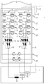
도 1은 제1 회로를 도시한다;
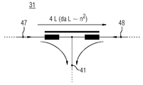
도 2는 상간 인덕터(전류 보상 인덕터)를 도시한다;
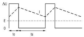
도 3은 리플 전류를 도시한다;
도 4는 잠수함을 도시한다;
도 5는 제2 회로를 도시한다.
Claims (11)
- 제1 상 접속부(phase connection)(21)를 갖는 제1 하프 브리지(half-bridge)(11), 제2 상 접속부(22)를 갖는 제2 하프 브리지(12), 제3 상 접속부(23)를 갖는 제3 하프 브리지(13) 및 제4 상 접속부(24)를 갖는 제4 하프 브리지(14)를 가지는 구동 장치(1)로서, 제1 상 접속부(21)는 제1 모터 권선 측 접속부(41)를 갖는 제1 전류 보상 인덕터(current-compensated inductor)(31)를 통해 제2 상 접속부(22)와 연결되고, 제3 상 접속부(23)는 제2 모터 권선 측 접속부(42)를 갖는 제2 전류 보상 인덕터(32)를 통해 제4 상 접속부(24)와 연결되는, 구동 장치(1).
- 제1항에 있어서, 상기 구동 장치는 제1 모터 권선(50)을 가지며, 제1 모터 권선(50)은 제1 모터 권선 단부(51)를 갖고 제2 모터 권선 단부(52)를 갖고, 제1 모터 권선 측 접속부(41)는 제1 모터 권선 단부(51)와 연결되고, 제2 모터 권선 측 접속부(42)는 제2 모터 권선 단부(52)와 연결되는, 구동 장치(1).
- 제1항에 있어서, 상기 구동 장치는 제5 상 접속부(25)를 갖는 제5 하프 브리지(15), 제6 상 접속부(26)를 갖는 제6 하프 브리지(16), 제7 상 접속부(27)를 갖는 제7 하프 브리지(17) 및 제8 상 접속부(28)를 갖는 제8 하프 브리지(18)를 가지며, 제5 상 접속부(25)는 제3 모터 권선 측 접속부(43)를 갖는 제3 전류 보상 인덕터(33)를 통해 제6 상 접속부(26)와 연결되고, 제7 상 접속부(27)는 제4 모터 권선 측 접속부(44)를 갖는 제4 전류 보상 인덕터(34)를 통해 제8 상 접속부(28)와 연결되는, 구동 장치(1).
- 제3항에 있어서, 제5 전류 보상 인덕터(35)가 제5 모터 권선 측 접속부(45)를 가지며, 제6 전류 보상 인덕터(36)가 제6 모터 권선 측 접속부(46)를 갖고, 제1 모터 권선 측 접속부(41) 및 제3 모터 권선 측 접속부(43)는 전력 컨버터 측에서 제5 전류 보상 인덕터(35)와 연결되며, 제2 모터 권선 측 접속부(42) 및 제4 모터 권선 측 접속부(44)는 전력 컨버터 측에서 제6 전류 보상 인덕터(36)와 연결되는, 구동 장치(1).
- 제4항에 있어서, 상기 구동 장치는 제1 모터 권선(50)을 가지며, 제1 모터 권선(50)은 제1 모터 권선 단부(51)를 갖고 제2 모터 권선 단부(52)를 가지며, 제5 모터 권선 측 접속부(45)는 제1 모터 권선 단부(51)와 연결되고, 제6 모터 권선 측 접속부(46)는 제2 모터 권선 단부(52)와 연결되는, 구동 장치(1).
- 제1항 내지 제5항 중 어느 한 항에 있어서, 제1 모터 권선(50)의 제1 모터 권선 단부(51)와의 직접 연결을 위한 제8 하프 브리지(81)가 제공되고, 제1 모터 권선(50)의 제2 모터 권선 단부(51)와의 직접 연결을 위한 제9 하프 브리지(82)가 제공되는, 구동 장치(1).
- 제1항 내지 제6항 중 어느 한 항에 있어서, 모터(59)가 복수의 모터 권선들(50, 51, 52)을 가지며, 복수의 모터 권선들(50, 51, 52)은 적어도 하나의 전류 보상 인덕터(31, 32, 33, 34, 35, 36)를 통해 하프 브리지들(11, 12, 13, 14, 15, 16, 17, 18), 특히 H-브리지들(86, 87, 88, 89)과 각각 연결되고, 상기 각각의 모터 권선(50, 51, 52)은 제8 하프 브리지 및 제9 하프 브리지(81, 82)와도 연결되고, 제8 하프 브리지 및 제9 하프 브리지(81, 82)는 특히 인덕터 없이 상기 각각의 모터 권선(50, 51, 52)과 연결되는, 구동 장치(1).
- 제1항 내지 제7항 중 어느 한 항에 있어서, 2개의 하프 브리지들(11, 12)은 인버터 모듈(86)을 형성하는, 구동 장치(1).
- 복수의 인버터 모듈들(60, 61, 62)을 갖는 구동 장치(1)를 작동시키는 방법으로서, 복수의 인버터 모듈들(60, 61, 62)은 각각 복수의 하프 브리지들(11, 12, 13, 14, 15, 16, 17, 18)을 갖고, 하프 브리지들(11, 12, 13, 14, 15, 16, 17, 18)은 반파 내에서 오프셋 방식으로 구동되는, 구동 장치의 작동 방법.
- 제9항에 있어서, 모터 권선들(50, 51, 52)을 갖는 전기 기계(59)의 제1 전력 범위에 대해서는, 전류 보상 인덕터(31, 32, 33, 34, 35, 36)를 통해 전기 기계(59)와 연결되는 하프 브리지들(11, 12, 13, 14, 15, 16, 17, 18)이 활성이고, 상기 제1 전력 범위보다 큰 제2 전력 범위에서는, 인덕터 없이 전기 기계(59)와 연결되는 하프 브리지들(81, 82)이 활성인, 구동 장치의 작동 방법.
- 제9항 또는 제10항에 있어서, 제1항 내지 제8항 중 어느 한 항에 따른 구동 장치가 사용되는, 구동 장치의 작동 방법.
Applications Claiming Priority (3)
| Application Number | Priority Date | Filing Date | Title |
|---|---|---|---|
| DE102017217948.1 | 2017-10-09 | ||
| DE102017217948.1A DE102017217948A1 (de) | 2017-10-09 | 2017-10-09 | Antriebseinrichtung bzw. deren Betrieb |
| PCT/EP2018/076762 WO2019072634A1 (de) | 2017-10-09 | 2018-10-02 | Antriebseinrichtung bzw. deren betrieb |
Publications (2)
| Publication Number | Publication Date |
|---|---|
| KR20200044965A true KR20200044965A (ko) | 2020-04-29 |
| KR102439088B1 KR102439088B1 (ko) | 2022-09-02 |
Family
ID=63840808
Family Applications (1)
| Application Number | Title | Priority Date | Filing Date |
|---|---|---|---|
| KR1020207010162A Active KR102439088B1 (ko) | 2017-10-09 | 2018-10-02 | 구동 장치 및 그 작동 |
Country Status (5)
| Country | Link |
|---|---|
| EP (1) | EP3652852B1 (ko) |
| KR (1) | KR102439088B1 (ko) |
| DE (1) | DE102017217948A1 (ko) |
| ES (1) | ES2975189T3 (ko) |
| WO (1) | WO2019072634A1 (ko) |
Cited By (1)
| Publication number | Priority date | Publication date | Assignee | Title |
|---|---|---|---|---|
| DE202021004397U1 (de) | 2020-04-14 | 2024-02-08 | Lg Energy Solution, Ltd. | Batteriemodul und Batteriepack mit diesem Modul |
Families Citing this family (4)
| Publication number | Priority date | Publication date | Assignee | Title |
|---|---|---|---|---|
| DE102020200872A1 (de) | 2020-01-24 | 2021-07-29 | Schmidhauser Ag | Stromrichter, Ladesäule und Fahrzeug |
| DE102020209302A1 (de) * | 2020-07-23 | 2022-01-27 | Siemens Energy Global GmbH & Co. KG | Betreiben einer Antriebseinrichtung |
| EP4092895A1 (de) | 2021-05-18 | 2022-11-23 | Siemens Energy Global GmbH & Co. KG | Verfahren zum betrieb eines gleichstromstellers zur versorgung einer elektrolyseeinrichtung mit elektrischer betriebsenergie |
| CN114248898B (zh) * | 2021-12-27 | 2024-11-05 | 中国船舶重工集团公司第七0五研究所 | 一种双余度推进装置和水下航行器 |
Citations (1)
| Publication number | Priority date | Publication date | Assignee | Title |
|---|---|---|---|---|
| KR20140119164A (ko) * | 2012-01-30 | 2014-10-08 | 지멘스 악티엔게젤샤프트 | 교류 모터 또는 직류 모터의 선택적 제어 |
Family Cites Families (5)
| Publication number | Priority date | Publication date | Assignee | Title |
|---|---|---|---|---|
| DE3433886A1 (de) | 1984-09-14 | 1986-03-27 | Siemens AG, 1000 Berlin und 8000 München | Steuereinrichtung fuer einen gleichstrom-halbleitersteller |
| US6545450B1 (en) * | 1999-07-02 | 2003-04-08 | Advanced Energy Industries, Inc. | Multiple power converter system using combining transformers |
| US7109681B2 (en) * | 2004-08-25 | 2006-09-19 | Hamilton Sundstrand Corporation | Parallel inverter motor drive with improved waveform and reduced filter requirements |
| DE102011007599A1 (de) | 2011-04-18 | 2012-10-18 | Siemens Aktiengesellschaft | Verfahren zum Betrieb eines Unterseebootes sowie Unterseeboot |
| DE102013220502B4 (de) * | 2013-10-11 | 2015-07-30 | Bayerische Motoren Werke Aktiengesellschaft | Skalierbares elektrisches Antriebssystem |
-
2017
- 2017-10-09 DE DE102017217948.1A patent/DE102017217948A1/de active Pending
-
2018
- 2018-10-02 EP EP18785883.2A patent/EP3652852B1/de active Active
- 2018-10-02 ES ES18785883T patent/ES2975189T3/es active Active
- 2018-10-02 WO PCT/EP2018/076762 patent/WO2019072634A1/de not_active Ceased
- 2018-10-02 KR KR1020207010162A patent/KR102439088B1/ko active Active
Patent Citations (1)
| Publication number | Priority date | Publication date | Assignee | Title |
|---|---|---|---|---|
| KR20140119164A (ko) * | 2012-01-30 | 2014-10-08 | 지멘스 악티엔게젤샤프트 | 교류 모터 또는 직류 모터의 선택적 제어 |
Cited By (1)
| Publication number | Priority date | Publication date | Assignee | Title |
|---|---|---|---|---|
| DE202021004397U1 (de) | 2020-04-14 | 2024-02-08 | Lg Energy Solution, Ltd. | Batteriemodul und Batteriepack mit diesem Modul |
Also Published As
| Publication number | Publication date |
|---|---|
| ES2975189T3 (es) | 2024-07-03 |
| WO2019072634A1 (de) | 2019-04-18 |
| EP3652852B1 (de) | 2024-01-10 |
| KR102439088B1 (ko) | 2022-09-02 |
| EP3652852A1 (de) | 2020-05-20 |
| DE102017217948A1 (de) | 2019-04-11 |
Similar Documents
| Publication | Publication Date | Title |
|---|---|---|
| KR102868246B1 (ko) | 다중 출력을 가진 멀티브리지 전력 컨버터 | |
| KR102439088B1 (ko) | 구동 장치 및 그 작동 | |
| US9379597B2 (en) | System for driving electromagnetic appliance and motor driven vehicle | |
| US7446435B2 (en) | Power converter system and method | |
| JP4727882B2 (ja) | 電気エネルギーを変換するためのコンバータ | |
| KR102719185B1 (ko) | Xram 전류 증배기가 있는 에너지 저장 모듈 | |
| US20140239876A1 (en) | Electric drive with reconfigurable winding | |
| Nallamekala et al. | A fault-tolerant dual three-level inverter configuration for multipole induction motor drive with reduced torque ripple | |
| US8072190B2 (en) | Permanent magnet generator control | |
| EP2290802A1 (en) | Regenerative switched reluctance motor driving system | |
| US12451830B2 (en) | Arrangement for electric power conversion and dual electric drive | |
| Singh et al. | Energy saving strategy on electric propulsion system integrated with doubly fed asynchronous motors | |
| Cheng et al. | Integrated drive converter of SDS-SRM with isolation and nonisolation charging capabilities for electric vehicle | |
| RU2529306C1 (ru) | Электромеханическая трансмиссия | |
| KR101654755B1 (ko) | 교류 모터 또는 직류 모터의 선택적 제어 | |
| CN108054965B (zh) | 自强化励磁退磁隔离解耦简易开关磁阻发电机功率变换器 | |
| Reddy et al. | Performance enhancement of PPMIM drives by using three 3-Phase four-leg inverters | |
| KR102194406B1 (ko) | 충전 어셈블리 | |
| Wang et al. | Space vector modulation based on lookup table for a dual-inverter-fed open-end winding PMSM drive | |
| Tajima et al. | Experimental studies on drive performances of wound field synchronous motor drive integrated with ZSI | |
| JPH09182394A (ja) | 交流電動機給電システム | |
| EP2602926A1 (en) | An electronic power converter | |
| JP4161253B2 (ja) | 多相交流電圧調整装置 | |
| JPH09275698A (ja) | スイッチド・リラクタンスモータの駆動回路およびその制御方法 | |
| US20250317083A1 (en) | Reconfigurable synchronous machine |
Legal Events
| Date | Code | Title | Description |
|---|---|---|---|
| A201 | Request for examination | ||
| PA0105 | International application |
Patent event date: 20200408 Patent event code: PA01051R01D Comment text: International Patent Application |
|
| PA0201 | Request for examination | ||
| PG1501 | Laying open of application | ||
| E902 | Notification of reason for refusal | ||
| PE0902 | Notice of grounds for rejection |
Comment text: Notification of reason for refusal Patent event date: 20211105 Patent event code: PE09021S01D |
|
| N231 | Notification of change of applicant | ||
| PN2301 | Change of applicant |
Patent event date: 20220225 Comment text: Notification of Change of Applicant Patent event code: PN23011R01D |
|
| E701 | Decision to grant or registration of patent right | ||
| PE0701 | Decision of registration |
Patent event code: PE07011S01D Comment text: Decision to Grant Registration Patent event date: 20220530 |
|
| GRNT | Written decision to grant | ||
| PR0701 | Registration of establishment |
Comment text: Registration of Establishment Patent event date: 20220829 Patent event code: PR07011E01D |
|
| PR1002 | Payment of registration fee |
Payment date: 20220830 End annual number: 3 Start annual number: 1 |
|
| PG1601 | Publication of registration |