KR20200051602A - Workpiece spindle for magnetic shoe external cylindrical grinder, and magnetic shoe external cylindrical grinder - Google Patents
Workpiece spindle for magnetic shoe external cylindrical grinder, and magnetic shoe external cylindrical grinder Download PDFInfo
- Publication number
- KR20200051602A KR20200051602A KR1020207006104A KR20207006104A KR20200051602A KR 20200051602 A KR20200051602 A KR 20200051602A KR 1020207006104 A KR1020207006104 A KR 1020207006104A KR 20207006104 A KR20207006104 A KR 20207006104A KR 20200051602 A KR20200051602 A KR 20200051602A
- Authority
- KR
- South Korea
- Prior art keywords
- workpiece
- spindle
- gripping device
- grinding
- gripping
- Prior art date
- Legal status (The legal status is an assumption and is not a legal conclusion. Google has not performed a legal analysis and makes no representation as to the accuracy of the status listed.)
- Abandoned
Links
Images


Classifications
-
- B—PERFORMING OPERATIONS; TRANSPORTING
- B24—GRINDING; POLISHING
- B24B—MACHINES, DEVICES, OR PROCESSES FOR GRINDING OR POLISHING; DRESSING OR CONDITIONING OF ABRADING SURFACES; FEEDING OF GRINDING, POLISHING, OR LAPPING AGENTS
- B24B5/00—Machines or devices designed for grinding surfaces of revolution on work, including those which also grind adjacent plane surfaces; Accessories therefor
- B24B5/01—Machines or devices designed for grinding surfaces of revolution on work, including those which also grind adjacent plane surfaces; Accessories therefor for combined grinding of surfaces of revolution and of adjacent plane surfaces on work
-
- B—PERFORMING OPERATIONS; TRANSPORTING
- B24—GRINDING; POLISHING
- B24B—MACHINES, DEVICES, OR PROCESSES FOR GRINDING OR POLISHING; DRESSING OR CONDITIONING OF ABRADING SURFACES; FEEDING OF GRINDING, POLISHING, OR LAPPING AGENTS
- B24B41/00—Component parts such as frames, beds, carriages, headstocks
- B24B41/04—Headstocks; Working-spindles; Features relating thereto
- B24B41/044—Grinding spindles with magnetic or electromagnetic bearings; Features related thereto
-
- B—PERFORMING OPERATIONS; TRANSPORTING
- B24—GRINDING; POLISHING
- B24B—MACHINES, DEVICES, OR PROCESSES FOR GRINDING OR POLISHING; DRESSING OR CONDITIONING OF ABRADING SURFACES; FEEDING OF GRINDING, POLISHING, OR LAPPING AGENTS
- B24B41/00—Component parts such as frames, beds, carriages, headstocks
- B24B41/005—Feeding or manipulating devices specially adapted to grinding machines
-
- B—PERFORMING OPERATIONS; TRANSPORTING
- B24—GRINDING; POLISHING
- B24B—MACHINES, DEVICES, OR PROCESSES FOR GRINDING OR POLISHING; DRESSING OR CONDITIONING OF ABRADING SURFACES; FEEDING OF GRINDING, POLISHING, OR LAPPING AGENTS
- B24B41/00—Component parts such as frames, beds, carriages, headstocks
- B24B41/06—Work supports, e.g. adjustable steadies
- B24B41/061—Work supports, e.g. adjustable steadies axially supporting turning workpieces, e.g. magnetically, pneumatically
-
- B—PERFORMING OPERATIONS; TRANSPORTING
- B24—GRINDING; POLISHING
- B24B—MACHINES, DEVICES, OR PROCESSES FOR GRINDING OR POLISHING; DRESSING OR CONDITIONING OF ABRADING SURFACES; FEEDING OF GRINDING, POLISHING, OR LAPPING AGENTS
- B24B41/00—Component parts such as frames, beds, carriages, headstocks
- B24B41/06—Work supports, e.g. adjustable steadies
- B24B41/067—Work supports, e.g. adjustable steadies radially supporting workpieces
-
- B—PERFORMING OPERATIONS; TRANSPORTING
- B24—GRINDING; POLISHING
- B24B—MACHINES, DEVICES, OR PROCESSES FOR GRINDING OR POLISHING; DRESSING OR CONDITIONING OF ABRADING SURFACES; FEEDING OF GRINDING, POLISHING, OR LAPPING AGENTS
- B24B5/00—Machines or devices designed for grinding surfaces of revolution on work, including those which also grind adjacent plane surfaces; Accessories therefor
- B24B5/02—Machines or devices designed for grinding surfaces of revolution on work, including those which also grind adjacent plane surfaces; Accessories therefor involving centres or chucks for holding work
- B24B5/04—Machines or devices designed for grinding surfaces of revolution on work, including those which also grind adjacent plane surfaces; Accessories therefor involving centres or chucks for holding work for grinding cylindrical surfaces externally
-
- B—PERFORMING OPERATIONS; TRANSPORTING
- B24—GRINDING; POLISHING
- B24B—MACHINES, DEVICES, OR PROCESSES FOR GRINDING OR POLISHING; DRESSING OR CONDITIONING OF ABRADING SURFACES; FEEDING OF GRINDING, POLISHING, OR LAPPING AGENTS
- B24B5/00—Machines or devices designed for grinding surfaces of revolution on work, including those which also grind adjacent plane surfaces; Accessories therefor
- B24B5/02—Machines or devices designed for grinding surfaces of revolution on work, including those which also grind adjacent plane surfaces; Accessories therefor involving centres or chucks for holding work
- B24B5/06—Machines or devices designed for grinding surfaces of revolution on work, including those which also grind adjacent plane surfaces; Accessories therefor involving centres or chucks for holding work for grinding cylindrical surfaces internally
-
- B—PERFORMING OPERATIONS; TRANSPORTING
- B24—GRINDING; POLISHING
- B24B—MACHINES, DEVICES, OR PROCESSES FOR GRINDING OR POLISHING; DRESSING OR CONDITIONING OF ABRADING SURFACES; FEEDING OF GRINDING, POLISHING, OR LAPPING AGENTS
- B24B5/00—Machines or devices designed for grinding surfaces of revolution on work, including those which also grind adjacent plane surfaces; Accessories therefor
- B24B5/02—Machines or devices designed for grinding surfaces of revolution on work, including those which also grind adjacent plane surfaces; Accessories therefor involving centres or chucks for holding work
- B24B5/12—Machines or devices designed for grinding surfaces of revolution on work, including those which also grind adjacent plane surfaces; Accessories therefor involving centres or chucks for holding work for grinding cylindrical surfaces both externally and internally with several grinding wheels
-
- B—PERFORMING OPERATIONS; TRANSPORTING
- B24—GRINDING; POLISHING
- B24B—MACHINES, DEVICES, OR PROCESSES FOR GRINDING OR POLISHING; DRESSING OR CONDITIONING OF ABRADING SURFACES; FEEDING OF GRINDING, POLISHING, OR LAPPING AGENTS
- B24B5/00—Machines or devices designed for grinding surfaces of revolution on work, including those which also grind adjacent plane surfaces; Accessories therefor
- B24B5/18—Machines or devices designed for grinding surfaces of revolution on work, including those which also grind adjacent plane surfaces; Accessories therefor involving centreless means for supporting, guiding, floating or rotating work
- B24B5/307—Means for supporting work
-
- B—PERFORMING OPERATIONS; TRANSPORTING
- B24—GRINDING; POLISHING
- B24B—MACHINES, DEVICES, OR PROCESSES FOR GRINDING OR POLISHING; DRESSING OR CONDITIONING OF ABRADING SURFACES; FEEDING OF GRINDING, POLISHING, OR LAPPING AGENTS
- B24B5/00—Machines or devices designed for grinding surfaces of revolution on work, including those which also grind adjacent plane surfaces; Accessories therefor
- B24B5/35—Accessories
- B24B5/355—Feeding means
-
- B—PERFORMING OPERATIONS; TRANSPORTING
- B23—MACHINE TOOLS; METAL-WORKING NOT OTHERWISE PROVIDED FOR
- B23Q—DETAILS, COMPONENTS, OR ACCESSORIES FOR MACHINE TOOLS, e.g. ARRANGEMENTS FOR COPYING OR CONTROLLING; MACHINE TOOLS IN GENERAL CHARACTERISED BY THE CONSTRUCTION OF PARTICULAR DETAILS OR COMPONENTS; COMBINATIONS OR ASSOCIATIONS OF METAL-WORKING MACHINES, NOT DIRECTED TO A PARTICULAR RESULT
- B23Q1/00—Members which are comprised in the general build-up of a form of machine, particularly relatively large fixed members
- B23Q1/25—Movable or adjustable work or tool supports
- B23Q1/44—Movable or adjustable work or tool supports using particular mechanisms
- B23Q1/48—Movable or adjustable work or tool supports using particular mechanisms with sliding pairs and rotating pairs
- B23Q1/4828—Movable or adjustable work or tool supports using particular mechanisms with sliding pairs and rotating pairs a single rotating pair followed parallelly by a single sliding pair
-
- B—PERFORMING OPERATIONS; TRANSPORTING
- B23—MACHINE TOOLS; METAL-WORKING NOT OTHERWISE PROVIDED FOR
- B23Q—DETAILS, COMPONENTS, OR ACCESSORIES FOR MACHINE TOOLS, e.g. ARRANGEMENTS FOR COPYING OR CONTROLLING; MACHINE TOOLS IN GENERAL CHARACTERISED BY THE CONSTRUCTION OF PARTICULAR DETAILS OR COMPONENTS; COMBINATIONS OR ASSOCIATIONS OF METAL-WORKING MACHINES, NOT DIRECTED TO A PARTICULAR RESULT
- B23Q3/00—Devices holding, supporting, or positioning work or tools, of a kind normally removable from the machine
- B23Q3/15—Devices for holding work using magnetic or electric force acting directly on the work
- B23Q3/152—Rotary devices
-
- B—PERFORMING OPERATIONS; TRANSPORTING
- B24—GRINDING; POLISHING
- B24B—MACHINES, DEVICES, OR PROCESSES FOR GRINDING OR POLISHING; DRESSING OR CONDITIONING OF ABRADING SURFACES; FEEDING OF GRINDING, POLISHING, OR LAPPING AGENTS
- B24B19/00—Single-purpose machines or devices for particular grinding operations not covered by any other main group
- B24B19/02—Single-purpose machines or devices for particular grinding operations not covered by any other main group for grinding grooves, e.g. on shafts, in casings, in tubes, homokinetic joint elements
- B24B19/06—Single-purpose machines or devices for particular grinding operations not covered by any other main group for grinding grooves, e.g. on shafts, in casings, in tubes, homokinetic joint elements for grinding races, e.g. roller races
Landscapes
- Engineering & Computer Science (AREA)
- Mechanical Engineering (AREA)
- Constituent Portions Of Griding Lathes, Driving, Sensing And Control (AREA)
- Grinding Of Cylindrical And Plane Surfaces (AREA)
- Finish Polishing, Edge Sharpening, And Grinding By Specific Grinding Devices (AREA)
Abstract
본 발명은 마그네틱 슈 외부 원통 연삭기용 가공물 스핀들(10)에 관한 것으로, 상기 가공물 스핀들은, 가공물(21)을 회전시키기 위한 스핀들(12)과; 가공물(21)을 파지하기 위한 파지 장치(18)로서, 파지 장치(18) 내에 가공물(21)을 클램핑하기 위해 마그네틱 슈(46)로서 형성된 파지 슈를 구비한, 파지 장치(18)와; 스핀들(12)에 대한 파지 장치(18)의 축방향 거리를 변동시키기 위해 스핀들(12) 및 파지 장치(18)와 결합된 유압식 자기 코어 리프팅 장치(28);를 포함한다. 유압식 자기 코어 리프팅 장치(28)의 도움으로 축방향으로 변위 가능한 파지 장치(18)에 의해, 가공물(21)의 자동 공급이 더욱 비용 효율적으로 수행될 수 있고, 가공물(21)의 제조 시 향상된 정확도가 달성될 수 있음으로써, 비용 효율적이고 정확도가 높은 환형 가공물(21)의 연삭이 가능해진다.The present invention relates to a workpiece spindle 10 for a magnetic shoe outer cylindrical grinding machine, the workpiece spindle comprising: a spindle 12 for rotating the workpiece 21; A gripping device 18 for gripping the work piece 21, comprising: a gripping device 18 having a gripping shoe formed as a magnetic shoe 46 for clamping the work piece 21 in the gripping device 18; And a hydraulic magnetic core lifting device 28 coupled with the spindle 12 and the gripping device 18 to vary the axial distance of the gripping device 18 to the spindle 12. By the gripping device 18 which is axially displaceable with the aid of the hydraulic magnetic core lifting device 28, automatic feeding of the work piece 21 can be performed more cost-effectively, and improved accuracy in the manufacture of the work piece 21 By being able to be achieved, it is possible to grind the cost-effective and highly accurate annular workpiece 21.
Description
본 발명은, 연삭 동안 가공물을 고정할 수 있고 회전시킬 수 있는, 마그네틱 슈 외부 원통 연삭기(magnetic-shoe external cylindrical grinding machine)용 가공물 스핀들에 관한 것이다.The present invention relates to a workpiece spindle for a magnetic shoe external cylindrical grinding machine, which is capable of holding and rotating a workpiece during grinding.
가공물의 원통 연삭 시, 가공물은 외측 표면에 접촉되는 죠(jaw) 또는 마그네틱 슈에 의해 고정될 수 있고 스핀들의 도움으로 회전될 수 있는 한편, 회전하는 연삭 휠은 가공물의 외측 표면에 접촉한다.During cylindrical grinding of the workpiece, the workpiece can be secured by a jaw or magnetic shoe that contacts the outer surface and can be rotated with the aid of a spindle, while the rotating grinding wheel contacts the outer surface of the workpiece.
환형 가공물을 좁은 공차로 비용 효율적으로 연삭해야 할 필요성은 꾸준히 존재한다.There is a continuing need to cost-effectively grind annular workpieces with narrow tolerances.
본 발명의 과제는, 환형 가공물의 비용 효율적인 연삭을 높은 정확도로 가능하게 하는 조치를 제시하는 것이다.The object of the present invention is to propose measures to enable cost-effective grinding of annular workpieces with high accuracy.
상기 과제는, 본 발명에 따라 청구항 1의 특징들을 갖는 가공물 스핀들에 의해 해결된다. 본 발명의 바람직한 실시예들은, 각각 개별적으로 또는 조합되어 본 발명의 일 양태를 구현할 수 있는 종속 청구항들 및 이하의 상세한 설명에 명시되어 있다.The above object is solved by a workpiece spindle having the features of claim 1 according to the present invention. Preferred embodiments of the present invention are set forth in the dependent claims and the detailed description below, each of which may individually or in combination implement one aspect of the present invention.
본 발명에 따라, 가공물을 회전시키기 위한 스핀들; 가공물을 파지하기 위한 파지 장치로서, 이 파지 장치 내에 가공물을 클램핑하기 위해 마그네틱 슈로서 형성된 파지 슈(holding shoe)를 구비한 파지 장치; 그리고 스핀들에 대한 파지 장치의 축방향 거리를 변동시키기 위해 스핀들 및 파지 장치와 결합된 유압식 자기 코어 리프팅 장치;를 포함하는, 마그네틱 슈 외부 원통 연삭기용 가공물 스핀들이 제공된다.According to the present invention, a spindle for rotating a workpiece; A gripping device for gripping a work piece, comprising: a gripping device having a holding shoe formed as a magnetic shoe for clamping a work piece in the gripping device; And, to change the axial distance of the gripping device to the spindle, there is provided a workpiece spindle for a magnetic shoe external cylindrical grinding machine, comprising: a hydraulic magnetic core lifting device coupled with the spindle and the gripping device.
유압식 자기 코어 리프팅 장치의 도움으로, 파지 장치는 축방향으로 진출 및 인입될 수 있는 한편, 스핀들은 축방향으로 움직이지 않고 유지될 수 있다. 이는, 예를 들어 연삭될 가공물을 자동화된 방식으로, 예를 들어 스위블 암(swivel arm) 및/또는 로딩 심봉의 도움으로, 축방향으로 스핀들 및 파지 장치의 앞에 위치시키는 것, 그리고 그 다음에 가공물을 자기적으로 고정시키기 위해 유압식 자기 코어 리프팅 장치의 도움으로 파지 장치를 진출시키는 것을 가능하게 한다. 필요한 경우, 파지 장치는 그 후에, 가공물을 집어 올리기 위해, 그리고 가공물을 축방향으로 파지 장치 앞에 위치시킨 공구로부터 멀어지는 방향으로 이동시키기 위해, 약간 인입될 수 있다. 이로 인해, 공구와 가공물 스핀들의 충돌이 방지될 수 있다. 특히, 공구 및/또는 가공물의 원치 않는 충돌을 피하기 위하여, 공구가 일 평면에서 가공물 스핀들의 축방향에 대해 수직으로 이동하고, 축방향으로는 이동할 필요가 없는 상황이 가능하다. 이로 인해, 가공물의 자동화된 공급이 간소화될 수 있고, 더욱 비용 효율적으로 수행될 수 있다.With the aid of a hydraulic magnetic core lifting device, the gripping device can enter and exit in the axial direction, while the spindle can be maintained without moving in the axial direction. It is for example to position the workpiece to be ground in an automated manner, for example with the aid of a swivel arm and / or loading shim, axially in front of the spindle and gripping device, and then the workpiece It is possible to advance the gripping device with the aid of a hydraulic magnetic core lifting device to magnetically fix it. If necessary, the gripping device can then be slightly retracted to pick up the workpiece, and to move the workpiece axially away from the tool placed in front of the gripping device. Due to this, collision between the tool and the workpiece spindle can be prevented. In particular, in order to avoid unwanted collisions of the tool and / or the work piece, a situation is possible in which the tool moves in one plane perpendicular to the axial direction of the work piece spindle and does not need to move in the axial direction. Due to this, the automated supply of the work piece can be simplified and more cost-effectively performed.
또한, 파지 장치가 경사진 접촉면으로써 가공물에 접촉하고, 유압식 자기 코어 리프팅 장치에 의해 달성된 축방향 상대 운동에 의해 가공물이 자동으로 파지 장치 상에 센터링될 수 있다. 이 경우, 파지 장치는 가공물을 파지 장치 앞에 위치시켰던 공구 상에 지지될 수 있고, 이로 인해 가공물을 파지 장치 쪽으로 가압할 수 있다. 이로 인해 센터링 오류가 최소화될 수 있음으로써, 특히 원통 연삭 시 환형 가공물에서 일정한 재료 두께가 달성될 수 있다. 특히, 가공물에서는, 이 가공물이 환형 바디로부터 축방향으로 돌출하는 탭(tab)을 구비하는 것이 허용될 수 있다. 파지 장치의 축방향 변위에 의해, 축방향으로 돌출하는 파지 장치의 핑거들이 탭을 스쳐 지나면서 환형 바디에 접촉할 수 있음으로써, 탭으로부터 멀어지는 방향을 향하는 가공물의 단부면의 평면 연삭 시에는 가공물의 축방향 링 폭과 관련하여 매우 높은 정확도가 달성될 수 있다. 이로 인해, 링 폭의 측정을 위해 탭의 단부면에 제공된 기준점이 회피될 수 있음으로써, 탭의 축방향 길이의 공차는 축방향 링 폭의 정확도에 영향을 미칠 수 없게 된다. 이로써, 제조 정확도가 향상된다. 유압식 자기 코어 리프팅 장치의 도움으로 축방향으로 변위될 수 있는 파지 장치에 의해, 가공물의 자동화된 공급이 더욱 비용 효율적으로 수행될 수 있고, 가공물의 제조 시 향상된 정확도가 달성될 수 있음으로써, 환형 가공물의 비용 효율적이고 정확도가 높은 연삭이 가능해진다.In addition, the gripping device contacts the workpiece with an inclined contact surface, and the workpiece can be automatically centered on the gripping device by the axial relative motion achieved by the hydraulic magnetic core lifting device. In this case, the gripping device can be supported on the tool that placed the workpiece in front of the gripping device, thereby pressing the workpiece towards the gripping device. This allows the centering error to be minimized, so that a certain material thickness can be achieved in annular workpieces, especially when cylindrical grinding. In particular, in a workpiece, it may be acceptable for the workpiece to have a tab projecting axially from the annular body. Due to the axial displacement of the gripping device, the fingers of the gripping device projecting in the axial direction can contact the annular body while passing through the tab, so that the workpiece is flat-ground when the end face of the workpiece faces away from the tab. Very high accuracy with respect to the axial ring width can be achieved. Due to this, the reference point provided on the end face of the tab for the measurement of the ring width can be avoided, so that the tolerance of the axial length of the tab cannot affect the accuracy of the axial ring width. Thereby, manufacturing accuracy is improved. By a gripping device that can be axially displaced with the aid of a hydraulic magnetic core lifting device, an automated supply of the work piece can be performed more cost-effectively, and an improved accuracy in manufacturing the work piece can be achieved, thereby making the annular work piece The cost-effective and high-precision grinding becomes possible.
특히, 파지 장치는, 반경방향 내부로부터 환형 가공물에 접하도록 설계된다. 이로 인해, 파지 장치가 예를 들어 원뿔대의 부분인 경사진 외측 표면에 의해 환형 가공물의 내부 직경에 접촉할 수 있게 된다. 유압식 자기 코어 리프팅 장치에 의해 가능해진 파지 장치의 축방향 오프셋에 의해, 가공물이 파지 장치에 충돌하지 않으면서 축방향으로 파지 장치 앞에 위치될 수 있으며, 파지 장치는 축방향 진출 이후에 환형 가공물 내로 침투할 수 있고, 가공물을 파지 장치 상에 자동으로 센터링할 수 있다. 이 경우, 환형 가공물은 특히 파지 장치의 경사진 외측 표면상에 가압될 수 있다. 환형 가공물이 반경방향 외부로부터 파지되는 것이 아니라, 반경방향 내부로부터 파지되기 때문에, 원칙적으로, 가공물의 가공된 부분을 가공되지 않은 부분으로부터 절단하거나 가공물을 2개의 팁 사이에 수용할 필요 없이, 가공물의 전체 외측 표면을 연삭할 수 있다.In particular, the gripping device is designed to come into contact with the annular workpiece from inside the radial direction. This makes it possible for the gripping device to contact the inner diameter of the annular workpiece by, for example, a slanted outer surface which is part of a truncated cone. By the axial offset of the gripping device made possible by the hydraulic magnetic core lifting device, the workpiece can be positioned in front of the gripping device in the axial direction without colliding with the gripping device, and the gripping device penetrates into the annular workpiece after axial advancement And can automatically center the workpiece on the gripping device. In this case, the annular work piece can be pressed in particular on the inclined outer surface of the gripping device. Since the annular workpiece is not gripped from the radially outer side, but from the radially inner side, in principle, there is no need to cut the machined portion of the workpiece from the unmachined portion or to accommodate the workpiece between the two tips, The entire outer surface can be ground.
바람직한 방식으로, 파지 장치는, 반경방향 외부에서 그리고 스핀들로부터 멀어지는 방향을 향하는 제1 단부면에서 가공물에 자유롭게 접근할 수 있도록 설계된다. 예를 들어, 환형 가공물이 오로지 단 하나의 축방향 측면에서만 파지 장치상에 부착되어 고정됨으로써, 외측 표면 및 제1 단부면에 연삭 휠이 접근할 수 있게 된다. 이는, 이를 위해 가공물을 파지 장치로부터 고정 해제하거나 공작 기계를 교체할 필요 없이, 가공물에서 원통 연삭뿐만 아니라 평면 연삭도 수행할 수 있게 한다. 이로 인해, 추가 공작 기계에 대한 비용이 절약될 수 있다.In a preferred manner, the gripping device is designed to allow free access to the workpiece from the radially external and first end faces facing away from the spindle. For example, the annular workpiece is attached and fixed on the gripping device only on one axial side, so that the grinding wheel can be accessed on the outer surface and the first end surface. This makes it possible to perform cylindrical grinding as well as planar grinding on the workpiece, without the need to dismount the workpiece from the gripping device or replace the machine tool for this purpose. This can save money for additional machine tools.
특히 바람직하게, 파지 장치는, 스핀들 쪽을 향하는, 특히 하강되어 위치된 가공물의 제2 단부면에서의 축방향 정지를 위해, 원주 방향으로 서로에 대해 오프셋된 복수의 축방향 정지부를 구비한다.Particularly preferably, the gripping device is provided with a plurality of axial stops offset relative to each other in the circumferential direction for axial stops at the second end face of the workpiece positioned towards the spindle, in particular lowered.
이들 축방향 정지부는 특히, 축방향으로 돌출하는 핑거의, 가공물 쪽을 향하는 단부면에 각각 제공될 수 있다. 가공물의 환형 바디로부터 축방향으로 돌출하는 탭이 핑거들 사이에 형성된 중간 공간 내로 잠길 수 있음으로써, 탭들 사이에 있는 축방향 정지부가 단부면에서 가공물의 환형 바디에 충돌할 수 있다. 가공물의 노출된 제1 단부면의 평면 연삭 시, 스핀들 쪽을 향하는, 탭들 사이의 제2 단부면이 가공물의 링 폭의 축방향 연장을 위한 기준점으로 사용될 수 있음으로써, 높은 공차 요건에서도 높은 정확도로 원하는 링 폭이 달성될 수 있다.These axial stops may each be provided on the end faces facing the workpiece, in particular of the fingers projecting in the axial direction. The tabs projecting axially from the annular body of the workpiece can be locked into an intermediate space formed between the fingers, so that the axial stop between the tabs can collide with the annular body of the workpiece at the end face. In the plane grinding of the exposed first end face of the workpiece, the second end face between the tabs facing the spindle can be used as a reference point for the axial extension of the ring width of the workpiece, with high accuracy even at high tolerance requirements. The desired ring width can be achieved.
특히, 파지 장치는, 가공물을 자기적으로(magnetically) 고정하기 위한 자기 장치를 구비한다. 이로 인해, 파지 장치에 의한 가공물의 마찰 결합식 웨징(wedging) 및/또는 압착이 회피될 수 있거나 감소될 수 있다. 그 대신, 가공물은 전적으로 또는 적어도 부분적으로 파지 장치에 의해 자기적으로 고정될 수 있다. 바람직하게는, 자기 장치가 전자석을 구비함으로써, 가공물을 고정하기 위해 제공될 수 있는 자기력이 가공물의 삽입 및/또는 가공물의 제거를 위해서는 차단될 수 있다. 이로 인해, 가공물의 공급 및 배출 시, 가공물의 자동 핸들링이 간소화될 수 있고, 그와 동시에 특히 강자성으로 구현된 가공물이 파지 장치 내에 잘 파지되는 상태가 달성될 수 있다.In particular, the gripping device is provided with a magnetic device for magnetically fixing the workpiece. Due to this, friction-coupled wedging and / or compression of the workpiece by the gripping device can be avoided or reduced. Instead, the work piece can be held entirely or at least partially magnetically by a gripping device. Preferably, by providing the electromagnet with a magnetic device, the magnetic force that can be provided for fixing the workpiece can be blocked for insertion of the workpiece and / or removal of the workpiece. Due to this, when supplying and discharging the work piece, the automatic handling of the work piece can be simplified, and at the same time, a state in which the work piece embodied in particular with ferromagnetic properties is well held in the gripping device can be achieved.
바람직한 방식으로, 파지 장치는 가공물을 수용하기 위한 교체 가능 어댑터를 구비하며, 이 어댑터는 특히 상이하게 성형된 하나 이상의 가공물을 수용하도록 설계된다. 어댑터가 용이하게 교체될 수 있음으로써, 가공물 스핀들은 제조될 다른 가공물에 용이하게 비용 효율적으로 매칭될 수 있다. 또한, 어댑터는, 한 가지 이상의 가공물을 수용할 수 있기 위하여, 상이한 가공물에 매칭되는 기능 면들을 가질 수 있다. 이로써, 예를 들어 내부 직경이 더 작은 가공물을 위한 외측 표면이, 내부 직경이 더 큰 가공물을 위한 외측 표면보다 축방향으로 더 강하게 돌출할 수 있다. 유압식 자기 코어 리프팅 장치에 의해 다양한 외측 표면의 축방향 오프셋이 보상될 수 있음으로써, 2개의 가공물이 스핀들에 대해 동일한 축방향 거리를 두고 배치될 수 있다. 이로써, 가공물을 공급 및/또는 배출하기 위한 자동화된 공급 장치가 재사용될 수 있고, 이로 인해 비용이 절약될 수 있다.In a preferred manner, the gripping device is provided with a replaceable adapter for accommodating the workpiece, which adapter is specifically designed to accommodate one or more differently shaped workpieces. By allowing the adapter to be easily replaced, the workpiece spindle can be easily and cost-effectively matched to other workpieces to be manufactured. In addition, the adapter can have functional faces that match different workpieces to accommodate more than one workpiece. Thereby, for example, the outer surface for a workpiece with a smaller inner diameter can protrude more strongly in the axial direction than the outer surface for a workpiece with a larger inner diameter. The axial offset of the various outer surfaces can be compensated by the hydraulic magnetic core lifting device, so that the two workpieces can be arranged at the same axial distance to the spindle. Thereby, the automated feeding device for feeding and / or discharging the work piece can be reused, thereby saving costs.
본 발명에 따르면, 파지 장치는, 파지 장치 내에 가공물을 클램핑하기 위해 마그네틱 슈로서 형성된 파지 슈를 구비한다. 이 경우, 파지 슈는, 파지 장치가 가공물의 수용을 위해 진출 가능해지기 전에 가공물이 배치될 수 있는 트레이(tray)를 형성할 수 있다. 파지 슈는 바람직하게 가공물을 위한 축방향 정지부를 형성할 수 있으며, 그리고/또는 파지 장치의 진출 시 가공물을 축방향으로 밀어내지 않도록 하기 위해 가공물 상에 충분한 고정력을 가할 수 있다.According to the present invention, the gripping device includes a gripping shoe formed as a magnetic shoe for clamping a work piece in the gripping device. In this case, the gripping shoe can form a tray through which the workpiece can be placed before the gripping device becomes advancing for acceptance of the workpiece. The gripping shoe can preferably form an axial stop for the workpiece, and / or a sufficient fixing force can be applied on the workpiece to prevent the workpiece from being pushed axially upon entry of the gripping device.
특히, 스핀들을 고정하기 위한 잠금 장치가 제공된다. 원통 연삭 시에는 스핀들의 잠금이 해제될 수 있음으로써, 가공물뿐만 아니라 연삭 휠도 회전할 수 있다. 가공물의 단부면을 평면 연삭하는 경우에는, 연삭 휠만 회전하고 스핀들은 잠금 장치에 의해 고정되는 것으로 충분할 수 있다. 이로 인해, 평면 연삭 시 높은 정확도를 가능하게 하는 정의된 상대 운동이 구현된다.In particular, a locking device for fixing the spindle is provided. The spindle can be unlocked during cylindrical grinding, so that the grinding wheel as well as the workpiece can rotate. In the case of plane grinding of the end face of the workpiece, it may be sufficient to rotate only the grinding wheel and the spindle to be fixed by a locking device. This results in a defined relative motion that enables high accuracy in plane grinding.
본 발명은 또한, 연삭 동안 가공물을 파지하기 위한 본 발명에 따른 가공물 스핀들을 구비한, 환형 가공물의 원통 연삭 및 평면 연삭을 위한 마그네틱 슈 외부 원통 연삭기와도 관련이 있으며, 상기 연삭기에는 가공물의 반경방향 외측 표면의 원통 연삭을 위한 제1 연삭 휠 및 가공물의 제1 단부면의 평면 연삭을 위한 제2 연삭 휠, 또는 가공물의 반경방향 외측 표면의 원통 연삭과 가공물의 제1 단부면의 평면 연삭 모두를 위한 하나의 연삭 휠이 제공된다. 원통 연삭 및 평면 연삭을 위해, 다양한 연삭 휠 또는 하나의 공통 연삭 휠이 사용될 수 있다. 리프팅 장치의 도움으로 축방향으로 변위될 수 있는 파지 장치에 의해서는, 가공물의 자동화된 공급이 더욱 비용 효율적으로 수행될 수 있고, 가공물의 제조 시 향상된 정확도가 달성될 수 있음으로써, 환형 가공물의 비용 효율적인 연삭이 높은 정확도로 가능해진다.The present invention also relates to a cylindrical shoe external cylindrical grinding machine for cylindrical grinding and planar grinding of an annular workpiece having a workpiece spindle according to the invention for gripping the workpiece during grinding, wherein the grinding machine has a radial direction of the workpiece The first grinding wheel for cylindrical grinding of the outer surface and the second grinding wheel for flat grinding of the first end face of the workpiece, or both the cylindrical grinding of the radially outer surface of the workpiece and the plane grinding of the first end face of the workpiece. One grinding wheel is provided. For cylindrical grinding and planar grinding, various grinding wheels or one common grinding wheel can be used. By means of a gripping device that can be axially displaced with the aid of a lifting device, the automated supply of the work piece can be performed more cost-effectively, and the improved accuracy in manufacturing the work piece can be achieved, thereby reducing the cost of the annular work piece. Efficient grinding becomes possible with high accuracy.
바람직하게는, 복수의 개별 분리된 가공물을 파지 장치 내로 공급하기 위한 공급 아암이 제공되며, 이 공급 아암은 가공물을 변위시키기 위해 이동 가능한 로딩 심봉(loading mandrel)을 구비하고, 상기 로딩 심봉은 축방향으로 스핀들 앞에 그리고/또는 파지 장치 앞에 위치할 수 있다. 공급 아암 내에는, 개별 분리 장치의 도움으로 분리될 수 있는 연삭될 복수의 가공물이 삽입되어 있을 수 있다. 각각의 가공물은 로딩 심봉에 의해 집어 올려져서, 특히 공구 스핀들의 축방향에 대해 수직으로 연장되는 평면 내부에서 파지 장치 앞에 위치될 수 있다. 이를 위해, 로딩 심봉은 예를 들어 선형 가이드를 따라 안내될 수 있으며, 그리고/또는 피벗 포인트를 중심으로 원형 트랙 상에서 가공물과 함께 움직일 수 있다. 연삭 후에는, 로딩 심봉이 가공물을 재차 집어 올려서 역으로 공급 아암 내로 이동시킬 수 있으며, 이곳에서 가공물이 로딩 심봉로부터 멀어지는 방향으로 방출될 수 있다. 그 다음에, 또 다른 개별 분리된 가공물이 로딩 심봉에 의해 가공물 스핀들의 파지 장치 앞에 위치될 수 있다. 이 경우, 가공물의 공급 및 방출은 자동화된 방식으로 수행될 수 있다.Preferably, a supply arm for supplying a plurality of individually separated workpieces into a gripping device is provided, the supply arm having a movable loading mandrel to displace the workpiece, the loading core being axial Can be located in front of the spindle and / or in front of the gripping device. In the supply arm, a plurality of workpieces to be ground can be inserted, which can be separated with the aid of separate separation devices. Each work piece can be picked up by a loading shim and placed in front of the gripping device, especially in a plane extending perpendicular to the axial direction of the tool spindle. To this end, the loading shim can be guided, for example along a linear guide, and / or can be moved with the workpiece on a circular track around the pivot point. After grinding, the loading shim can pick up the workpiece again and move it back into the feeding arm, where the workpiece can be released in a direction away from the loading shim. Then, another individually separated workpiece can be placed in front of the gripping device of the workpiece spindle by a loading shim. In this case, the supply and release of the workpiece can be carried out in an automated manner.
이하에서는 바람직한 실시예들에 기초한 첨부 도면들을 참조하여 예시적으로 본 발명이 설명되며, 후속하여 설명되는 특징들은 각각 개별적으로도 또는 조합된 형태로도 본 발명의 일 양태를 나타낼 수 있다.Hereinafter, the present invention will be exemplarily described with reference to the accompanying drawings based on preferred embodiments, and features described subsequently may represent one aspect of the present invention individually or in combination.
도 1은 마그네틱 슈 외부 원통 연삭기용 가공물 스핀들의 개략적 단면도이다.
도 2는 도 1에 도시된 가공물 스핀들용 어댑터의 개략적 사시도이다.
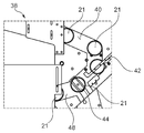
도 3은 도 1에 도시된 가공물 스핀들에 환형 가공물을 공급하기 위한 공급 아암의 개략적 후면도이다.
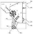
도 4는 도 3에 도시된 공급 아암의 개략적 정면도이다.1 is a schematic cross-sectional view of a workpiece spindle for a magnetic shoe outer cylindrical grinding machine.
FIG. 2 is a schematic perspective view of the adapter for the workpiece spindle shown in FIG. 1;
FIG. 3 is a schematic rear view of a supply arm for supplying an annular workpiece to the workpiece spindle shown in FIG. 1;
4 is a schematic front view of the supply arm shown in FIG. 3.
도 1에 도시된 마그네틱 슈 외부 원통 연삭기용 가공물 스핀들(10)은, 예를 들어 모터에 의해 구동되는 벨트 구동 수단의 도움으로 벨트 풀리(14)를 통해 회전 운동으로 전환될 수 있는 스핀들(12)을 구비한다. 인코더(16)의 도움으로, 스핀들(12)의 각도 위치가 측정될 수 있다. 가공물 스핀들(10)은, 교환 가능한 어댑터(20)를 통해 연삭 공정을 위한 환형 가공물(21)을 고정할 수 있는 파지 장치(18)를 구비한다. 이를 위해, 마그네틱 슈(46)(도 4 참조)와 상호작용하는 자기 장치(22)가 제공되며, 이 경우 철심(26)을 가진, 스위칭 가능한 전기 접속 코일(24)이 전자석을 형성한다. 파지 장치(18)는, 유압식으로 작동 가능한 자기 코어 리프팅 장치(28)를 통해 스핀들(12)에 대해 축방향으로 상대 운동이 가능하도록 설계된다. 이를 위해, 유압식 자기 코어 리프팅 장치(28)는 스핀들(12) 내에서 축방향으로 안내되는 피스톤(30)을 구비할 수 있으며, 이 피스톤은 예를 들어 철심(26)을 통해 파지 장치(18)와 연결되어 있다.The
환형 가공물(21)을 삽입하기 위해, 유압식 자기 코어 리프팅 장치(30)가 파지 장치(18)를 인입시킬 수 있고, 그에 따라 가공물(21)이 축방향으로 파지 장치(18) 앞에 위치될 수 있다. 그런 다음, 파지 장치(18)가 진출하여 어댑터(20)를 이용해 가공물(21)을 집어 올릴 수 있다. 이를 위해, 도 2에 도시된 어댑터(20)는, 환형 가공물(21)을 반경방향 내부로부터 센터링할수 있는, 원추형으로 경사진 외측 표면(32)을 가질 수 있다. 특히, 어댑터(20)는 축방향으로 연장되는 리세스들(34)을 가지며, 이들 리세스 내로 가공물(21)의 환형 바디로부터 축방향으로 돌출하는 탭이 돌출할 수 있다. 인코더(16)의 도움으로, 스핀들(12) 및 이 스핀들(12)과 유압식 자기 코어 리프팅 장치(28)를 통해 연결된 파지 장치(18)는, 파지 장치(18) 앞에서 정의된 각도 위치에 배치된 가공물(21)의 돌출 탭이 어댑터(20) 또는 여타의 부품에 충돌하지 않으면서 어댑터(20)의 리세스(34) 내로 삽입될 수 있는 각도 위치로 회전될 수 있다. 어댑터(20)는 또한, 예를 들어 가공물(21)의 내경 내로 압입되는 외측 표면의 침투 깊이를 제한하기 위해, 가공물(21)에 충돌할 수 있는 복수의, 예컨대 정확히 3개의 축방향 정지부(36)을 구비한다. 특히, 축방향 정지부(36)가 탭에 충돌하지 않고, 탭이 축방향으로 돌출되어 나온 가공물(21)의 환형 바디의 단부면에 충돌함으로써, 가공물(21)의 환형 바디 상에서의 축방향 정지부(36)의 접촉부가, 스핀들(12)로부터 멀어지는 방향을 향하는 가공물(21)의 단부면의 평면 연삭 시, 가공물(21)의 환형 바디의 축방향 링 폭을 높은 정확도로 간단하게 제조할 수 있기 위한 기준점으로서 사용될 수 있다.To insert the
환형 가공물(21)을 공급하기 위하여, 도 3 및 도 4에 도시된 공급 아암(38)이 제공될 수 있으며, 이 경우 환형 가공물(21)은 유입 활송부(inflow chute,40) 내에 보유될 수 있다. 가공물 푸셔(pusher, 42)의 도움으로 가공물(21)은 개별 분리되어, 각각 로딩 심봉(44)에 공급될 수 있다. 로딩 심봉(44)은 환형 가공물(21)을 수용할 수 있고, 예를 들어 이격된 회전축을 중심으로 하는 피벗 운동에 의해 가공물 스핀들(10) 앞에 환형 가공물(21)을 위치시킬 수 있다. 예를 들어, 가공물(21)이 마그네틱 슈(46) 상에 올려질 수 있고, 이 경우 바람직하게는 파지 장치(18)의 어댑터(20)가 환형 가공물(21) 내로 삽입될 때 로딩 심봉(44) 및/또는 마그네틱 슈(46)가 축방향 지지부를 형성할 수 있다. 연삭 후에는, 로딩 심봉(44)이 완성된 가공물(21)을 다시 역으로 공급 아암(38) 내로 이송할 수 있고, 이곳에서 가공물(21)이 인출 활송부(outflow chute, 48)를 통해 방출될 수 있다.In order to supply the
10: 가공물 스핀들
12: 스핀들
14: 벨트 풀리
16: 인코더
18: 파지 장치
20: 어댑터
21: 가공물
22: 자기 장치
24: 코일
26: 철심
28: 리프팅 장치
30: 피스톤
32: 외측 표면
34: 리세스
36: 축방향 정지부
38: 공급 아암
40: 유입 활송부
42: 가공물 푸셔
44: 로딩 심봉
46: 마그네틱 슈
48: 인출 활송부10: Workpiece spindle
12: Spindle
14: belt pulley
16: Encoder
18: gripping device
20: adapter
21: workpiece
22: magnetic device
24: coil
26: iron core
28: lifting device
30: piston
32: outer surface
34: recess
36: axial stop
38: supply arm
40: inlet chute
42: workpiece pusher
44: loading rod
46: Magnetic shoe
48: withdrawal chute
Claims (9)
가공물(21)을 회전시키기 위한 스핀들(12)과;
가공물(21)을 파지하기 위한 파지 장치(18)로서, 이 파지 장치(18) 내에 가공물(21)을 클램핑하기 위해 마그네틱 슈(46)로서 형성된 파지 슈를 구비한, 파지 장치(18)와;
스핀들(12)에 대한 파지 장치(18)의 축방향 거리를 변동시키기 위해 스핀들(12) 및 파지 장치(18)와 결합된 유압식 자기 코어 리프팅 장치(28);
를 포함하는, 마그네틱 슈 외부 원통 연삭기용 가공물 스핀들.As a workpiece spindle for the cylindrical shoe external cylindrical grinding machine,
A spindle 12 for rotating the workpiece 21;
A gripping device 18 for gripping the workpiece 21, comprising: a gripping device 18 having a gripping shoe formed as a magnetic shoe 46 for clamping the workpiece 21 in the gripping device 18;
A hydraulic magnetic core lifting device 28 coupled with the spindle 12 and the gripping device 18 to vary the axial distance of the gripping device 18 to the spindle 12;
A workpiece spindle for a cylindrical shoe external cylindrical grinding machine comprising a.
가공물(21)의 반경방향 외측 표면의 원통 연삭을 위한 제1 연삭 휠 및 가공물(21)의 제1 단부면의 평면 연삭을 위한 제2 연삭 휠, 또는 가공물(21)의 반경방향 외측 표면의 원통 연삭과 가공물(21)의 제1 단부면의 평면 연삭 모두를 위한 하나의 연삭 휠이 제공된, 마그네틱 슈 외부 원통 연삭기.Magnetic shoe outer cylinder for cylindrical grinding and planar grinding of annular workpiece 21 with a workpiece spindle 10 for gripping workpiece 21 during grinding according to claim 1. As a grinding machine,
A first grinding wheel for cylindrical grinding of the radially outer surface of the workpiece 21 and a second grinding wheel for flat grinding of the first end face of the workpiece 21, or a cylinder of the radially outer surface of the workpiece 21 A magnetic shoe outer cylindrical grinder provided with one grinding wheel for both grinding and planar grinding of the first end face of the workpiece 21.
Applications Claiming Priority (3)
| Application Number | Priority Date | Filing Date | Title |
|---|---|---|---|
| DE102017120333.8 | 2017-09-05 | ||
| DE102017120333.8A DE102017120333A1 (en) | 2017-09-05 | 2017-09-05 | Workpiece spindle for a grinding machine |
| PCT/DE2018/100728 WO2019047995A1 (en) | 2017-09-05 | 2018-08-22 | WORKPIECE SPINDLE FOR MAGNETIC SHOE EXTERNAL ROUND GRINDING MACHINE AND MAGNETIC SHOE EXTERNAL ROUND GRINDING MACHINE |
Publications (1)
| Publication Number | Publication Date |
|---|---|
| KR20200051602A true KR20200051602A (en) | 2020-05-13 |
Family
ID=63490130
Family Applications (1)
| Application Number | Title | Priority Date | Filing Date |
|---|---|---|---|
| KR1020207006104A Abandoned KR20200051602A (en) | 2017-09-05 | 2018-08-22 | Workpiece spindle for magnetic shoe external cylindrical grinder, and magnetic shoe external cylindrical grinder |
Country Status (7)
| Country | Link |
|---|---|
| US (1) | US20200353589A1 (en) |
| EP (1) | EP3678818A1 (en) |
| JP (1) | JP6945719B2 (en) |
| KR (1) | KR20200051602A (en) |
| CN (1) | CN111051003B (en) |
| DE (1) | DE102017120333A1 (en) |
| WO (1) | WO2019047995A1 (en) |
Families Citing this family (3)
| Publication number | Priority date | Publication date | Assignee | Title |
|---|---|---|---|---|
| CN112548717B (en) * | 2020-12-09 | 2022-04-29 | 富贤勋电子科技(南通)有限公司 | Roughening treatment device for radiating fins of CPU radiator |
| CN116652798B (en) * | 2023-07-25 | 2023-10-31 | 江苏考力特节能风机有限公司 | Internal circle grinding equipment for polishing fan impeller |
| DE102024208379B4 (en) * | 2024-09-04 | 2026-04-23 | Zf Friedrichshafen Ag | Drum assembly for a tire test stand and device for grinding the outer circumferential surface of the drum |
Family Cites Families (20)
| Publication number | Priority date | Publication date | Assignee | Title |
|---|---|---|---|---|
| JPS5822246U (en) * | 1981-07-30 | 1983-02-10 | 日本精工株式会社 | Spindle device with electromagnetic chuck |
| JPH01127203A (en) * | 1986-12-08 | 1989-05-19 | Suga Tekkosho:Kk | Loader in numerically controlled turret lathe |
| CN2149272Y (en) * | 1993-03-02 | 1993-12-15 | 侯来虎 | Full-automatic multifunctional efficient cylindrical grinding machine |
| US5740699A (en) * | 1995-04-06 | 1998-04-21 | Spar Aerospace Limited | Wrist joint which is longitudinally extendible |
| JP3991648B2 (en) * | 2001-10-25 | 2007-10-17 | 日本精工株式会社 | Workpiece holding device |
| DE20218009U1 (en) * | 2002-11-21 | 2003-03-06 | FESTO AG & Co., 73734 Esslingen | Handling and manipulating machine for aligning and gripping workpieces has gripping head at end of long shaft and fluidic linear drive at other end |
| JP2005014189A (en) * | 2003-06-27 | 2005-01-20 | Seiko Instruments Inc | Cylinder grinding method and cylinder grinding attachment |
| JP4621971B2 (en) * | 2004-10-27 | 2011-02-02 | 豊和工業株式会社 | Retractable chuck device and work chucking method |
| CH701156B1 (en) * | 2006-12-28 | 2010-12-15 | Robotic Consulting S A R L | Grinding machine bearing rings. |
| DE102007026841A1 (en) * | 2007-06-06 | 2008-12-11 | Satisloh Ag | Polishing disc for a tool for fine machining of optically effective surfaces on in particular spectacle lenses and method for its production |
| ITBO20080405A1 (en) * | 2008-06-26 | 2009-12-27 | Minganti International Ltd | APPARATUS FOR THE CORRECT CENTERING OF THE MAGNETIC CLAMP AT THE PLATFORM OF THE VERTICAL MANDREL OF A MACHINE TOOL, OF WORKING PARTS OF ROUND SHAPE AND ALSO OF LARGE SIZE AND CONSIDERABLE WEIGHT AND ITS FUNCTIONING METHOD. |
| DE102009047996B3 (en) * | 2009-09-22 | 2011-03-17 | SAV Spann-, Automations-, Normteiletechnik GmbH | Chuck for e.g. clamping, of circularly formed workpiece, has path measuring systems provided for positioning jaws, where actuators, measuring systems and force sensors are connected with control device that is component part of chuck |
| CN101913108B (en) * | 2010-07-27 | 2012-04-18 | 中钢集团邢台机械轧辊有限公司 | Device for flexibly shifting cylindrical grinding machine workpiece |
| DE102011014230A1 (en) * | 2011-03-17 | 2012-09-20 | Satisloh Ag | Device for fine machining of optically effective surfaces on in particular spectacle lenses |
| CN203390678U (en) * | 2013-06-28 | 2014-01-15 | 邢台晶龙电子材料有限公司 | Flat grinding device |
| JP6672682B2 (en) * | 2015-10-05 | 2020-03-25 | 株式会社ジェイテクト | Processing equipment |
| CN205572126U (en) * | 2016-01-25 | 2016-09-14 | 杭州正强万向节有限公司 | Full -automatic grinding of axle sleeve and detection production line |
| CN106239501A (en) * | 2016-09-28 | 2016-12-21 | 洛阳理工学院 | Multiple degrees of freedom hydraulic driving mechanical is used in the carrying of a kind of workshop |
| CN106346322B (en) * | 2016-11-05 | 2019-06-04 | 无锡机床股份有限公司 | The fixture of bearing grinder |
| EP4037158B1 (en) * | 2021-02-02 | 2025-07-30 | Black & Decker, Inc. | Brushless motor including a nested bearing bridge |
-
2017
- 2017-09-05 DE DE102017120333.8A patent/DE102017120333A1/en not_active Withdrawn
-
2018
- 2018-08-22 JP JP2020505472A patent/JP6945719B2/en not_active Expired - Fee Related
- 2018-08-22 EP EP18764995.9A patent/EP3678818A1/en not_active Withdrawn
- 2018-08-22 WO PCT/DE2018/100728 patent/WO2019047995A1/en not_active Ceased
- 2018-08-22 CN CN201880056070.5A patent/CN111051003B/en not_active Expired - Fee Related
- 2018-08-22 KR KR1020207006104A patent/KR20200051602A/en not_active Abandoned
- 2018-08-22 US US16/642,195 patent/US20200353589A1/en not_active Abandoned
Also Published As
| Publication number | Publication date |
|---|---|
| JP2020529331A (en) | 2020-10-08 |
| WO2019047995A1 (en) | 2019-03-14 |
| US20200353589A1 (en) | 2020-11-12 |
| CN111051003A (en) | 2020-04-21 |
| CN111051003B (en) | 2022-04-15 |
| DE102017120333A1 (en) | 2019-03-07 |
| EP3678818A1 (en) | 2020-07-15 |
| JP6945719B2 (en) | 2021-10-06 |
Similar Documents
| Publication | Publication Date | Title |
|---|---|---|
| US9061357B2 (en) | High precision chuck with centering function | |
| US20190099812A1 (en) | Workholding arbor for gears | |
| TWI483806B (en) | Fixture device | |
| KR20200051602A (en) | Workpiece spindle for magnetic shoe external cylindrical grinder, and magnetic shoe external cylindrical grinder | |
| EP0174799B1 (en) | Machine tools, in particular grinding machines with apparatus for changing grinding wheel tools and workpieces | |
| KR101835743B1 (en) | Compound Roller Automatic Apparatus | |
| US20200269368A1 (en) | Tool carrier and tool holder | |
| KR20150004763A (en) | Auto tools change with space allowance for tool rejection of spindle | |
| CN110976933B (en) | A machine tool for mechanical finishing | |
| US20140062039A1 (en) | Quick-change top tooling | |
| KR200472903Y1 (en) | Soft jaw for manufacturing ring | |
| US11904396B2 (en) | Method and apparatus for loading and positioning a workpiece on a gear manufacturing machine | |
| US7422398B2 (en) | Inside machining cutting tool delivery apparatus | |
| JP7067013B2 (en) | Work centering method | |
| US20230302547A1 (en) | Chuck | |
| US12576451B2 (en) | Chuck | |
| US2828588A (en) | Workholder apparatus for axial clamping and radial loading of workpieces | |
| CN202668197U (en) | Turning operation clamp of cylindrical four-way type workpiece | |
| CN102672225A (en) | Mechanical positioning chuck | |
| CN112171502A (en) | Processing device | |
| US20250214151A1 (en) | Universal clamping system, clamping adapter, machine element, processing and/or measuring machine and method of clamping and releasing | |
| US20240269794A1 (en) | Working head for a machine tool having an interchangeable electrospindle | |
| CN108367404B (en) | Machining center and method for machining workpiece blanks in a machining center | |
| JPS5856082Y2 (en) | Workpiece charging/discharging device | |
| JP2025087596A (en) | Method for machining a workpiece and adapter used during machining |
Legal Events
| Date | Code | Title | Description |
|---|---|---|---|
| PA0105 | International application |
St.27 status event code: A-0-1-A10-A15-nap-PA0105 |
|
| PG1501 | Laying open of application |
St.27 status event code: A-1-1-Q10-Q12-nap-PG1501 |
|
| A201 | Request for examination | ||
| P11-X000 | Amendment of application requested |
St.27 status event code: A-2-2-P10-P11-nap-X000 |
|
| P13-X000 | Application amended |
St.27 status event code: A-2-2-P10-P13-nap-X000 |
|
| PA0201 | Request for examination |
St.27 status event code: A-1-2-D10-D11-exm-PA0201 |
|
| E902 | Notification of reason for refusal | ||
| PE0902 | Notice of grounds for rejection |
St.27 status event code: A-1-2-D10-D21-exm-PE0902 |
|
| E13-X000 | Pre-grant limitation requested |
St.27 status event code: A-2-3-E10-E13-lim-X000 |
|
| P11-X000 | Amendment of application requested |
St.27 status event code: A-2-2-P10-P11-nap-X000 |
|
| P13-X000 | Application amended |
St.27 status event code: A-2-2-P10-P13-nap-X000 |
|
| E701 | Decision to grant or registration of patent right | ||
| PE0701 | Decision of registration |
St.27 status event code: A-1-2-D10-D22-exm-PE0701 |
|
| PC1904 | Unpaid initial registration fee |
St.27 status event code: A-2-2-U10-U14-oth-PC1904 St.27 status event code: N-2-6-B10-B12-nap-PC1904 |