KR20200057016A - 분리 가능한 방식으로 결합될 수 있는 액추에이터 유닛과 유체 유닛을 갖는 도징 시스템 - Google Patents
분리 가능한 방식으로 결합될 수 있는 액추에이터 유닛과 유체 유닛을 갖는 도징 시스템 Download PDFInfo
- Publication number
- KR20200057016A KR20200057016A KR1020207010044A KR20207010044A KR20200057016A KR 20200057016 A KR20200057016 A KR 20200057016A KR 1020207010044 A KR1020207010044 A KR 1020207010044A KR 20207010044 A KR20207010044 A KR 20207010044A KR 20200057016 A KR20200057016 A KR 20200057016A
- Authority
- KR
- South Korea
- Prior art keywords
- unit
- actuator
- plug
- fluid
- fluid unit
- Prior art date
- Legal status (The legal status is an assumption and is not a legal conclusion. Google has not performed a legal analysis and makes no representation as to the accuracy of the status listed.)
- Granted
Links
- 239000012530 fluid Substances 0.000 title claims abstract description 194
- 238000010168 coupling process Methods 0.000 claims abstract description 128
- 230000008878 coupling Effects 0.000 claims abstract description 127
- 238000005859 coupling reaction Methods 0.000 claims abstract description 127
- 238000000034 method Methods 0.000 claims abstract description 30
- 238000010438 heat treatment Methods 0.000 claims description 130
- 230000007246 mechanism Effects 0.000 claims description 58
- 239000000463 material Substances 0.000 claims description 24
- 210000002445 nipple Anatomy 0.000 claims description 8
- 210000000515 tooth Anatomy 0.000 description 17
- 238000007789 sealing Methods 0.000 description 14
- 238000007599 discharging Methods 0.000 description 7
- 230000033001 locomotion Effects 0.000 description 5
- 238000004519 manufacturing process Methods 0.000 description 4
- 239000004033 plastic Substances 0.000 description 4
- 230000008569 process Effects 0.000 description 4
- RYGMFSIKBFXOCR-UHFFFAOYSA-N Copper Chemical compound [Cu] RYGMFSIKBFXOCR-UHFFFAOYSA-N 0.000 description 3
- 230000008859 change Effects 0.000 description 3
- 239000004020 conductor Substances 0.000 description 3
- 229910052802 copper Inorganic materials 0.000 description 3
- 239000010949 copper Substances 0.000 description 3
- 238000009826 distribution Methods 0.000 description 3
- 239000004696 Poly ether ether ketone Substances 0.000 description 2
- 229910000831 Steel Inorganic materials 0.000 description 2
- 230000009471 action Effects 0.000 description 2
- 230000008901 benefit Effects 0.000 description 2
- JUPQTSLXMOCDHR-UHFFFAOYSA-N benzene-1,4-diol;bis(4-fluorophenyl)methanone Chemical compound OC1=CC=C(O)C=C1.C1=CC(F)=CC=C1C(=O)C1=CC=C(F)C=C1 JUPQTSLXMOCDHR-UHFFFAOYSA-N 0.000 description 2
- 230000006835 compression Effects 0.000 description 2
- 238000007906 compression Methods 0.000 description 2
- 230000001419 dependent effect Effects 0.000 description 2
- 238000005516 engineering process Methods 0.000 description 2
- 230000005484 gravity Effects 0.000 description 2
- 230000003993 interaction Effects 0.000 description 2
- 239000007788 liquid Substances 0.000 description 2
- 239000002184 metal Substances 0.000 description 2
- 229910052751 metal Inorganic materials 0.000 description 2
- 238000003801 milling Methods 0.000 description 2
- 229920002530 polyetherether ketone Polymers 0.000 description 2
- 238000003825 pressing Methods 0.000 description 2
- 238000000926 separation method Methods 0.000 description 2
- 239000010959 steel Substances 0.000 description 2
- 238000012546 transfer Methods 0.000 description 2
- 239000000853 adhesive Substances 0.000 description 1
- 230000001070 adhesive effect Effects 0.000 description 1
- 230000000712 assembly Effects 0.000 description 1
- 238000000429 assembly Methods 0.000 description 1
- 230000005540 biological transmission Effects 0.000 description 1
- 238000009529 body temperature measurement Methods 0.000 description 1
- 239000002775 capsule Substances 0.000 description 1
- 238000004891 communication Methods 0.000 description 1
- 239000000109 continuous material Substances 0.000 description 1
- 238000005520 cutting process Methods 0.000 description 1
- 238000013500 data storage Methods 0.000 description 1
- 238000013461 design Methods 0.000 description 1
- 238000011010 flushing procedure Methods 0.000 description 1
- 230000006870 function Effects 0.000 description 1
- 239000011810 insulating material Substances 0.000 description 1
- 230000013011 mating Effects 0.000 description 1
- 238000005259 measurement Methods 0.000 description 1
- 230000005226 mechanical processes and functions Effects 0.000 description 1
- 230000000284 resting effect Effects 0.000 description 1
- 229910000679 solder Inorganic materials 0.000 description 1
- 239000000126 substance Substances 0.000 description 1
- 238000012360 testing method Methods 0.000 description 1
- 239000002470 thermal conductor Substances 0.000 description 1
Images


Classifications
-
- G—PHYSICS
- G01—MEASURING; TESTING
- G01F—MEASURING VOLUME, VOLUME FLOW, MASS FLOW OR LIQUID LEVEL; METERING BY VOLUME
- G01F11/00—Apparatus requiring external operation adapted at each repeated and identical operation to measure and separate a predetermined volume of fluid or fluent solid material from a supply or container, without regard to weight, and to deliver it
- G01F11/28—Apparatus requiring external operation adapted at each repeated and identical operation to measure and separate a predetermined volume of fluid or fluent solid material from a supply or container, without regard to weight, and to deliver it with stationary measuring chambers having constant volume during measurement
- G01F11/42—Apparatus requiring external operation adapted at each repeated and identical operation to measure and separate a predetermined volume of fluid or fluent solid material from a supply or container, without regard to weight, and to deliver it with stationary measuring chambers having constant volume during measurement with supply or discharge valves of the rotary or oscillatory type
- G01F11/44—Apparatus requiring external operation adapted at each repeated and identical operation to measure and separate a predetermined volume of fluid or fluent solid material from a supply or container, without regard to weight, and to deliver it with stationary measuring chambers having constant volume during measurement with supply or discharge valves of the rotary or oscillatory type for liquid or semiliquid
-
- B—PERFORMING OPERATIONS; TRANSPORTING
- B05—SPRAYING OR ATOMISING IN GENERAL; APPLYING FLUENT MATERIALS TO SURFACES, IN GENERAL
- B05C—APPARATUS FOR APPLYING FLUENT MATERIALS TO SURFACES, IN GENERAL
- B05C5/00—Apparatus in which liquid or other fluent material is projected, poured or allowed to flow on to the surface of the work
- B05C5/02—Apparatus in which liquid or other fluent material is projected, poured or allowed to flow on to the surface of the work the liquid or other fluent material being discharged through an outlet orifice by pressure, e.g. from an outlet device in contact or almost in contact, with the work
- B05C5/0225—Apparatus in which liquid or other fluent material is projected, poured or allowed to flow on to the surface of the work the liquid or other fluent material being discharged through an outlet orifice by pressure, e.g. from an outlet device in contact or almost in contact, with the work characterised by flow controlling means, e.g. valves, located proximate the outlet
-
- B—PERFORMING OPERATIONS; TRANSPORTING
- B05—SPRAYING OR ATOMISING IN GENERAL; APPLYING FLUENT MATERIALS TO SURFACES, IN GENERAL
- B05C—APPARATUS FOR APPLYING FLUENT MATERIALS TO SURFACES, IN GENERAL
- B05C11/00—Component parts, details or accessories not specifically provided for in groups B05C1/00 - B05C9/00
- B05C11/10—Storage, supply or control of liquid or other fluent material; Recovery of excess liquid or other fluent material
- B05C11/1002—Means for controlling supply, i.e. flow or pressure, of liquid or other fluent material to the applying apparatus, e.g. valves
- B05C11/1034—Means for controlling supply, i.e. flow or pressure, of liquid or other fluent material to the applying apparatus, e.g. valves specially designed for conducting intermittent application of small quantities, e.g. drops, of coating material
-
- G—PHYSICS
- G01—MEASURING; TESTING
- G01F—MEASURING VOLUME, VOLUME FLOW, MASS FLOW OR LIQUID LEVEL; METERING BY VOLUME
- G01F15/00—Details of, or accessories for, apparatus of groups G01F1/00 - G01F13/00 insofar as such details or appliances are not adapted to particular types of such apparatus
- G01F15/18—Supports or connecting means for meters
- G01F15/185—Connecting means, e.g. bypass conduits
-
- Y—GENERAL TAGGING OF NEW TECHNOLOGICAL DEVELOPMENTS; GENERAL TAGGING OF CROSS-SECTIONAL TECHNOLOGIES SPANNING OVER SEVERAL SECTIONS OF THE IPC; TECHNICAL SUBJECTS COVERED BY FORMER USPC CROSS-REFERENCE ART COLLECTIONS [XRACs] AND DIGESTS
- Y02—TECHNOLOGIES OR APPLICATIONS FOR MITIGATION OR ADAPTATION AGAINST CLIMATE CHANGE
- Y02T—CLIMATE CHANGE MITIGATION TECHNOLOGIES RELATED TO TRANSPORTATION
- Y02T10/00—Road transport of goods or passengers
- Y02T10/10—Internal combustion engine [ICE] based vehicles
- Y02T10/12—Improving ICE efficiencies
Landscapes
- Physics & Mathematics (AREA)
- Fluid Mechanics (AREA)
- General Physics & Mathematics (AREA)
- Coating Apparatus (AREA)
- Loading And Unloading Of Fuel Tanks Or Ships (AREA)
- Infusion, Injection, And Reservoir Apparatuses (AREA)
- Exhaust Gas After Treatment (AREA)
Abstract
Description
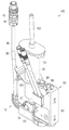
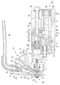
도 1은 유체 유닛이 액추에이터 유닛에 결합된 상태에 있는, 본 발명에 따른 도징 시스템의 일 실시예를 위에서 비스듬히 본 외부 사시도를 도시한다.
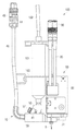
도 2는 도 1의 도징 시스템의 정면도를 도시한다.
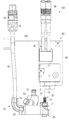
도 3은 유체 유닛이 액추에이터 유닛으로부터 분리된 상태에 있는, 도 1의 도징 시스템의 다른 정면도를 도시한다.
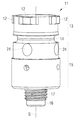
도 4는 도 1 내지 도 3에 따른 도징 시스템의 유체 유닛을 위에서 비스듬히 본 외부 사시도를 도시한다.
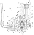
도 5는 도 2에서와 같이 결합된 상태에 있는 유체 유닛과 액추에이터 유닛의 하부 부분을 통한 단면도를 도시한다.
도 6은 도 3에서와 같이 비-결합된 상태에 있는 유체 유닛과 액추에이터 유닛의 하부 부분을 통한 다른 단면도를 도시한다.
도 7은 도 1 내지 도 6에 따른 도징 시스템의 유체 유닛의 플러그 결합부의 측면도를 도시한다.
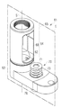
도 8은 도 1 내지 도 6에 따른 도징 시스템의 액추에이터 유닛의 플러그 결합부를 위에서 비스듬히 본 사시도를 도시한다.
도 9는 도 8의 절단면(E)을 따라 플러그 결합부를 통한 단면도를 도시한다.
도 10은 도 9의 절단선(B-B)을 따라 도 7 및 도 8의 플러그 결합부를 통한 단면도를 도시한다.
도 11은 다양한 결합 위치에서 위에서 본 본 발명에 따른 도징 시스템의 예시적인 실시예의 유체 유닛과 액추에이터 유닛의 가능한 결합 상태를 개략적으로 도시한다.
11: (제1) 플러그 결합부
12: 돌출부/톱니부
13: 베이오닛 결합 구획/톱니부 구획/연결 부재
14: 환형 그루브
15: 클램핑 구획
16: 노즐 구획
17: 나사산
18: 노즐 삽입물
19: 밀봉 시트
20: 노즐
21: 노즐 개구/노즐 보어
22: 노즐 챔버
23: 밀봉부/O-링
24: 구형 캐럿
30: 이동 요소/토출 요소/태핏
31: 태핏 팁
32: 태핏 헤드
33: 접촉 표면
34: 스프링
35: 태핏 베어링부
36: 밀봉 지지 링
37: 태핏 밀봉부
40: 가열 장치/가열 모듈
41: 클램핑 나사 구획
42: 가열 블록
43: 노즐 측방 표면 구획
44: 메모리 유닛/EEPROM
45: 리세스
46: 가열 연결 케이블
47: 가열 제어 라인
48: 온도 측정 라인
49: 가열 제어 연결/가열 플러그
50: 저장조 인터페이스
51: 저장조 연결부
52a, 52b: 채널 구획
54: 공급 채널 구획
55: 클램핑 나사
56: 팁
57: 나사 헤드
58: 원추형 니플
59: 프레임부
60: 액추에이터 유닛
61: (제2) 플러그 결합부/대응 플러그 결합부
61Z: 실린더 핀
62: 돌출부/톱니부
63: 베이오닛 결합 구획/장착 구획/장착부
64: 맞물림 구획
65: 고정 구획
66: 리세스
67: 칼라/숄더
68: 관통 구멍
69: 내부 나사산
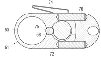
70: 편심 기구
71: 편심 샤프트
72: 편심 구획
73: 스프링
74: 편심 레버
75: 압력 볼
76: 편심 홀더
77: 관통 구멍
78: 구획
79: 액추에이터 스프링
80: 하우징 블록
81: 액추에이터 챔버
82: 작용 챔버
83: 개구
85: 고정 나사
86: 나사 헤드
87: 플러그 결합 연결 구획
88: 나사산 형성된 부분
89: 너트
90: 액추에이터 시스템
91: 액추에이터/압전 요소 스택/압전 스택
91K: 압전 캡슐부
92: 이동 기구
93: 레버
94: 레버 베어링
95: 제어 케이블
96: 액추에이터 시스템 제어 연결부
97: 접촉 표면
98: 가이드 실린더
98Z: 실린더 핀
99: 커버
100: 도징 시스템
101: 저장조/중간 카트리지
102: 저장조 압력 연결부
103: 홀더
K: 선회 축
KP1, KP2, KP3: 결합 위치
E: 토출 방향
S: 플러깅 축
SP1, SP2: 플러그 위치
Claims (16)
- 액추에이터 유닛(60)과, 상기 액추에이터 유닛에 분리 가능한 방식으로 결합될 수 있는 유체 유닛(10)을 포함하는 도징 시스템(100)으로서, 상기 유체 유닛(10)은 노즐(20), 및 이동 가능한 방식으로 장착된 요소(30)를 포함하고, 상기 액추에이터 유닛(60)은 상기 유체 유닛(10)의 이동 가능 요소(30)를 작동시키기 위해 액추에이터 시스템(90)을 포함하고, 상기 유체 유닛(10)은 제1 플러그 결합부(11)를 포함하고, 상기 액추에이터 유닛(60)은 제2 플러그 결합부(61)를 포함하고, 상기 제1 및 제2 플러그 결합부는 상기 유체 유닛(10)을 상기 액추에이터 유닛(60)에 결합시키기 위해 플러깅 축(S)을 따라 서로 플러깅될 수 있고 서로 일체로 결합될 수 있는 것을 특징으로 하는 도징 시스템.
- 제1항에 있어서,
상기 액추에이터 유닛(60)과 상기 유체 유닛(10)은 상기 유체 유닛(10)이 상기 플러깅 축(S)을 중심으로 적어도 2개의 상이한 회전 위치(KP1, KP2, KP3) 하에서 상기 액추에이터 유닛(60)에 결합될 수 있는 방식으로 구성되는 것을 특징으로 하는 도징 시스템. - 제1항 또는 제2항에 있어서,
상기 제1 플러그 결합부(11)와 상기 제2 플러그 결합부(61)는 상호 작용하는 돌출부(12, 62) 및/또는 리세스를 갖는 것을 특징으로 하는 도징 시스템. - 제1항 내지 제3항 중 어느 한 항에 있어서,
상기 제1 플러그 결합부(11)와 상기 제2 플러그 결합부(61)를 상호 플러깅된 위치에서, 바람직하게는 상기 플러깅 축(S)에 대해 반경 방향으로 서로 가압하도록 구성된 기구(71), 바람직하게는 편심 기구(71)를 포함하는 것을 특징으로 하는 도징 시스템. - 제4항에 있어서,
상기 기구(71), 특히 상기 편심 기구(71)는, 상기 2개의 플러그 결합부(11, 61)의 내부 플러그 결합부(11)에 작용하여, 상기 내부 플러그 결합부를 상기 2개의 플러그 결합부(11, 61)의 외부 플러그 결합부(61)의 내벽으로 가압하는 것을 특징으로 하는 도징 시스템. - 제4항 또는 제5항에 있어서,
상기 기구(71), 특히 상기 편심 기구(71)는 바람직하게는 압력 요소(75)에 의해 상기 2개의 플러그 결합부(11, 61) 중 적어도 하나에 작용하는 것을 특징으로 하는 도징 시스템. - 제1항 내지 제6항 중 어느 한 항에 있어서,
상기 유체 유닛(10)은 연결 부재(13)를 제1 플러그 결합부(11)로서 포함하고, 상기 액추에이터 유닛(60)은 상기 유체 유닛(10)의 상기 연결 부재(11)를 위한 장착부(63)를 제2 플러그 결합부(61)로서 포함하는 것을 특징으로 하는 도징 시스템. - 제1항 내지 제7항 중 어느 한 항에 있어서,
상기 유체 유닛(10)은, 바람직하게는 공급 채널 구획(53, 54) 및/또는 적어도 하나의 노즐 구획(16)을 둘러싸는 가열 블록(42)을 갖는 가열 장치(40)를 포함하고, 및/또는,
상기 액추에이터 유닛(60), 바람직하게는 상기 제2 플러그 결합부(61)는, 유체 유닛(10)이 상기 액추에이터 유닛(60)에 결합된 경우에, 상기 유체 유닛(10)의 공급 채널 구획(53, 54) 및/또는 노즐 구획(16)으로 바람직하게는 열을 출력하는 가열 장치를 포함하는 것을 특징으로 하는 도징 시스템. - 제8항에 있어서,
상기 공급 채널 구획(53, 54) 및/또는 적어도 상기 노즐 구획(16)은 물질 블록에, 바람직하게는 상기 가열 블록(42)에 분리 가능한 방식으로 고정되는 것을 특징으로 하는 도징 시스템. - 제9항에 있어서,
상기 공급 채널 구획(53, 54) 및/또는 상기 노즐 구획(16)은 클램핑 나사(55)에 의해 상기 물질 블록, 바람직하게는 가열 블록(42)에 고정되고, 및/또는,
인접한 공급 채널 구획(53, 54) 및/또는 상기 노즐 구획(16)은 원추형 니플(58, 59)에 의해 단부에서 서로 가압되어 연속적인 공급 라인을 형성하는 것을 특징으로 하는 도징 시스템. - 특히 제1항 내지 제10항 중 어느 한 항에 따라 액추에이터 유닛(60) 및 상기 액추에이터 유닛에 분리 가능한 방식으로 결합될 수 있는 유체 유닛(10)을 포함하는 도징 시스템으로서, 상기 액추에이터 유닛(60) 및/또는 상기 유체 유닛(10)은 가열 장치(40)와, 가열 제어부에 연결되기 위한 가열 제어 연결부(49), 및 메모리 유닛(44)을 포함하고, 상기 메모리 유닛은 상기 액추에이터 유닛(60) 및/또는 상기 유체 유닛(10), 특히 상기 가열 장치(40)에 할당된 상기 가열 제어부를 위한 데이터를 저장하고, 특히 바람직하게는 상기 가열 제어부에 의해 상기 가열 장치(40)를 제어하기 위한 제어 파라미터를 저장하는 것을 특징으로 하는 도징 시스템.
- 제1항 내지 제11항 중 어느 한 항에 있어서,
상기 제2 플러그 결합부(61)는 상기 액추에이터 유닛(60)의 다른 구성 요소에 대해 상기 플러깅 축(S)을 따라 조정될 수 있고, 및/또는
상기 제1 플러그 결합부(11)는 상기 유체 유닛(10)의 다른 구성 요소에 대해 상기 플러깅 축(S)을 따라 조정될 수 있는 것을 특징으로 하는 도징 시스템. - 제1항 내지 제12항 중 어느 한 항에 있어서,
상기 제1 및/또는 제2 플러그 결합부(11, 61)는 선삭부품(turned part)으로 제조되는 것을 특징으로 하는 도징 시스템. - 제1항 내지 제13항 중 어느 한 항에 따른 도징 시스템(100)을 위한 유체 유닛(10)으로서, 상기 유체 유닛(10)은 노즐(20), 이동 가능한 방식으로 장착된 요소(30), 및 제1 플러그 결합부(11)를 포함하고, 상기 제1 플러그 결합부는 상기 도징 시스템(100)의 액추에이터 유닛(60)의 제2 플러그 결합부(61) 내로 또는 그 위에 플러깅 축(S)을 따라 플러깅될 수 있고, 상기 제1 플러그 결합부는 상기 유체 유닛(10)의 이동 가능 요소를 작동시키도록, 상기 유체 유닛(10)을 액추에이터 시스템(90)을 갖는 상기 액추에이터 유닛(60)에 분리 가능한 방식으로 결합시키기 위해 상기 제2 플러그 결합부에 결합될 수 있는 것을 특징으로 하는 유체 유닛(10).
- 제1항 내지 제13항 중 어느 한 항에 따른 도징 시스템(100)을 위한 액추에이터 유닛(60)으로서, 상기 액추에이터 유닛(60)은 제2 플러그 결합부(61)를 포함하고, 상기 제2 플러그 결합부는 상기 도징 시스템(100)의 유체 유닛(10)의 제1 플러그 결합부(11) 내로 또는 그 위로 플러깅 축(S)을 따라 플러깅될 수 있고, 상기 제2 플러그 결합부는, 상기 액추에이터 유닛(60)의 액추에이터 시스템(90)이 상기 유체 유닛(10)의 이동 가능 방식으로 장착된 상기 요소(30)를 작동시킬 수 있도록 노즐(20) 및 이동 가능 방식으로 장착된 요소(30)를 갖는 상기 유체 유닛(10)을 상기 액추에이터 유닛(60)에 분리 가능한 방식으로 결합시키기 위해 상기 제1 플러그 결합부에 결합될 수 있는 것을 특징으로 하는 액추에이터 유닛(60).
- 유체 유닛(10)을 도징 시스템(100)의 액추에이터 유닛(60)에 분리 가능하게 결합시키는 방법으로서, 상기 유체 유닛(10)과 상기 액추에이터 유닛(60)의 플러그 결합부(11, 61)들은 플러깅 축(S)을 따라 서로 플러깅되어 서로 일체로 결합되는 것을 특징으로 하는 유체 유닛을 액추에이터 유닛에 분리 가능하게 결합시키는 방법.
Applications Claiming Priority (3)
| Application Number | Priority Date | Filing Date | Title |
|---|---|---|---|
| DE102017122034.8 | 2017-09-22 | ||
| DE102017122034.8A DE102017122034A1 (de) | 2017-09-22 | 2017-09-22 | Dosiersystem mit Aktoreinheit und lösbar koppelbarer Fluidikeinheit |
| PCT/EP2018/074399 WO2019057542A1 (de) | 2017-09-22 | 2018-09-11 | Dosiersystem mit aktoreinheit und lösbar koppelbarer fluidikeinheit |
Publications (2)
| Publication Number | Publication Date |
|---|---|
| KR20200057016A true KR20200057016A (ko) | 2020-05-25 |
| KR102558868B1 KR102558868B1 (ko) | 2023-07-25 |
Family
ID=63592712
Family Applications (1)
| Application Number | Title | Priority Date | Filing Date |
|---|---|---|---|
| KR1020207010044A Active KR102558868B1 (ko) | 2017-09-22 | 2018-09-11 | 분리 가능한 방식으로 결합될 수 있는 액추에이터 유닛과 유체 유닛을 갖는 도징 시스템 |
Country Status (8)
| Country | Link |
|---|---|
| US (1) | US11385088B2 (ko) |
| EP (1) | EP3684519B1 (ko) |
| JP (1) | JP7185686B2 (ko) |
| KR (1) | KR102558868B1 (ko) |
| CN (1) | CN111132770B (ko) |
| DE (1) | DE102017122034A1 (ko) |
| MY (1) | MY199928A (ko) |
| WO (1) | WO2019057542A1 (ko) |
Families Citing this family (21)
| Publication number | Priority date | Publication date | Assignee | Title |
|---|---|---|---|---|
| DE102018131567A1 (de) | 2018-12-10 | 2020-06-10 | Vermes Microdispensing GmbH | Dosiersystem und Verfahren zur Steuerung eines Dosiersystems |
| DE102019121679A1 (de) * | 2019-08-12 | 2021-02-18 | Vermes Microdispensing GmbH | Dosiersystem mit justierbarem Aktor |
| FR3101261B3 (fr) * | 2019-09-30 | 2021-10-08 | Daher Aerospace | Dispositif et procédé pour l’application automatique d’un produit visqueux |
| CN111036438A (zh) * | 2020-01-06 | 2020-04-21 | 常州铭赛机器人科技股份有限公司 | 流体微量喷射装置及其执行组件 |
| CN111068951B (zh) * | 2020-01-06 | 2024-10-11 | 常州铭赛机器人科技股份有限公司 | 流体微量喷射装置 |
| CN111842024A (zh) * | 2020-02-13 | 2020-10-30 | 苏州特瑞特机器人有限公司 | 热熔压电喷射阀及其拆卸方法 |
| DE102020121777A1 (de) | 2020-08-19 | 2022-02-24 | Vermes Microdispensing GmbH | Ventilstößelstange |
| CN112206936B (zh) * | 2020-10-20 | 2025-09-02 | 常州铭赛机器人科技股份有限公司 | 流体微量喷射装置 |
| DE102021102657A1 (de) | 2021-02-04 | 2022-08-04 | Vermes Microdispensing GmbH | Dosiersystem |
| DE102021114302A1 (de) * | 2021-06-02 | 2022-12-08 | Vermes Microdispensing GmbH | Dosiersystem |
| CN114260142A (zh) * | 2021-12-17 | 2022-04-01 | 深圳市特瑞吉科技有限公司 | 压电喷射阀、喷胶设备及其剩余胶量的检测方法 |
| JP7783072B2 (ja) * | 2022-02-08 | 2025-12-09 | ハンファ精密機械株式会社 | ディスペンサ |
| JP7795934B2 (ja) * | 2022-02-08 | 2026-01-08 | ハンファ精密機械株式会社 | ディスペンサ |
| CN114833033B (zh) * | 2022-04-26 | 2026-01-13 | 深圳欣宸精密科技有限公司 | 可喷射宽范围粘度胶水的压电阀 |
| TWI837657B (zh) * | 2022-05-06 | 2024-04-01 | 庫力索法高科股份有限公司 | 具二段式校正機構的噴射閥 |
| DE102022111983A1 (de) | 2022-05-12 | 2023-11-16 | Vermes Microdispensing GmbH | Dosierkopf für ein Dosiersystem |
| DE102022111988A1 (de) | 2022-05-12 | 2023-11-16 | Ipr Intelligente Peripherien Für Roboter Gmbh | Dosierventil für eine Dosiereinrichtung |
| CN116037400A (zh) * | 2023-02-27 | 2023-05-02 | 厦门威圣邦流体科技有限公司 | 一种压电喷射阀 |
| DE102023132149A1 (de) | 2023-06-26 | 2025-01-02 | Vermes Microdispensing GmbH | Dosiereinrichtung mit Rotationskopf |
| EP4731347A1 (de) | 2023-06-26 | 2026-04-29 | Vermes Microdispensing GmbH | Dosiereinrichtung mit rotationskopf |
| CN117206129A (zh) * | 2023-08-25 | 2023-12-12 | 深圳市桃子自动化科技有限公司 | 喷嘴调节组件及压电喷射阀 |
Citations (4)
| Publication number | Priority date | Publication date | Assignee | Title |
|---|---|---|---|---|
| CN2170429Y (zh) * | 1993-03-19 | 1994-06-29 | 俞耀勇 | 快速接头 |
| JP2003247492A (ja) * | 2002-01-15 | 2003-09-05 | Creative Automation Co | ポンプ |
| KR20160137417A (ko) * | 2015-05-22 | 2016-11-30 | 노드슨 코포레이션 | 신속 해제 분사 밸브를 구비한 압전 분사 시스템 |
| JP2017001025A (ja) * | 2015-06-04 | 2017-01-05 | ノードソン コーポレーションNordson Corporation | 流体材料を噴射するための噴射カートリッジ、及び、その関連方法 |
Family Cites Families (29)
| Publication number | Priority date | Publication date | Assignee | Title |
|---|---|---|---|---|
| CN2046577U (zh) * | 1989-03-04 | 1989-10-25 | 闻长庆 | 高效耐压快速夹紧管接头 |
| EP1155748B1 (en) | 1998-12-28 | 2017-04-12 | Musashi Engineering, Inc. | Method and device for injecting a fixed quantity of liquid |
| JP4596614B2 (ja) | 2000-08-04 | 2010-12-08 | 東芝機械株式会社 | 基材表面に間欠的に塗布剤を塗布する装置 |
| EP1243342B9 (en) * | 2001-03-22 | 2010-02-17 | Nordson Corporation | Universal dispensing system for air assisted extrusion of liquid filaments |
| US7857173B2 (en) * | 2006-07-10 | 2010-12-28 | Illinois Tool Works Inc. | Solenoid control valve with quick-connect fittings for mating with an adhesive control module assembly of a hot melt adhesive dispensing system |
| CN201006538Y (zh) * | 2007-01-29 | 2008-01-16 | 杨少辰 | 一种点胶机的点胶装置 |
| JP2010022881A (ja) * | 2007-03-30 | 2010-02-04 | Musashi Eng Co Ltd | 液材吐出装置および液材吐出方法 |
| US7900800B2 (en) * | 2007-10-19 | 2011-03-08 | Nordson Corporation | Dispensing apparatus with heat exchanger and method of using same |
| WO2011071888A1 (en) * | 2009-12-08 | 2011-06-16 | Nordson Corporation | Force amplifying driver system, jetting dispenser, and method of dispensing fluid |
| US8753713B2 (en) * | 2010-06-05 | 2014-06-17 | Nordson Corporation | Jetting dispenser and method of jetting highly cohesive adhesives |
| EP2441997B1 (en) * | 2010-10-18 | 2012-11-28 | Sandvik Intellectual Property AB | A pipe coupling |
| US9346075B2 (en) * | 2011-08-26 | 2016-05-24 | Nordson Corporation | Modular jetting devices |
| US8708246B2 (en) * | 2011-10-28 | 2014-04-29 | Nordson Corporation | Positive displacement dispenser and method for dispensing discrete amounts of liquid |
| US8662352B1 (en) * | 2012-10-29 | 2014-03-04 | Nordson Corporation | Fluid dispenser and method for dispensing a fluid including a uniform distribution of composite materials |
| DE102013003897B4 (de) * | 2013-03-06 | 2017-08-03 | Audi Ag | Düsenträger für die Befestigung einer Lackierdüse an einer Lackzerstäubereinrichtung und Lackzerstäubereinrichtung mit einem solchen Düsenträger |
| US8939330B2 (en) * | 2013-03-13 | 2015-01-27 | Graco Minnesota Inc. | Removable module service seat |
| FR3003332B1 (fr) * | 2013-03-14 | 2015-04-10 | Staubli Sa Ets | Element femelle et raccord destines a realiser la jonction amovible de deux canalisations de fluide |
| DE102013102693A1 (de) * | 2013-03-15 | 2014-09-18 | Vermes Microdispensing GmbH | Dosierventil und Dosierverfahren |
| ITTO20130467A1 (it) * | 2013-06-06 | 2014-12-07 | Cane Spa | Serbatoio per dispositivo infusore di farmaci. |
| WO2015027277A1 (en) * | 2013-08-27 | 2015-03-05 | Twist4Lock Pty Ltd As Trustee Of The T4L Trust | System and method of releasably connecting pipe sections |
| JP6019365B2 (ja) | 2013-10-29 | 2016-11-02 | 兵神装備株式会社 | 吐出システムの製造方法 |
| CN104329527A (zh) * | 2014-10-24 | 2015-02-04 | 绵阳嘉泰鑫智能科技有限公司 | 一种直通快接接头 |
| WO2016069480A1 (en) * | 2014-10-27 | 2016-05-06 | Graco Minnesota Inc. | Quick release solenoid assembly |
| US9816849B2 (en) * | 2015-05-22 | 2017-11-14 | Nordson Corporation | Dispensing apparatus and methods utilizing quick connect member to secure fluid body and actuator body |
| US10090453B2 (en) | 2015-05-22 | 2018-10-02 | Nordson Corporation | Piezoelectric jetting system and method |
| US10363569B2 (en) * | 2015-10-15 | 2019-07-30 | The Boeing Company | Applicators and systems for delivering a glutinous substance to a workpiece from an end-effector |
| WO2017122726A1 (ja) * | 2016-01-14 | 2017-07-20 | 櫻護謨株式会社 | ユニット、マニホールド、及び流路形成方法 |
| US10215318B2 (en) * | 2016-07-27 | 2019-02-26 | Gates Corporation | Breech lock coupling |
| DE102016224088A1 (de) * | 2016-09-08 | 2018-03-08 | Volkswagen Aktiengesellschaft | Bajonettverbindung zur Verbindung eines Stutzens mit einem rohrförmigen Körper, Bajonettring und rohrförmiger Körper |
-
2017
- 2017-09-22 DE DE102017122034.8A patent/DE102017122034A1/de active Pending
-
2018
- 2018-09-11 JP JP2020515862A patent/JP7185686B2/ja active Active
- 2018-09-11 WO PCT/EP2018/074399 patent/WO2019057542A1/de not_active Ceased
- 2018-09-11 EP EP18769977.2A patent/EP3684519B1/de active Active
- 2018-09-11 CN CN201880061816.1A patent/CN111132770B/zh active Active
- 2018-09-11 US US16/647,182 patent/US11385088B2/en active Active
- 2018-09-11 KR KR1020207010044A patent/KR102558868B1/ko active Active
- 2018-09-11 MY MYPI2020001087A patent/MY199928A/en unknown
Patent Citations (4)
| Publication number | Priority date | Publication date | Assignee | Title |
|---|---|---|---|---|
| CN2170429Y (zh) * | 1993-03-19 | 1994-06-29 | 俞耀勇 | 快速接头 |
| JP2003247492A (ja) * | 2002-01-15 | 2003-09-05 | Creative Automation Co | ポンプ |
| KR20160137417A (ko) * | 2015-05-22 | 2016-11-30 | 노드슨 코포레이션 | 신속 해제 분사 밸브를 구비한 압전 분사 시스템 |
| JP2017001025A (ja) * | 2015-06-04 | 2017-01-05 | ノードソン コーポレーションNordson Corporation | 流体材料を噴射するための噴射カートリッジ、及び、その関連方法 |
Also Published As
| Publication number | Publication date |
|---|---|
| US11385088B2 (en) | 2022-07-12 |
| EP3684519B1 (de) | 2025-08-06 |
| DE102017122034A1 (de) | 2019-03-28 |
| US20210018353A1 (en) | 2021-01-21 |
| CN111132770B (zh) | 2026-04-14 |
| MY199928A (en) | 2023-11-29 |
| JP2020534145A (ja) | 2020-11-26 |
| JP7185686B2 (ja) | 2022-12-07 |
| EP3684519C0 (de) | 2025-08-06 |
| CN111132770A (zh) | 2020-05-08 |
| WO2019057542A1 (de) | 2019-03-28 |
| EP3684519A1 (de) | 2020-07-29 |
| KR102558868B1 (ko) | 2023-07-25 |
Similar Documents
| Publication | Publication Date | Title |
|---|---|---|
| KR20200057016A (ko) | 분리 가능한 방식으로 결합될 수 있는 액추에이터 유닛과 유체 유닛을 갖는 도징 시스템 | |
| US7900800B2 (en) | Dispensing apparatus with heat exchanger and method of using same | |
| JP2020534145A5 (ko) | ||
| CN100439820C (zh) | 用于分配不连续量的粘性物质的装置和方法 | |
| EP1652588B1 (en) | Device for dispensing a heated liquid comprising a thermally insulated actuator valve | |
| KR102720068B1 (ko) | 도징 물질 냉각 장치를 갖는 도징 시스템 | |
| US4488665A (en) | Multiple-outlet adhesive applicator apparatus and method | |
| US5205439A (en) | Dispenser for supplying small amounts of a pasty substance for surface mounting of electronic parts | |
| JPH0545306B2 (ko) | ||
| JP6818434B2 (ja) | 流体本体部とアクチュエータ本体部とを固定するためのクイックコネクタ部材を用いたディスペンシング装置及びディスペンシング方法 | |
| CN103917300B (zh) | 分配流体特别是热熔粘合剂的分配模块、涂敷头和喷嘴保持件 | |
| US6168049B1 (en) | Hot melt adhesive applicator with centrally located filter | |
| JP2015505272A (ja) | 溶融システム | |
| CN104918712A (zh) | 液态物的排出装置 | |
| KR102228891B1 (ko) | 도징 시스템, 도징 방법, 및 제조 방법 | |
| JP4789233B2 (ja) | 液体吐出装置 | |
| KR102629117B1 (ko) | 유체 물질을 분사하기 위한 분사 카트리지 및 관련 방법 | |
| KR102504663B1 (ko) | 케이블 유닛, 이것을 구비하는 액체 재료 공급 장치 및 도포 장치 | |
| PL179245B1 (pl) | Lutownica reczna z komorami pojemnikowymi PL PL | |
| CN104640642B (zh) | 带有喷嘴加热器的流体分配系统 | |
| JP6794367B2 (ja) | 液体接着剤システムにおいて使用する、リング状の細いスリット区分を有する熱交換装置、及び関連方法 | |
| KR101803748B1 (ko) | 자동차 부품용 실러 토출 장치 | |
| JP2000354812A (ja) | 液体特に接着剤を分配する装置 | |
| US8100080B2 (en) | Microwidth-adjustable slot nozzle | |
| US20150183202A1 (en) | Heat exchange device with ring shaped thin slit section for use in liquid adhesive systems and related methods |
Legal Events
| Date | Code | Title | Description |
|---|---|---|---|
| PA0105 | International application |
Patent event date: 20200407 Patent event code: PA01051R01D Comment text: International Patent Application |
|
| PG1501 | Laying open of application | ||
| A201 | Request for examination | ||
| PA0201 | Request for examination |
Patent event code: PA02012R01D Patent event date: 20210901 Comment text: Request for Examination of Application |
|
| E902 | Notification of reason for refusal | ||
| PE0902 | Notice of grounds for rejection |
Comment text: Notification of reason for refusal Patent event date: 20221115 Patent event code: PE09021S01D |
|
| E701 | Decision to grant or registration of patent right | ||
| PE0701 | Decision of registration |
Patent event code: PE07011S01D Comment text: Decision to Grant Registration Patent event date: 20230613 |
|
| GRNT | Written decision to grant | ||
| PR0701 | Registration of establishment |
Comment text: Registration of Establishment Patent event date: 20230719 Patent event code: PR07011E01D |
|
| PR1002 | Payment of registration fee |
Payment date: 20230720 End annual number: 3 Start annual number: 1 |
|
| PG1601 | Publication of registration |