KR20200058547A - 고-전압 파워 서플라이 시스템 - Google Patents
고-전압 파워 서플라이 시스템 Download PDFInfo
- Publication number
- KR20200058547A KR20200058547A KR1020207012833A KR20207012833A KR20200058547A KR 20200058547 A KR20200058547 A KR 20200058547A KR 1020207012833 A KR1020207012833 A KR 1020207012833A KR 20207012833 A KR20207012833 A KR 20207012833A KR 20200058547 A KR20200058547 A KR 20200058547A
- Authority
- KR
- South Korea
- Prior art keywords
- voltage
- circuit
- supply
- power supply
- supply system
- Prior art date
- Legal status (The legal status is an assumption and is not a legal conclusion. Google has not performed a legal analysis and makes no representation as to the accuracy of the status listed.)
- Granted
Links
- 239000012717 electrostatic precipitator Substances 0.000 claims abstract description 52
- 239000003990 capacitor Substances 0.000 claims description 50
- 238000003860 storage Methods 0.000 claims description 25
- 238000000034 method Methods 0.000 claims description 14
- 230000008878 coupling Effects 0.000 claims description 13
- 238000010168 coupling process Methods 0.000 claims description 13
- 238000005859 coupling reaction Methods 0.000 claims description 13
- 239000004065 semiconductor Substances 0.000 claims description 13
- 238000011084 recovery Methods 0.000 claims description 6
- 238000006243 chemical reaction Methods 0.000 claims description 4
- 230000010355 oscillation Effects 0.000 description 8
- 239000007789 gas Substances 0.000 description 7
- 239000000428 dust Substances 0.000 description 6
- 239000002245 particle Substances 0.000 description 6
- 238000010586 diagram Methods 0.000 description 5
- 230000005684 electric field Effects 0.000 description 3
- 238000001914 filtration Methods 0.000 description 3
- 230000001939 inductive effect Effects 0.000 description 3
- 238000004519 manufacturing process Methods 0.000 description 3
- 230000009467 reduction Effects 0.000 description 3
- 238000004804 winding Methods 0.000 description 3
- 230000006872 improvement Effects 0.000 description 2
- 238000012986 modification Methods 0.000 description 2
- 230000004048 modification Effects 0.000 description 2
- 230000001681 protective effect Effects 0.000 description 2
- 239000007787 solid Substances 0.000 description 2
- 229910000831 Steel Inorganic materials 0.000 description 1
- 239000002253 acid Substances 0.000 description 1
- 230000005534 acoustic noise Effects 0.000 description 1
- 230000000903 blocking effect Effects 0.000 description 1
- 239000004568 cement Substances 0.000 description 1
- 238000001816 cooling Methods 0.000 description 1
- 230000007423 decrease Effects 0.000 description 1
- 230000000694 effects Effects 0.000 description 1
- 230000005669 field effect Effects 0.000 description 1
- 238000010304 firing Methods 0.000 description 1
- 230000006870 function Effects 0.000 description 1
- 238000009499 grossing Methods 0.000 description 1
- 230000007257 malfunction Effects 0.000 description 1
- 239000013618 particulate matter Substances 0.000 description 1
- 230000008447 perception Effects 0.000 description 1
- 230000008569 process Effects 0.000 description 1
- 238000010079 rubber tapping Methods 0.000 description 1
- 238000000926 separation method Methods 0.000 description 1
- 238000005549 size reduction Methods 0.000 description 1
- 239000010959 steel Substances 0.000 description 1
- 238000004056 waste incineration Methods 0.000 description 1
Images


Classifications
-
- B—PERFORMING OPERATIONS; TRANSPORTING
- B03—SEPARATION OF SOLID MATERIALS USING LIQUIDS OR USING PNEUMATIC TABLES OR JIGS; MAGNETIC OR ELECTROSTATIC SEPARATION OF SOLID MATERIALS FROM SOLID MATERIALS OR FLUIDS; SEPARATION BY HIGH-VOLTAGE ELECTRIC FIELDS
- B03C—MAGNETIC OR ELECTROSTATIC SEPARATION OF SOLID MATERIALS FROM SOLID MATERIALS OR FLUIDS; SEPARATION BY HIGH-VOLTAGE ELECTRIC FIELDS
- B03C3/00—Separating dispersed particles from gases or vapour, e.g. air, by electrostatic effect
- B03C3/34—Constructional details or accessories or operation thereof
- B03C3/66—Applications of electricity supply techniques
- B03C3/68—Control systems therefor
-
- H—ELECTRICITY
- H02—GENERATION; CONVERSION OR DISTRIBUTION OF ELECTRIC POWER
- H02M—APPARATUS FOR CONVERSION BETWEEN AC AND AC, BETWEEN AC AND DC, OR BETWEEN DC AND DC, AND FOR USE WITH MAINS OR SIMILAR POWER SUPPLY SYSTEMS; CONVERSION OF DC OR AC INPUT POWER INTO SURGE OUTPUT POWER; CONTROL OR REGULATION THEREOF
- H02M3/00—Conversion of DC power input into DC power output
- H02M3/22—Conversion of DC power input into DC power output with intermediate conversion into AC
- H02M3/24—Conversion of DC power input into DC power output with intermediate conversion into AC by static converters
- H02M3/28—Conversion of DC power input into DC power output with intermediate conversion into AC by static converters using discharge tubes with control electrode or semiconductor devices with control electrode to produce the intermediate AC
- H02M3/325—Conversion of DC power input into DC power output with intermediate conversion into AC by static converters using discharge tubes with control electrode or semiconductor devices with control electrode to produce the intermediate AC using devices of a triode or a transistor type requiring continuous application of a control signal
- H02M3/335—Conversion of DC power input into DC power output with intermediate conversion into AC by static converters using discharge tubes with control electrode or semiconductor devices with control electrode to produce the intermediate AC using devices of a triode or a transistor type requiring continuous application of a control signal using semiconductor devices only
- H02M3/33569—Conversion of DC power input into DC power output with intermediate conversion into AC by static converters using discharge tubes with control electrode or semiconductor devices with control electrode to produce the intermediate AC using devices of a triode or a transistor type requiring continuous application of a control signal using semiconductor devices only having several active switching elements
- H02M3/33573—Full-bridge at primary side of an isolation transformer
-
- H—ELECTRICITY
- H03—ELECTRONIC CIRCUITRY
- H03K—PULSE TECHNIQUE
- H03K3/00—Circuits for generating electric pulses; Monostable, bistable or multistable circuits
- H03K3/02—Generators characterised by the type of circuit or by the means used for producing pulses
- H03K3/53—Generators characterised by the type of circuit or by the means used for producing pulses by the use of an energy-accumulating element discharged through the load by a switching device controlled by an external signal and not incorporating positive feedback
-
- H—ELECTRICITY
- H02—GENERATION; CONVERSION OR DISTRIBUTION OF ELECTRIC POWER
- H02M—APPARATUS FOR CONVERSION BETWEEN AC AND AC, BETWEEN AC AND DC, OR BETWEEN DC AND DC, AND FOR USE WITH MAINS OR SIMILAR POWER SUPPLY SYSTEMS; CONVERSION OF DC OR AC INPUT POWER INTO SURGE OUTPUT POWER; CONTROL OR REGULATION THEREOF
- H02M3/00—Conversion of DC power input into DC power output
- H02M3/01—Resonant DC/DC converters
-
- H—ELECTRICITY
- H02—GENERATION; CONVERSION OR DISTRIBUTION OF ELECTRIC POWER
- H02M—APPARATUS FOR CONVERSION BETWEEN AC AND AC, BETWEEN AC AND DC, OR BETWEEN DC AND DC, AND FOR USE WITH MAINS OR SIMILAR POWER SUPPLY SYSTEMS; CONVERSION OF DC OR AC INPUT POWER INTO SURGE OUTPUT POWER; CONTROL OR REGULATION THEREOF
- H02M3/00—Conversion of DC power input into DC power output
- H02M3/22—Conversion of DC power input into DC power output with intermediate conversion into AC
- H02M3/24—Conversion of DC power input into DC power output with intermediate conversion into AC by static converters
- H02M3/28—Conversion of DC power input into DC power output with intermediate conversion into AC by static converters using discharge tubes with control electrode or semiconductor devices with control electrode to produce the intermediate AC
- H02M3/325—Conversion of DC power input into DC power output with intermediate conversion into AC by static converters using discharge tubes with control electrode or semiconductor devices with control electrode to produce the intermediate AC using devices of a triode or a transistor type requiring continuous application of a control signal
- H02M3/335—Conversion of DC power input into DC power output with intermediate conversion into AC by static converters using discharge tubes with control electrode or semiconductor devices with control electrode to produce the intermediate AC using devices of a triode or a transistor type requiring continuous application of a control signal using semiconductor devices only
- H02M3/33569—Conversion of DC power input into DC power output with intermediate conversion into AC by static converters using discharge tubes with control electrode or semiconductor devices with control electrode to produce the intermediate AC using devices of a triode or a transistor type requiring continuous application of a control signal using semiconductor devices only having several active switching elements
- H02M3/33571—Half-bridge at primary side of an isolation transformer
-
- Y—GENERAL TAGGING OF NEW TECHNOLOGICAL DEVELOPMENTS; GENERAL TAGGING OF CROSS-SECTIONAL TECHNOLOGIES SPANNING OVER SEVERAL SECTIONS OF THE IPC; TECHNICAL SUBJECTS COVERED BY FORMER USPC CROSS-REFERENCE ART COLLECTIONS [XRACs] AND DIGESTS
- Y02—TECHNOLOGIES OR APPLICATIONS FOR MITIGATION OR ADAPTATION AGAINST CLIMATE CHANGE
- Y02A—TECHNOLOGIES FOR ADAPTATION TO CLIMATE CHANGE
- Y02A50/00—TECHNOLOGIES FOR ADAPTATION TO CLIMATE CHANGE in human health protection, e.g. against extreme weather
- Y02A50/20—Air quality improvement or preservation, e.g. vehicle emission control or emission reduction by using catalytic converters
- Y02A50/2351—Atmospheric particulate matter [PM], e.g. carbon smoke microparticles, smog, aerosol particles, dust
Landscapes
- Engineering & Computer Science (AREA)
- Automation & Control Theory (AREA)
- Power Engineering (AREA)
- Electrostatic Separation (AREA)
- Generation Of Surge Voltage And Current (AREA)
- Power Conversion In General (AREA)
- Dc-Dc Converters (AREA)
Abstract
Description
도 1은 본 발명의 실시예에 따른, 정전기 집진기에 파워를 공급하기 위한 고-전압 파워 서플라이 시스템의 개략적 블록도를 예시하고;
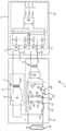
도 2는 본 발명의 실시예에 따른, 정전기 집진기에 파워를 공급하기 위한 고-전압 파워 서플라이 시스템의 개략적 회로도를 예시하고;
도 3A는 본 발명의 실시예에 따른, 발진 싸이클 동안 펄스 형성 회로의 스토리지 커패시터에 걸친 전압을 나타내는 개략적 파형을 예시하고;
도 3B는 본 발명의 실시예에 따른, 발진 싸이클 동안 펄스 서플라이 회로 내의 아울러 ESP로의 전류를 나타내는 개략적 파형을 예시하고;
도 3C는 본 발명의 실시예에 따른, 발진 싸이클 동안 고전압 파워 서플라이 시스템에 연결된 ESP에 걸친 전압을 나타내는 개략적 파형을 예시하고;
도 4는 도 2에서의 펄스 서플라이 회로의 대안적 실시예의 개략적 블록도이다.
Claims (16)
- 정전기 집진기(electrostatic precipitator)(10)에 파워(power)를 공급하는데 적합한 DC 베이스 전압(DC base voltage)에 중첩(superimpose)되는 고-전압 펄스(high-voltage pulse)들을 발생시키기 위한 파워 서플라이 시스템(power supply system)(1)으로서,
상기 파워 서플라이 시스템은,
제 1 AC 서플라이 전압(AC supply voltage) 및 제 2 AC 서플라이 전압을 발생시키도록 되어 있는 AC 서플라이 회로(AC supply circuit)(2)와;
상기 AC 서플라이 회로(2)와 상기 정전기 집진기(10) 사이에 연결될 수 있는 DC 서플라이 회로(DC supply circuit)(5)와; 그리고
상기 AC 서플라이 회로(2)와 상기 정전기 집진기(10) 사이에 연결될 수 있는 펄스 서플라이 회로(pulse supply circuit)(6)를 포함하고,
상기 DC 서플라이 회로는,
상기 제 1 AC 서플라이 전압을 상기 DC 베이스 전압으로 변환 및 전환시키기 위한 제 1 변압기(transformer)(7) 및 제 1 정류기 회로(rectifier circuit)(8)를 포함하고,
상기 펄스 서플라이 회로(6)는,
상기 제 2 AC 서플라이 전압을 상기 고-전압 펄스들을 발생시키기에 충분한 DC 펄스 서플라이 전압(DC pulse supply voltage)으로 변환 및 전환시키기 위한 제 2 변압기(9) 및 제 2 정류기 회로(11)와, 그리고
상기 제 2 정류기 회로(11)와 상기 정전기 집진기(10) 사이에 연결될 수 있는 펄스 형성 회로(pulse forming circuit)(12; 12')를 포함하고,
상기 펄스 형성 회로는 추가적인 전압 변환 없이 상기 고-전압 펄스들을 발생시키도록 되어 있고,
상기 AC 서플라이 회로는 상기 제 1 AC 서플라이 전압 및 상기 제 2 AC 서플라이 전압 각각의 주파수가 100 Hz 내지 5000 Hz 범위에 있도록 구성되는 것을 특징으로 하는 파워 서플라이 시스템(1). - 제1항에 있어서,
상기 펄스 형성 회로(12; 12')는, 적어도 하나의 사이리스터(thyristor)(25)와, 그리고 상기 적어도 하나의 사이리스터와 역-병렬(anti-parallel)로 연결된 적어도 하나의 다이오드(diode)(26)를 포함하는 것을 특징으로 하는 고-전압 파워 서플라이 시스템(1). - 제1항 또는 제2항에 있어서,
상기 AC 서플라이 회로(2)는,
DC 피드 전압(DC feed voltage)을 상기 제 1 AC 서플라이 전압으로 전환시키도록 되어 있는 제 1 파워 인버터(power inverter)(3)와, 그리고
상기 DC 피드 전압을 상기 제 2 AC 서플라이 전압으로 전환시키도록 되어 있는 제 2 파워 인버터(4)를 포함하고,
상기 제 1 파워 인버터 및 상기 제 2 파워 인버터는 상기 제 1 AC 서플라이 전압 및 상기 제 2 AC 서플라이 전압 각각의 주파수를 100 Hz 내지 5000 Hz 범위에 있게 제어하도록 되어 있는 것을 특징으로 하는 고-전압 파워 서플라이 시스템. - 제3항에 있어서,
상기 제 1 파워 인버터(3)는 IGBT 또는 MOSFET과 같은 반도체 파워 스위치(semiconductor power switch)들을 포함하는 풀 브리지(full bridge) 혹은 하프 브리지(half bridge) 단상 인버터(single phase inverter)인 것을 특징으로 하는 고-전압 파워 서플라이 시스템(1). - 제3항 또는 제4항에 있어서,
상기 제 2 파워 인버터(4)는 IGBT 또는 MOSFET과 같은 반도체 파워 스위치들을 포함하는 풀 브리지 혹은 하프 브리지 단상 인버터인 것을 특징으로 하는 고-전압 파워 서플라이 시스템(1). - 선행하는 항들 중 어느 하나의 항에 있어서,
상기 DC 베이스 전압과 상기 고-전압 펄스들은 상기 파워 서플라이 시스템의 출력에서 병렬로 연결되는 것을 특징으로 하는 고-전압 파워 서플라이 시스템(1). - 제6항에 있어서,
상기 펄스 형성 회로(12)는,
상기 제 2 정류기 회로(11)의 출력 단자(output terminal)들 사이에 연결되는 스토리지 커패시터(storage capacitor)(21)와,
상기 파워 서플라이 시스템의 출력에 직렬로 연결되는 제 1 직렬 인덕턴스(series inductance)(23) 및 결합 커패시터(coupling capacitor)(27)와, 그리고
상기 스토리지 커패시터(21)와 상기 제 1 직렬 인덕턴스(23) 사이에 직렬로 연결되는 고전압 스위칭 회로(high voltage switching circuit)(24)를 포함하는 것을 특징으로 하는 고-전압 파워 서플라이 시스템(1). - 제6항에 있어서,
상기 펄스 형성 회로(12')는,
상기 제 2 정류기 회로(11)의 출력 단자들 사이에 연결되는 고전압 스위칭 회로(24')와,
상기 파워 서플라이 시스템의 출력에 직렬로 연결되는 제 1 직렬 인덕턴스(23) 및 결합 커패시터(27)와, 그리고
상기 고전압 스위칭 회로(24')와 상기 제 1 직렬 인덕턴스(23) 사이에 직렬로 연결되는 스토리지 커패시터(21')를 포함하는 것을 특징으로 하는 고-전압 파워 서플라이 시스템(1). - 제7항 또는 제8항에 있어서,
상기 고전압 스위칭 회로는, 적어도 하나의 사이리스터(25)와, 그리고 상기 적어도 하나의 사이리스터와 역-병렬로 연결된 적어도 하나의 다이오드(26)를 포함하는 것을 특징으로 하는 고-전압 파워 서플라이 시스템(1). - 제7항 내지 제9항 중 하나의 항에 있어서,
상기 펄스 형성 회로(12; 12')는 또한,
상기 고전압 스위칭 회로(24; 24') 및 상기 스토리지 커패시터(21; 21')와 병렬로 연결되는 보호 브랜치(protective branch)(31)를 포함하고,
상기 보호 브랜치(31)는 상기 고전압 스위칭 회로(24)에 걸친 전압 피크(voltage peak)들을 제한하기 위한 제 1 저항(resistance)(33) 및 직렬 다이오드(32)를 포함하는 것을 특징으로 하는 고-전압 파워 서플라이 시스템(1). - 제5항 내지 제8항 중 하나의 항에 있어서,
상기 펄스 형성 회로(12; 12')는 또한,
상기 고전압 스위칭 회로(24) 및 상기 스토리지 커패시터(21)와 병렬로 연결되는 복원 브랜치(restoring branch)(34)를 포함하고,
상기 복원 브랜치(34)는 펄스들 사이에서 상기 결합 커패시터(27)의 전하를 복원시키기 위한 제 2 저항(36) 및 제 2 직렬 인덕턴스(35)를 포함하는 것을 특징으로 하는 고-전압 파워 서플라이 시스템(1). - 제9항에 있어서,
상기 제 2 직렬 인덕턴스(35)는 0.1 H 내지 10 H 범위에 있는 인덕턴스 값을 갖는 것을 특징으로 하는 고-전압 파워 서플라이 시스템(1). - 선행하는 항들 중 어느 하나의 항에 있어서,
상기 제 1 AC 서플라이 전압 및 상기 제 2 AC 서플라이 전압 각각의 주파수는 200 Hz 내지 2000 Hz 범위에 있는 것을 특징으로 하는 고-전압 파워 서플라이 시스템(1). - 선행하는 항들 중 어느 하나의 항에 있어서,
상기 고-전압 파워 서플라이 시스템(1)은 또한,
상기 DC 서플라이 회로(5)의 상기 제 1 변압기(7)와 상기 제 1 파워 인버터(3) 사이에 연결되는 제 1 직렬 커패시터(41)와, 그리고
상기 펄스 서플라이 회로의 상기 제 2 변압기(9)와 상기 제 2 파워 인버터(4) 사이에 연결되는 제 2 직렬 커패시터(42)를 포함하는 것을 특징으로 하는 고-전압 파워 서플라이 시스템(1). - 선행하는 항들 중 어느 하나의 항에 있어서,
상기 제 1 AC 서플라이 전압의 주파수는 상기 제 2 AC 서플라이 전압의 주파수보다 높은 것을 특징으로 하는 고-전압 파워 서플라이 시스템(1). - 선행하는 항들 중 어느 하나의 항에 있어서,
상기 고-전압 파워 서플라이 시스템(1)은 정전기 집진기(10)에 연결되는 것을 특징으로 하는 고-전압 파워 서플라이 시스템(1).
Applications Claiming Priority (3)
| Application Number | Priority Date | Filing Date | Title |
|---|---|---|---|
| EP17195478.7 | 2017-10-09 | ||
| EP17195478 | 2017-10-09 | ||
| PCT/EP2018/077380 WO2019072786A1 (en) | 2017-10-09 | 2018-10-09 | HIGH VOLTAGE POWER SUPPLY SYSTEM |
Publications (2)
| Publication Number | Publication Date |
|---|---|
| KR20200058547A true KR20200058547A (ko) | 2020-05-27 |
| KR102579842B1 KR102579842B1 (ko) | 2023-09-18 |
Family
ID=60043098
Family Applications (1)
| Application Number | Title | Priority Date | Filing Date |
|---|---|---|---|
| KR1020207012833A Active KR102579842B1 (ko) | 2017-10-09 | 2018-10-09 | 고-전압 파워 서플라이 시스템 |
Country Status (10)
| Country | Link |
|---|---|
| US (1) | US11192119B2 (ko) |
| EP (1) | EP3612310B1 (ko) |
| JP (1) | JP7286660B2 (ko) |
| KR (1) | KR102579842B1 (ko) |
| CN (1) | CN111565853B (ko) |
| CA (1) | CA3078269A1 (ko) |
| PL (1) | PL3612310T3 (ko) |
| RS (1) | RS61186B1 (ko) |
| RU (1) | RU2770756C2 (ko) |
| WO (1) | WO2019072786A1 (ko) |
Families Citing this family (4)
| Publication number | Priority date | Publication date | Assignee | Title |
|---|---|---|---|---|
| US11793353B2 (en) | 2017-03-03 | 2023-10-24 | SoMi LLC | Heating container |
| WO2021230857A1 (en) * | 2020-05-12 | 2021-11-18 | Air Quality Engineering, Inc. | Electrostatic precipitation air cleaning system |
| CN114062819B (zh) * | 2021-11-16 | 2024-05-10 | 许继集团有限公司 | 一种适用于同相供电装置功率模块的试验系统及其控制方法 |
| CN116916612A (zh) * | 2023-07-07 | 2023-10-20 | 山东省信息产业服务有限公司 | 一种通信机房散热除尘装置及系统 |
Citations (4)
| Publication number | Priority date | Publication date | Assignee | Title |
|---|---|---|---|---|
| JPH0852380A (ja) * | 1994-08-11 | 1996-02-27 | Mitsubishi Heavy Ind Ltd | 電気集塵装置 |
| KR0137389B1 (ko) * | 1993-12-28 | 1998-04-25 | 오기노 카네오 | 전기 집진장치 |
| WO2013056406A1 (zh) * | 2011-10-18 | 2013-04-25 | 艾尼科环保技术(安徽)有限公司 | 一种静电除尘器用高压中频电源及其供电方法 |
| US20140168848A1 (en) * | 2012-12-14 | 2014-06-19 | Redkoh Industries, Inc. | Systems and methods of power conversion for electrostatic precipitators |
Family Cites Families (25)
| Publication number | Priority date | Publication date | Assignee | Title |
|---|---|---|---|---|
| US4052177A (en) | 1975-03-03 | 1977-10-04 | Nea-Lindberg A/S | Electrostatic precipitator arrangements |
| JPS5861843A (ja) * | 1981-09-12 | 1983-04-13 | Senichi Masuda | 極短パルス高電圧発生装置 |
| DE3246057A1 (de) * | 1982-12-13 | 1984-06-14 | Metallgesellschaft Ag, 6000 Frankfurt | Einrichtung zur spannungsversorgung eines elektrofilters |
| JPS59145060A (ja) * | 1983-02-07 | 1984-08-20 | Sumitomo Heavy Ind Ltd | 電気集塵機用パルス電源 |
| JP2561453B2 (ja) * | 1983-02-07 | 1996-12-11 | 住友重機械工業株式会社 | 電気集塵機用パルス電源 |
| US4600411A (en) | 1984-04-06 | 1986-07-15 | Lucidyne, Inc. | Pulsed power supply for an electrostatic precipitator |
| GB8431293D0 (en) * | 1984-12-12 | 1985-01-23 | Smidth & Co As F L | Controlling pulse frequency of electrostatic precipitator |
| DE3511622A1 (de) * | 1985-03-29 | 1986-10-09 | Metallgesellschaft Ag, 6000 Frankfurt | Verfahren und einrichtung zur versorgung eines elektroabscheiders mit hochspannungsimpulsen |
| DE3573374D1 (en) * | 1985-07-15 | 1989-11-09 | Kraftelektronik Ab | An electrostatic dust precipitator |
| JP2828958B2 (ja) * | 1996-02-29 | 1998-11-25 | 住友重機械工業株式会社 | パルス荷電型電気集塵機用回路及び電気集塵機 |
| WO2000016906A1 (en) * | 1998-09-18 | 2000-03-30 | Fls Miljø A/S | A method of operating an electrostatic precipitator |
| RU2207191C2 (ru) * | 2001-04-24 | 2003-06-27 | Государственное унитарное предприятие "Всероссийский электротехнический институт им. В.И. Ленина" | Способ питания электрофильтра и устройство для его реализации |
| JP3623181B2 (ja) | 2001-08-27 | 2005-02-23 | オリジン電気株式会社 | 高電圧半導体スイッチ装置および高電圧発生装置 |
| DE10145993A1 (de) | 2001-09-18 | 2003-04-24 | Siemens Ag | Hochspannungs-Pulsgenerator für ein Elektrofilter |
| ES2368913T3 (es) * | 2004-10-26 | 2011-11-23 | Flsmidth A/S | Sistema generador de impulsos para precipitador electrostático. |
| ATE456183T1 (de) | 2006-06-23 | 2010-02-15 | Alstom Technology Ltd | Stromversorger für elektrostatischen abscheider |
| RU68819U1 (ru) * | 2007-07-09 | 2007-11-27 | Федеральное государственное унитарное предприятие "Всероссийский электротехнический институт имени В.И. Ленина" | Устройство для питания электрофильтра |
| CN102755931A (zh) * | 2011-12-21 | 2012-10-31 | 厦门锐传科技有限公司 | 静电除尘用可变频中频电源 |
| WO2013112613A1 (en) * | 2012-01-23 | 2013-08-01 | Utah State University | Dual side control for inductive power transfer |
| CN102847610B (zh) * | 2012-08-23 | 2013-05-01 | 襄阳九鼎昊天环保设备有限公司 | 一种静电除尘器用直流复合脉冲高压电源 |
| CN102820782A (zh) * | 2012-09-18 | 2012-12-12 | 中国兵器工业第二0二研究所 | 带有功率开关元件保护电路的直流升压变换器 |
| CN103028494B (zh) * | 2012-12-19 | 2016-09-21 | 浙江连成环保科技有限公司 | 一种静电除尘脉冲电源控制系统 |
| CN203018208U (zh) * | 2012-12-20 | 2013-06-26 | 浙江连成环保科技有限公司 | 一种静电除尘脉冲电源控制系统 |
| CN103350031A (zh) * | 2013-06-09 | 2013-10-16 | 浙江菲达环保科技股份有限公司 | 一种电除尘用脉冲电源 |
| CN105080722B (zh) * | 2015-07-22 | 2017-06-06 | 西安交通大学 | 可抗干扰的静电除尘用直流脉冲电源 |
-
2018
- 2018-10-09 RS RS20201502A patent/RS61186B1/sr unknown
- 2018-10-09 CN CN201880065641.1A patent/CN111565853B/zh active Active
- 2018-10-09 WO PCT/EP2018/077380 patent/WO2019072786A1/en not_active Ceased
- 2018-10-09 US US16/754,510 patent/US11192119B2/en active Active
- 2018-10-09 JP JP2020540847A patent/JP7286660B2/ja active Active
- 2018-10-09 PL PL18780152T patent/PL3612310T3/pl unknown
- 2018-10-09 RU RU2020115092A patent/RU2770756C2/ru active
- 2018-10-09 KR KR1020207012833A patent/KR102579842B1/ko active Active
- 2018-10-09 CA CA3078269A patent/CA3078269A1/en active Pending
- 2018-10-09 EP EP18780152.7A patent/EP3612310B1/en active Active
Patent Citations (4)
| Publication number | Priority date | Publication date | Assignee | Title |
|---|---|---|---|---|
| KR0137389B1 (ko) * | 1993-12-28 | 1998-04-25 | 오기노 카네오 | 전기 집진장치 |
| JPH0852380A (ja) * | 1994-08-11 | 1996-02-27 | Mitsubishi Heavy Ind Ltd | 電気集塵装置 |
| WO2013056406A1 (zh) * | 2011-10-18 | 2013-04-25 | 艾尼科环保技术(安徽)有限公司 | 一种静电除尘器用高压中频电源及其供电方法 |
| US20140168848A1 (en) * | 2012-12-14 | 2014-06-19 | Redkoh Industries, Inc. | Systems and methods of power conversion for electrostatic precipitators |
Also Published As
| Publication number | Publication date |
|---|---|
| EP3612310A1 (en) | 2020-02-26 |
| WO2019072786A1 (en) | 2019-04-18 |
| JP2020536737A (ja) | 2020-12-17 |
| US11192119B2 (en) | 2021-12-07 |
| CA3078269A1 (en) | 2019-04-18 |
| PL3612310T3 (pl) | 2021-06-28 |
| RU2020115092A3 (ko) | 2021-12-28 |
| JP7286660B2 (ja) | 2023-06-05 |
| US20200316612A1 (en) | 2020-10-08 |
| RS61186B1 (sr) | 2021-01-29 |
| CN111565853A (zh) | 2020-08-21 |
| CN111565853B (zh) | 2022-09-27 |
| EP3612310B1 (en) | 2020-09-30 |
| KR102579842B1 (ko) | 2023-09-18 |
| RU2770756C2 (ru) | 2022-04-21 |
| RU2020115092A (ru) | 2021-11-12 |
Similar Documents
| Publication | Publication Date | Title |
|---|---|---|
| CN102847610B (zh) | 一种静电除尘器用直流复合脉冲高压电源 | |
| KR102579842B1 (ko) | 고-전압 파워 서플라이 시스템 | |
| CN103350031A (zh) | 一种电除尘用脉冲电源 | |
| CN105080723B (zh) | 一种大功率高压脉冲产生电路 | |
| JPH07232102A (ja) | 電気集塵装置 | |
| CN205092785U (zh) | 三相电源 | |
| CN104393766A (zh) | 一种除尘用叠加式电源控制系统 | |
| US8331118B2 (en) | Generator and method for generating a direct current high voltage, and dust collector using such generator | |
| KR20180095163A (ko) | 마이크로 펄스 전원 장치 및 이를 이용한 전기 집진 장치 | |
| KR101675018B1 (ko) | 마이크로 펄스 하전 방식의 집진기용 전원장치 | |
| EP2268407B1 (en) | High voltage power supply for electrostatic precipitator | |
| CN202962664U (zh) | 一种静电除尘器用直流复合脉冲高压电源 | |
| CN214851004U (zh) | 电除尘器用幅值平稳的高能脉冲供电系统 | |
| JP7840563B2 (ja) | 集塵装置 | |
| CN109889079B (zh) | 一种由可控硅控制的纳秒级脉冲电源 | |
| CN203355882U (zh) | 一种电除尘用脉冲电源 | |
| CN113054857A (zh) | 电除尘器用幅值平稳的高能脉冲供电系统 | |
| KR102515338B1 (ko) | 전력 스위치를 이용한 고전압 펄스 발생 회로 및 이를 포함하는 전기 집진기 | |
| CN219351554U (zh) | 一种变频恒流源及静电除尘器 | |
| CN106026715A (zh) | 一种凝聚器用高频恒流双极电源电路 | |
| Despotović et al. | Contemporary Approach to Power of Electrostatic Precipitators | |
| CN207839196U (zh) | 一种用于电除尘器的脉冲电源 | |
| US20060279974A1 (en) | AC line isolated DC high frequency low power converter | |
| KR20030084229A (ko) | 전력 절약형 전기 집진기 장치 | |
| CN117895924A (zh) | 一种用于静电消除器的高压脉冲发生装置 |
Legal Events
| Date | Code | Title | Description |
|---|---|---|---|
| PA0105 | International application |
Patent event date: 20200504 Patent event code: PA01051R01D Comment text: International Patent Application |
|
| PG1501 | Laying open of application | ||
| PA0201 | Request for examination |
Patent event code: PA02012R01D Patent event date: 20211008 Comment text: Request for Examination of Application |
|
| E902 | Notification of reason for refusal | ||
| PE0902 | Notice of grounds for rejection |
Comment text: Notification of reason for refusal Patent event date: 20230210 Patent event code: PE09021S01D |
|
| E701 | Decision to grant or registration of patent right | ||
| PE0701 | Decision of registration |
Patent event code: PE07011S01D Comment text: Decision to Grant Registration Patent event date: 20230821 |
|
| GRNT | Written decision to grant | ||
| PR0701 | Registration of establishment |
Comment text: Registration of Establishment Patent event date: 20230913 Patent event code: PR07011E01D |
|
| PR1002 | Payment of registration fee |
Payment date: 20230914 End annual number: 3 Start annual number: 1 |
|
| PG1601 | Publication of registration |