KR20200069588A - 차량 현가 장치의 상태 감시 장치 - Google Patents
차량 현가 장치의 상태 감시 장치 Download PDFInfo
- Publication number
- KR20200069588A KR20200069588A KR1020180156809A KR20180156809A KR20200069588A KR 20200069588 A KR20200069588 A KR 20200069588A KR 1020180156809 A KR1020180156809 A KR 1020180156809A KR 20180156809 A KR20180156809 A KR 20180156809A KR 20200069588 A KR20200069588 A KR 20200069588A
- Authority
- KR
- South Korea
- Prior art keywords
- piezoelectric
- spring
- harvest
- leaf spring
- plate
- Prior art date
- Legal status (The legal status is an assumption and is not a legal conclusion. Google has not performed a legal analysis and makes no representation as to the accuracy of the status listed.)
- Granted
Links
- 239000000725 suspension Substances 0.000 title claims abstract description 37
- 238000012544 monitoring process Methods 0.000 title claims abstract description 10
- 238000003306 harvesting Methods 0.000 claims abstract description 90
- 238000012806 monitoring device Methods 0.000 claims abstract description 23
- 239000000463 material Substances 0.000 claims abstract description 9
- 230000035939 shock Effects 0.000 claims abstract description 6
- 238000000034 method Methods 0.000 claims description 17
- 239000004020 conductor Substances 0.000 claims description 16
- 238000005336 cracking Methods 0.000 claims description 7
- 230000001186 cumulative effect Effects 0.000 claims description 7
- 238000005259 measurement Methods 0.000 claims description 6
- 238000010030 laminating Methods 0.000 claims description 2
- 230000006835 compression Effects 0.000 description 7
- 238000007906 compression Methods 0.000 description 7
- 230000005611 electricity Effects 0.000 description 5
- 239000011248 coating agent Substances 0.000 description 4
- 238000000576 coating method Methods 0.000 description 4
- 238000010586 diagram Methods 0.000 description 3
- 239000002184 metal Substances 0.000 description 3
- 238000006243 chemical reaction Methods 0.000 description 2
- 239000000446 fuel Substances 0.000 description 2
- 239000011810 insulating material Substances 0.000 description 2
- 230000000694 effects Effects 0.000 description 1
- 238000010292 electrical insulation Methods 0.000 description 1
- 238000011156 evaluation Methods 0.000 description 1
- 150000002500 ions Chemical group 0.000 description 1
- 238000003475 lamination Methods 0.000 description 1
- 238000012423 maintenance Methods 0.000 description 1
- 238000012986 modification Methods 0.000 description 1
- 230000004048 modification Effects 0.000 description 1
- 238000010422 painting Methods 0.000 description 1
- 230000008929 regeneration Effects 0.000 description 1
- 238000011069 regeneration method Methods 0.000 description 1
- 238000012360 testing method Methods 0.000 description 1
Images



Classifications
-
- B—PERFORMING OPERATIONS; TRANSPORTING
- B60—VEHICLES IN GENERAL
- B60G—VEHICLE SUSPENSION ARRANGEMENTS
- B60G17/00—Resilient suspensions having means for adjusting the spring or vibration-damper characteristics, for regulating the distance between a supporting surface and a sprung part of vehicle or for locking suspension during use to meet varying vehicular or surface conditions, e.g. due to speed or load
- B60G17/015—Resilient suspensions having means for adjusting the spring or vibration-damper characteristics, for regulating the distance between a supporting surface and a sprung part of vehicle or for locking suspension during use to meet varying vehicular or surface conditions, e.g. due to speed or load the regulating means comprising electric or electronic elements
- B60G17/019—Resilient suspensions having means for adjusting the spring or vibration-damper characteristics, for regulating the distance between a supporting surface and a sprung part of vehicle or for locking suspension during use to meet varying vehicular or surface conditions, e.g. due to speed or load the regulating means comprising electric or electronic elements characterised by the type of sensor or the arrangement thereof
- B60G17/01941—Resilient suspensions having means for adjusting the spring or vibration-damper characteristics, for regulating the distance between a supporting surface and a sprung part of vehicle or for locking suspension during use to meet varying vehicular or surface conditions, e.g. due to speed or load the regulating means comprising electric or electronic elements characterised by the type of sensor or the arrangement thereof characterised by the use of piezoelectric elements, e.g. sensors or actuators
-
- B—PERFORMING OPERATIONS; TRANSPORTING
- B60—VEHICLES IN GENERAL
- B60G—VEHICLE SUSPENSION ARRANGEMENTS
- B60G11/00—Resilient suspensions characterised by arrangement, location or kind of springs
- B60G11/02—Resilient suspensions characterised by arrangement, location or kind of springs having leaf springs only
-
- B—PERFORMING OPERATIONS; TRANSPORTING
- B60—VEHICLES IN GENERAL
- B60G—VEHICLE SUSPENSION ARRANGEMENTS
- B60G13/00—Resilient suspensions characterised by arrangement, location or type of vibration dampers
- B60G13/14—Resilient suspensions characterised by arrangement, location or type of vibration dampers having dampers accumulating utilisable energy, e.g. compressing air
-
- B—PERFORMING OPERATIONS; TRANSPORTING
- B60—VEHICLES IN GENERAL
- B60G—VEHICLE SUSPENSION ARRANGEMENTS
- B60G17/00—Resilient suspensions having means for adjusting the spring or vibration-damper characteristics, for regulating the distance between a supporting surface and a sprung part of vehicle or for locking suspension during use to meet varying vehicular or surface conditions, e.g. due to speed or load
- B60G17/015—Resilient suspensions having means for adjusting the spring or vibration-damper characteristics, for regulating the distance between a supporting surface and a sprung part of vehicle or for locking suspension during use to meet varying vehicular or surface conditions, e.g. due to speed or load the regulating means comprising electric or electronic elements
- B60G17/018—Resilient suspensions having means for adjusting the spring or vibration-damper characteristics, for regulating the distance between a supporting surface and a sprung part of vehicle or for locking suspension during use to meet varying vehicular or surface conditions, e.g. due to speed or load the regulating means comprising electric or electronic elements characterised by the use of a specific signal treatment or control method
-
- B—PERFORMING OPERATIONS; TRANSPORTING
- B60—VEHICLES IN GENERAL
- B60G—VEHICLE SUSPENSION ARRANGEMENTS
- B60G2202/00—Indexing codes relating to the type of spring, damper or actuator
- B60G2202/10—Type of spring
- B60G2202/11—Leaf spring
-
- B—PERFORMING OPERATIONS; TRANSPORTING
- B60—VEHICLES IN GENERAL
- B60G—VEHICLE SUSPENSION ARRANGEMENTS
- B60G2204/00—Indexing codes related to suspensions per se or to auxiliary parts
- B60G2204/40—Auxiliary suspension parts; Adjustment of suspensions
- B60G2204/43—Fittings, brackets or knuckles
- B60G2204/4306—Bracket or knuckle for rigid axles, e.g. for clamping
- B60G2204/43065—U-shaped bolts crossing each other
-
- B—PERFORMING OPERATIONS; TRANSPORTING
- B60—VEHICLES IN GENERAL
- B60G—VEHICLE SUSPENSION ARRANGEMENTS
- B60G2600/00—Indexing codes relating to particular elements, systems or processes used on suspension systems or suspension control systems
- B60G2600/04—Means for informing, instructing or displaying
- B60G2600/042—Monitoring means
-
- B—PERFORMING OPERATIONS; TRANSPORTING
- B60—VEHICLES IN GENERAL
- B60Y—INDEXING SCHEME RELATING TO ASPECTS CROSS-CUTTING VEHICLE TECHNOLOGY
- B60Y2400/00—Special features of vehicle units
- B60Y2400/30—Sensors
- B60Y2400/308—Electric sensors
- B60Y2400/3086—Electric voltages sensors
Landscapes
- Engineering & Computer Science (AREA)
- Mechanical Engineering (AREA)
- Testing Of Devices, Machine Parts, Or Other Structures Thereof (AREA)
- Springs (AREA)
Abstract
Description
도 2는 도 1에서 'A' 부분을 확대하여 도시한 사시도이다.
도 3은 본 발명의 감시 대상인 판스프링의 상태를 예시한 도면이다.
도 4는 압전층에 의한 전기 생성의 원리를 설명하기 위한 도면이다.
도 5는 본 발명에서 판스프링의 압전 하베스트층을 유볼트의 일단부에 전기적으로 접속한 상태를 예시한 도면이다.
도 6은 본 발명에서 전압측정부와 배터리를 연결한 상태를 예시한 도면이다.
도 7은 본 발명에서 유볼트에 크랙이 발생한 상태를 예시한 도면이다.
도 8은 본 발명에서 크랙 발생 여부를 감지하기 위한 회로 구성을 예시한 도면이다.
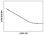
도 9는 본 발명에서 판스프링의 발생 응력과 판스프링의 수명을 나타내는 S-N 곡선의 예를 나타낸 도면이다.
도 10은 본 발명에서 표시장치를 통해 상태 정보가 표시되는 예를 나타낸 도면이다.


11 : 스프링 판 20 : 액슬
31 : 유볼트 32 : 너트
33 : 와셔 33a: 절연층
34 : 지지체 41 : 압전 하베스트층
42 : 전기도선 43 : 전기도선
44 : 전기도선 45 : 전기도선
46 : AND 논리 게이트 소자 47 : OR 논리 게이트 소자
51 : 전압측정부 52 : 배터리
60 : 제어부 70 : 표시장치
Claims (15)
- 차량 현가 장치의 판스프링에 대한 상태 감시 장치로서,
상기 판스프링을 구성하는 스프링 판의 표면에 압전물질을 적층 형성하여서 구비되고, 차량 주행 중 진동 또는 충격으로 인해 판스프링의 스프링 판이 변형될 때 전기에너지를 생성하는 상기 압전 하베스트층; 및
상기 압전 하베스트층에 전기적으로 접속되어 압전 하베스트층에서 발생하는 전기 신호를 입력받아 전기 신호로부터 판스프링의 상태를 추정하는 제어부를 포함하는 차량 현가 장치의 상태 감시 장치.
- 청구항 1에 있어서,
상기 스프링 판의 표면에 서로 정해진 간격을 두고 이격 배치되어 전기적으로 분리되는 복수 개의 압전 하베스트층이 구비되고,
상기 복수 개의 압전 하베스트층은 스프링 판에서 길이방향을 따라 길게 배치되는 나란한 라인 형상으로 형성되는 것을 특징으로 하는 차량 현가 장치의 상태 감시 장치.
- 청구항 2에 있어서,
상기 복수 개의 압전 하베스트층은 스프링 판의 상면과 하면, 그리고 양 옆면에 모두 형성되는 것을 특징으로 하는 차량 현가 장치의 상태 감시 장치.
- 청구항 2에 있어서,
상기 제어부는
상기 복수 개의 압전 하베스트층이 각각 전기도선을 통해 병렬로 접속되는 AND 논리 게이트 소자;
상기 복수 개의 압전 하베스트층이 각각 전기도선을 통해 병렬로 접속되는 OR 논리 게이트 소자; 및
상기 AND 논리 게이트 소자 및 OR 논리 게이트 소자의 출력으로부터 판스프링의 상태를 판단하는 판단부를 포함하는 것을 특징으로 하는 차량 현가 장치의 상태 감시 장치.
- 청구항 4에 있어서,
상기 복수 개의 압전 하베스트층 중 적어도 하나에서 전기도선을 통해 일정 레벨 미만의 전압이 상기 AND 논리 게이트 소자에 인가되면, 상기 AND 논리 게이트 소자는 로우 신호를 출력하고,
상기 복수 개의 압전 하베스트층 중 적어도 하나에서 전기도선을 통해 일정 레벨 이상의 전압이 상기 OR 논리 게이트 소자에 인가되면, 상기 OR 논리 게이트 소자는 하이 신호를 출력하도록 된 것을 특징으로 하는 차량 현가 장치의 상태 감시 장치.
- 청구항 5에 있어서,
상기 판단부는
상기 AND 논리 게이트 소자에서 로우 신호가 입력되고, 상기 OR 논리 게이트 소자에서 하이 신호가 입력되면, 상기 판스프링의 상태로서 판스프링에서 크랙 또는 파단이 발생한 것으로 판단하는 것을 특징으로 하는 차량 현가 장치의 상태 감시 장치.
- 청구항 6에 있어서,
상기 제어부는
상기 판스프링에서 크랙이 발생한 것으로 판단한 후,
상기 각 압전 하베스트층으로부터 전기도선을 통해 입력되는 전압 신호로부터 판스프링에서의 크랙 발생 정보를 취득하고,
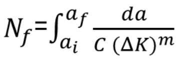
상기 취득된 크랙 발생 정보로부터 미리 정해진 수명 예측식을 이용하여, 상기 판스프링의 상태를 나타내는 판스프링의 예상 수명을 결정하도록 된 것을 특징으로 하는 차량 현가 장치의 상태 감시 장치.
- 청구항 1에 있어서,
상기 압전 하베스트층이 전기도선을 통해 배터리에 연결되어, 상기 압전 하베스트층에서 생성된 전기에너지가 배터리에 저장될 수 있도록 된 것을 특징으로 하는 차량 현가 장치의 상태 감시 장치.
- 청구항 8에 있어서,
상기 압전 하베스트층이 상기 판스프링과 차량의 액슬을 체결하고 있는 유볼트에 전기도선을 통해 전기적으로 접속되고, 상기 유볼트가 별도의 전기도선을 통해 상기 배터리에 연결되는 것을 특징으로 하는 차량 현가 장치의 상태 감시 장치.
- 청구항 1에 있어서,
상기 압전 하베스트층이 상기 판스프링과 차량의 액슬을 체결하고 있는 유볼트의 일단부 위치에 전기도선을 통해 전기적으로 접속되고,
상기 전기도선이 접속된 유볼트의 일단부 위치와, 상기 유볼트에서 상기 일단부 위치로부터 정해진 거리를 두고 떨어진 위치에 각각 별도의 전기도선을 통해 전압측정부가 접속되며,
상기 전압측정부에서 측정된 상기 유볼트의 두 위치 사이의 전압을 제어부가 입력받아 상기 측정된 전압으로부터 판스프링의 상태를 추정하는 것을 특징으로 하는 차량 현가 장치의 상태 감시 장치.
- 청구항 10에 있어서,
상기 압전 하베스트층이,
상기 유볼트의 일단부 위치로서, 상기 유볼트의 일단부에 결합된 너트 또는 상기 너트와 액슬 사이의 와셔에,
상기 전기도선을 통해 전기적으로 접속되는 것을 특징으로 하는 차량 현가 장치의 상태 감시 장치.
- 청구항 11에 있어서,
상기 와셔에서 상기 액슬에 접촉하는 표면에 절연층이 구비되어, 와셔와 액슬 사이가 전기적으로 절연된 상태를 유지하도록 된 것을 특징으로 하는 차량 현가 장치의 상태 감시 장치.
- 청구항 10 또는 청구항 11에 있어서,
상기 제어부는 전압측정부에서 측정된 전압을 확인하여 상기 유볼트의 크랙 발생 또는 상기 너트의 풀림을 감지하는 것을 특징으로 하는 차량 현가 장치의 상태 감시 장치.
- 청구항 10에 있어서,
상기 제어부는
상기 전압측정부에 의해 측정된 전압으로부터 판스프링에서 발생하는 응력을 계산하고,
상기 전압측정부에 의해 측정된 전압 중 기설정 값 이상의 전압을 누적 합산하여 판스프링의 누적 손상량을 결정하며,
상기 결정된 누적 손상량에 해당하는 응력 대 수명 곡선(S-N 곡선)을 이용하여 상기 계산된 응력으로부터 판스프링의 예상 수명을 결정하는 것을 특징으로 하는 차량 현가 장치의 상태 감시 장치.
- 청구항 1에 있어서,
상기 제어부에서 추정된 판스프링의 상태를 표시하는 표시장치를 더 포함하는 것을 특징으로 하는 차량 현가 장치의 상태 감시 장치.
Priority Applications (1)
| Application Number | Priority Date | Filing Date | Title |
|---|---|---|---|
| KR1020180156809A KR102563606B1 (ko) | 2018-12-07 | 2018-12-07 | 차량 현가 장치의 상태 감시 장치 |
Applications Claiming Priority (1)
| Application Number | Priority Date | Filing Date | Title |
|---|---|---|---|
| KR1020180156809A KR102563606B1 (ko) | 2018-12-07 | 2018-12-07 | 차량 현가 장치의 상태 감시 장치 |
Publications (2)
| Publication Number | Publication Date |
|---|---|
| KR20200069588A true KR20200069588A (ko) | 2020-06-17 |
| KR102563606B1 KR102563606B1 (ko) | 2023-08-03 |
Family
ID=71405415
Family Applications (1)
| Application Number | Title | Priority Date | Filing Date |
|---|---|---|---|
| KR1020180156809A Active KR102563606B1 (ko) | 2018-12-07 | 2018-12-07 | 차량 현가 장치의 상태 감시 장치 |
Country Status (1)
| Country | Link |
|---|---|
| KR (1) | KR102563606B1 (ko) |
Cited By (2)
| Publication number | Priority date | Publication date | Assignee | Title |
|---|---|---|---|---|
| CN115871395A (zh) * | 2021-09-29 | 2023-03-31 | 比亚迪股份有限公司 | 车辆悬架系统的寿命监测方法以及寿命监测装置 |
| CN116576491A (zh) * | 2023-04-26 | 2023-08-11 | 宁波方太厨具有限公司 | 用于吊挂式电器的安装结构、安装控制方法及吊挂式电器 |
Citations (4)
| Publication number | Priority date | Publication date | Assignee | Title |
|---|---|---|---|---|
| JPH0647745U (ja) * | 1992-12-02 | 1994-06-28 | 日野自動車工業株式会社 | 繊維強化樹脂製板ばねの損傷検出装置 |
| KR20010010575A (ko) * | 1999-07-21 | 2001-02-15 | 정몽규 | 차량의 리프 스프링 피로수명 예측 방법 |
| JP2010074966A (ja) * | 2008-09-19 | 2010-04-02 | Kano:Kk | 発電装置 |
| JP2011126405A (ja) * | 2009-12-17 | 2011-06-30 | Ud Trucks Corp | セミアクティブサスペンション |
-
2018
- 2018-12-07 KR KR1020180156809A patent/KR102563606B1/ko active Active
Patent Citations (4)
| Publication number | Priority date | Publication date | Assignee | Title |
|---|---|---|---|---|
| JPH0647745U (ja) * | 1992-12-02 | 1994-06-28 | 日野自動車工業株式会社 | 繊維強化樹脂製板ばねの損傷検出装置 |
| KR20010010575A (ko) * | 1999-07-21 | 2001-02-15 | 정몽규 | 차량의 리프 스프링 피로수명 예측 방법 |
| JP2010074966A (ja) * | 2008-09-19 | 2010-04-02 | Kano:Kk | 発電装置 |
| JP2011126405A (ja) * | 2009-12-17 | 2011-06-30 | Ud Trucks Corp | セミアクティブサスペンション |
Cited By (2)
| Publication number | Priority date | Publication date | Assignee | Title |
|---|---|---|---|---|
| CN115871395A (zh) * | 2021-09-29 | 2023-03-31 | 比亚迪股份有限公司 | 车辆悬架系统的寿命监测方法以及寿命监测装置 |
| CN116576491A (zh) * | 2023-04-26 | 2023-08-11 | 宁波方太厨具有限公司 | 用于吊挂式电器的安装结构、安装控制方法及吊挂式电器 |
Also Published As
| Publication number | Publication date |
|---|---|
| KR102563606B1 (ko) | 2023-08-03 |
Similar Documents
| Publication | Publication Date | Title |
|---|---|---|
| JP5680411B2 (ja) | 故障したバッテリセルを非活性化する方法 | |
| US10406921B2 (en) | Bus leakage resistance estimation for electrical isolation testing and diagnostics | |
| US20210055355A1 (en) | Method for monitoring the status of a plurality of battery cells in a battery pack | |
| US20160111758A1 (en) | Monitoring device for a battery, a lithium-ion battery, and method for the monitoring of a battery | |
| US20220157547A1 (en) | Monitoring systems and methods for estimating thermal-mechanical fatigue in an electrical fuse | |
| US12315950B2 (en) | Battery arrangement for an electric vehicle | |
| CN102460191A (zh) | 检测线束中的故障 | |
| US10379150B2 (en) | Earth fault detector | |
| TWI602727B (zh) | State monitoring device for leaf spring of trolley for railway vehicles | |
| KR102563606B1 (ko) | 차량 현가 장치의 상태 감시 장치 | |
| US20210063457A1 (en) | Method for monitoring a supply system of a motor vehicle | |
| KR20160071425A (ko) | 전기 자동차의 배터리 접촉을 위한 확동 고정 확인 메커니즘 및 배터리 팩의 전극을 위한 확동 고정 확인 장치 | |
| US11561246B2 (en) | Method and device for testing whether a current collector is in contact | |
| CN111699400A (zh) | 用于预测机动车辆车载网络中的两个电气导体之间连接点的即将发生的损坏的方法、装置和机动车辆 | |
| EP3128202A1 (en) | Damage assessment in composite leaf springs having electrical conductivity | |
| US20170012422A1 (en) | Fault detection system | |
| AU2015352498B2 (en) | Elevator system | |
| US12555837B2 (en) | Cell module having a measuring device for detecting deformation and damage of a cell module frame | |
| US10018679B2 (en) | Resistance based method and system to assess vehicle component integrity | |
| CN117083199A (zh) | 用于交通工具的供能机载电网 | |
| KR102305065B1 (ko) | 고전류를 스위칭하기 위한 스위칭 장치 및 이러한 스위칭 장치를 포함하는 배터리 시스템 | |
| US10644362B2 (en) | Battery module, method for its operation, and its use | |
| CN110422340A (zh) | 供电设备、供电系统、线缆松动检测方法以及飞机 | |
| US20260088385A1 (en) | Device and Method for Monitoring the Temperature of an Electrical Energy Storage Unit | |
| JP2020532256A (ja) | 自動車用の車両電気システムおよび自動車用の車両電気システムの作動方法 |
Legal Events
| Date | Code | Title | Description |
|---|---|---|---|
| PA0109 | Patent application |
Patent event code: PA01091R01D Comment text: Patent Application Patent event date: 20181207 |
|
| PG1501 | Laying open of application | ||
| A201 | Request for examination | ||
| PA0201 | Request for examination |
Patent event code: PA02012R01D Patent event date: 20211124 Comment text: Request for Examination of Application Patent event code: PA02011R01I Patent event date: 20181207 Comment text: Patent Application |
|
| E902 | Notification of reason for refusal | ||
| PE0902 | Notice of grounds for rejection |
Comment text: Notification of reason for refusal Patent event date: 20230330 Patent event code: PE09021S01D |
|
| E701 | Decision to grant or registration of patent right | ||
| PE0701 | Decision of registration |
Patent event code: PE07011S01D Comment text: Decision to Grant Registration Patent event date: 20230613 |
|
| GRNT | Written decision to grant | ||
| PR0701 | Registration of establishment |
Comment text: Registration of Establishment Patent event date: 20230801 Patent event code: PR07011E01D |
|
| PR1002 | Payment of registration fee |
Payment date: 20230801 End annual number: 3 Start annual number: 1 |
|
| PG1601 | Publication of registration |