KR20220000278A - Cover opening and closing apparatus for charging - Google Patents
Cover opening and closing apparatus for charging Download PDFInfo
- Publication number
- KR20220000278A KR20220000278A KR1020200078036A KR20200078036A KR20220000278A KR 20220000278 A KR20220000278 A KR 20220000278A KR 1020200078036 A KR1020200078036 A KR 1020200078036A KR 20200078036 A KR20200078036 A KR 20200078036A KR 20220000278 A KR20220000278 A KR 20220000278A
- Authority
- KR
- South Korea
- Prior art keywords
- cover
- gear
- charging
- guide groove
- lead screw
- Prior art date
- Legal status (The legal status is an assumption and is not a legal conclusion. Google has not performed a legal analysis and makes no representation as to the accuracy of the status listed.)
- Withdrawn
Links
Images


Classifications
-
- E—FIXED CONSTRUCTIONS
- E05—LOCKS; KEYS; WINDOW OR DOOR FITTINGS; SAFES
- E05F—DEVICES FOR MOVING WINGS INTO OPEN OR CLOSED POSITION; CHECKS FOR WINGS; WING FITTINGS NOT OTHERWISE PROVIDED FOR, CONCERNED WITH THE FUNCTIONING OF THE WING
- E05F15/00—Power-operated mechanisms for wings
- E05F15/60—Power-operated mechanisms for wings using electrical actuators
- E05F15/603—Power-operated mechanisms for wings using electrical actuators using rotary electromotors
- E05F15/611—Power-operated mechanisms for wings using electrical actuators using rotary electromotors for swinging wings
- E05F15/614—Power-operated mechanisms for wings using electrical actuators using rotary electromotors for swinging wings operated by meshing gear wheels, one of which being mounted at the wing pivot axis; operated by a motor acting directly on the wing pivot axis
-
- E—FIXED CONSTRUCTIONS
- E05—LOCKS; KEYS; WINDOW OR DOOR FITTINGS; SAFES
- E05F—DEVICES FOR MOVING WINGS INTO OPEN OR CLOSED POSITION; CHECKS FOR WINGS; WING FITTINGS NOT OTHERWISE PROVIDED FOR, CONCERNED WITH THE FUNCTIONING OF THE WING
- E05F15/00—Power-operated mechanisms for wings
-
- B—PERFORMING OPERATIONS; TRANSPORTING
- B60—VEHICLES IN GENERAL
- B60L—PROPULSION OF ELECTRICALLY-PROPELLED VEHICLES; SUPPLYING ELECTRIC POWER FOR AUXILIARY EQUIPMENT OF ELECTRICALLY-PROPELLED VEHICLES; ELECTRODYNAMIC BRAKE SYSTEMS FOR VEHICLES IN GENERAL; MAGNETIC SUSPENSION OR LEVITATION FOR VEHICLES; MONITORING OPERATING VARIABLES OF ELECTRICALLY-PROPELLED VEHICLES; ELECTRIC SAFETY DEVICES FOR ELECTRICALLY-PROPELLED VEHICLES
- B60L53/00—Methods of charging batteries, specially adapted for electric vehicles; Charging stations or on-board charging equipment therefor; Exchange of energy storage elements in electric vehicles
- B60L53/30—Constructional details of charging stations
-
- B—PERFORMING OPERATIONS; TRANSPORTING
- B62—LAND VEHICLES FOR TRAVELLING OTHERWISE THAN ON RAILS
- B62D—MOTOR VEHICLES; TRAILERS
- B62D25/00—Superstructure or monocoque structure sub-units; Parts or details thereof not otherwise provided for
- B62D25/24—Superstructure sub-units with access or drainage openings having movable or removable closures; Sealing means therefor
-
- F—MECHANICAL ENGINEERING; LIGHTING; HEATING; WEAPONS; BLASTING
- F16—ENGINEERING ELEMENTS AND UNITS; GENERAL MEASURES FOR PRODUCING AND MAINTAINING EFFECTIVE FUNCTIONING OF MACHINES OR INSTALLATIONS; THERMAL INSULATION IN GENERAL
- F16H—GEARING
- F16H1/00—Toothed gearings for conveying rotary motion
- F16H1/02—Toothed gearings for conveying rotary motion without gears having orbital motion
- F16H1/04—Toothed gearings for conveying rotary motion without gears having orbital motion involving only two intermeshing members
- F16H1/12—Toothed gearings for conveying rotary motion without gears having orbital motion involving only two intermeshing members with non-parallel axes
- F16H1/16—Toothed gearings for conveying rotary motion without gears having orbital motion involving only two intermeshing members with non-parallel axes comprising worm and worm-wheel
-
- F—MECHANICAL ENGINEERING; LIGHTING; HEATING; WEAPONS; BLASTING
- F16—ENGINEERING ELEMENTS AND UNITS; GENERAL MEASURES FOR PRODUCING AND MAINTAINING EFFECTIVE FUNCTIONING OF MACHINES OR INSTALLATIONS; THERMAL INSULATION IN GENERAL
- F16H—GEARING
- F16H25/00—Gearings comprising primarily only cams, cam-followers and screw-and-nut mechanisms
- F16H25/18—Gearings comprising primarily only cams, cam-followers and screw-and-nut mechanisms for conveying or interconverting oscillating or reciprocating motions
- F16H25/20—Screw mechanisms
- F16H25/2018—Screw mechanisms with both screw and nut being driven, i.e. screw and nut are both rotating
-
- E—FIXED CONSTRUCTIONS
- E05—LOCKS; KEYS; WINDOW OR DOOR FITTINGS; SAFES
- E05Y—INDEXING SCHEME ASSOCIATED WITH SUBCLASSES E05D AND E05F, RELATING TO CONSTRUCTION ELEMENTS, ELECTRIC CONTROL, POWER SUPPLY, POWER SIGNAL OR TRANSMISSION, USER INTERFACES, MOUNTING OR COUPLING, DETAILS, ACCESSORIES, AUXILIARY OPERATIONS NOT OTHERWISE PROVIDED FOR, APPLICATION THEREOF
- E05Y2201/00—Constructional elements; Accessories therefor
- E05Y2201/60—Suspension or transmission members; Accessories therefor
- E05Y2201/622—Suspension or transmission members elements
- E05Y2201/696—Screw mechanisms
- E05Y2201/702—Spindles; Worms
-
- E—FIXED CONSTRUCTIONS
- E05—LOCKS; KEYS; WINDOW OR DOOR FITTINGS; SAFES
- E05Y—INDEXING SCHEME ASSOCIATED WITH SUBCLASSES E05D AND E05F, RELATING TO CONSTRUCTION ELEMENTS, ELECTRIC CONTROL, POWER SUPPLY, POWER SIGNAL OR TRANSMISSION, USER INTERFACES, MOUNTING OR COUPLING, DETAILS, ACCESSORIES, AUXILIARY OPERATIONS NOT OTHERWISE PROVIDED FOR, APPLICATION THEREOF
- E05Y2201/00—Constructional elements; Accessories therefor
- E05Y2201/60—Suspension or transmission members; Accessories therefor
- E05Y2201/622—Suspension or transmission members elements
- E05Y2201/71—Toothed gearing
-
- E—FIXED CONSTRUCTIONS
- E05—LOCKS; KEYS; WINDOW OR DOOR FITTINGS; SAFES
- E05Y—INDEXING SCHEME ASSOCIATED WITH SUBCLASSES E05D AND E05F, RELATING TO CONSTRUCTION ELEMENTS, ELECTRIC CONTROL, POWER SUPPLY, POWER SIGNAL OR TRANSMISSION, USER INTERFACES, MOUNTING OR COUPLING, DETAILS, ACCESSORIES, AUXILIARY OPERATIONS NOT OTHERWISE PROVIDED FOR, APPLICATION THEREOF
- E05Y2900/00—Application of doors, windows, wings or fittings thereof
- E05Y2900/50—Application of doors, windows, wings or fittings thereof for vehicles
- E05Y2900/53—Type of wing
- E05Y2900/531—Doors
-
- Y—GENERAL TAGGING OF NEW TECHNOLOGICAL DEVELOPMENTS; GENERAL TAGGING OF CROSS-SECTIONAL TECHNOLOGIES SPANNING OVER SEVERAL SECTIONS OF THE IPC; TECHNICAL SUBJECTS COVERED BY FORMER USPC CROSS-REFERENCE ART COLLECTIONS [XRACs] AND DIGESTS
- Y02—TECHNOLOGIES OR APPLICATIONS FOR MITIGATION OR ADAPTATION AGAINST CLIMATE CHANGE
- Y02T—CLIMATE CHANGE MITIGATION TECHNOLOGIES RELATED TO TRANSPORTATION
- Y02T10/00—Road transport of goods or passengers
- Y02T10/60—Other road transportation technologies with climate change mitigation effect
- Y02T10/70—Energy storage systems for electromobility, e.g. batteries
-
- Y—GENERAL TAGGING OF NEW TECHNOLOGICAL DEVELOPMENTS; GENERAL TAGGING OF CROSS-SECTIONAL TECHNOLOGIES SPANNING OVER SEVERAL SECTIONS OF THE IPC; TECHNICAL SUBJECTS COVERED BY FORMER USPC CROSS-REFERENCE ART COLLECTIONS [XRACs] AND DIGESTS
- Y02—TECHNOLOGIES OR APPLICATIONS FOR MITIGATION OR ADAPTATION AGAINST CLIMATE CHANGE
- Y02T—CLIMATE CHANGE MITIGATION TECHNOLOGIES RELATED TO TRANSPORTATION
- Y02T10/00—Road transport of goods or passengers
- Y02T10/60—Other road transportation technologies with climate change mitigation effect
- Y02T10/7072—Electromobility specific charging systems or methods for batteries, ultracapacitors, supercapacitors or double-layer capacitors
-
- Y—GENERAL TAGGING OF NEW TECHNOLOGICAL DEVELOPMENTS; GENERAL TAGGING OF CROSS-SECTIONAL TECHNOLOGIES SPANNING OVER SEVERAL SECTIONS OF THE IPC; TECHNICAL SUBJECTS COVERED BY FORMER USPC CROSS-REFERENCE ART COLLECTIONS [XRACs] AND DIGESTS
- Y02—TECHNOLOGIES OR APPLICATIONS FOR MITIGATION OR ADAPTATION AGAINST CLIMATE CHANGE
- Y02T—CLIMATE CHANGE MITIGATION TECHNOLOGIES RELATED TO TRANSPORTATION
- Y02T90/00—Enabling technologies or technologies with a potential or indirect contribution to GHG emissions mitigation
- Y02T90/10—Technologies relating to charging of electric vehicles
- Y02T90/12—Electric charging stations
Landscapes
- Engineering & Computer Science (AREA)
- General Engineering & Computer Science (AREA)
- Mechanical Engineering (AREA)
- Transportation (AREA)
- Power Engineering (AREA)
- Chemical & Material Sciences (AREA)
- Combustion & Propulsion (AREA)
- Electric Propulsion And Braking For Vehicles (AREA)
- Arrangement Or Mounting Of Propulsion Units For Vehicles (AREA)
Abstract
본 발명은 차량의 충전을 위한 커버 개폐 장치에 관한 것으로서, 보다 상세하게는 차량의 배터리 충전을 위한 충전 포트가 외부에 노출되거나 노출되지 않도록 커버를 개폐시키는 차량의 충전을 위한 커버 개폐 장치에 관한 것이다.
본 발명의 실시예에 따른 차량의 충전을 위한 커버 개폐 장치는, 배터리의 충전을 위한 충전 포트가 구비되는 포트 하우징 상에서 슬라이딩 회전되는 커버; 및 상기 커버가 상기 포트 하우징과 소정 간격으로 이격되어 슬라이딩 회전되도록 하는 커버 가이드부를 포함하며, 상기 커버 가이드부는, 리드 스크류; 상기 리드 스크류와 나사 결합되고, 상기 커버의 회전 시 상기 리드 스크류와 일체로 회전되는 너트 부재; 및 상기 리드 스크류 및 상기 너트 부재 중 어느 하나에 구비되는 돌출 리브의 이동을 안내하는 복수의 가이드 홈이 형성되는 가이드 부재를 포함하고, 상기 복수의 가이드 홈은, 상기 커버의 회전축 방향으로 연장되도록 형성되어 상기 돌출 리브가 상기 커버의 회전축 방향으로 이동 가능하게 하는 제1 가이드 홈; 및 상기 커버의 회전 방향으로 연장되도록 형성되어 상기 돌출 리브가 상기 커버의 회전 방향으로 이동 가능하게 하는 제2 가이드 홈을 포함할 수 있다.The present invention relates to a cover opening and closing device for charging a vehicle, and more particularly, to a cover opening and closing device for charging a vehicle that opens and closes a cover so that a charging port for charging a battery of the vehicle is not exposed or exposed to the outside. .
A cover opening and closing device for charging a vehicle according to an embodiment of the present invention includes: a cover that is slidably rotated on a port housing provided with a charging port for charging a battery; and a cover guide part for sliding and rotating the cover spaced apart from the port housing by a predetermined distance, wherein the cover guide part includes: a lead screw; a nut member screw-coupled to the lead screw and integrally rotated with the lead screw when the cover rotates; and a guide member having a plurality of guide grooves for guiding the movement of the protruding rib provided in any one of the lead screw and the nut member, wherein the plurality of guide grooves are formed to extend in the direction of the rotation axis of the cover. a first guide groove to enable the protruding rib to move in the direction of the rotation axis of the cover; and a second guide groove formed to extend in the rotational direction of the cover to enable the protruding rib to move in the rotational direction of the cover.
Description
본 발명은 차량의 충전을 위한 커버 개폐 장치에 관한 것으로서, 보다 상세하게는 차량의 배터리 충전을 위한 충전 포트가 외부에 노출되거나 노출되지 않도록 커버를 개폐시키는 차량의 충전을 위한 커버 개폐 장치에 관한 것이다.The present invention relates to a cover opening and closing device for charging a vehicle, and more particularly, to a cover opening and closing device for charging a vehicle that opens and closes a cover so that a charging port for charging a battery of the vehicle is not exposed or exposed to the outside. .
일반적으로 전기 차량은 배터리의 충전을 위한 충전 포트를 구비하고 있으며, 충전 포트를 개폐시키기 위한 커버는 주유구 개폐 커버와 마찬가지로 일측이 전기 차량의 바디 표면과 멀어지거나 가까워지도록 회전되어 커버의 위치 변경 시 요구되는 공간을 줄이는 데에 한계가 있다.In general, electric vehicles are provided with a charging port for charging the battery, and the cover for opening and closing the charging port is rotated so that one side moves away from or closer to the body surface of the electric vehicle, similar to the fuel port opening/closing cover, when changing the position of the cover. There is a limit to reducing the space used.
즉, 충전 포트가 개방되도록 커버의 위치가 변경되는 경우 전기 차량의 바디 표면으로부터 커버가 돌출되는 끝단까지의 거리가 증가하게 되고, 이 경우 주변 차량이나 보행자 등이 커버에 충돌할 가능성이 커지게 되어 커버가 파손될 가능성이 높아지게 되는 것이다.That is, when the position of the cover is changed so that the charging port is opened, the distance from the body surface of the electric vehicle to the end at which the cover protrudes increases. This will increase the likelihood that the cover will be damaged.
따라서, 충전 포트의 개폐를 위한 커버의 위치 변경 시 필요로 하는 공간을 줄여 커버의 파손 가능성이 감소되도록 하는 방안이 요구되고 있다.Therefore, there is a need for a method to reduce the possibility of damage to the cover by reducing the space required when the position of the cover for opening and closing the charging port is changed.
본 발명은 상기한 문제점을 해결하기 위해 고안된 것으로서, 본 발명의 이루고자 하는 기술적 과제는 차량의 배터리 충전을 위한 충전 포트가 외부에 노출되도록 하거나 노출되지 않도록 하는 커버의 개폐 시 필요로 하는 공간을 줄일 수 있는 차량의 충전을 위한 커버 개폐 장치를 제공하는 것이다.The present invention was devised to solve the above problems, and the technical object of the present invention is to reduce the space required when opening and closing a cover that exposes or does not expose a charging port for charging a vehicle's battery to the outside. It is to provide a cover opening and closing device for charging a vehicle.
또한, 커버의 개폐를 위한 구동력이 발생되지 않는 상황에서도 커버의 위치를 조정할 수 있는 차량의 충전을 위한 커버 개폐 장치를 제공하는 것이다.Another object of the present invention is to provide a cover opening and closing device for charging a vehicle that can adjust the position of the cover even in a situation in which a driving force for opening and closing the cover is not generated.
본 발명의 과제들은 이상에서 언급한 과제로 제한되지 않으며, 언급되지 않은 또 다른 과제들은 아래의 기재로부터 당업자에게 명확하게 이해될 수 있을 것이다.The problems of the present invention are not limited to the problems mentioned above, and other problems not mentioned will be clearly understood by those skilled in the art from the following description.
상기 목적을 달성하기 위하여, 본 발명의 실시예에 따른 차량의 충전을 위한 커버 개폐 장치는, 배터리의 충전을 위한 충전 포트가 구비되는 포트 하우징 상에서 슬라이딩 회전되는 커버; 및 상기 커버가 상기 포트 하우징과 소정 간격으로 이격되어 슬라이딩 회전되도록 하는 커버 가이드부를 포함하며, 상기 커버 가이드부는, 리드 스크류; 상기 리드 스크류와 나사 결합되고, 상기 커버의 회전 시 상기 리드 스크류와 일체로 회전되는 너트 부재; 및 상기 리드 스크류 및 상기 너트 부재 중 어느 하나에 구비되는 돌출 리브의 이동을 안내하는 복수의 가이드 홈이 형성되는 가이드 부재를 포함하고, 상기 복수의 가이드 홈은, 상기 커버의 회전축 방향으로 연장되도록 형성되어 상기 돌출 리브가 상기 커버의 회전축 방향으로 이동 가능하게 하는 제1 가이드 홈; 및 상기 커버의 회전 방향으로 연장되도록 형성되어 상기 돌출 리브가 상기 커버의 회전 방향으로 이동 가능하게 하는 제2 가이드 홈을 포함할 수 있다.In order to achieve the above object, a cover opening and closing device for charging a vehicle according to an embodiment of the present invention includes: a cover that slides and rotates on a port housing provided with a charging port for charging a battery; and a cover guide part for sliding and rotating the cover spaced apart from the port housing by a predetermined distance, wherein the cover guide part includes: a lead screw; a nut member screw-coupled to the lead screw and integrally rotated with the lead screw when the cover rotates; and a guide member having a plurality of guide grooves for guiding the movement of the protruding rib provided in any one of the lead screw and the nut member, wherein the plurality of guide grooves are formed to extend in the direction of the rotation axis of the cover. a first guide groove to enable the protruding rib to move in the direction of the rotation axis of the cover; and a second guide groove formed to extend in the rotational direction of the cover to enable the protruding rib to move in the rotational direction of the cover.
상기 커버는, 상기 리드 스크류 및 상기 너트 부재 중 어느 하나와 일체로 회전되도록 결합될 수 있다.The cover may be coupled to rotate integrally with any one of the lead screw and the nut member.
상기 제2 가이드 홈은, 상기 커버의 회전축 방향으로 상기 제1 가이드 홈에 비하여 상기 커버에 가까운 위치에 형성될 수 있다.The second guide groove may be formed in a position closer to the cover than the first guide groove in a rotation axis direction of the cover.
상기 제1 가이드 홈은, 상기 커버에 가까운 일단에 상기 돌출 리브의 삽입 또는 이탈을 위한 삽입구가 형성되며, 상기 제2 가이드 홈은, 상기 제1 가이드 홈에 가까운 일단이 상기 삽입구와 연통되도록 형성될 수 있다.The first guide groove, an insertion hole for insertion or separation of the protruding rib is formed at one end close to the cover, and the second guide groove is formed such that one end close to the first guide groove communicates with the insertion hole. can
상기 리드 스크류 및 상기 너트 부재 중 어느 하나는, 상기 돌출 리브가 상기 제1 가이드 홈에 위치한 경우, 상기 리드 스크류 및 상기 너트 부재 중 다른 하나의 회전 시 상기 커버의 회전축 방향으로 직선 이동되어 상기 포트 하우징 및 상기 커버 사이의 간격이 조정되도록 할 수 있다.Any one of the lead screw and the nut member, when the protruding rib is located in the first guide groove, is linearly moved in the direction of the rotation axis of the cover when the other one of the lead screw and the nut member rotates to form the port housing and The distance between the covers may be adjusted.
상기 리드 스크류 및 상기 너트 부재 중 어느 하나는, 상기 돌출 리브가 상기 제2 가이드 홈에 위치된 경우, 상기 리드 스크류 및 상기 너트 부재 중 다른 하나의 회전 시 상기 커버의 회전축을 중심으로 회전하여 상기 커버가 슬라이딩 회전되도록 할 수 있다.Any one of the lead screw and the nut member may rotate about a rotation axis of the cover when the other one of the lead screw and the nut member is rotated when the protruding rib is positioned in the second guide groove so that the cover is closed. It can be rotated by sliding.
상기 커버는, 제1 위치에서 상기 제1 가이드 홈에 의해 상기 포트 하우징과 멀어지도록 이동된 이후 상기 제2 가이드 홈에 의해 제2 위치로 회전되고, 상기 제2 가이드 홈에 의해 상기 제2 위치에서 상기 제1 위치로 회전된 이후 상기 제1 가이드 홈에 의해 상기 포트 하우징과 가까워지도록 이동될 수 있다.The cover, after being moved away from the port housing by the first guide groove in the first position, is rotated to a second position by the second guide groove, and in the second position by the second guide groove After being rotated to the first position, it may be moved closer to the port housing by the first guide groove.
상기 제2 가이드 홈의 양단 부근에 각각 형성되는 복수의 격벽을 더 포함하며, 상기 커버의 회전 시 상기 돌출 리브가 상기 복수의 격벽 중 어느 하나와 맞닿게 되어 상기 커버의 회전 범위가 규정될 수 있다.It further includes a plurality of partition walls respectively formed near both ends of the second guide groove, and when the cover is rotated, the protruding rib comes into contact with any one of the plurality of partition walls so that the rotation range of the cover can be defined.
상기 복수의 격벽 중 상기 제1 가이드 홈에 가까운 위치에 형성되는 격벽은, 상기 제2 가이드 홈을 따라 이동하는 상기 돌출 리브가 상기 제1 가이드 홈에 삽입 가능하도록 상기 제1 가이드 홈을 기준으로 상기 제2 가이드 홈의 반대측에 형성될 수 있다.Among the plurality of partition walls, the partition wall formed at a position close to the first guide groove may include the first guide groove based on the first guide groove so that the protruding rib moving along the second guide groove can be inserted into the first guide groove. 2 It may be formed on the opposite side of the guide groove.
상기 커버의 슬라이딩 회전을 위한 구동력이 발생되는 구동부를 더 포함하며, 상기 구동부는, 액추에이터; 상기 리드 스크류 및 상기 너트 부재 중 어느 하나로 상기 액추에이터의 구동력을 전달하는 구동 기어; 및 상기 액추에이터의 구동력을 상기 구동 기어로 전달하는 구동력 전달부를 포함할 수 있다.It further includes a driving unit for generating a driving force for sliding rotation of the cover, wherein the driving unit includes: an actuator; a driving gear for transmitting a driving force of the actuator to one of the lead screw and the nut member; and a driving force transmitting unit transmitting the driving force of the actuator to the driving gear.
상기 구동력 전달부는, 상기 액추에이터의 구동력에 의해 회전되는 제1 기어; 및 상기 제1 기어와 동일한 중심축을 중심으로 회전되고, 상기 제1 기어로부터 전달받은 구동력을 상기 구동 기어로 전달하는 제2 기어를 포함할 수 있다.The driving force transmitting unit may include: a first gear rotated by a driving force of the actuator; and a second gear that rotates about the same central axis as the first gear and transmits the driving force transmitted from the first gear to the driving gear.
상기 액추에이터의 구동력을 상기 제1 기어로 전달되도록 상기 중심축을 중심으로 회전되는 전달 기어를 더 포함하며, 상기 전달 기어는, 단부가 상기 제1 기어의 중공에 삽입되는 샤프트를 포함할 수 있다.Further comprising a transmission gear rotated about the central axis so as to transmit the driving force of the actuator to the first gear, the transmission gear may include a shaft whose end is inserted into the hollow of the first gear.
상기 전달 기어의 샤프트는, 비원형의 단면 형상을 가질 수 있다.The shaft of the transmission gear may have a non-circular cross-sectional shape.
상기 제1 기어 및 상기 제2 기어 각각은, 서로 마주보는 면에 상기 중심축을 중심으로 하는 원주 방향으로 삽입 돌기 및 삽입 홈이 교대로 형성될 수 있다.In each of the first gear and the second gear, insertion protrusions and insertion grooves may be alternately formed on surfaces facing each other in a circumferential direction about the central axis.
상기 제1 기어 및 상기 제2 기어 중 어느 하나의 삽입 홈에는, 다른 하나의 삽입 돌기가 삽입되어 위치하게 되며, 상기 삽입 홈은, 저면; 및 상기 중심축을 중심으로 하는 원주 방향으로 상기 저면의 양측에 각각 형성되는 복수의 측벽을 포함할 수 있다.The insertion groove of any one of the first gear and the second gear, the other insertion projection is inserted and positioned, the insertion groove, the bottom surface; and a plurality of sidewalls respectively formed on both sides of the bottom surface in a circumferential direction about the central axis.
상기 저면 및 상기 측벽 사이의 각도는, 적어도 90도 이상일 수 있다.An angle between the bottom surface and the sidewall may be at least 90 degrees or more.
상기 구동력 전달부는, 상기 제1 기어 및 상기 제2 기어가 수용되는 하우징을 더 포함하며, 상기 제1 기어 및 상기 하우징의 내측 일면 사이에는 상기 제1 기어가 상기 중심축 방향으로 이동 가능하도록 상기 제1 기어를 탄성 지지하는 탄성 부재가 위치할 수 있다.The driving force transmission unit may further include a housing in which the first gear and the second gear are accommodated, and between the first gear and an inner surface of the housing, the first gear is movable in the central axis direction. 1 An elastic member for elastically supporting the gear may be positioned.
상기 구동력이 발생되지 않는 상태에서 상기 커버에 가해지는 외부 힘은 상기 구동 기어를 통해 상기 제2 기어에 전달되고, 상기 제2 기어로 전달되는 외부 힘에 의해 상기 제1 기어가 상기 탄성 부재를 압축시키는 방향으로 이동되는 경우, 상기 제1 기어 및 상기 제2 기어 중 어느 하나의 삽입 돌기가 다른 하나의 삽입 홈으로부터 이탈되어 인접한 다른 삽입 홈에 삽입되는 과정을 통해 상기 제2 기어가 회전되어 상기 커버가 회전될 수 있다.An external force applied to the cover in a state in which the driving force is not generated is transmitted to the second gear through the driving gear, and the first gear compresses the elastic member by the external force transmitted to the second gear. When the first gear and the second gear are moved in the direction of making the cover, the second gear is rotated through a process in which the insertion protrusion of any one of the first gear and the second gear is separated from the other insertion groove and inserted into the other adjacent insertion groove. can be rotated.
본 발명의 기타 구체적인 사항들은 상세한 설명 및 도면들에 포함되어 있다.Other specific details of the invention are included in the detailed description and drawings.
상기와 같은 본 발명의 차량의 충전을 위한 커버 개폐 장치에 따르면 다음과 같은 효과가 하나 혹은 그 이상 있다.According to the cover opening and closing device for charging the vehicle of the present invention as described above, there are one or more of the following effects.
충전 포트가 외부에 노출되거나 노출되지 않도록 커버가 포트 하우징 상에서 슬라이딩 회전되기 때문에 커버의 개폐 시 필요로 하는 공간이 감소될 수 있는 효과가 있다.Since the cover is slidably rotated on the port housing so that the charging port is not exposed or exposed to the outside, the space required for opening and closing the cover can be reduced.
또한, 커버의 개폐를 위한 구동력이 발생되지 않는 상황에서도 외부에서 커버에 힘을 가하여 커버를 회전시킬 수 있기 때문에 커버의 고장 발생 시에 신속하게 대처할 수 있는 효과도 있다.In addition, since the cover can be rotated by applying a force to the cover from the outside even in a situation in which a driving force for opening and closing the cover is not generated, there is an effect that can be quickly dealt with when a failure of the cover occurs.
본 발명의 효과들은 이상에서 언급한 효과들로 제한되지 않으며, 언급되지 않은 또 다른 효과들은 청구범위의 기재로부터 당업자에게 명확하게 이해될 수 있을 것이다.Effects of the present invention are not limited to the effects mentioned above, and other effects not mentioned will be clearly understood by those skilled in the art from the description of the claims.
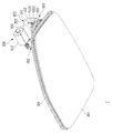
도 1 및 도 2는 본 발명의 실시예에 따른 차량의 충전을 위한 커버 개폐 장치가 도시된 사시도.
도 3은 본 발명의 실시예에 따른 차량의 충전을 위한 커버 개폐 장치가 도시된 측면도.
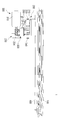
도 4 및 도 5는 본 발명의 실시예에 따른 차량의 충전을 위한 커버 개폐 장치가 도시된 분해 사시도.
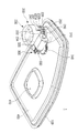
도 6은 본 발명의 실시예에 따른 제1 위치에서 제2 위치로 슬라이딩 회전된 커버가 도시된 사시도.
도 7 내지 도 11은 본 발명의 실시예에 따른 커버 가이드부가 도시된 측면도.
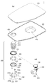
도 12 및 도 13은 본 발명의 실시예에 따른 구동부가 도시된 분해 사시도.
도 14는 본 발명의 실시예에 따른 구동부가 도시된 단면도.
도 15는 본 발명의 실시예에 따른 제1 기어의 삽입 홈이 도시된 개략도.
도 16은 본 발명의 실시예에 따른 제1 기어의 삽입 홈과 제2 기어의 삽입 돌기가 도시된 개략도.
도 17은 본 발명의 실시예에 따른 제1 기어 및 제2 기어의 중심축 방향으로 이동되는 제1 기어가 도시된 개략도.
도 18은 본 발명의 실시예에 따른 제1 기어 및 제2 기어의 중심축 방향으로 이동되는 제1 기어가 도시된 단면도.1 and 2 are perspective views showing a cover opening and closing device for charging a vehicle according to an embodiment of the present invention.
3 is a side view illustrating a cover opening and closing device for charging a vehicle according to an embodiment of the present invention;
4 and 5 are exploded perspective views showing a cover opening and closing device for charging a vehicle according to an embodiment of the present invention.
6 is a perspective view showing a cover slidably rotated from a first position to a second position according to an embodiment of the present invention;
7 to 11 are side views showing a cover guide unit according to an embodiment of the present invention.
12 and 13 are exploded perspective views showing a driving unit according to an embodiment of the present invention.
14 is a cross-sectional view showing a driving unit according to an embodiment of the present invention.
15 is a schematic view showing an insertion groove of the first gear according to an embodiment of the present invention.
16 is a schematic view showing the insertion groove of the first gear and the insertion protrusion of the second gear according to an embodiment of the present invention.
17 is a schematic view showing the first gear moving in the central axis direction of the first gear and the second gear according to an embodiment of the present invention.
18 is a cross-sectional view showing the first gear moving in the central axis direction of the first gear and the second gear according to the embodiment of the present invention.
본 발명의 이점 및 특징, 그리고 그것들을 달성하는 방법은 첨부되는 도면과 함께 상세하게 후술되어 있는 실시예들을 참조하면 명확해질 것이다. 그러나 본 발명은 이하에서 개시되는 실시예들에 한정되는 것이 아니라 서로 다른 다양한 형태로 구현될 수 있으며, 단지 본 실시예들은 본 발명의 개시가 완전하도록 하고, 본 발명이 속하는 기술분야에서 통상의 지식을 가진 자에게 발명의 범주를 완전하게 알려주기 위해 제공되는 것이며, 본 발명은 청구항의 범주에 의해 정의될 뿐이다. 명세서 전체에 걸쳐 동일 참조 부호는 동일 구성 요소를 지칭한다.Advantages and features of the present invention and methods of achieving them will become apparent with reference to the embodiments described below in detail in conjunction with the accompanying drawings. However, the present invention is not limited to the embodiments disclosed below, but may be implemented in various different forms, and only these embodiments allow the disclosure of the present invention to be complete, and common knowledge in the art to which the present invention pertains It is provided to fully inform those who have the scope of the invention, and the present invention is only defined by the scope of the claims. Like reference numerals refer to like elements throughout.
따라서, 몇몇 실시예에서, 잘 알려진 공정 단계들, 잘 알려진 구조 및 잘 알려진 기술들은 본 발명이 모호하게 해석되는 것을 피하기 위하여 구체적으로 설명되지 않는다.Accordingly, in some embodiments, well-known process steps, well-known structures, and well-known techniques have not been specifically described in order to avoid obscuring the present invention.
본 명세서에서 사용된 용어는 실시예들을 설명하기 위한 것이며 본 발명을 제한하고자 하는 것은 아니다. 본 명세서에서, 단수형은 문구에서 특별히 언급하지 않는 한 복수형도 포함한다. 명세서에서 사용되는 포함한다(comprises) 및/또는 포함하는(comprising)은 언급된 구성요소, 단계 및/또는 동작 이외의 하나 이상의 다른 구성요소, 단계 및/또는 동작의 존재 또는 추가를 배제하지 않는 의미로 사용한다. 그리고, "및/또는"은 언급된 아이템들의 각각 및 하나 이상의 모든 조합을 포함한다. The terminology used herein is for the purpose of describing the embodiments and is not intended to limit the present invention. In this specification, the singular also includes the plural unless specifically stated otherwise in the phrase. As used herein, includes and/or comprising means not excluding the presence or addition of one or more other components, steps and/or actions other than the stated components, steps and/or actions. use it as And, “and/or” includes each and every combination of one or more of the recited items.
또한, 본 명세서에서 기술하는 실시예들은 본 발명의 이상적인 예시도인 사시도, 단면도, 측면도 및/또는 개략도들을 참고하여 설명될 것이다. 따라서, 제조 기술 및/또는 허용 오차 등에 의해 예시도의 형태가 변형될 수 있다. 따라서, 본 발명의 실시예들은 도시된 특정 형태로 제한되는 것이 아니라 제조 공정에 따라 생성되는 형태의 변화도 포함하는 것이다. 또한, 본 발명에 도시된 각 도면에 있어서 각 구성 요소들은 설명의 편의를 고려하여 다소 확대 또는 축소되어 도시된 것일 수 있다.Further, the embodiments described herein will be described with reference to perspective views, cross-sectional views, side views, and/or schematic views that are ideal illustrative views of the present invention. Accordingly, the shape of the illustrative drawing may be modified due to manufacturing technology and/or tolerance. Accordingly, the embodiments of the present invention are not limited to the specific form shown, but also include changes in the form generated according to the manufacturing process. In addition, in each of the drawings shown in the present invention, each component may be enlarged or reduced to some extent in consideration of convenience of description.
이하, 본 발명의 실시예들에 의하여 차량의 충전을 위한 커버 개폐 장치를 설명하기 위한 도면들을 참고하여 본 발명에 대해 설명하도록 한다.Hereinafter, the present invention will be described with reference to the drawings for explaining a cover opening and closing device for charging a vehicle according to embodiments of the present invention.
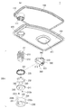
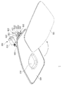
도 1 및 도 2는 본 발명의 실시예에 따른 차량의 충전을 위한 커버 개폐 장치가 도시된 사시도이고, 도 3은 본 발명의 실시예에 따른 차량의 충전을 위한 커버 개폐 장치가 도시된 측면도이며, 도 4 및 도 5는 본 발명의 실시예에 따른 차량의 충전을 위한 커버 개폐 장치가 도시된 분해 사시도이다.1 and 2 are perspective views showing a cover opening and closing device for charging a vehicle according to an embodiment of the present invention, and FIG. 3 is a side view showing a cover opening and closing device for charging a vehicle according to an embodiment of the present invention. , FIGS. 4 and 5 are exploded perspective views illustrating a cover opening and closing device for charging a vehicle according to an embodiment of the present invention.
도 1 내지 도 5를 참조하면, 본 발명의 실시예에 따른 차량의 충전을 위한 커버 개폐 장치(1)는 커버(100), 커버 가이드부(200), 및 구동부(300)를 포함할 수 있다.1 to 5 , the cover opening and
본 발명의 실시예에서 차량의 충전을 위한 커버 개폐 장치(1)는 배터리의 전원을 이용한 전기 모터의 구동을 통해 동력을 얻는 전기 차량의 배터리 충전을 위한 용도로 사용되는 경우를 예를 들어 설명하기로 하나, 이에 한정되지 않고, 본 발명의 차량의 충전을 위한 커버 개폐 장치(1)는 전기 모터나 내연 기관 엔진을 동력원으로 하는 차량의 배터리 충전을 위한 충전 포트나 연료 주입을 위한 주유구가 외부에 노출되거나 노출되지 않도록 하는 용도로 사용될 수 있다.In an embodiment of the present invention, the cover opening and
커버(100)는 배터리의 전원을 이용한 모터의 구동을 통해 동력을 얻는 전기 차량이 충전소 등에서 배터리를 충전하고자 할 때 충전 건과 전기적으로 연결되는 충전 포트가 외부에 노출되도록 하고, 이와 반대로 배터리의 미충전 시에는 충전 포트가 외부에 노출되지 않도록 하여 외부 충격이나 이물질의 유입 등으로 인한 충전 포트의 파손이나 불량이 발생되지 않도록 하는 역할을 할 수 있다.The
충전 포트는 차체에 구비되는 포트 하우징(400)의 개구부(410)를 통해 충전소의 충전 건과 전기적으로 연결 가능하게 되며, 커버(100)는 제1 위치에서 포트 하우징(400)이 가려지도록 위치하여 충전 포트가 외부에 노출되지 않도록 하고, 배터리의 충전이 필요한 경우에는 포트 하우징(400)이 외부에 드러나도록 제1 위치에서 제2 위치로 위치가 변경되어 충전 포트가 외부에 노출되도록 하게 된다.The charging port can be electrically connected to the charging gun of the charging station through the
이때, 내연 기관 엔진을 동력원으로 하는 차량은 전기 차량과 유사하게 포트 하우징(400)의 개구부(410)에 주유구가 위치하게 되어 연료의 주입이 가능하게 되며, 이 경우 포트 하우징(400)이라는 용어는 동력원의 종류에 따라 달라질 수 있다.At this time, in a vehicle using an internal combustion engine as a power source, the fuel port is located in the
전술한 도 1 내지 도 5는 포트 하우징(400)이 가려지도록 커버(100)가 제1 위치에 있는 경우의 일 예로서, 커버(100)는 슬라이딩 회전되어 제1 위치 및 제2 위치 중 어느 하나에 위치할 수 있으며, 커버(100)가 슬라이딩 회전되어 제1 위치로부터 제2 위치로 위치가 변경되는 경우 도 6과 같이 포트 하우징(400)이 노출될 수 있고, 포트 하우징(400)의 개구부(410)를 통해 충전 건을 충전 포트에 연결하여 배터리의 충전이 가능하게 되는 것이다.The above-described FIGS. 1 to 5 are an example of a case in which the
본 발명의 실시예에서 커버(100)가 슬라이딩 회전된다는 것은 커버(100) 및 포트 하우징(400)의 서로 마주보는 면이 대략 평행을 유지하면서 커버(100)가 회전된다는 것을 의미하는 것으로서, 커버(100) 및 포트 하우징(400)이 접촉 또는 비접촉된 상태에서 커버(100)가 슬라이딩 회전되는 경우가 포함될 수 있다.The sliding rotation of the
이때, 본 발명의 실시예에서 커버(100)가 슬라이딩 회전되어 위치가 변경되도록 하는 것은 배터리의 충전을 위하여 충전 포트가 외부에 노출되도록 커버(100)의 일측단이 포트 하우징(400)과 멀어지거나 가까워지도록 회전되어 위치가 변경되는 경우 차량의 바디 표면으로부터 커버(100)가 돌출되어 위치하는 끝단이 차량의 바디 표면으로부터 상대적으로 더 멀어지기 때문에 커버(100)의 위치 변경에 요구되는 공간이 증가하게 되고, 이 경우 커버(100)가 주변 차량이나 보행자 등에 부딪혀 파손될 가능성이 높아지기 때문이다.At this time, in the embodiment of the present invention, when the
커버 가이드부(200)는 커버(100) 및 포트 하우징(400)이 이격되는 간격을 조정하는 역할과 더불어 커버(100)가 제1 위치 및 제2 위치 사이에서 슬라이딩 회전되는 동안 차체와 구조적인 간섭이 발생되지 않도록 하는 역할을 할 수 있다.The
즉, 커버(100)는 배터리의 미충전 시 제1 위치에서 차량의 바디 라인에 대응되는 외곽선을 형성하여 커버(100)로 인한 이질감이 최소화되도록 위치하게 되고, 이 상태에서 커버(100)가 제1 위치에서 제2 위치로 슬라이딩 회전되는 경우 커버(100) 및 차체 사이의 구조적인 간섭으로 인하여 커버(100)의 정상적인 슬라이딩 회전이 어려울 뿐만 아니라, 커버(100)가 슬라이딩 회전이 가능하더라도 커버(100)의 슬라이딩 회전으로 인하여 차량의 바디 표면이 긁히거나 변형될 수 있게 된다.That is, the
따라서, 본 발명의 실시예에서는 커버 가이드부(200)에 의해 커버(100)가 포트 하우징(400)과 소정 간격으로 이격된 상태에서 커버(100)가 제1 위치 및 제2 위치 사이에서 슬라이딩 회전되도록 하여 커버(100) 및 차체 사이의 구조적인 간섭이 발생되지 않도록 하는 것이다.Therefore, in the embodiment of the present invention, the
다시 말해서, 배터리의 미충전 시 커버(100)는 제1 위치에서 제2 위치에 비하여 포트 하우징(400)에 가깝게 위치하여 차량의 바디 라인을 형성하게 되고, 배터리의 충전이 필요하여 커버(100)가 제1 위치에서 제2 위치로 회전되거나 배터리의 충전이 완료되어 커버(100)가 제2 위치에서 제1 위치로 회전되는 동안에는 배터리의 미충전 시에 비하여 커버(100)가 포트 하우징(400)과 상대적으로 멀리 위치하도록 이격되는 것이다.In other words, when the battery is not charged, the
커버 가이드부(200)는 리드 스크류(210), 너트 부재(220) 및 가이드 부재(230)를 포함할 수 있다.The
리드 스크류(210)는 커버(100)의 회전축(Ax1) 방향을 따라 연장되도록 형성되고, 리드 스크류(210)의 일단에 커버(100)가 연결되어 리드 스크류(210)의 회전 시 커버(100)가 회전축(Ax1)을 중심으로 리드 스크류(210)와 일체로 회전될 수 있다.The
본 발명의 실시예에서는 리드 스크류(210)의 일단이 포트 하우징(400)에 형성되는 연결 홀(420)을 통과하여 커버(100)에 형성된 수용 홈(110)에 삽입되고, 리드 스크류(210)의 일단에 형성되는 적어도 하나의 연결 돌기(211)가 수용 홈(110) 내에 형성되는 적어도 하나의 연결 홈(111)에 삽입되어 리드 스크류(210)의 회전 시 커버(100)가 일체로 회전되는 경우를 예를 들어 설명하기로 하나, 이에 한정되지 않고, 커버(100) 및 리드 스크류(210)는 나사 결합, 후크 결합, 접착제 등과 같은 다양한 방법으로 통해 일체로 회전되도록 서로 결합될 수 있다.In the embodiment of the present invention, one end of the
너트 부재(220)는 리드 스크류(210)가 통과하는 중공(221)이 형성되고, 리드 스크류(210)의 외주면과 너트 부재(220)의 중공(221) 내주면에는 각각 나사산이 형성되어 리드 스크류(210) 및 너트 부재(220)가 서로 나사 결합될 수 있게 되며, 리드 스크류(210)의 회전이 가능한 상태에서는 리드 스크류(210) 및 너트 부재(220)가 일체로 회전되고, 리드 스크류(210)의 회전이 차단된 상태에서는 너트 부재(220)의 회전 시 리드 스크류(210)가 회전축(Ax1) 방향으로 직선 이동될 수 있다.The
너트 부재(220)는 후술할 구동부(300)로부터 커버(100)를 슬라이딩 회전시키기 위한 구동력을 전달받아 회전축(Ax1)을 중심으로 회전될 수 있으며, 리드 스크류(210)는 가이드 부재(230)에 의해 회전이 차단되거나 가능하게 되어 커버(100)가 회전축(Ax1) 방향으로 이동되도록 하거나 회전축(Ax1)을 중심으로 회전되도록 할 수 있다.The
가이드 부재(230)는 리드 스크류(210)가 회전축(Ax1) 방향으로 이동 가능하게 하는 제1 가이드 홈(231) 및 리드 스크류(210)가 회전축(Ax1)을 중심으로 회전 가능하게 하는 제2 가이드 홈(232)을 포함할 수 있으며, 가이드 부재(230)는 너트 부재(220)의 회전 시 리드 스크류(210)에 구비되는 돌출 리브(241)가 제1 가이드 홈(231) 및 제2 가이드 홈(232) 중 어느 하나에 위치하도록 하여 커버(100)가 회전축(Ax1) 방향으로 이동하거나 회전축(Ax1)을 중심으로 회전되도록 할 수 있다.The
돌출 리브(241)는 리드 스크류(210)의 타단에 결합되는 결합부(240)의 외주단에 적어도 하나가 형성될 수 있으며, 돌출 리브(241)마다 제1 가이드 홈(231) 및 제2 가이드 홈(232)이 쌍으로 형성될 수 있다. At least one protruding
본 발명의 실시예에서 결합부(240)는 리드 스크류(210)의 타단이 통과하는 통과 홀(242)이 형성되고, 리드 스크류(210)의 타단에 형성되는 결합 홈(212)에 결합되는 결합 부재(243a)가 통과하는 결합 홀(243)이 형성되어 리드 스크류(210)의 타단에 결합되는 경우를 예를 들어 설명하기로 하나, 이에 한정되지 않고, 돌출 리브(241)는 리드 스크류(210)의 타단에 일체로 형성될 수도 있으며, 이 경우 결합부(240)는 생략될 수 있다.In the embodiment of the present invention, the
가이드 부재(230)는 회전축(Ax1) 방향으로 리드 스크류(210)의 타단을 수용하는 수용 공간(233)이 형성될 수 있고, 제1 가이드 홈(231) 및 제2 가이드 홈(232)은 수용 공간(233)을 형성하는 측벽(234)에 형성될 수 있다.The
제1 가이드 홈(231)은 커버(100)가 제1 위치에서 제2 위치로 회전되기 이전에 커버(100)가 포트 하우징(400)과 소정 간격으로 이격되도록 커버(100) 및 포트 하우징(400)이 이격되는 간격에 대응되는 길이를 가지도록 회전축(Ax1) 방향으로 연장되도록 형성될 수 있고, 제2 가이드 홈(232)은 제1 가이드 홈(231)에 의해 포트 하우징(400)과 소정 간격으로 이격된 커버(100)가 제1 위치 및 제2 위치 사이에서 회전될 때 커버(100)의 회전 범위에 대응되는 길이를 가지도록 회전축(Ax1)을 중심으로 하는 원주 방향으로 연장되도록 형성되며, 제2 가이드 홈(232)은 커버(100)가 포트 하우징(400)으로부터 소정 간격으로 이격된 이후 슬라이딩 회전되도록 회전축(Ax1) 방향으로 제1 가이드 홈(231)에 비하여 커버(100)에 가까운 위치에 형성될 수 있다.The
제1 가이드 홈(231)은 커버(100)에 가까운 일단에 돌출 리브(241)의 삽입 또는 이탈을 가능하게 하는 삽입구(231a)가 형성될 수 있고, 제2 가이드 홈(232)은 제1 가이드 홈(231)으로부터 이탈되는 돌출 리브(241)가 제2 가이드 홈(232)을 따라 이동 가능하도록 제1 가이드 홈(231)에 가까운 일단이 제1 가이드 홈(231)의 삽입구(231a)와 연통되도록 형성될 수 있다.The
제2 가이드 홈(232)의 양단 부근에는 돌출 리브(241)의 회전 범위를 규정하기 위한 복수의 격벽(232a, 232b)이 각각 형성될 수 있고, 이하 본 발명의 실시예에서 복수의 격벽(232a, 232b)을 각각 제1 격벽(232a) 및 제2 격벽(232b)이라 칭하기로 한다.A plurality of
이때, 복수의 격벽(232a, 232b)이 돌출 리브(241)의 회전 범위를 규정한다는 것은 리드 스크류(210)와 일체로 회전되는 커버(100)의 회전 범위를 규정한다는 것으로 이해될 수 있다.In this case, when the plurality of
제1 격벽(232a)은 제1 가이드 홈(231)의 삽입구(231a)로부터 먼 위치에 형성되어 커버(100)가 제1 위치로부터 제2 위치로 회전될 때 회전 각도를 규정하고, 제2 격벽(232b)은 제1 가이드 홈(231)의 삽입구(231a)에 가까운 위치에 형성되어 커버(100)가 제2 위치로부터 제1 위치로 회전될 때 회전 각도를 규정하는 역할을 할 수 있다.The
이때, 제2 격벽(232b)은 제1 가이드 홈(231)의 삽입구(231a)를 기준으로 제2 가이드 홈(232)의 반대측에 형성되어 제2 위치에서 제1 위치로 회전된 커버(100)가 제1 가이드 홈(231)의 삽입구(231a)를 통해 제1 가이드 홈(231)에 삽입 가능하게 된다.At this time, the
즉, 돌출 리브(241)가 제2 격벽(232b)과 가까워지는 방향으로 커버(100)가 회전되는 경우, 돌출 리브(241)가 제2 격벽(232b)에 맞닿은 이후에는 너트 부재(220)가 회전되는 경우라도 리드 스크류(210)의 회전이 차단되어 리드 스크류(210)가 커버(100)의 회전축(Ax1) 방향으로 이동하게 되고, 이 경우 돌출 리브(241)가 제1 가이드 홈(231)에 삽입되는 방향으로 이동하게 되어 커버(100) 및 포트 하우징(400) 사이의 간격이 가까워지게 되는 것이다. That is, when the
따라서, 커버(100)가 제1 위치 및 제2 위치 사이에서 슬라이딩 회전될 때 회전 범위는 제1 격벽(232a) 및 제2 격벽(232b)에 의해 규정되고, 제1 위치에서 너트 부재(220)의 회전 방향에 따라 돌출 리브(241)가 제1 가이드 홈(231)을 따라 이동되면서 커버(100)가 포트 하우징(400)과 가까워지거나 포트 하우징(400)과 멀어지도록 회전축(Ax1) 방향을 따라 이동될 수 있는 것이다.Accordingly, when the
너트 부재(220)는 구동부(300)로부터 전달되는 구동력에 따라 회전축(Ax1)을 중심으로 양방향 중 어느 하나의 방향으로 회전되어 리드 스크류(210)가 회전축(Ax1) 방향으로 이동되거나 회전축(Ax1)을 중심으로 회전되도록 할 수 있다.The
예를 들어, 배터리의 미충전 시 돌출 리브(241)는 도 7과 같이 제1 가이드 홈(231) 내에 위치하게 되고, 배터리의 충전이 필요하여 너트 부재(220)가 구동부(300)로부터 전달되는 구동력에 의해 제1 방향으로 회전되는 경우 리드 스크류(210)는 제1 가이드 홈(231) 내에 위치하는 돌출 리브(241)로 인하여 회전이 차단된 상태이기 때문에 돌출 리브(241)가 제1 가이드 홈(231)의 삽입구(231a)를 향하도록 리드 스크류(210)가 직선 이동하게 되어 도 8과 같이 커버(100)가 회전축(Ax1) 방향으로 직선 이동되어 포트 하우징(400)과 이격되어 돌출 리브(241)가 삽입구(231a)를 통해 제1 가이드 홈(231)으로부터 이탈될 수 있다.For example, when the battery is not charged, the protruding
돌출 리브(241)가 삽입구(231a)를 통해 제1 가이드 홈(231)으로부터 이탈되는 경우, 리드 스크류(210)가 너트 부재(220)와 함께 회전 가능한 상태가 되어 도 9와 같이 돌출 리브(241)가 제1 격벽(232a)에 가까워지도록 회전하여 전술한 도 6과 같이 커버(100)가 제1 위치에서 제2 위치로 회전될 수 있게 되는 것이다.When the protruding
이와 반대로, 배터리의 충전이 완료된 경우에는 구동부(300)의 구동력에 의해 너트 부재(220)가 제2 방향으로 회전하여 커버(100)가 제2 위치에서 제1 위치로 회전하게 되고, 이 경우 돌출 리브(241)가 도 10과 같이 전술한 도 9와 반대 방향으로 회전하여 제2 격벽(232b)과 가까워지도록 회전하게 되며, 제2 격벽(232b)에 돌출 리브(241)가 맞닿은 상태에서 너트 부재(220)가 제2 방향으로 회전되는 경우라도 리드 스크류(210)의 회전이 차단되어 도 11과 같이 제1 가이드 홈(231)의 삽입구(231a)를 통해 제1 가이드 홈(231a)에 삽입되어 커버(100)가 포트 하우징(400)과 가까워지도록 리드 스크류(210)가 직선 이동하게 되는 것이다.Conversely, when the battery is fully charged, the
전술한 바와 같이, 본 발명의 차량의 충전을 위한 커버 개폐 장치(1)는 커버(100)가 포트 하우징(400)가 이격되는 간격을 조정하기 위한 구조와 커버(100)를 슬라이딩 회전시키기 위한 구조를 별도로 형성하지 않고, 가이드 부재(230)에 의해 커버(100)의 직선 이동과 슬라이딩 회전이 가능하기 때문에 간단한 구성을 통해 커버(100)가 개폐될 수 있게 된다.As described above, the cover opening/
한편, 너트 부재(220) 및 결합부(240) 사이에는 코일 스프링 등과 같은 탄성부(250)가 위치할 수 있으며, 너트 부재(220)는 탄성부(250)에 의해 탄성 지지될 수 있게 되어 너트 부재(220)의 하중 등으로 인하여 너트 부재(220)가 정위치로부터 이탈, 즉 하측으로 이동되는 것이 방지될 수 있게 된다.Meanwhile, an
전술한 실시예에서는 돌출 리브(241)가 리드 스크류(210)에 구비되고, 너트 부재(220)의 회전 시 리드 스크류(210)가 커버(100)의 회전축(Ax) 방향으로 이동하거나 커버(100)의 회전축(Ax)을 중심으로 회전되는 경우를 예를 들어 설명하고 있으나, 이에 한정되지 않고, 돌출 리브(241)가 너트 부재(220)에 구비되는 경우에는 리드 스크류(210)의 회전 시 너트 부재(220)가 커버(100)의 회전축(Ax) 방향으로 이동하거나 커버(100)의 회전축(Ax)을 중심으로 회전될 수도 있다.In the above-described embodiment, the protruding
즉, 리드 스크류(210)가 커버(100)와 일체로 회전되도록 결합되고, 돌출 리브(241)가 리드 스크류(210)에 구비되는 경우에는 구동부(300)로부터 전달되는 구동력에 의해 너트 부재(220)가 회전될 때 제1 가이드 홈(231) 및 제2 가이드 홈(232) 중 돌출 리브(241)가 위치하는 가이드 홈에 따라 리드 스크류(210)가 커버(100)의 회전축(Ax) 방향으로 이동하거나 커버(100)의 회전축(Ax)을 중심으로 회전될 수 있게 되고, 이와 달리 너트 부재(220)가 커버(100)와 일체로 회전되도록 회전되도록 결합디고, 돌출 리브(241)가 너트 부재(220)에 구비되는 경우에는 구동부(300)로부터 전달되는 구동력에 의해 리드 스크류(210)가 회전될 때 제1 가이드 홈(231) 및 제2 가이드 홈(232) 중 돌출 리브(241)가 위치하는 가이드 홈에 따라 너트 부재(220)가 커버(100)의 회전축(Ax) 방향으로 이동하거나 커버(100)의 회전축(Ax)을 중심으로 회전될 수 있는 것이다.That is, when the
구동부(300)는 커버(100)의 위치를 변경하기 위한 구동력을 제공하는 역할을 할 수 있다.The driving
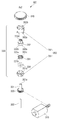
도 12 및 도 13은 본 발명의 실시예에 따른 구동부가 도시된 분해 사시도이고, 도 14는 본 발명의 실시예에 따른 구동부가 도시된 단면도이다.12 and 13 are exploded perspective views illustrating a driving unit according to an embodiment of the present invention, and FIG. 14 is a cross-sectional view illustrating a driving unit according to an embodiment of the present invention.
도 12 내지 도 14를 참조하면, 본 발명의 실시예에 따른 구동부(300)는 액추에이터(310), 전달 기어(320), 구동력 전달부(330), 및 구동 기어(340)를 포함할 수 있다. 12 to 14 , the driving
액추에이터(310)는 커버(100)의 위치 변경을 위한 구동력이 발생될 수 있으며, 너트 부재(220)는 액추에이터(310)의 구동력 발생 방향에 따라 커버(100)의 회전축(Ax1)을 중심으로 양방향 중 어느 하나의 방향으로 회전될 수 있다.The
액추에이터(310)로부터 발생되는 구동력은 전달 기어(320)를 통해 구동력 전달부(330)로 전달될 수 있고, 구동 기어(340)는 구동력 전달부(330)를 통해 전달되는 구동력을 너트 부재(220)로 전달하여 너트 부재(220)가 회전되도록 하게 된다.The driving force generated from the
본 발명의 실시예에서는 액추에이터(310)의 회전축에 연결되는 웜 기어에 의해 액추에이터(310)의 구동력이 전달 기어(320)로 전달되는 경우를 예를 들어 설명하기로 하나, 이에 한정되지 않고, 전달 기어(320)가 액추에이터(310)의 회전축에 직접 연결되는 경우 웜 기어는 생략될 수 있다.In the embodiment of the present invention, a case in which the driving force of the
이때, 본 발명의 실시예에서는 구동 기어(340)에 의해 너트 부재(220)로 구동력이 전달되는 경우를 예를 들어 설명하기로 하나, 이에 한정되지 않고, 너트 부재(220)가 커버(100)와 일체로 회전되도록 회전되고, 너트 부재(220)에 구비되는 돌출 리브(241)의 위치에 따라 너트 부재(220)가 커버(100)의 회전축(Ax) 방향으로 이동되거나 커버(100)의 회전축(Ax)을 중심으로 회전되는 경우에는 구동 기어(340)에 의해 리드 스크류(210)로 구동력이 전달될 수도 있다.At this time, in the embodiment of the present invention, a case in which the driving force is transmitted to the
구동력 전달부(330)는 전달 기어(320)로부터 구동력을 전달받는 제1 기어(331) 및 제1 기어(331)로 전달되는 구동력을 구동 기어(340)로 전달하는 제2 기어(332)를 포함할 수 있으며, 제1 기어(331) 및 제2 기어(332)는 동일한 중심축(Ax2)을 중심으로 회전되도록 배치될 수 있다.The driving
본 발명의 실시예에서는 커버(100)의 회전축(Ax1)과 제1 기어(331) 및 제2 기어(332)의 중심축(Ax2)이 서로 평행하게 위치하는 경우를 예를 들어 설명하고 있으나, 이에 한정되지 않고, 구동력 전달부(330)와 구동 기어(340) 사이의 구동력 전달 구조에 따라 커버(100)의 회전축(Ax1)과 제1 기어(331) 및 제2 기어(332)의 중심축(Ax2)는 서로 평행하지 않을 수도 있다.In the embodiment of the present invention, the case where the rotation axis Ax1 of the
또한, 본 발명의 실시예에서 제1 기어(331) 및 제2 기어(332)는 중심축(Ax2) 방향을 따라 서로 결합되는 제1 케이스(351) 및 제2 케이스(352)로 구성되는 하우징(350) 내에 수용되는 경우를 예를 들어 설명하기로 하며, 제1 케이스(351) 및 제2 케이스(352) 중 커버(100)에 가까운 제2 케이스(352)에 형성된 적어도 하나의 결합 돌기(352a)가 제1 케이스(351)의 외측면에 걸리게 되어 서로 결합될 수 있으나, 이에 한정되지 않고, 제1 케이스(351) 및 제2 케이스(352)는 나사 결합, 후크 결합, 접착제 등과 같은 다양한 방법에 의해 결합될 수 있다.In addition, in the embodiment of the present invention, the
제1 기어(331) 및 제2 기어(332)는 각각 서로 마주보는 면에 중심축(Ax2)을 중심으로 하는 원주 방향으로 삽입 돌기(331a, 332a)와 삽입 홈(331b, 332b)가 교대로 형성될 수 있다.The
따라서, 제1 기어(331)의 삽입 돌기(331a)가 제2 기어(332)의 삽입 홈(332b)에 삽입되고, 제1 기어(331)의 삽입 홈(331b)에 제2 기어(332)의 삽입 돌기(332a)가 삽입되는 경우, 제1 기어(331) 및 제2 기어(332) 중 어느 하나로 전달된 구동력이 다른 하나로 전달되어 구동력의 전달이 가능하게 된다.Accordingly, the
제1 기어(331)는 전달 기어(320)의 중심축 역할을 하는 샤프트(321)의 단부가 삽입되는 중공(331c)이 형성될 수 있으며, 중공(331c)은 중심축(Ax2)에 수직한 방향으로 샤프트(321)의 단면 형상에 대응되는 형상을 가질 수 있다.The
본 발명의 실시예에서 샤프트(321)는 곡선, 직선, 또는 이들이 조합된 비원형의 단면 형상을 가지는 경우를 예를 들어 설명하기로 하며, 이는 전달 기어(320)의 회전 시 제1 기어(331)가 일체로 회전되도록 하기 위한 것이다.In the embodiment of the present invention, a case in which the
즉, 샤프트(321)의 단면 형상이 원형인 경우에는 샤프트(321)가 제1 기어(331)의 중공(331c) 내에서 헛돌게 되어 전달 기어(320)로부터 제1 기어(331)로 구동력이 제2 기어(332)에 정상적으로 전달되지 못할 가능성이 있기 때문에 본 발명의 실시예에서는 샤프트(321)의 단면이 비원형 형상을 가지도록 하여 전달 기어(320)로부터 제1 기어(331)로 구동력이 전달되도록 하는 것이다.That is, when the cross-sectional shape of the
전달 기어(320)의 샤프트(321)의 단부는 제1 케이스(351) 및 제2 케이스(352) 중 구동 기어(340)로부터 멀리 위치하는 제1 케이스(351)에 형성되는 관통 홀(351a)을 관통하여 제1 기어(331)의 중공(331c)에 삽입될 수 있다.The end of the
또한, 전달 기어(320)는 일단이 제1 기어(331)를 마주보는 제2 기어(332)의 대향면에 형성되는 고정 홈(332c)에 삽입되도록 위치하여 제2 기어(332)가 정위치를 유지하면서 회전되도록 하는 회전 샤프트(322)가 통과되는 통과 홀(321a)이 전달 기어(320)의 샤프트(321)에 중심축(Ax2) 방향으로 양단이 연통되도록 형성될 수 있다.In addition, the
제2 기어(332)는 구동 기어(340)의 샤프트(341)의 단부가 삽입되어 제2 기어(332) 및 구동 기어(340)가 서로 일체로 회전되도록 하는 고정 홈(332d)이 형성될 수 있고, 구동 기어(340)의 샤프트(341)는 제2 케이스(352)에 형성되는 관통 홀(352b)를 통해 제2 기어(332)의 고정 홈(332d)에 삽입되어 고정될 수 있다.The
한편, 제1 기어(331) 및 제1 케이스(351) 사이에는 탄성 부재(334)가 위치할 수 있으며, 이는 액추에이터(310)의 고장이나 불량 등이 발생하여 액추에이터(310)가 동작하지 않는 상태에서도 외부에서 커버(100)에 힘을 가하여 커버(100)를 제1 위치 및 제2 위치 사이에서 슬라이딩 회전시킬 수 있도록 하기 위한 것이다.On the other hand, an
본 발명의 실시예에서는 탄성 부재(334)가 제1 기어(331) 및 제1 케이스(351) 사이에 위치하는 경우를 예를 들어 설명하고 있으나, 이에 한정되지 않고, 탄성 부재(334)는 제1 기어(331)가 중심축(Ax2) 방향으로 이동 가능하게 제1 기어(331)를 탄성 지지할 수 있는 제1 기어(331) 및 하우징(350)의 내측 일면 사이에 위치하는 것으로 이해될 수 있다.In the embodiment of the present invention, the case in which the
즉, 액추에이터(310)의 고장이나 불량 등으로 인하여 액추에이터(310)가 동작하지 않는 상태에서 외부에서 커버(100)에 힘을 가하는 경우, 제1 기어(331)는 액추에이터(310)가 동작되지 않아 회전되지 않고 정지된 상태를 유지하게 되나, 제2 기어(332)는 외부로부터 커버(100)에 가해지는 힘을 구동 기어(340)를 통해 전달받게 되고, 이 경우 제2 기어(332)의 삽입 돌기(332a)가 제1 기어(331)의 삽입 홈(331b)으로부터 이탈되어 인접한 다른 삽입 홈에 삽입되는 과정을 통해 외부 힘에 의해 커버(100)가 회전 가능하게 된다.That is, when a force is applied to the
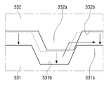
이때, 제1 기어(331)의 삽입 홈(331b)은 도 15와 같이 저면(331d) 및 제1 기어(331)의 회전 방향으로 저면(331d)의 양측에 각각 위치하는 복수의 측벽(331e, 331f)을 포함할 수 있고, 복수의 측벽(331e, 331f) 각각이 저면(331d)과 이루는 각도(θ)는 적어도 90도 이상을 가지도록 형성될 수 있다.At this time, the
복수의 측벽(331e, 331f) 각각이 저면(331d)과 이루는 각도(θ)가 적어도 90도 이상인 것은 제1 기어(331)가 회전되지 않도록 고정된 상태에서 외부에서 커버(100)에 가해지는 힘이 제2 기어(332)에 전달되는 경우 제1 기어(331)가 탄성 부재(334)를 압축시키는 방향으로 이동될 수 있도록 하기 위함이다.When the angle θ between the plurality of sidewalls 331e and 331f formed with the
즉, 제1 기어(331)의 삽입 홈(331b)에 제2 기어(332)의 삽입 돌기(332a)가 삽입되어 위치하는 경우, 도 16과 같이 제1 기어(331)의 삽입 홈(331b)의 측벽(331e, 331f)과 마주보는 삽입 돌기(332a)의 대향면은 대략 평행하도록 형성되고, 제1 기어(331)가 고정된 상태라도 제2 기어(332)를 회전시키려는 힘에 의해 제1 기어(331)가 탄성 부재(334)를 압축시키는 방향으로 힘을 받게 되며, 이 경우 도 17 및 도 18과 같이 측벽(331e, 331f)이 가지는 경사각으로 인하여 제1 기어(331)가 탄성 부재(334)를 압축시키는 방향으로 이동되어 제2 기어(332)의 삽입 돌기(332a)가 인접한 다른 삽입 홈으로 이동하여 위치하는 것이 가능하게 되는 것이다.That is, when the
전술한 도 17 및 도 18의 과정이 반복적으로 이루어지는 경우 액추에이터(310)의 고장이나 불량 등으로 인하여 액추에이터(310)가 동작하지 않는 상태에서도 외부에서 커버(100)에 힘을 가하여 커버(100)를 제1 위치 및 제2 위치 사이에서 슬라이딩 회전시키는 것이 가능하게 되는 것이다.When the process of FIGS. 17 and 18 described above is repeatedly performed, even in a state in which the
이때, 전술한 도 17에서 점선은 제1 기어(331)가 탄성 부재(334)를 압축시키는 방향으로 이동되기 이전의 위치를 나타내는 것으로서, 제2 기어(332)는 중심축(Ax2) 방향으로 위치가 일정하게 유지된 상태에서 회전되는 반면, 제1 기어(331)는 중심축(Ax1) 방향으로 탄성 부재(334)가 압축되거나 이완되도록 하는 방향으로 이동되면서 제2 기어(332)의 회전이 가능하게 되는 것이다.At this time, the dotted line in FIG. 17 above indicates the position before the
따라서, 커버(100)가 배터리의 충전을 위하여 제2 위치로 회전된 상태에서 액추에이터(310)의 고장이나 불량 등으로 인하여 동작하지 않는 상황에서도 커버(100)에 힘을 가하여 커버(100)를 제2 위치에서 제1 위치로 회전하여 충전 포트가 외부에 노출되지 않도록 할 수 있게 되는 것이다.Therefore, even in a situation in which the
전술한 도 15에서는 제1 기어(331)의 삽입 홈(331b)을 예를 들어 설명하고 있으나, 이에 한정되지 않고, 제2 기어(332)의 삽입 홈(332b)도 제1 기어(331)와 마찬가지로 저면과 복수의 측벽이 이루는 각도가 적어도 90도 이상으로 형성될 수 있다.In FIG. 15 described above, the
본 발명의 실시예에서는 제1 기어(331)의 삽입 홈(331b) 및 제2 기어(332)의 삽입 홈(332b) 각각의 저면과 측벽 사이의 각도가 적어도 90도 이상인 경우를 예를 들어 설명하고 있으나, 이는 본 발명의 이해를 돕기 위한 일 예에 불과한 것으로서, 이에 한정되지 않고, 삽입 홈에 삽입되는 삽입 돌기의 대향면, 즉 삽입 홈의 저면과 측벽에 각각 대향되는 면 사이의 각도가 적어도 90도 이상을 가지도록 형성될 수도 있다.In the embodiment of the present invention, the angle between the bottom surface and the sidewall of each of the
전술한 바와 같이 본 발명의 차량의 충전을 위한 커버 개폐 장치(1)는 커버(100)의 슬라이딩 회전을 통해 커버(100)의 개폐 시 요구되는 공간이 줄어들 수 있게 되고, 커버(100)의 슬라이딩 회전 시 포트 하우징(400)과 소정 간격으로 이격되어 회전되기 때문에 커버(100)의 슬라이딩 회전 시 구조적인 간섭이 발생되는 것이 방지될 수 있다.As described above, in the cover opening and
또한, 구동부(300)의 고장 또는 불량으로 인하여 커버(100)의 슬라이딩 회전을 위한 구동력이 발생되지 않는 상황에서도 커버(100)에 외부 힘을 가하여 커버(100)를 슬라이딩 회전시킬 수 있기 때문에 고장 또는 불량 발생에 대하여 신속한 대처가 가능하게 된다.In addition, even in a situation in which a driving force for sliding rotation of the
본 발명이 속하는 기술분야의 통상의 지식을 가진 자는 본 발명이 그 기술적 사상이나 필수적인 특징을 변경하지 않고서 다른 구체적인 형태로 실시될 수 있다는 것을 이해할 수 있을 것이다. 그러므로 이상에서 기술한 실시예들은 모든 면에서 예시적인 것이며 한정적이 아닌 것으로 이해해야만 한다. 본 발명의 범위는 상기 상세한 설명보다는 후술하는 특허청구의 범위에 의하여 나타내어지며, 특허청구의 범위의 의미 및 범위 그리고 그 균등 개념으로부터 도출되는 모든 변경 또는 변형된 형태가 본 발명의 범위에 포함되는 것으로 해석되어야 한다.Those of ordinary skill in the art to which the present invention pertains will understand that the present invention may be embodied in other specific forms without changing the technical spirit or essential features thereof. Therefore, it should be understood that the embodiments described above are illustrative in all respects and not restrictive. The scope of the present invention is indicated by the following claims rather than the above detailed description, and all changes or modifications derived from the meaning and scope of the claims and their equivalent concepts are included in the scope of the present invention. should be interpreted
100: 커버
110: 수용 홈
111: 연결 홈
200: 커버 가이드부
210: 리드 스크류
211: 연결 돌기
212: 결합 홈
220: 너트 부재
221: 중공
230: 가이드 부재
231: 제1 가이드 홈
231a: 삽입구
232: 제2 가이드 홈
232a, 232b: 격벽
233: 수용 공간
234: 측벽
240: 결합부
241: 돌출 리브
242: 통과 홀
243: 결합 홀
300: 구동부
310: 액추에이터
320: 전달 기어
321: 샤프트
321a: 통과 홀
322: 회전 샤프트
330: 구동력 전달부
331: 제1 기어
331a: 삽입 돌기
331b: 삽입 홈
331c: 중공
332: 제2 기어
332a: 삽입 돌기
332b: 삽입 홈
332c: 고정 홈
332d: 고정 홈
340: 구동 기어
341: 샤프트
350: 하우징
351: 제1 케이스
351a: 관통 홀
352: 제2 케이스
352a: 결합 돌기
352b: 관통 홀100: cover 110: receiving groove
111: connection groove 200: cover guide part
210: lead screw 211: connecting projection
212: coupling groove 220: nut member
221: hollow 230: guide member
231:
232:
233: receiving space 234: side wall
240: coupling portion 241: protruding ribs
242: through hole 243: coupling hole
300: driving unit 310: actuator
320: transmission gear 321: shaft
321a: through hole 322: rotating shaft
330: driving force transmission unit 331: first gear
331a:
331c: hollow 332: second gear
332a:
332c: fixing
340: drive gear 341: shaft
350: housing 351: first case
351a: through hole 352: second case
352a: engaging
Claims (18)
상기 커버가 상기 포트 하우징과 소정 간격으로 이격되어 슬라이딩 회전되도록 하는 커버 가이드부를 포함하며,
상기 커버 가이드부는,
리드 스크류;
상기 리드 스크류와 나사 결합되고, 상기 커버의 회전 시 상기 리드 스크류와 일체로 회전되는 너트 부재; 및
상기 리드 스크류 및 상기 너트 부재 중 어느 하나에 구비되는 돌출 리브의 이동을 안내하는 복수의 가이드 홈이 형성되는 가이드 부재를 포함하고,
상기 복수의 가이드 홈은,
상기 커버의 회전축 방향으로 연장되도록 형성되어 상기 돌출 리브가 상기 커버의 회전축 방향으로 이동 가능하게 하는 제1 가이드 홈; 및
상기 커버의 회전 방향으로 연장되도록 형성되어 상기 돌출 리브가 상기 커버의 회전 방향으로 이동 가능하게 하는 제2 가이드 홈을 포함하는 차량의 충전을 위한 커버 개폐 장치.a cover that slides and rotates on the port housing provided with a charging port for charging the battery; and
and a cover guide part for sliding and rotating the cover at a predetermined distance from the port housing,
The cover guide part,
lead screw;
a nut member screw-coupled to the lead screw and integrally rotated with the lead screw when the cover rotates; and
and a guide member in which a plurality of guide grooves for guiding the movement of the protruding rib provided in any one of the lead screw and the nut member are formed,
The plurality of guide grooves,
a first guide groove formed to extend in the direction of the rotation axis of the cover so that the protruding rib is movable in the direction of the rotation axis of the cover; and
and a second guide groove formed to extend in the rotational direction of the cover to allow the protruding ribs to move in the rotational direction of the cover.
상기 커버는,
상기 리드 스크류 및 상기 너트 부재 중 어느 하나와 일체로 회전되도록 결합되는 차량의 충전을 위한 커버 개폐 장치.The method of claim 1,
The cover is
A cover opening and closing device for charging a vehicle coupled to rotate integrally with any one of the lead screw and the nut member.
상기 제2 가이드 홈은,
상기 커버의 회전축 방향으로 상기 제1 가이드 홈에 비하여 상기 커버에 가까운 위치에 형성되는 차량의 충전을 위한 커버 개폐 장치.The method of claim 1,
The second guide groove,
A cover opening and closing device for charging a vehicle that is formed in a position closer to the cover than the first guide groove in the direction of the rotation axis of the cover.
상기 제1 가이드 홈은,
상기 커버에 가까운 일단에 상기 돌출 리브의 삽입 또는 이탈을 위한 삽입구가 형성되며,
상기 제2 가이드 홈은,
상기 제1 가이드 홈에 가까운 일단이 상기 삽입구와 연통되도록 형성되는 차량의 충전을 위한 커버 개폐 장치.The method of claim 1,
The first guide groove,
An insertion hole for insertion or separation of the protruding rib is formed at one end close to the cover,
The second guide groove,
A cover opening and closing device for charging a vehicle in which one end close to the first guide groove is formed to communicate with the insertion hole.
상기 리드 스크류 및 상기 너트 부재 중 어느 하나는,
상기 돌출 리브가 상기 제1 가이드 홈에 위치한 경우, 상기 리드 스크류 및 상기 너트 부재 중 다른 하나의 회전 시 상기 커버의 회전축 방향으로 직선 이동되어 상기 포트 하우징 및 상기 커버 사이의 간격이 조정되도록 하는 차량의 충전을 위한 커버 개폐 장치.The method of claim 1,
Any one of the lead screw and the nut member,
When the protruding rib is located in the first guide groove, when the other one of the lead screw and the nut member is rotated, it is linearly moved in the direction of the rotation axis of the cover to adjust the distance between the port housing and the cover. cover opening and closing device for
상기 리드 스크류 및 상기 너트 부재 중 어느 하나는,
상기 돌출 리브가 상기 제2 가이드 홈에 위치된 경우, 상기 리드 스크류 및 상기 너트 부재 중 다른 하나의 회전 시 상기 커버의 회전축을 중심으로 회전하여 상기 커버가 슬라이딩 회전되도록 하는 차량의 충전을 위한 커버 개폐 장치.The method of claim 1,
Any one of the lead screw and the nut member,
When the protruding rib is positioned in the second guide groove, a cover opening and closing device for charging a vehicle that rotates about a rotation axis of the cover when the other one of the lead screw and the nut member rotates so that the cover slides and rotates .
상기 커버는,
제1 위치에서 상기 제1 가이드 홈에 의해 상기 포트 하우징과 멀어지도록 이동된 이후 상기 제2 가이드 홈에 의해 제2 위치로 회전되고,
상기 제2 가이드 홈에 의해 상기 제2 위치에서 상기 제1 위치로 회전된 이후 상기 제1 가이드 홈에 의해 상기 포트 하우징과 가까워지도록 이동되는 차량의 충전을 위한 커버 개폐 장치.The method of claim 1,
The cover is
After being moved away from the port housing by the first guide groove in the first position, it is rotated to the second position by the second guide groove,
A cover opening and closing device for charging a vehicle that is moved from the second position to the first position by the second guide groove to move closer to the port housing by the first guide groove.
상기 제2 가이드 홈의 양단 부근에 각각 형성되는 복수의 격벽을 더 포함하며,
상기 커버의 회전 시 상기 돌출 리브가 상기 복수의 격벽 중 어느 하나와 맞닿게 되어 상기 커버의 회전 범위가 규정되는 차량의 충전을 위한 커버 개폐 장치.The method of claim 1,
Further comprising a plurality of partition walls respectively formed near both ends of the second guide groove,
A cover opening and closing device for charging a vehicle in which the protruding rib comes into contact with any one of the plurality of partition walls when the cover is rotated to define a rotation range of the cover.
상기 복수의 격벽 중 상기 제1 가이드 홈에 가까운 위치에 형성되는 격벽은,
상기 제2 가이드 홈을 따라 이동하는 상기 돌출 리브가 상기 제1 가이드 홈에 삽입 가능하도록 상기 제1 가이드 홈을 기준으로 상기 제2 가이드 홈의 반대측에 형성되는 차량의 충전을 위한 커버 개폐 장치.9. The method of claim 8,
Among the plurality of partition walls, the partition wall is formed at a position close to the first guide groove,
A cover opening and closing device for charging a vehicle that is formed on an opposite side of the second guide groove with respect to the first guide groove so that the protruding rib moving along the second guide groove can be inserted into the first guide groove.
상기 커버의 슬라이딩 회전을 위한 구동력이 발생되는 구동부를 더 포함하며,
상기 구동부는,
액추에이터;
상기 리드 스크류 및 너트 부재 중 어느 하나로 상기 액추에이터의 구동력을 전달하는 구동 기어; 및
상기 액추에이터의 구동력을 상기 구동 기어로 전달하는 구동력 전달부를 포함하는 차량의 충전을 위한 커버 개폐 장치.The method of claim 1,
Further comprising a driving unit for generating a driving force for sliding rotation of the cover,
The driving unit,
actuator;
a driving gear for transmitting a driving force of the actuator to any one of the lead screw and the nut member; and
A cover opening and closing device for charging a vehicle including a driving force transmitting unit for transmitting the driving force of the actuator to the driving gear.
상기 구동력 전달부는,
상기 액추에이터의 구동력에 의해 회전되는 제1 기어; 및
상기 제1 기어와 동일한 중심축을 중심으로 회전되고, 상기 제1 기어로부터 전달받은 구동력을 상기 구동 기어로 전달하는 제2 기어를 포함하는 차량의 충전을 위한 커버 개폐 장치.11. The method of claim 10,
The driving force transmission unit,
a first gear rotated by the driving force of the actuator; and
and a second gear that rotates about the same central axis as the first gear and transmits the driving force transmitted from the first gear to the driving gear.
상기 액추에이터의 구동력을 상기 제1 기어로 전달되도록 상기 중심축을 중심으로 회전되는 전달 기어를 더 포함하며,
상기 전달 기어는,
단부가 상기 제1 기어의 중공에 삽입되는 샤프트를 포함하는 차량의 충전을 위한 커버 개폐 장치.12. The method of claim 11,
Further comprising a transmission gear rotated about the central axis so as to transmit the driving force of the actuator to the first gear,
The transmission gear is
A cover opening and closing device for charging a vehicle including a shaft having an end inserted into the hollow of the first gear.
상기 전달 기어의 샤프트는,
비원형의 단면 형상을 가지는 차량의 충전을 위한 커버 개폐 장치.13. The method of claim 12,
The shaft of the transmission gear,
A cover opening and closing device for charging a vehicle having a non-circular cross-sectional shape.
상기 제1 기어 및 상기 제2 기어 각각은,
서로 마주보는 면에 상기 중심축을 중심으로 하는 원주 방향으로 삽입 돌기 및 삽입 홈이 교대로 형성되는 차량의 충전을 위한 커버 개폐 장치.12. The method of claim 11,
Each of the first gear and the second gear,
A cover opening and closing device for charging a vehicle in which insertion protrusions and insertion grooves are alternately formed on surfaces facing each other in a circumferential direction about the central axis.
상기 제1 기어 및 상기 제2 기어 중 어느 하나의 삽입 홈에는, 다른 하나의 삽입 돌기가 삽입되어 위치하게 되며,
상기 삽입 홈은,
저면; 및
상기 중심축을 중심으로 하는 원주 방향으로 상기 저면의 양측에 각각 형성되는 복수의 측벽을 포함하는 차량의 충전을 위한 커버 개폐 장치.15. The method of claim 14,
In any one of the insertion groove of the first gear and the second gear, the other insertion protrusion is inserted and positioned,
The insertion groove is
bottom; and
A cover opening and closing device for charging a vehicle including a plurality of sidewalls respectively formed on both sides of the bottom in a circumferential direction about the central axis.
상기 저면 및 상기 측벽 사이의 각도는,
적어도 90도 이상인 차량의 충전을 위한 커버 개폐 장치.16. The method of claim 15,
The angle between the bottom surface and the side wall is,
Cover opening and closing device for charging a vehicle at least 90 degrees or more.
상기 구동력 전달부는,
상기 제1 기어 및 상기 제2 기어가 수용되는 하우징을 더 포함하며,
상기 제1 기어 및 상기 하우징의 내측 일면 사이에는 상기 제1 기어가 상기 중심축 방향으로 이동 가능하도록 상기 제1 기어를 탄성 지지하는 탄성 부재가 위치하는 차량의 충전을 위한 커버 개폐 장치.15. The method of claim 14,
The driving force transmission unit,
Further comprising a housing in which the first gear and the second gear are accommodated,
An elastic member for elastically supporting the first gear is positioned between the first gear and an inner surface of the housing so that the first gear is movable in the central axis direction.
상기 구동력이 발생되지 않는 상태에서 상기 커버에 가해지는 외부 힘은 상기 구동 기어를 통해 상기 제2 기어에 전달되고,
상기 제2 기어로 전달되는 외부 힘에 의해 상기 제1 기어가 상기 탄성 부재를 압축시키는 방향으로 이동되는 경우, 상기 제1 기어 및 상기 제2 기어 중 어느 하나의 삽입 돌기가 다른 하나의 삽입 홈으로부터 이탈되어 인접한 다른 삽입 홈에 삽입되는 과정을 통해 상기 제2 기어가 회전되어 상기 커버가 회전되는 차량의 충전을 위한 커버 개폐 장치.
18. The method of claim 17,
An external force applied to the cover in a state in which the driving force is not generated is transmitted to the second gear through the driving gear,
When the first gear is moved in a direction in which the elastic member is compressed by an external force transmitted to the second gear, the insertion protrusion of any one of the first gear and the second gear is moved from the insertion groove of the other. A cover opening and closing device for charging a vehicle in which the second gear is rotated and the cover is rotated through a process of being separated and inserted into another adjacent insertion groove.
Priority Applications (2)
| Application Number | Priority Date | Filing Date | Title |
|---|---|---|---|
| KR1020200078036A KR20220000278A (en) | 2020-06-25 | 2020-06-25 | Cover opening and closing apparatus for charging |
| CN202110576477.4A CN113846932A (en) | 2020-06-25 | 2021-05-26 | Cover opening and closing device for charging of vehicle |
Applications Claiming Priority (1)
| Application Number | Priority Date | Filing Date | Title |
|---|---|---|---|
| KR1020200078036A KR20220000278A (en) | 2020-06-25 | 2020-06-25 | Cover opening and closing apparatus for charging |
Publications (1)
| Publication Number | Publication Date |
|---|---|
| KR20220000278A true KR20220000278A (en) | 2022-01-03 |
Family
ID=78973071
Family Applications (1)
| Application Number | Title | Priority Date | Filing Date |
|---|---|---|---|
| KR1020200078036A Withdrawn KR20220000278A (en) | 2020-06-25 | 2020-06-25 | Cover opening and closing apparatus for charging |
Country Status (2)
| Country | Link |
|---|---|
| KR (1) | KR20220000278A (en) |
| CN (1) | CN113846932A (en) |
Cited By (1)
| Publication number | Priority date | Publication date | Assignee | Title |
|---|---|---|---|---|
| DE102024203541A1 (en) * | 2024-04-17 | 2025-10-23 | Magna Mirrors Holding Gmbh | Tank or loading flap arrangement and method for operating a tank or loading flap arrangement |
Citations (1)
| Publication number | Priority date | Publication date | Assignee | Title |
|---|---|---|---|---|
| KR20190072075A (en) | 2017-12-15 | 2019-06-25 | 자동차부품연구원 | Charge connector for electric vehicle |
Family Cites Families (6)
| Publication number | Priority date | Publication date | Assignee | Title |
|---|---|---|---|---|
| US6508501B1 (en) * | 2001-08-21 | 2003-01-21 | Adac Plastics Inc. | Fuel filler door assembly |
| JP2006347277A (en) * | 2005-06-14 | 2006-12-28 | Asmo Co Ltd | Sun visor device for vehicle |
| DE102006061218A1 (en) * | 2006-12-20 | 2008-06-26 | GM Global Technology Operations, Inc., Detroit | Tank flap module |
| JP2009292432A (en) * | 2008-06-09 | 2009-12-17 | Asmo Co Ltd | Opener device for filler opening of vehicle |
| CN209776578U (en) * | 2018-11-16 | 2019-12-13 | 蔚来汽车有限公司 | Actuators for charging or fuel filler caps |
| CN110481310A (en) * | 2019-08-26 | 2019-11-22 | 宜宾凯翼汽车有限公司 | A kind of electric oil charging port cover structure |
-
2020
- 2020-06-25 KR KR1020200078036A patent/KR20220000278A/en not_active Withdrawn
-
2021
- 2021-05-26 CN CN202110576477.4A patent/CN113846932A/en active Pending
Patent Citations (1)
| Publication number | Priority date | Publication date | Assignee | Title |
|---|---|---|---|---|
| KR20190072075A (en) | 2017-12-15 | 2019-06-25 | 자동차부품연구원 | Charge connector for electric vehicle |
Cited By (1)
| Publication number | Priority date | Publication date | Assignee | Title |
|---|---|---|---|---|
| DE102024203541A1 (en) * | 2024-04-17 | 2025-10-23 | Magna Mirrors Holding Gmbh | Tank or loading flap arrangement and method for operating a tank or loading flap arrangement |
Also Published As
| Publication number | Publication date |
|---|---|
| CN113846932A (en) | 2021-12-28 |
Similar Documents
| Publication | Publication Date | Title |
|---|---|---|
| US11852886B2 (en) | Optical element driving mechanism | |
| US9083131B2 (en) | Brush device and motor | |
| US20070177867A1 (en) | Camera | |
| KR20210150740A (en) | Door opening and closing apparatus | |
| JP2018125078A (en) | connector | |
| CN214177396U (en) | Lifting and rotating mechanism and portable electronic device | |
| CN1090387C (en) | Mechanism for open-close cover and electronic instrument | |
| CN114435487A (en) | Flip actuating assembly and oil filling port or charging port flip assembly comprising same | |
| KR20220000278A (en) | Cover opening and closing apparatus for charging | |
| EP2824345A2 (en) | Rotation clamping mechanism | |
| CN113691698A (en) | Camera module and electronic equipment | |
| CN213185780U (en) | Gear drive motor | |
| US20170192337A1 (en) | Light amount adjusting device | |
| CN210225692U (en) | Box body and earphone charging box | |
| US11975635B2 (en) | Gear device | |
| CN213333196U (en) | Cloud platform and moving platform | |
| US8484893B2 (en) | Clutch, motor and vehicle door opening/closing device | |
| CN101473484A (en) | Fuel cell | |
| CN213302646U (en) | Electric focusing lens | |
| JPWO2017126188A1 (en) | Connector pair with opening and closing shutter | |
| US20250013123A1 (en) | Blade open-close device | |
| US20240263506A1 (en) | Lid opening/closing device | |
| KR20160092913A (en) | Lens barrel and camera | |
| CN119037183B (en) | Movable intelligent charging dock | |
| JP7070214B2 (en) | Rotating actuators and robots |
Legal Events
| Date | Code | Title | Description |
|---|---|---|---|
| PA0109 | Patent application |
St.27 status event code: A-0-1-A10-A12-nap-PA0109 |
|
| PG1501 | Laying open of application |
St.27 status event code: A-1-1-Q10-Q12-nap-PG1501 |
|
| PC1203 | Withdrawal of no request for examination |
St.27 status event code: N-1-6-B10-B12-nap-PC1203 |
|
| PN2301 | Change of applicant |
St.27 status event code: A-3-3-R10-R13-asn-PN2301 St.27 status event code: A-3-3-R10-R11-asn-PN2301 |