KR20230077018A - Upper limb rehabilitation robot having rehabilitation shoulder joint and wrist joint - Google Patents
Upper limb rehabilitation robot having rehabilitation shoulder joint and wrist joint Download PDFInfo
- Publication number
- KR20230077018A KR20230077018A KR1020210163493A KR20210163493A KR20230077018A KR 20230077018 A KR20230077018 A KR 20230077018A KR 1020210163493 A KR1020210163493 A KR 1020210163493A KR 20210163493 A KR20210163493 A KR 20210163493A KR 20230077018 A KR20230077018 A KR 20230077018A
- Authority
- KR
- South Korea
- Prior art keywords
- wrist
- unit
- rehabilitation
- rehabilitation robot
- elbow
- Prior art date
- Legal status (The legal status is an assumption and is not a legal conclusion. Google has not performed a legal analysis and makes no representation as to the accuracy of the status listed.)
- Ceased
Links
Images



Classifications
-
- A—HUMAN NECESSITIES
- A61—MEDICAL OR VETERINARY SCIENCE; HYGIENE
- A61H—PHYSICAL THERAPY APPARATUS, e.g. DEVICES FOR LOCATING OR STIMULATING REFLEX POINTS IN THE BODY; ARTIFICIAL RESPIRATION; MASSAGE; BATHING DEVICES FOR SPECIAL THERAPEUTIC OR HYGIENIC PURPOSES OR SPECIFIC PARTS OF THE BODY
- A61H1/00—Apparatus for passive exercising; Vibrating apparatus; Chiropractic devices, e.g. body impacting devices, external devices for briefly extending or aligning unbroken bones
- A61H1/02—Stretching or bending or torsioning apparatus for exercising
- A61H1/0274—Stretching or bending or torsioning apparatus for exercising for the upper limbs
-
- A—HUMAN NECESSITIES
- A61—MEDICAL OR VETERINARY SCIENCE; HYGIENE
- A61H—PHYSICAL THERAPY APPARATUS, e.g. DEVICES FOR LOCATING OR STIMULATING REFLEX POINTS IN THE BODY; ARTIFICIAL RESPIRATION; MASSAGE; BATHING DEVICES FOR SPECIAL THERAPEUTIC OR HYGIENIC PURPOSES OR SPECIFIC PARTS OF THE BODY
- A61H1/00—Apparatus for passive exercising; Vibrating apparatus; Chiropractic devices, e.g. body impacting devices, external devices for briefly extending or aligning unbroken bones
- A61H1/02—Stretching or bending or torsioning apparatus for exercising
- A61H1/0274—Stretching or bending or torsioning apparatus for exercising for the upper limbs
- A61H1/0277—Elbow
-
- A—HUMAN NECESSITIES
- A61—MEDICAL OR VETERINARY SCIENCE; HYGIENE
- A61H—PHYSICAL THERAPY APPARATUS, e.g. DEVICES FOR LOCATING OR STIMULATING REFLEX POINTS IN THE BODY; ARTIFICIAL RESPIRATION; MASSAGE; BATHING DEVICES FOR SPECIAL THERAPEUTIC OR HYGIENIC PURPOSES OR SPECIFIC PARTS OF THE BODY
- A61H1/00—Apparatus for passive exercising; Vibrating apparatus; Chiropractic devices, e.g. body impacting devices, external devices for briefly extending or aligning unbroken bones
- A61H1/02—Stretching or bending or torsioning apparatus for exercising
- A61H1/0274—Stretching or bending or torsioning apparatus for exercising for the upper limbs
- A61H1/0285—Hand
-
- B—PERFORMING OPERATIONS; TRANSPORTING
- B25—HAND TOOLS; PORTABLE POWER-DRIVEN TOOLS; MANIPULATORS
- B25J—MANIPULATORS; CHAMBERS PROVIDED WITH MANIPULATION DEVICES
- B25J11/00—Manipulators not otherwise provided for
- B25J11/008—Manipulators for service tasks
-
- G—PHYSICS
- G16—INFORMATION AND COMMUNICATION TECHNOLOGY [ICT] SPECIALLY ADAPTED FOR SPECIFIC APPLICATION FIELDS
- G16H—HEALTHCARE INFORMATICS, i.e. INFORMATION AND COMMUNICATION TECHNOLOGY [ICT] SPECIALLY ADAPTED FOR THE HANDLING OR PROCESSING OF MEDICAL OR HEALTHCARE DATA
- G16H20/00—ICT specially adapted for therapies or health-improving plans, e.g. for handling prescriptions, for steering therapy or for monitoring patient compliance
- G16H20/30—ICT specially adapted for therapies or health-improving plans, e.g. for handling prescriptions, for steering therapy or for monitoring patient compliance relating to physical therapies or activities, e.g. physiotherapy, acupressure or exercising
-
- G—PHYSICS
- G16—INFORMATION AND COMMUNICATION TECHNOLOGY [ICT] SPECIALLY ADAPTED FOR SPECIFIC APPLICATION FIELDS
- G16H—HEALTHCARE INFORMATICS, i.e. INFORMATION AND COMMUNICATION TECHNOLOGY [ICT] SPECIALLY ADAPTED FOR THE HANDLING OR PROCESSING OF MEDICAL OR HEALTHCARE DATA
- G16H40/00—ICT specially adapted for the management or administration of healthcare resources or facilities; ICT specially adapted for the management or operation of medical equipment or devices
- G16H40/60—ICT specially adapted for the management or administration of healthcare resources or facilities; ICT specially adapted for the management or operation of medical equipment or devices for the operation of medical equipment or devices
- G16H40/67—ICT specially adapted for the management or administration of healthcare resources or facilities; ICT specially adapted for the management or operation of medical equipment or devices for the operation of medical equipment or devices for remote operation
-
- A—HUMAN NECESSITIES
- A61—MEDICAL OR VETERINARY SCIENCE; HYGIENE
- A61H—PHYSICAL THERAPY APPARATUS, e.g. DEVICES FOR LOCATING OR STIMULATING REFLEX POINTS IN THE BODY; ARTIFICIAL RESPIRATION; MASSAGE; BATHING DEVICES FOR SPECIAL THERAPEUTIC OR HYGIENIC PURPOSES OR SPECIFIC PARTS OF THE BODY
- A61H1/00—Apparatus for passive exercising; Vibrating apparatus; Chiropractic devices, e.g. body impacting devices, external devices for briefly extending or aligning unbroken bones
- A61H1/02—Stretching or bending or torsioning apparatus for exercising
- A61H2001/0207—Nutating movement of a body part around its articulation
-
- A—HUMAN NECESSITIES
- A61—MEDICAL OR VETERINARY SCIENCE; HYGIENE
- A61H—PHYSICAL THERAPY APPARATUS, e.g. DEVICES FOR LOCATING OR STIMULATING REFLEX POINTS IN THE BODY; ARTIFICIAL RESPIRATION; MASSAGE; BATHING DEVICES FOR SPECIAL THERAPEUTIC OR HYGIENIC PURPOSES OR SPECIFIC PARTS OF THE BODY
- A61H2201/00—Characteristics of apparatus not provided for in the preceding codes
- A61H2201/16—Physical interface with patient
- A61H2201/1602—Physical interface with patient kind of interface, e.g. head rest, knee support or lumbar support
- A61H2201/1635—Hand or arm, e.g. handle
- A61H2201/1638—Holding means therefor
-
- A—HUMAN NECESSITIES
- A61—MEDICAL OR VETERINARY SCIENCE; HYGIENE
- A61H—PHYSICAL THERAPY APPARATUS, e.g. DEVICES FOR LOCATING OR STIMULATING REFLEX POINTS IN THE BODY; ARTIFICIAL RESPIRATION; MASSAGE; BATHING DEVICES FOR SPECIAL THERAPEUTIC OR HYGIENIC PURPOSES OR SPECIFIC PARTS OF THE BODY
- A61H2201/00—Characteristics of apparatus not provided for in the preceding codes
- A61H2201/16—Physical interface with patient
- A61H2201/1657—Movement of interface, i.e. force application means
- A61H2201/1671—Movement of interface, i.e. force application means rotational
-
- A—HUMAN NECESSITIES
- A61—MEDICAL OR VETERINARY SCIENCE; HYGIENE
- A61H—PHYSICAL THERAPY APPARATUS, e.g. DEVICES FOR LOCATING OR STIMULATING REFLEX POINTS IN THE BODY; ARTIFICIAL RESPIRATION; MASSAGE; BATHING DEVICES FOR SPECIAL THERAPEUTIC OR HYGIENIC PURPOSES OR SPECIFIC PARTS OF THE BODY
- A61H2201/00—Characteristics of apparatus not provided for in the preceding codes
- A61H2201/50—Control means thereof
- A61H2201/5007—Control means thereof computer controlled
- A61H2201/501—Control means thereof computer controlled connected to external computer devices or networks
-
- A—HUMAN NECESSITIES
- A61—MEDICAL OR VETERINARY SCIENCE; HYGIENE
- A61H—PHYSICAL THERAPY APPARATUS, e.g. DEVICES FOR LOCATING OR STIMULATING REFLEX POINTS IN THE BODY; ARTIFICIAL RESPIRATION; MASSAGE; BATHING DEVICES FOR SPECIAL THERAPEUTIC OR HYGIENIC PURPOSES OR SPECIFIC PARTS OF THE BODY
- A61H2201/00—Characteristics of apparatus not provided for in the preceding codes
- A61H2201/50—Control means thereof
- A61H2201/5023—Interfaces to the user
- A61H2201/5025—Activation means
-
- A—HUMAN NECESSITIES
- A61—MEDICAL OR VETERINARY SCIENCE; HYGIENE
- A61H—PHYSICAL THERAPY APPARATUS, e.g. DEVICES FOR LOCATING OR STIMULATING REFLEX POINTS IN THE BODY; ARTIFICIAL RESPIRATION; MASSAGE; BATHING DEVICES FOR SPECIAL THERAPEUTIC OR HYGIENIC PURPOSES OR SPECIFIC PARTS OF THE BODY
- A61H2201/00—Characteristics of apparatus not provided for in the preceding codes
- A61H2201/50—Control means thereof
- A61H2201/5058—Sensors or detectors
-
- A—HUMAN NECESSITIES
- A61—MEDICAL OR VETERINARY SCIENCE; HYGIENE
- A61H—PHYSICAL THERAPY APPARATUS, e.g. DEVICES FOR LOCATING OR STIMULATING REFLEX POINTS IN THE BODY; ARTIFICIAL RESPIRATION; MASSAGE; BATHING DEVICES FOR SPECIAL THERAPEUTIC OR HYGIENIC PURPOSES OR SPECIFIC PARTS OF THE BODY
- A61H2201/00—Characteristics of apparatus not provided for in the preceding codes
- A61H2201/50—Control means thereof
- A61H2201/5097—Control means thereof wireless
-
- A—HUMAN NECESSITIES
- A61—MEDICAL OR VETERINARY SCIENCE; HYGIENE
- A61H—PHYSICAL THERAPY APPARATUS, e.g. DEVICES FOR LOCATING OR STIMULATING REFLEX POINTS IN THE BODY; ARTIFICIAL RESPIRATION; MASSAGE; BATHING DEVICES FOR SPECIAL THERAPEUTIC OR HYGIENIC PURPOSES OR SPECIFIC PARTS OF THE BODY
- A61H2205/00—Devices for specific parts of the body
- A61H2205/06—Arms
-
- A—HUMAN NECESSITIES
- A61—MEDICAL OR VETERINARY SCIENCE; HYGIENE
- A61H—PHYSICAL THERAPY APPARATUS, e.g. DEVICES FOR LOCATING OR STIMULATING REFLEX POINTS IN THE BODY; ARTIFICIAL RESPIRATION; MASSAGE; BATHING DEVICES FOR SPECIAL THERAPEUTIC OR HYGIENIC PURPOSES OR SPECIFIC PARTS OF THE BODY
- A61H2205/00—Devices for specific parts of the body
- A61H2205/06—Arms
- A61H2205/065—Hands
Landscapes
- Health & Medical Sciences (AREA)
- Engineering & Computer Science (AREA)
- General Health & Medical Sciences (AREA)
- Epidemiology (AREA)
- Public Health (AREA)
- Physical Education & Sports Medicine (AREA)
- Life Sciences & Earth Sciences (AREA)
- Animal Behavior & Ethology (AREA)
- Veterinary Medicine (AREA)
- Rehabilitation Therapy (AREA)
- Pain & Pain Management (AREA)
- Biomedical Technology (AREA)
- Medical Informatics (AREA)
- Primary Health Care (AREA)
- Biophysics (AREA)
- Mechanical Engineering (AREA)
- Robotics (AREA)
- Business, Economics & Management (AREA)
- General Business, Economics & Management (AREA)
- Rehabilitation Tools (AREA)
Abstract
Description
본 발명은 상완 관절과 손목 관절의 재활을 위한 모바일 로봇 형태의 상지 재활 로봇에 관한 것이다.The present invention relates to an upper extremity rehabilitation robot in the form of a mobile robot for rehabilitation of the upper arm joint and the wrist joint.
교통사고 후유증, 뇌졸증, 척추손상 등으로 인해 신체의 활동이 불편한 환자 및 노화로 인한 근력 저하 등으로 인해 상지 재활을 필요로 하는 환자들이 점점 늘어가고 있다.The number of patients who need upper extremity rehabilitation due to the aftereffects of a traffic accident, stroke, spinal cord injury, etc., who are inconvenient for physical activity, and the decrease in muscle strength due to aging, is increasing.
재활 치료란 장애를 가진 사람이 가질 수 있는 최적의 신체적, 감각적, 지능적, 심리적, 사회적 수준을 성취하고 유지하려는 노력으로 수행하는 모든 치료를 의미한다. 또한, 장애가 없더라고 통증이나 일시적 질환, 외상 등으로 인해 환자가 영위하는 삶의 질이 떨어질 때, 이를 회복시키기 위한 모든 치료를 뜻한다. 한편, 재활 치료는 신체 기능을 회복, 유지시키기 위해 재활장치를 이용하여 환자의 활동에 대해 중재를 시행하고 물리적 자극을 이용하여 치료하는 것을 의미한다.Rehabilitation treatment means any treatment performed in an effort to achieve and maintain the optimal physical, sensory, intellectual, psychological and social level that a person with a disability can have. In addition, even if there is no disability, it refers to all treatments to restore the quality of life that a patient leads due to pain, temporary illness, or trauma. On the other hand, rehabilitation treatment means performing interventions on the patient's activities using rehabilitation devices and treating them using physical stimuli in order to recover and maintain bodily functions.
물리치료사의 수는 제한적이고 재활을 요하는 환자의 수는 급증함에 따라 환자 스스로 재활치료를 할 수 있도록 도움을 줄 수 있는 능동적인 재활 로봇이 필요하다.As the number of physical therapists is limited and the number of patients requiring rehabilitation rapidly increases, an active rehabilitation robot that can help patients perform rehabilitation treatment on their own is needed.
이러한 상지 재활을 위한 다양한 재활장치들이 연구, 개발되고 있다.Various rehabilitation devices for upper extremity rehabilitation are being researched and developed.
대한민국 등록특허 제10-1465176호에는 상지 재활을 위한 상지 재활로봇이 개시된 바 있다.Republic of Korea Patent Registration No. 10-1465176 discloses an upper extremity rehabilitation robot for upper extremity rehabilitation.
또한, 대한민국 등록특허 제10-1163903호에는 뇌졸증 환자의 상지 재활을 위한 외골격 로봇에 대한 기술이 개시된 바 있다.In addition, Korean Patent Registration No. 10-1163903 discloses a technology for an exoskeleton robot for upper limb rehabilitation of a stroke patient.
이러한 재활 치료로봇은 사용자가 반복 훈련이 가능하도록 하고 재활에 따른 요구동작을 정확하게 훈련할 수 있도록 구성된다. 이러한 종래 기술들은 장소를 많이 차지하고 휴대성이 곤란하여 사용에 제한이 많았다. 또한, 관절 부품의 구조가 복잡하고 제조 비용이 많이 소요되어서, 대중적으로 사용하기에는 경제적 부담이 있다. 따라서, 보다 간단한 구조로 휴대가 용이하며 장소적 제약이 적은 상지 재활 로봇이 필요하다.These rehabilitation treatment robots are configured to allow users to perform repeated training and accurately train required motions according to rehabilitation. These conventional techniques take up a lot of space and are difficult to carry, so there are many restrictions on their use. In addition, the structure of the joint part is complicated and the manufacturing cost is high, so there is an economic burden for public use. Therefore, there is a need for an upper extremity rehabilitation robot that is easy to carry with a simpler structure and has less spatial restrictions.
또한, 사용자의 상지 운동력이 원활하지 않거나, 근력이 충분하지 않은 경우에 동력에 의해 운동방향으로 동작하도록 하여, 근력이 상승될 때까지 반복적으로 운동을 유지시킬 수 있는 기능을 가진 상지 재활 로봇이 요구된다.In addition, when the user's upper extremity motion is not smooth or the muscular strength is not sufficient, an upper extremity rehabilitation robot with a function that can repeatedly maintain motion until the muscular strength is increased by operating in the direction of motion by power is required. do.
본 발명의 목적은 환자 스스로 재활이 가능하도록 하도록 하고 관절의 부담을 줄여주는 상완 관절과 손목 관절의 재활 운동을 포함하는 상지 재활 로봇을 제공하는 것이다. An object of the present invention is to provide an upper extremity rehabilitation robot including rehabilitation exercises for the upper arm joint and the wrist joint, enabling the patient to rehabilitate himself and reducing the burden on the joint.
본 발명은 이상에서 언급한 목적으로 제한되지 않으며, 언급되지 않은 또 다른 목적들은 아래의 기재로부터 명확하게 이해될 수 있을 것이다.The present invention is not limited to the purpose mentioned above, and other objects not mentioned will be clearly understood from the description below.
본 발명의 일 측면에 따르면, 상지 재활 로봇은 상기 상지 재활 로봇의 몸체를 하부에서 지지하여 주며, 평판으로 형성된 하부 베이스 플레이트; 상기 하부 베이스 플레이트의 일측의 양단에 수직으로 형성된 제1 지지프레임 및 제2 지지프레임; 상기 제1지지프레임 및 제2 지지프레임의 상단에 형성된 양측 회전축과 연결되어 상기 회전축을 중심으로 상, 하로 동작되는 회전 브라켓; 상기 회전 브라켓(350)의 상부에 고정되며, 상기 회전 브라켓의 동작에 따라 상, 하로 동작되는 상부 지지 플레이트; 상기 상부 지지 플레이트의 전방에 장착이 되며, 손목 관절의 좌, 우의 회전운동을 위한 손목 재활 장치부; 및 상기 손목 재활 장치부와 일정 간격을 가지며 상기 상부 지지 플레이트의 후방에 장착이 되고 전완 근육 및 팔꿈치 관절의 상, 하 재활운동을 위한 팔꿈치 재활 장치부; 를 포함하는 것을 특징으로 한다.According to one aspect of the present invention, the upper extremity rehabilitation robot supports the body of the upper extremity rehabilitation robot from a lower portion, and includes a lower base plate formed of a flat plate; a first support frame and a second support frame vertically formed at both ends of one side of the lower base plate; a rotation bracket connected to both rotation shafts formed at upper ends of the first support frame and the second support frame and operated up and down around the rotation shaft; an upper support plate fixed to the top of the
또한, 상기 손목 재활 장치부는, 상기 상부 지지 플레이트의 전방 측에 장착되는 제1 받침대 홀더; 상기 제1받침대 홀더 상부에 장착되며, 상부가 개방된 반원형 형상으로 형성되고, 손목의 상단을 지지하여 주는 손목 지지몸체; 상기 손목 지지 몸체의 앞 측에 장착되며 Y자 형상으로 제1수직벽을 형성한 제1수직 가이드판; 상기 제1 수직 가이드판과 가이드 써포트에 의해 일정 간격으로 장착되며, Y자 형상으로 제2수직벽을 형성한 제2수직 가이드판; 상기 제2수직 가이드판과의 사이 공간에서 상기 제1수직 가이드판의 하부에 장착되는 제1구동부; 및 상기 제1구동부와 연동되어 상기 제1수직 가이드판과 제2수직 가이드판 사이의 개방된 상부 공간에서 좌, 우의 회전운동을 하는 제1 손목거치 링부; 를 포함하는 것을 특징으로 한다.In addition, the wrist rehabilitation device unit, a first pedestal holder mounted on the front side of the upper support plate; a wrist support body mounted on an upper portion of the first pedestal holder, formed in a semicircular shape with an open upper portion, and supporting an upper end of the wrist; a first vertical guide plate mounted on the front side of the wrist support body and forming a first vertical wall in a Y shape; a second vertical guide plate mounted at regular intervals by the first vertical guide plate and the guide support and forming a second vertical wall in a Y-shape; a first driving unit mounted below the first vertical guide plate in a space between the second vertical guide plate; and a first wrist rest ring unit that is interlocked with the first driving unit to perform left and right rotational movements in an open upper space between the first and second vertical guide plates. It is characterized in that it includes.
또한, 상기 제1 손목거치 링부는 반원호형 형상으로 형성되며, 상기 반원호형 원주 외측에 톱니가 형성되고, 상기 제1구동부는 상기 제1구동부 축과 연결되며 하나 이상의 톱니로 연결되는 제1 톱니기어체의 상부에, 상기 반원호형 원주 외측에 톱니와 연결되어 연동되는 것을 특징으로 한다.In addition, the first wrist rest ring part is formed in a semicircular arc shape, teeth are formed outside the semicircular arc shape circumference, and the first driving part is connected to the first driving unit axis and is connected with one or more teeth. On the upper part of the sieve, it is characterized in that it is interlocked with the teeth connected to the outside of the semicircular arc shape.
또한, 상기 제1 손목거치 링부와 일정 간격으로 평행하게 설치되는 제2 손목거치 링부를 포함하며, 상기 제2 손목거치 링부의 하부 중앙에는 전방 측의 수평의 평판으로 형성되며, 손등을 거치할 수 있는 손등 거치부가 설치되며, 상기 제1 손목거치 링부와 제2 손목거치 링부의 상단 사이에는 손목이 거치된 상태에서 손목을 고정시킬 수 있는 밴드가 장착되는 밴드바가 형성된 것을 특징으로 한다.In addition, it includes a second wrist rest ring part installed in parallel with the first wrist rest ring part at regular intervals, and is formed as a horizontal flat plate on the front side at the lower center of the second wrist rest ring part, and can hold the back of the hand. A back of the hand holding part is installed, and a band bar is formed between the upper ends of the first wrist resting ring part and the second wrist resting ring part to which a band for fixing the wrist is mounted while the wrist is being rested.
또한, 상기 팔꿈치 재활 장치부는, 상기 상부 지지 플레이트의 중간 위치에 장착되는 제2 받침대 홀더; 상기 제2받침대 홀더 상부에 장착되며, 원통관 형상으로 형성되되, 상단으로 팔을 진입할 수 있도록 일정 간격으로 개방된 이격부를 가지는 팔꿈치 지지 커프; 및, 상기 팔꿈치 지지 커프의 이격부를 원호형의 커버로 개, 폐하여 주는 팔꿈치 잠금부; 를 포함하는 것을 특징으로 한다.In addition, the elbow rehabilitation device unit, a second pedestal holder mounted at an intermediate position of the upper support plate; an elbow support cuff mounted on the upper part of the second pedestal holder, formed in a cylindrical tube shape, and having a spaced part open at regular intervals so that the arm can enter the upper end; and an elbow locking part that opens and closes the separated part of the elbow supporting cuff with an arc-shaped cover. It is characterized in that it includes.
또한, 상기 상부 지지 플레이트의 양측 옆면은 복수의 요홈이 길이 방향으로 형성된 피카티니 레일 형상으로 형성되며, 상기 제2받침대 홀더의 내측 면에는 상기 상부 지지 플레이트의 양측 옆면의 복수의 요홈과 반대 형상의 요홈이 형성되어 상기 제2받침대 홀더는 상기 상부 지지 플레이트의 길이 방향으로 미끄럼 이동이 가능한 것을 특징으로 한다.In addition, both side surfaces of the upper support plate are formed in a Picatinny rail shape with a plurality of grooves formed in the longitudinal direction, and the inner surface of the second pedestal holder has a plurality of grooves opposite to the plurality of grooves on both side surfaces of the upper support plate. A groove is formed so that the second pedestal holder can slide in the longitudinal direction of the upper support plate.
또한, 상기 제1 지지프레임에는 내측면 하부에 제2구동부가 장착되며, 제2구동부가 장착되며, 상기 제2구동부의 축에는 제2롤러구동체가 연결되며, 상기 제2롤러구동체는 상기 제1 지지프레임의 회전축과 연결된 제2-1 롤러구동체와 회전이 마찰에 의해 연동되도록 설치되는 것을 특징으로 한다.In addition, a second driving unit is mounted on a lower portion of the inner surface of the first support frame, a second driving unit is mounted, a second roller driving body is connected to an axis of the second driving unit, and the second roller driving body is connected to the shaft of the second driving unit. 1 characterized in that it is installed so that the 2-1 roller actuator connected to the rotation shaft of the support frame and the rotation are interlocked by friction.
또한, 상기 상부 지지 플레이트와 하부 베이스 플레이트 사이에는 수직에서 일정 각도의 경사각으로 형성된 댐퍼로 연결되며, 상기 하부 베이스 플레이트의 전방 일측에는 상기 상부 지지 플레이트의 하부 측 이동을 제한하고, 거치할 수 있는 일정 높이를 가진 리미트 포스트바가 형성된 것을 특징으로 한다.In addition, a damper formed at a certain angle of inclination from vertical is connected between the upper support plate and the lower base plate, and on one front side of the lower base plate, a schedule capable of restricting the movement of the lower side of the upper support plate and mounting Characterized in that a limit post bar having a height is formed.
또한, 상기 하부 베이스 플레이트의 하부에는 무게추를 장착하기 위한 하부 공간의 주변에 L 형의 복수의 서포트 클램프가 형성된 것을 특징으로 한다.In addition, a plurality of L-shaped support clamps are formed around a lower space for mounting weights on the lower part of the lower base plate.
또한, 상기 제1구동부의 축에는 제1 엔코더 센서가 장착이 되고, 상기 제2구동부의 축에는 제2엔코더 센서가 장착이 되며, 상기 하부 베이스 플레이트의 상부에는 위치 및 이동 속도를 측정할 수 있는 IMU 센서 및 상기 상지 재활 로봇을 제어하는 제어 모듈이 장착된 것을 특징으로 하며, 상기 제어 모듈은, 사용자에 의해 제어조건이 입력되는 입력부; 상기 상지 재활 로봇의 제어 상태가 출력되는 출력부; 상기 제1 엔코더 센서의 센싱신호가 입력되는 제1 엔코더 신호입력부; 상기 제2 엔코더 센서의 센싱신호가 입력되는 제2 엔코더 신호입력부; 상기 IMU 센서의 센싱신호가 입력되는 IMU 신호입력부; 상기 입력부 및 출력부의 기능을 원격에서 제어할 수 있도록 무선으로 연결하여 주는 통신부; 제어부의 제어신호에 의해 상기 제1구동부에 제어신호를 전송하는 손목구동 신호부; 상기 제어부의 제어신호에 의해 상기 제2구동부에 제어신호를 전송하는 팔꿈치 구동 신호부; 및 상기 상지 재활 로봇의 제어 및 상태가 저장되는 데이터베이스부; 를 포함하는 것을 특징으로 한다.In addition, a first encoder sensor is mounted on the shaft of the first drive unit, a second encoder sensor is mounted on the shaft of the second drive unit, and the upper portion of the lower base plate is capable of measuring position and moving speed. It is characterized in that a control module for controlling the IMU sensor and the upper extremity rehabilitation robot is mounted, and the control module includes: an input unit through which control conditions are input by a user; an output unit outputting a control state of the upper extremity rehabilitation robot; a first encoder signal input unit to which the sensing signal of the first encoder sensor is input; a second encoder signal input unit to which the sensing signal of the second encoder sensor is input; an IMU signal input unit into which a sensing signal of the IMU sensor is input; a communication unit for wirelessly connecting functions of the input unit and the output unit to be remotely controlled; a wrist drive signal unit for transmitting a control signal to the first drive unit in response to a control signal from the control unit; An elbow drive signal unit for transmitting a control signal to the second drive unit by a control signal of the control unit; and a database unit for storing control and status of the upper extremity rehabilitation robot. It is characterized in that it includes.
또한, 상기 사용자가 상기 입력부를 통하여 자력으로 재활훈련 동작을 수행하는 수동 동작 및 동력의 힘에 의해 수동적으로 재활훈련 동작을 수행하는 자동 동작을 선택하는 것에 의해 상기 수동 동작 및 자동 동작을 수행하는 것을 특징으로 한다.In addition, the manual operation and automatic operation are performed by the user selecting a manual operation for performing a rehabilitation operation by one's own power through the input unit and an automatic operation for passively performing a rehabilitation training operation by the power of power. to be characterized
본 발명의 일 실시 예에 따른 상지 재활 로봇은 바닥이나, 테이블에 상기 베이스 플레이트를 위치한 상태에서 손목 재활운동 및 팔꿈치 재활운동을 적용할 수 있다.The upper extremity rehabilitation robot according to an embodiment of the present invention may apply wrist rehabilitation exercise and elbow rehabilitation exercise in a state where the base plate is placed on the floor or table.
또한, 본 발명의 일 실시 예에 따른 상지 재활 로봇을 장착한 상태로 들어서 어깨를 상, 하, 좌, 우로 움직이는 어깨 재활운동에 적용될 수 있으며, 이 경우 IMU 센서(120)에 의해 어깨 동작의 범위, 운동속도 및 운동량을 측정할 수 있다.In addition, it can be applied to a shoulder rehabilitation exercise in which the shoulder is moved up, down, left, and right by lifting the upper extremity rehabilitation robot according to an embodiment of the present invention. In this case, the range of shoulder motion is determined by the
본 발명의 일 실시 예에 따른 상지 재활 로봇은 상부 지지 플레이트의 피카티니 레일과 제2받침대 홀더(341)를 이용하여 다양한 팔 길이에 대응할 수 있다.The upper extremity rehabilitation robot according to an embodiment of the present invention can respond to various arm lengths by using the Picatinny rail of the upper support plate and the
본 발명의 일 실시 예에 따른 상지 재활 로봇은 기력이 없는 환자도 스스로 상지 재활이 가능하도록 도움을 줄 수 있다.The upper extremity rehabilitation robot according to an embodiment of the present invention can help a patient without energy to perform upper extremity rehabilitation on their own.
본 발명의 일 실시 예에 따른 상지 재활 로봇은 손목 1자유도, 팔꿈치 1자유도 및 어깨 2자유도의 재활 운동이 가능하다.The upper extremity rehabilitation robot according to an embodiment of the present invention is capable of rehabilitation exercise with 1 degree of freedom of the wrist, 1 degree of freedom of the elbow, and 2 degrees of freedom of the shoulder.
본 발명의 일 실시 예에 따른 상지 재활 로봇은 자동, 수동의 선택적 적용으로 손목과 팔꿈치의 능동 및 수동 재활 운동이 가능하다.The upper extremity rehabilitation robot according to an embodiment of the present invention is capable of active and passive rehabilitation of the wrist and elbow by selective application of automatic and passive.
본 발명의 일 실시 예에 따른 상지 재활 로봇은 무게추(450)를 선택적으로 교체하여 환자의 상지 근력에 따라 무게 조절이 가능하도록 할 수 있다.The upper extremity rehabilitation robot according to an embodiment of the present invention can selectively replace the
본 발명의 일 실시 예에 따른 상지 재활 로봇은 환자 스스로 가정 혹은 병원에서 손목, 팔꿈치, 제한된 운동범위의 어깨의 재활 훈련이 가능하다.The upper extremity rehabilitation robot according to an embodiment of the present invention enables the patient to perform rehabilitation training of the wrist, elbow, and shoulder with a limited range of motion at home or in a hospital.
또한, 각 관절의 힘과 가동 범위를 측정하여 재활 치료 운동 중인 환자 관절의 경직된 정도를 수치적으로 진단 가능할 수 있으며, 수집된 데이터를 활용하여 전문의가 다음 훈련에 대한 진단이 가능할 수 있다.In addition, by measuring the strength and range of motion of each joint, it may be possible to numerically diagnose the degree of stiffness of the patient's joint during rehabilitation exercise, and a specialist may be able to diagnose the next training using the collected data.
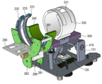
도 1, 2는 본 발명의 일 실시 예에 따른 상완 관절과 손목 관절의 재활을 포함하는 상지 재활 로봇의 외부 구조를 도시한 것이다.
도 3은 본 발명의 일 실시 예에 따른 상지 재활 로봇의 팔꿈치 재활 장치부의 커프 장착 구조를 도시한 것이다.
도 4는 본 발명의 일 실시 예에 따른 상지 재활 로봇의 팔꿈치 재활 장치부의 하부 및 댐퍼 구조를 도시한 것이다.
도 5는 본 발명의 일 실시 예에 따른 상지 재활 로봇의 팔꿈치 재활 장치부의 리미트 포스트바의 구조를 도시한 것이다
도 6은 본 발명의 일 실시 예에 따른 상지 재활 로봇의 베이스 플레이트의 하부의 무게장착부의 구조를 도시한 것이다.1 and 2 show an external structure of an upper extremity rehabilitation robot including rehabilitation of a humerus joint and a wrist joint according to an embodiment of the present invention.
3 illustrates a structure in which a cuff is attached to an elbow rehabilitation device unit of an upper extremity rehabilitation robot according to an embodiment of the present invention.
4 illustrates a lower part of an elbow rehabilitation device and a damper structure of an upper extremity rehabilitation robot according to an embodiment of the present invention.
5 illustrates the structure of a limit post bar of an elbow rehabilitation device unit of an upper extremity rehabilitation robot according to an embodiment of the present invention.
6 illustrates a structure of a weight mounting part under a base plate of an upper extremity rehabilitation robot according to an embodiment of the present invention.
본 출원에서 사용한 용어는 단지 특정한 실시 예를 설명하기 위해 사용된 것으로, 본 발명을 한정하려는 의도가 아니다. 단수의 표현은 문맥상 명백하게 다르게 뜻하지 않는 한, 복수의 표현을 포함한다.Terms used in this application are only used to describe specific embodiments, and are not intended to limit the present invention. Singular expressions include plural expressions unless the context clearly dictates otherwise.
본 출원에서, 어떤 부분이 어떤 구성요소를 "포함"한다고 할 때, 이는 특별히 반대되는 기재가 없는 한 다른 구성요소를 제외하는 것이 아니라 다른 구성요소를 더 포함할 수 있는 것을 의미한다. In this application, when a certain component is said to "include", it means that it may further include other components without excluding other components unless otherwise stated.
또한, 명세서에 기재된 "…부", "…기", "모듈", "장치" 등의 용어는 적어도 하나의 기능이나 동작을 처리하는 단위를 의미하며, 이는 하드웨어나 소프트웨어 또는 하드웨어 및 소프트웨어의 결합으로 구현될 수 있다.In addition, terms such as "...unit", "...unit", "module", and "device" described in the specification mean a unit that processes at least one function or operation, which is hardware or software, or a combination of hardware and software. can be implemented as
또한, 본 발명의 실시 예의 구성 요소를 설명하는 데 있어서, 제1, 제2 등의 용어를 사용할 수 있다. 이러한 용어는 그 구성 요소를 다른 구성 요소와 구별하기 위한 것일 뿐, 그 용어에 의해 해당 구성 요소의 본질이나 차례 또는 순서 등이 한정되지 않는다. 어떤 구성 요소가 다른 구성요소에 '연결', '결합' 또는 '접속'된다고 기재된 경우, 그 구성 요소는 그 다른 구성요소에 직접적으로 연결, 결합 또는 접속될 수 있지만, 그 구성 요소와 그 다른 구성요소 사이에 또 다른 구성 요소가 '연결', '결합' 또는 '접속'될 수도 있다고 이해되어야 할 것이다.Also, terms such as first and second may be used in describing components of an embodiment of the present invention. These terms are only used to distinguish the component from other components, and the nature, order, or order of the corresponding component is not limited by the term. When an element is described as being 'connected', 'coupled' or 'connected' to another element, the element may be directly connected, coupled or connected to the other element, but not between the element and the other element. It should be understood that another component may be 'connected', 'coupled' or 'connected' between elements.
이하 본 발명의 구현에 따른 상완 관절과 손목 관절의 재활을 포함하는 상지 재활 로봇에 대하여 일 실시 예를 통하여 상세하게 설명한다.Hereinafter, an upper limb rehabilitation robot including rehabilitation of the upper arm joint and the wrist joint according to the implementation of the present invention will be described in detail through an embodiment.
도 1, 2는 본 발명의 일 실시 예에 따른 상완 관절과 손목 관절의 재활을 포함하는 상지 재활 로봇의 각각 다른 방향에서 본 외부 구조를 도시한 것이다.1 and 2 show the external structure of the upper extremity rehabilitation robot including the rehabilitation of the upper arm joint and the wrist joint according to an embodiment of the present invention, viewed from different directions.
도 1, 2를 참조하면, 본 발명의 일 실시 예에 따른 상지 재활 로봇은 상지 재활 로봇의 몸체를 하부에서 지지하여 주며, 평판으로 형성된 하부 베이스 플레이트(400), 상기 하부 베이스 플레이트(400)의 일측의 양단에 수직으로 형성된 좌측 지지프레임(411) 및 우측 지지프레임(412), 상기 좌측 지지프레임(411) 및 우측 지지프레임(412)의 상단에 형성된 양측 회전축(415, 416)과 연결되어 상기 회전축을 중심으로 상, 하로 동작되는 회전 브라켓(370) 상기 회전 브라켓(350)의 상부에 고정되며, 상기 회전 브라켓(370)의 동작에 따라 상, 하로 동작되는 상부 지지 플레이트(350), 상기 상부 지지 플레이트(350)의 전방에 장착이 되며, 손목 관절의 좌, 우의 회전운동을 위한 손목 재활 장치부(200), 상기 손목 재활 장치부(200)와 일정 간격을 가지며 상기 상부 지지 플레이트(350)의 후방에 장착이 되고 전완 근육 및 팔꿈 관절의 상, 하 재활운동을 위한 팔꿈치 재활 장치부(300)를 포함한다.1 and 2, the upper extremity rehabilitation robot according to an embodiment of the present invention supports the body of the upper extremity rehabilitation robot from the lower portion, and includes a
도 1, 2를 참조하면, 손목 재활 장치부(200)는 상기 상부 지지 플레이트(350)의 전방 측에 장착되는 제1 받침대 홀더(241), 상기 제1받침대 홀더(241) 상부에 장착되며, 상부가 개방된 반원형 형상으로 형성되고, 손목의 상단을 지지하여 주는 손목 지지몸체(240), 상기 손목 지지 몸체(240)의 앞 측에 장착되며 Y자형상으로 제1수직벽을 형성한 제1수직 가이드판(281), 상기 제1 수직 가이드판(281)과 가이드 써포트(289)에 의해 일정 간격으로 장착되며, Y자형상으로 제2수직벽을 형성한 제2수직 가이드판(282), 상기 제2수직 가이드판(282)과 사이 공간에서 제1수직 가이드판(281)의 하부에 장착되는 제1구동부(220), 상기 제1구동부(220) 축과 연결되며 하나 이상의 톱니로 연결되는 제1 톱니기어체(235), 상기 제1 톱니기어체(235)의 상부에 반원호형 형상으로 형성되며, 반원호형 원주 외측에 톱니가 형성되어, 상기 제1톱니기어체(235)의 톱니와 연결되어 동작되며, 상기 제1수직 가이드판(281)과 제2수직 가이드판(282) 사이의 개방된 상부 공간에서 상기 제1톱니기어체(235)에 연동되어 좌, 우의 회전운동을 하는 제1 손목거치 링부(231) 및 상기 제1 손목거치 링부(231)와 일정 간격으로 평행하게 설치되는 제2 손목거치 링부(232)를 포함한다.1 and 2, the wrist
상기 제1 손목거치 링부(231)와 제2 손목거치 링부(232)의 상단 사이에는 손목이 거치된 상태에서 손목을 고정시킬 수 있는 밴드가 장착되는 밴드바(233)가 더 형성된다.A
또한, 상기 제1구동부(220)의 회전축에는 제1 엔코더 센서(미도시됨)가 장착이 된다.In addition, a first encoder sensor (not shown) is mounted on the rotating shaft of the
본 발명의 일 실시 예에 따르면, 상기 제1구동부(220)가 좌, 우로 회전 구동되면, 상기 제1, 2 손목거치 링부가 좌, 우로 회전 동작되며, 상기 제1 엔코더 센서에 의해 센싱된 신호를 받아서 동작 속도 및 운동량을 측정할 수 있다.According to an embodiment of the present invention, when the
상기 제2 손목거치 링부(232)의 하부 중앙에는 전방 측의 수평의 평판으로 형성되며, 손등을 거치할 수 있는 손등 거치부(290)가 형성된다.At the center of the lower part of the second wrist
도 3은 본 발명의 일 실시 예에 따른 상지 재활 로봇의 팔꿈치 재활 장치부의 커프 장착 구조를 도시한 것이다.3 illustrates a structure in which a cuff is attached to an elbow rehabilitation device unit of an upper extremity rehabilitation robot according to an embodiment of the present invention.
도 3을 참조하면, 팔꿈치 재활 장치부(300)는 상기 상부 지지 플레이트(350)의 중간 위치에 장착되는 제2 받침대 홀더(341), 상기 제2받침대 홀더(341) 상부에 장착되며, 원통관 형상으로 형성되되, 상단으로 팔을 진입할 수 있도록 일정 간격으로 개방된 이격부를 가지는 팔꿈치 지지 커프(330), 상기 팔꿈치 지지 커프(330)의 이격부를 원호형의 커버로 개, 폐하여 주는 팔꿈치 잠금부(335)를 포함한다.Referring to FIG. 3 , the
본 발명의 일 실시 예에 따르면, 상기 상부 지지 플레이트(350)의 양측 옆면은 복수의 요홈이 길이 방향으로 형성된 피카티니 레일 형상으로 형성되며, 상기 제2받침대 홀더(341)의 내측 면에는 상기 상부 지지 플레이트(350)의 양측 옆면의 복수의 요홈과 반대 형상의 요홈이 형성되어 상기 제2받침대 홀더(341)는 상기 상부 지지 플레이트(350)의 길이 방향으로 미끄럼 이동이 가능한 것을 특징으로 한다.According to an embodiment of the present invention, both side surfaces of the
한편, 상기 제2받침대 홀더(341)의 옆면에는 외부면에서 내부로 관통되는 나사홀이 형성된 나사조임부(345)가 형성되며, 상기 나사조임부(345)의 조임나사를 조이면, 상기 제2받침대 홀더(341)가 상기 상부 지지 플레이트(350)에 고정이 되며, 상기 나사조임부(345)의 조임나사를 풀게 되면, 상기 제2받침대 홀더(341)가 상기 상부 지지 플레이트(350)에 미끄럼 이동이 될 수 있다.On the other hand, the side surface of the
이에 따라 상기 제2받침대 홀더(341)의 요홈을 상기 상부 지지 플레이트(350)의 양측 옆면의 복수의 요홈에 끼워 맞춘 상태에서 상기 제2받침대 홀더(341)의 옆면에 형성된 나사조임부(345)의 조임나사를 풀어서, 위치를 변경하거나, 조절을 한 후, 상기 제2받침대 홀더(341)의 나사조임부(345)의 조임나사를 조여서 고정시킬 수 있다. Accordingly, the
상기 손목 재활 장치부(200)는 상부 지지 플레이트 전방에 장착이 되며, 팔꿈치 재활 장치부(300)는 상부 지지 플레이트(350)의 후방에 장착이 된다.The
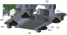
도 4는 본 발명의 일 실시 예에 따른 상지 재활 로봇의 팔꿈치 재활 장치부의 하부 및 댐퍼 구조를 도시한 것이다.4 illustrates a lower part of an elbow rehabilitation device and a damper structure of an upper extremity rehabilitation robot according to an embodiment of the present invention.
도 4를 참조하면, 상기 좌측 지지프레임(411)의 내측면 하부에는 제2구동부(320)가 장착되며, 상기 제2구동부(320)의 축에는 제2롤러구동체(322)가 연결되며, 상기 제2롤러구동체(322)는 좌측 지지프레임(411)의 회전축과 연결된 제2-1 롤러구동체(323)와 회전이 마찰에 의해 연동되도록 설치된다. 따라서, 롤러구동체(323)가 상기 제2구동부(320)에 의해 회전이 연결되며, 상기 회전축이 회전하면, 상기 회전 브라켓(370)의 상, 하 이동 동작함에 따라 상부 지지 플레이트(350)가 상기 회전축을 중심으로 상, 하로 동작하게 된다.Referring to FIG. 4, a
또한, 상기 제2구동부(320)의 회전축에는 제2 엔코더 센서(미도시됨)가 장착이 된다.In addition, a second encoder sensor (not shown) is mounted on the rotating shaft of the
이에 따라 상기 제2구동부(320)가 좌, 우로 회전 구동되면, 상기 팔꿈치 재활 장치부(300)는 상, 하로 동작되며, 상기 제2 엔코더 센서에 의한 센싱신호를 받아서 제어모듈(100)에서 동작 속도 및 운동량을 측정할 수 있다.Accordingly, when the
상기 상부 지지 플레이트(350)와 하부 베이스 플레이트(400) 사이에는 수직에서 일정 각도의 경사각으로 형성된 댐퍼(360)가 연결된다. 상기 댐퍼(360)는 팔꿈치의 굴곡, 신전 운동시에 보조 힘과 저항력을 제공하는 기능을 수행한다.Between the
또한, 하부 베이스 플레이트(400)의 상부에는 위치 및 이동 속도를 측정할 수 있는 IMU 센서(120) 및 상지 재활 로봇을 제어하는 제어 모듈(100)이 장착된다.In addition, the upper part of the
본 발명의 일 실시 예에 따르면, IMU 센서(120)의 센싱신호에 의해 재활 운동 시 모바일 로봇의 위치 및 이동 속도를 파악할 수 있으며, 어깨 운동의 동작 속도 및 운동량을 측정할 수 있다.According to an embodiment of the present invention, the location and movement speed of the mobile robot during rehabilitation can be grasped by the sensing signal of the
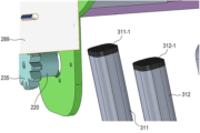
도 5는 본 발명의 일 실시 예에 따른 상지 재활 로봇의 팔꿈치 재활 장치부의 리미트 포스트바의 구조를 도시한 것이다5 illustrates the structure of a limit post bar of an elbow rehabilitation device unit of an upper extremity rehabilitation robot according to an embodiment of the present invention.
도 5를 참조하면, 상기 하부 베이스 플레이트(400)의 전방 일측에는 상기 상부 지지 플레이트(350)의 하부 측 이동을 제한하고, 거치할 수 있는 일정 높이를 가진 리미트 포스트바(311, 312)가 형성된다.Referring to FIG. 5 , limit post bars 311 and 312 having a certain height capable of limiting the movement of the lower side of the
상기 리미트 포스트바(311, 312)의 상단에는 탄력을 가진 실리콘 패드(311-1, 312-1)가 장착이 된다.Elastic silicon pads 311-1 and 312-1 are mounted on the upper ends of the limit post bars 311 and 312.
상기 실리콘 패드(311-1, 312-1)는 팔꿈치 동작 시에 하부 베이스 플레이트(400)와 리미트 포스트바(311, 312)의 접촉으로 인한 충격을 완화해 주는 기능을 가진다.The silicon pads 311-1 and 312-1 have a function of mitigating shock caused by contact between the
도 6은 본 발명의 일 실시 예에 따른 상지 재활 로봇의 베이스 플레이트의 하부의 무게장착부의 구조를 도시한 것이다.6 illustrates a structure of a weight mounting part under a base plate of an upper extremity rehabilitation robot according to an embodiment of the present invention.
도 6을 참조하면, 하부 베이스 플레이트(400)의 하부에는 무게추(450)를 장착하기 위한 하부 공간의 주변에 L 형의 복수의 서포트 클램프(451)가 형성된다. Referring to FIG. 6 , a plurality of L-shaped support clamps 451 are formed in the lower portion of the
본 발명의 일 실시 예에 따른 서포트 클램프(451)는 삽입을 위한 개방구 방향을 제외한 3 방향에 장착이 되며, 사용자가 필요한 무게의 무게추(450)를 서포트 클램프(451) 내에 삽입하여 상기 선택적으로 교체 및 삽입할 수 있다.The
또한, 상기 서포트 클램프(451)의 하부면에는 상기 무게추(450)를 삽입한 후, 고정시킬 수 있는 조임 나사부(451-1)를 더 포함할 수 있다.In addition, the lower surface of the
또한, 하부 베이스 플레이트(400)의 하부의 각 모서리에는 바닥에 수평 위치를 조절할 수 있는 다리 받침대(421, 422)를 더 포함할 수 있다.In addition, leg rests 421 and 422 capable of adjusting a horizontal position on the floor may be further included at each corner of the lower portion of the
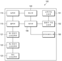
도 7은 본 발명의 일 실시 예에 따른 제어 모듈(100)의 블록도를 도시한 것이다.7 shows a block diagram of a
도 7을 참조하면, 본 발명의 일 실시 예에 따른 제어 모듈(100)은 사용자에 의해 제어조건이 입력되는 입력부(110), 상지 재활 로봇의 제어 상태가 출력되는 출력부(115), 상기 제1 엔코더 센서의 센싱신호가 입력되는 제1 엔코더 신호입력부(121), 상기 제2 엔코더 센서의 센싱신호가 입력되는 제2 엔코더 신호입력부(122), 상기 IMU 센서의 센싱신호가 입력되는 IMU 신호입력부(123), 상기 입력부(110) 및 출력부(115)의 기능을 원격에서 제어할 수 있도록 무선으로 연결하여 주는 통신부(140), 상기 각부를 제어하는 제어부(190), 상기 제어부(190)의 제어신호에 의해 상기 제1구동부(220)에 제어신호를 전송하는 손목구동 신호부(151), 상기 제어부(190)의 제어신호에 의해 상기 제2구동부(320)에 제어신호를 전송하는 팔꿈치 구동 신호부(151) 및 상지 재활 로봇의 제어 및 상태가 저장되는 데이터베이스부(160)를 포함한다.Referring to FIG. 7 , the
본 발명의 일 실시 예에 따른 입력부(110) 및 출력부(115)는 하나의 터치스크린으로 동작될 수 있다.The
사용자는 상기 입력부(110)를 통하여 자력으로 재활훈련 동작을 수행하는 수동 동작 및 동력의 힘에 의해 수동적으로 재활훈련 동작을 수행하는 자동 동작을 선택하여 동작시킬 수 있다.Through the
자동 모드에서는 사용자가 운동강도를 약-중- 강의 범위를 선택한 다음, 손등을 상기 손등거치부(290)에 거치한 상태에서 손목을 밴드에 의해 고정시킨 다음 운전 동작을 선택을 하면, 제1구동부(220)가 작동을 하여 손목 재활 운동을 실시할 수 있다. 이 경우, 제1 엔코더 센서에 의해 운동 속도를 측정할 수 있다.In the automatic mode, when the user selects a range of exercise intensity from weak to medium to strong, fixes the wrist with the band while holding the back of the hand on the back of the
또한, 자동 모드에서 사용자가 운동강도를 약-중- 강의 범위를 선택한 다음, 상기 제2받침대 홀더(341)를 상기 상부 지지 플레이트(350)로부터 미끄럼 이동하여 팔 길이를 조정하고, 팔을 팔꿈치 지지 커프(330)의 상단 이격부를 통하여 넣은 다음, 팔꿈치 잠금부(335)를 덮어서 고정시키고, 운전 동작을 선택을 하면, 제2구동부(320)가 작동을 하여 팔꿈치 재활 운동을 실시할 수 있다. 이 경우, 제2 엔코더 센서에 의해 운동 속도를 측정할 수 있다.In addition, in the automatic mode, after the user selects a range of about-medium-strong exercise intensity, the
수동 모드에서는 상기 제1구동부(220) 및 제2구동부(320)는 동작하지 않은 상태에서 사용자가 자력으로 손목 및 팔꿈치 운동을 실시할 수 있다. 수동 모드에서는 제1 구동부(220) 및 제1 톱니기어체(235)가 저항력 및 부담으로 작용하여 자력에 의한 손목 운동으로 동작될 수 있으며, 제1 엔코더 센서에 의해 운동 속도를 측정할 수 있다.In the manual mode, the
또한, 수동 모드에서는 제2 구동부(220), 제2롤러구동체(322) 및 댐퍼(360)가 저항력 및 부담으로 작용하여 자력에 의한 손목 운동으로 동작될 수 있으며, 제2 엔코더 센서에 의해 운동 속도를 측정할 수 있다.In addition, in the manual mode, the
본 발명의 일 실시 예에 따른 상지 재활 로봇은 바닥이나, 테이블에 상기 베이스 플레이트(400)를 위치한 상태에서 손목 재활운동 및 팔꿈치 재활운동을 적용할 수 있다.The upper extremity rehabilitation robot according to an embodiment of the present invention may apply wrist rehabilitation exercise and elbow rehabilitation exercise in a state where the
또한, 본 발명의 일 실시 예에 따른 상지 재활 로봇을 장착한 상태로 들어서 어깨를 상, 하, 좌, 우로 움직이는 어깨 재활운동에 적용될 수 있으며, 이 경우 IMU 센서(120)에 의해 어깨 동작의 범위, 운동속도 및 운동량을 측정할 수 있다.In addition, it can be applied to a shoulder rehabilitation exercise in which the shoulder is moved up, down, left, and right by lifting the upper extremity rehabilitation robot according to an embodiment of the present invention. In this case, the range of shoulder motion is determined by the
본 발명의 일 실시 예에 따른 상지 재활 로봇은 상부 지지 플레이트의 피카티니 레일과 제2받침대 홀더(341)를 이용하여 다양한 팔 길이에 대응할 수 있다.The upper extremity rehabilitation robot according to an embodiment of the present invention can respond to various arm lengths by using the Picatinny rail of the upper support plate and the
본 발명의 일 실시 예에 따른 상지 재활 로봇은 기력이 없는 환자도 스스로 상지 재활이 가능하도록 도움을 줄 수 있다.The upper extremity rehabilitation robot according to an embodiment of the present invention can help a patient without energy to perform upper extremity rehabilitation on their own.
본 발명의 일 실시 예에 따른 상지 재활 로봇은 손목 1자유도, 팔꿈치 1자유도 및 어깨 2자유도의 재활 운동이 가능하다.The upper extremity rehabilitation robot according to an embodiment of the present invention is capable of rehabilitation exercise with 1 degree of freedom of the wrist, 1 degree of freedom of the elbow, and 2 degrees of freedom of the shoulder.
본 발명의 일 실시 예에 따른 상지 재활 로봇은 자동, 수동의 선택적 적용으로 손목과 팔꿈치의 능동 및 수동 재활 운동이 가능하다.The upper extremity rehabilitation robot according to an embodiment of the present invention is capable of active and passive rehabilitation of the wrist and elbow by selective application of automatic and passive.
본 발명의 일 실시 예에 따른 상지 재활 로봇은 무게추(450)를 선택적으로 교체하여 환자의 상지 근력에 따라 무게 조절이 가능하도록 할 수 있다.The upper extremity rehabilitation robot according to an embodiment of the present invention can selectively replace the
본 발명의 일 실시 예에 따른 상지 재활 로봇은 환자 스스로 가정 혹은 병원에서 손목, 팔꿈치, 제한된 운동범위의 어깨의 재활 훈련이 가능하다.The upper extremity rehabilitation robot according to an embodiment of the present invention enables the patient to perform rehabilitation training of the wrist, elbow, and shoulder with a limited range of motion at home or in a hospital.
또한, 각 관절의 힘과 가동 범위를 측정하여 재활 치료 운동 중인 환자 관절의 경직된 정도를 수치적으로 진단 가능할 수 있으며, 수집된 데이터를 활용하여 전문의가 다음 훈련에 대한 진단이 가능할 수 있다.In addition, by measuring the strength and range of motion of each joint, it may be possible to numerically diagnose the degree of stiffness of the patient's joint during rehabilitation exercise, and a specialist may be able to diagnose the next training using the collected data.
본 발명의 일 실시 예에 따른 상지 재활 로봇은 사용자의 상지 운동력이 원활하지 않거나, 근력이 충분하지 않은 경우에도 동력에 의해 운동방향으로 동작하도록 하여, 근력이 상승될 때까지 반복적으로 운동을 유지시킬 수 있는 기능을 가질 수 있다..The upper extremity rehabilitation robot according to an embodiment of the present invention operates in the direction of motion by power even when the user's upper extremity motion is not smooth or the muscular strength is not sufficient, thereby repeatedly maintaining the motion until the muscular strength is increased. It can have features that can...
100: 제어모듈
120: IMU 센서
110: 입력부
115: 출력부
121: 제1 엔코더 신호입력부
122: 제2 엔코더 신호입력부
123: IMU 신호입력부
140: 통신부
151: 손목구동 신호부
152: 팔꿈치 구동 신호부
160: 데이터베이스부.
190: 제어부(190),
200: 손목 재활 장치부
220: 제1구동부
231: 제1 손목거치 링부
232: 제2 손목거치 링부
235: 제1 톱니기어체
241: 제1 받침대 홀더
281: 제1수직 가이드판
282: 제2수직 가이드판
290: 손등 거치부
311, 312: 리미트 포스트바
311-1, 312-1: 실리콘 패드
330: 팔꿈치 지지 커프
335: 팔꿈치 잠금부
341: 제2 받침대 홀더
345: 나사조임부
350: 상부 지지 플레이트
360: 댐퍼
400: 베이스 플레이트
411; 좌측 지지프레임
412: 우측 지지프레임
415, 415: 회전축)
450: 무게추
451: 서포트 클램프100: control module
120: IMU sensor
110: input unit
115: output unit
121: first encoder signal input unit
122: second encoder signal input unit
123: IMU signal input unit
140: communication department
151: wrist drive signal unit
152: elbow drive signal unit
160: database unit.
190:
200: wrist rehabilitation device
220: first driving unit
231: first wrist rest ring unit
232: second wrist rest ring unit
235: first gear body
241: first pedestal holder
281: first vertical guide plate
282: second vertical guide plate
290: back of hand holder
311, 312: limit post bar
311-1, 312-1: silicone pad
330: elbow support cuff
335: elbow locking part
341: second pedestal holder
345: screw fastening
350: upper support plate
360: damper
400: base plate
411; left support frame
412: right support frame
415, 415: rotation axis)
450: weight
451: support clamp
Claims (11)
상기 상지 재활 로봇은,
상기 상지 재활 로봇의 몸체를 하부에서 지지하여 주며, 평판으로 형성된 하부 베이스 플레이트;
상기 하부 베이스 플레이트의 일측의 양단에 수직으로 형성된 제1 지지프레임 및 제2 지지프레임;
상기 제1지지프레임 및 제2 지지프레임의 상단에 형성된 양측 회전축과 연결되어 상기 회전축을 중심으로 상, 하로 동작되는 회전 브라켓;
상기 회전 브라켓의 상부에 고정되며, 상기 회전 브라켓의 동작에 따라 상, 하로 동작되는 상부 지지 플레이트;
상기 상부 지지 플레이트의 전방에 장착이 되며, 손목 관절의 좌, 우의 회전운동을 위한 손목 재활 장치부; 및
상기 손목 재활 장치부와 일정 간격을 가지며 상기 상부 지지 플레이트의 후방에 장착이 되고 전완 근육 및 팔꿈치 관절의 상, 하 재활운동을 위한 팔꿈치 재활 장치부; 를 포함하는 것을 특징으로 하는 상지 재활 로봇.In the upper limb rehabilitation robot including rehabilitation of the upper arm joint and the wrist joint,
The upper limb rehabilitation robot,
a lower base plate formed of a flat plate and supporting the body of the upper extremity rehabilitation robot from a lower portion;
a first support frame and a second support frame vertically formed at both ends of one side of the lower base plate;
a rotation bracket connected to both rotation shafts formed at upper ends of the first support frame and the second support frame and operated up and down around the rotation shaft;
an upper support plate fixed to an upper portion of the rotation bracket and moved up and down according to the operation of the rotation bracket;
a wrist rehabilitation device for left and right rotational movement of the wrist joint, which is mounted on the front of the upper support plate; and
an elbow rehabilitation device for performing upper and lower rehabilitation exercises of the forearm muscle and elbow joint, and is mounted on the rear side of the upper support plate at a predetermined distance from the wrist rehabilitation device; Upper limb rehabilitation robot comprising a.
상기 손목 재활 장치부는,
상기 상부 지지 플레이트의 전방 측에 장착되는 제1 받침대 홀더;
상기 제1받침대 홀더 상부에 장착되며, 상부가 개방된 반원형 형상으로 형성되고, 손목의 상단을 지지하여 주는 손목 지지몸체;
상기 손목 지지 몸체의 앞 측에 장착되며 Y자 형상으로 제1수직벽을 형성한 제1수직 가이드판;
상기 제1 수직 가이드판과 가이드 써포트에 의해 일정 간격으로 장착되며, Y자 형상으로 제2수직벽을 형성한 제2수직 가이드판;
상기 제2수직 가이드판과의 사이 공간에서 상기 제1수직 가이드판의 하부에 장착되는 제1구동부; 및
상기 제1구동부와 연동되어 상기 제1수직 가이드판과 제2수직 가이드판 사이의 개방된 상부 공간에서 좌, 우의 회전운동을 하는 제1 손목거치 링부; 를 포함하는 것을 특징으로 하는 상지 재활 로봇.According to claim 1,
The wrist rehabilitation device unit,
a first pedestal holder mounted on a front side of the upper support plate;
a wrist support body mounted on an upper portion of the first pedestal holder, formed in a semicircular shape with an open upper portion, and supporting an upper end of the wrist;
a first vertical guide plate mounted on the front side of the wrist support body and forming a first vertical wall in a Y shape;
a second vertical guide plate mounted at regular intervals by the first vertical guide plate and the guide support and forming a second vertical wall in a Y-shape;
a first driving unit mounted below the first vertical guide plate in a space between the second vertical guide plate; and
a first wrist rest ring unit that interlocks with the first driving unit and performs left and right rotational movements in an open upper space between the first vertical guide plate and the second vertical guide plate; Upper limb rehabilitation robot comprising a.
상기 제1 손목거치 링부는 반원호형 형상으로 형성되며, 상기 반원호형 원주 외측에 톱니가 형성되고,
상기 제1구동부는 상기 제1구동부 축과 연결되며 하나 이상의 톱니로 연결되는 제1 톱니기어체의 상부에, 상기 반원호형 원주 외측에 톱니와 연결되어 연동되는 것을 특징으로 하는 상지 재활 로봇.According to claim 2,
The first wrist rest ring part is formed in a semi-arc shape, and teeth are formed on the outside of the semi-arc shape circumference,
The upper limb rehabilitation robot, characterized in that the first driving unit is connected to the first driving unit axis and interlocks with the upper part of the first gear body connected by one or more teeth and is connected to the teeth outside the semicircular circumference.
상기 재활 로봇은
상기 제1 손목거치 링부와 일정 간격으로 평행하게 설치되는 제2 손목거치 링부를 더 포함하고,
상기 제2 손목거치 링부의 하부 중앙에는 전방 측의 수평의 평판으로 형성되며, 손등을 거치할 수 있는 손등 거치부가 설치되며,
상기 제1 손목거치 링부와 제2 손목거치 링부의 상단 사이에는 손목이 거치된 상태에서 손목을 고정시킬 수 있는 밴드가 장착되는 밴드바가 형성된 것을 특징으로 하는 상지 재활 로봇.According to claim 2,
The rehabilitation robot
Further comprising a second wrist rest ring part installed in parallel with the first wrist rest ring part at regular intervals,
At the center of the lower part of the second wrist rest ring part, a horizontal flat plate on the front side is formed, and a hand holding part capable of holding the back of the hand is installed.
An upper limb rehabilitation robot, characterized in that a band bar to which a band for fixing the wrist is mounted is formed between upper ends of the first wrist support ring part and the second wrist support ring part.
상기 팔꿈치 재활 장치부는,
상기 상부 지지 플레이트의 중간 위치에 장착되는 제2 받침대 홀더;
상기 제2받침대 홀더 상부에 장착되며, 원통관 형상으로 형성되되, 상단으로 팔을 진입할 수 있도록 일정 간격으로 개방된 이격부를 가지는 팔꿈치 지지 커프; 및, 상기 팔꿈치 지지 커프의 이격부를 원호형의 커버로 개, 폐하여 주는 팔꿈치 잠금부; 를 포함하는 것을 특징으로 하는 상지 재활 로봇.According to claim 2,
The elbow rehabilitation device unit,
a second pedestal holder mounted at an intermediate position of the upper support plate;
an elbow support cuff mounted on the upper part of the second pedestal holder, formed in a cylindrical tube shape, and having a spaced part open at regular intervals so that the arm can enter the upper end; and an elbow locking part that opens and closes the separated part of the elbow supporting cuff with an arc-shaped cover. Upper limb rehabilitation robot comprising a.
상기 상부 지지 플레이트의 양측 옆면은 복수의 요홈이 길이 방향으로 형성된 피카티니 레일 형상으로 형성되며, 상기 제2받침대 홀더의 내측 면에는 상기 상부 지지 플레이트의 양측 옆면의 복수의 요홈과 반대 형상의 요홈이 형성되어 상기 제2받침대 홀더는 상기 상부 지지 플레이트의 길이 방향으로 미끄럼 이동이 가능한 것을 특징으로 하는 상지 재활 로봇..According to claim 5,
Both side surfaces of the upper support plate are formed in a Picatinny rail shape with a plurality of grooves formed in the longitudinal direction, and grooves opposite to the plurality of grooves on both side surfaces of the upper support plate are formed on the inner surface of the second pedestal holder. The upper limb rehabilitation robot, characterized in that the second pedestal holder can slide in the longitudinal direction of the upper support plate.
상기 제1 지지프레임에는 내측면 하부에 제2구동부가 장착되며, 제2구동부가 장착되며, 상기 제2구동부의 축에는 제2롤러구동체가 연결되며, 상기 제2롤러구동체는 상기 제1 지지프레임의 회전축과 연결된 제2-1 롤러구동체와 회전이 마찰에 의해 연동되도록 설치되는 것을 특징으로 하는 상지 제활 로봇.According to claim 5,
A second driving unit is mounted on a lower portion of the inner surface of the first support frame, a second driving unit is mounted, a second roller driving body is connected to an axis of the second driving unit, and the second roller driving body is connected to the first supporting frame. An upper limb rehabilitation robot characterized in that it is installed so that rotation is interlocked with the 2-1 roller actuator connected to the rotation axis of the frame by friction.
상기 상부 지지 플레이트와 하부 베이스 플레이트 사이에는 수직에서 일정 각도의 경사각으로 형성된 댐퍼로 연결되며,
상기 하부 베이스 플레이트의 전방 일측에는 상기 상부 지지 플레이트의 하부 측 이동을 제한하고, 거치할 수 있는 일정 높이를 가진 리미트 포스트바가 형성된 것을 특징으로 하는 상지 재활 로봇.According to claim 5,
Between the upper support plate and the lower base plate, a damper formed at an inclination angle of a certain angle is connected from the vertical,
The upper limb rehabilitation robot, characterized in that, a limit post bar having a predetermined height capable of limiting movement of the lower side of the upper support plate and being mounted is formed on one front side of the lower base plate.
상기 하부 베이스 플레이트의 하부에는 무게추를 장착하기 위한 하부 공간의 주변에 L 형의 복수의 서포트 클램프가 형성된 것을 특징으로 하는 상지 재활 로봇.According to claim 5,
An upper limb rehabilitation robot, characterized in that a plurality of L-shaped support clamps are formed around a lower space for mounting weights in the lower part of the lower base plate.
상기 제1구동부의 축에는 제1 엔코더 센서가 장착이 되고, 상기 제2구동부의 축에는 제2엔코더 센서가 장착이 되며,
상기 하부 베이스 플레이트의 상부에는 위치 및 이동 속도를 측정할 수 있는 IMU 센서 및 상기 상지 재활 로봇을 제어하는 제어 모듈이 장착된 것을 특징으로 하며,
상기 제어 모듈은,
사용자에 의해 제어조건이 입력되는 입력부;
상기 상지 재활 로봇의 제어 상태가 출력되는 출력부;
상기 제1 엔코더 센서의 센싱신호가 입력되는 제1 엔코더 신호입력부;
상기 제2 엔코더 센서의 센싱신호가 입력되는 제2 엔코더 신호입력부;
상기 IMU 센서의 센싱신호가 입력되는 IMU 신호입력부;
상기 입력부 및 출력부의 기능을 원격에서 제어할 수 있도록 무선으로 연결하여 주는 통신부;
제어부의 제어신호에 의해 상기 제1구동부에 제어신호를 전송하는 손목구동 신호부;
상기 제어부의 제어신호에 의해 상기 제2구동부에 제어신호를 전송하는 팔꿈치 구동 신호부; 및
상기 상지 재활 로봇의 제어 및 상태가 저장되는 데이터베이스부; 를 포함하는 것을 특징으로 하는 상지 재활 로봇.According to claim 5,
A first encoder sensor is mounted on the shaft of the first drive unit, and a second encoder sensor is mounted on the shaft of the second drive unit.
An IMU sensor capable of measuring position and movement speed and a control module for controlling the upper extremity rehabilitation robot are mounted on the upper part of the lower base plate,
The control module,
an input unit through which control conditions are input by a user;
an output unit outputting a control state of the upper extremity rehabilitation robot;
a first encoder signal input unit to which the sensing signal of the first encoder sensor is input;
a second encoder signal input unit to which the sensing signal of the second encoder sensor is input;
an IMU signal input unit into which a sensing signal of the IMU sensor is input;
a communication unit for wirelessly connecting functions of the input unit and the output unit to be remotely controlled;
a wrist drive signal unit for transmitting a control signal to the first drive unit in response to a control signal from the control unit;
An elbow drive signal unit for transmitting a control signal to the second drive unit by a control signal of the control unit; and
a database unit for storing control and status of the upper extremity rehabilitation robot; Upper limb rehabilitation robot comprising a.
상기 사용자가 상기 입력부를 통하여 자력으로 재활훈련 동작을 수행하는 수동 동작 또는 동력의 힘에 의해 수동적으로 재활훈련 동작을 수행하는 자동 동작을 선택하는 것에 의해 상기 수동 동작 및 자동 동작을 수행하는 것을 특징으로 하는 상지 재활 로봇.
According to claim 10,
The manual operation and the automatic operation are performed by the user selecting a manual operation for performing a rehabilitation operation by one's own power through the input unit or an automatic operation for passively performing a rehabilitation training operation by the power of power. upper extremity rehabilitation robot.
Priority Applications (1)
| Application Number | Priority Date | Filing Date | Title |
|---|---|---|---|
| KR1020210163493A KR20230077018A (en) | 2021-11-24 | 2021-11-24 | Upper limb rehabilitation robot having rehabilitation shoulder joint and wrist joint |
Applications Claiming Priority (1)
| Application Number | Priority Date | Filing Date | Title |
|---|---|---|---|
| KR1020210163493A KR20230077018A (en) | 2021-11-24 | 2021-11-24 | Upper limb rehabilitation robot having rehabilitation shoulder joint and wrist joint |
Publications (1)
| Publication Number | Publication Date |
|---|---|
| KR20230077018A true KR20230077018A (en) | 2023-06-01 |
Family
ID=86770908
Family Applications (1)
| Application Number | Title | Priority Date | Filing Date |
|---|---|---|---|
| KR1020210163493A Ceased KR20230077018A (en) | 2021-11-24 | 2021-11-24 | Upper limb rehabilitation robot having rehabilitation shoulder joint and wrist joint |
Country Status (1)
| Country | Link |
|---|---|
| KR (1) | KR20230077018A (en) |
Citations (2)
| Publication number | Priority date | Publication date | Assignee | Title |
|---|---|---|---|---|
| KR101163903B1 (en) | 2010-08-13 | 2012-07-09 | 한국과학기술원 | Robot shoulder appratus for stroke patients rehabilitation |
| KR101465176B1 (en) | 2012-12-21 | 2014-11-25 | 한국기계연구원 | Robot for rehablitating an upper extremity |
-
2021
- 2021-11-24 KR KR1020210163493A patent/KR20230077018A/en not_active Ceased
Patent Citations (2)
| Publication number | Priority date | Publication date | Assignee | Title |
|---|---|---|---|---|
| KR101163903B1 (en) | 2010-08-13 | 2012-07-09 | 한국과학기술원 | Robot shoulder appratus for stroke patients rehabilitation |
| KR101465176B1 (en) | 2012-12-21 | 2014-11-25 | 한국기계연구원 | Robot for rehablitating an upper extremity |
Similar Documents
| Publication | Publication Date | Title |
|---|---|---|
| CN110237501B (en) | Ankle joint training adapter and rehabilitation training device | |
| KR101065420B1 (en) | Wearable robotic device for upper limb movement | |
| CN109276407B (en) | Elbow joint training adapter and rehabilitation training device | |
| Williams et al. | A robot for wrist rehabilitation | |
| KR101099063B1 (en) | Double Arm Rehabilitation Exercise Equipment Using Pneumatic Muscle | |
| JP2012527907A (en) | Apparatus for therapeutic treatment and / or training of human lower limbs | |
| US20160144229A1 (en) | Modular multi-joint rehabilitation training system and method | |
| TW200946095A (en) | Rehabilitating and training device and controlling method thereof | |
| CN207341899U (en) | A kind of Multifunctional rehabilitation exercise equipment | |
| WO2013168738A1 (en) | Exercise training apparatus | |
| CN109011404A (en) | Healing and training shoulder joint Medical Devices | |
| WO2011076240A1 (en) | Robotic arm trainer | |
| KR101964039B1 (en) | Customized rehabilitation exercise equipment for elder which is into lower body. | |
| JP2017524410A (en) | Leg orthodontic appliance and orthodontic appliance | |
| JP2023119062A (en) | Training instrument | |
| WO2008047355A2 (en) | Methods and gyroscopic apparatus for rehabilitation training | |
| CN216536718U (en) | Multifunctional active and passive rehabilitation training device | |
| KR102104262B1 (en) | Riding Type Apparatus for Training Walk | |
| KR20160056235A (en) | Apparatus of hand rehabilitation | |
| EP4454627B1 (en) | Physiotherapy treatment device | |
| US20240148593A1 (en) | Apparatus for limb rehabilitation and method of using same | |
| WO2025062260A1 (en) | Manipulation unit and rehabilitation apparatus for the upper limb | |
| KR20180076400A (en) | Customized Rehabilitation exercise equipment for elders which is adduction abduction of pelvic limb. | |
| KR20230145636A (en) | Devices for rehabilitation exercise | |
| CN209392331U (en) | A kind of rehabilitation training robot for function of hand |
Legal Events
| Date | Code | Title | Description |
|---|---|---|---|
| PA0109 | Patent application |
St.27 status event code: A-0-1-A10-A12-nap-PA0109 |
|
| PA0201 | Request for examination |
St.27 status event code: A-1-2-D10-D11-exm-PA0201 |
|
| PN2301 | Change of applicant |
St.27 status event code: A-3-3-R10-R13-asn-PN2301 St.27 status event code: A-3-3-R10-R11-asn-PN2301 |
|
| R18-X000 | Changes to party contact information recorded |
St.27 status event code: A-3-3-R10-R18-oth-X000 |
|
| P22-X000 | Classification modified |
St.27 status event code: A-2-2-P10-P22-nap-X000 |
|
| D13-X000 | Search requested |
St.27 status event code: A-1-2-D10-D13-srh-X000 |
|
| D14-X000 | Search report completed |
St.27 status event code: A-1-2-D10-D14-srh-X000 |
|
| PG1501 | Laying open of application |
St.27 status event code: A-1-1-Q10-Q12-nap-PG1501 |
|
| E902 | Notification of reason for refusal | ||
| PE0902 | Notice of grounds for rejection |
St.27 status event code: A-1-2-D10-D21-exm-PE0902 |
|
| E601 | Decision to refuse application | ||
| PE0601 | Decision on rejection of patent |
St.27 status event code: N-2-6-B10-B15-exm-PE0601 |
|
| P22-X000 | Classification modified |
St.27 status event code: A-2-2-P10-P22-nap-X000 |
|
| R18 | Changes to party contact information recorded |
Free format text: ST27 STATUS EVENT CODE: A-3-3-R10-R18-OTH-X000 (AS PROVIDED BY THE NATIONAL OFFICE) |
|
| R18-X000 | Changes to party contact information recorded |
St.27 status event code: A-3-3-R10-R18-oth-X000 |
|
| R18 | Changes to party contact information recorded |
Free format text: ST27 STATUS EVENT CODE: A-3-3-R10-R18-OTH-X000 (AS PROVIDED BY THE NATIONAL OFFICE) |
|
| R18-X000 | Changes to party contact information recorded |
St.27 status event code: A-3-3-R10-R18-oth-X000 |