KR20250040629A - Load port installation position adjustment mechanism - Google Patents
Load port installation position adjustment mechanism Download PDFInfo
- Publication number
- KR20250040629A KR20250040629A KR1020257001402A KR20257001402A KR20250040629A KR 20250040629 A KR20250040629 A KR 20250040629A KR 1020257001402 A KR1020257001402 A KR 1020257001402A KR 20257001402 A KR20257001402 A KR 20257001402A KR 20250040629 A KR20250040629 A KR 20250040629A
- Authority
- KR
- South Korea
- Prior art keywords
- load port
- wall surface
- axis direction
- axis
- room
- Prior art date
- Legal status (The legal status is an assumption and is not a legal conclusion. Google has not performed a legal analysis and makes no representation as to the accuracy of the status listed.)
- Pending
Links
Images







Classifications
-
- H—ELECTRICITY
- H10—SEMICONDUCTOR DEVICES; ELECTRIC SOLID-STATE DEVICES NOT OTHERWISE PROVIDED FOR
- H10P—GENERIC PROCESSES OR APPARATUS FOR THE MANUFACTURE OR TREATMENT OF DEVICES COVERED BY CLASS H10
- H10P72/00—Handling or holding of wafers, substrates or devices during manufacture or treatment thereof
- H10P72/30—Handling or holding of wafers, substrates or devices during manufacture or treatment thereof for conveying, e.g. between different workstations
- H10P72/34—Handling or holding of wafers, substrates or devices during manufacture or treatment thereof for conveying, e.g. between different workstations the wafers being stored in a carrier, involving loading and unloading
- H10P72/3408—Docking arrangements
-
- H01L21/67775—
-
- H—ELECTRICITY
- H10—SEMICONDUCTOR DEVICES; ELECTRIC SOLID-STATE DEVICES NOT OTHERWISE PROVIDED FOR
- H10P—GENERIC PROCESSES OR APPARATUS FOR THE MANUFACTURE OR TREATMENT OF DEVICES COVERED BY CLASS H10
- H10P72/00—Handling or holding of wafers, substrates or devices during manufacture or treatment thereof
- H10P72/50—Handling or holding of wafers, substrates or devices during manufacture or treatment thereof for positioning, orientation or alignment
-
- H01L21/68—
-
- H—ELECTRICITY
- H10—SEMICONDUCTOR DEVICES; ELECTRIC SOLID-STATE DEVICES NOT OTHERWISE PROVIDED FOR
- H10P—GENERIC PROCESSES OR APPARATUS FOR THE MANUFACTURE OR TREATMENT OF DEVICES COVERED BY CLASS H10
- H10P72/00—Handling or holding of wafers, substrates or devices during manufacture or treatment thereof
- H10P72/04—Apparatus for manufacture or treatment
- H10P72/0451—Apparatus for manufacturing or treating in a plurality of work-stations
- H10P72/0464—Apparatus for manufacturing or treating in a plurality of work-stations characterised by the construction of the transfer chamber
-
- H—ELECTRICITY
- H10—SEMICONDUCTOR DEVICES; ELECTRIC SOLID-STATE DEVICES NOT OTHERWISE PROVIDED FOR
- H10P—GENERIC PROCESSES OR APPARATUS FOR THE MANUFACTURE OR TREATMENT OF DEVICES COVERED BY CLASS H10
- H10P72/00—Handling or holding of wafers, substrates or devices during manufacture or treatment thereof
- H10P72/30—Handling or holding of wafers, substrates or devices during manufacture or treatment thereof for conveying, e.g. between different workstations
Landscapes
- Container, Conveyance, Adherence, Positioning, Of Wafer (AREA)
Abstract
로드 포트 설치 위치 조정 기구를, 대략 폐지된 기판 반송 공간을 내부에 구성하는 반송실(2)의 벽면(2F)에 로드 포트(1)를 설치하는 위치를 조정 가능한 로드 포트 설치 위치 조정 기구 T로서, 벽면(2F)의 폭 방향 W에 있어서의 로드 포트(1)의 위치를 조정하는 X축 방향 조정부 T1과, 벽면(2F)의 두께 방향 D에 있어서의 로드 포트(1)의 위치를 조정하는 Y축 방향 조정부 T2와, 벽면(2F)의 높이 방향 H에 있어서의 로드 포트(1)의 위치를 조정하는 Z축 방향 조정부 T3을 구비하고, 이들 X축 방향 조정부 T1, Y축 방향 조정부 T2 및 Z축 방향 조정부 T3을 집약한 3축 방향 조정 기구 T4를, 벽면(2F)의 상단에 형성된 설치 구멍(2t)을 이용하여 벽면에 설치하는 구성으로 함으로써, 로드 포트(1)를 반송실(2)의 벽면에 고정밀도로 설치하는 작업성이 향상된다.A load port installation position adjustment mechanism is provided as a load port installation position adjustment mechanism T which can adjust the position of installing a load port (1) on a wall surface (2F) of a transfer room (2) which constitutes a roughly abolished substrate transfer space inside, and which comprises an X-axis direction adjustment part T1 which adjusts the position of the load port (1) in the width direction W of the wall surface (2F), a Y-axis direction adjustment part T2 which adjusts the position of the load port (1) in the thickness direction D of the wall surface (2F), and a Z-axis direction adjustment part T3 which adjusts the position of the load port (1) in the height direction H of the wall surface (2F), and by configuring a three-axis direction adjustment mechanism T4 which integrates these X-axis direction adjustment parts T1, Y-axis direction adjustment parts T2, and Z-axis direction adjustment parts T3 to be installed on the wall surface using an installation hole (2t) formed on the upper end of the wall surface (2F), the workability of installing the load port (1) on the wall surface of the transfer room (2) with high precision is improved.

Description
본 발명은, 기판 반송 장치의 전방면에 설치하는 로드 포트의 위치(설치 위치)를 조정하는 로드 포트 설치 위치 조정 기구에 관한 것이다.The present invention relates to a load port installation position adjustment mechanism for adjusting the position (installation position) of a load port installed on the front surface of a substrate return device.
예를 들어 반도체의 제조 공정에 있어서는, 수율이나 품질의 향상을 위해, 클린룸 내에서의 웨이퍼(기판의 일례)의 처리가 이루어지고 있다. 근년에는, 웨이퍼의 주위의 국소적인 공간에 대해서만 청정도를 보다 향상시키는 「미니 인바이런먼트 방식」을 도입하여, 웨이퍼의 반송 그 밖의 처리를 행하는 수단이 채용되고 있다. 미니 인바이런먼트 방식에서는, 하우징의 내부에서 대략 폐지된 웨이퍼 반송실(이하, 반송실)의 벽면의 일부를 구성함과 함께, 고청정의 내부 공간에 웨이퍼 등의 반송 대상물이 수납된 저장 용기인 FOUP(Front-Opening Unified Pod)를 적재하고, FOUP의 도어에 밀착한 상태에서 당해 FOUP 도어를 개폐시키는 기능을 갖는 로드 포트가 반송실에 인접하여 마련되어 있다.For example, in the semiconductor manufacturing process, wafers (an example of substrates) are processed in a clean room in order to improve yield and quality. In recent years, a "mini-environment method" has been introduced to further improve cleanliness only in a localized space around the wafer, and a means for performing wafer return and other processing has been adopted. In the mini-environment method, a part of the wall surface of a wafer return room (hereinafter, "return room") that is roughly closed off inside a housing is configured, and a load port that has a function of loading a FOUP (Front-Opening Unified Pod), which is a storage container that stores wafers and other return objects in a high-clean internal space, and opening and closing the FOUP door while in close contact with the FOUP door, is provided adjacent to the return room.
로드 포트를 반송실에 설치하여 로드 포트의 위치를 조정하는 작업은, 반송실의 벽면의 하단부 근방에 마련한 잭 볼트 등의 적절한 조정 볼트를 갖는 다리 받침부에, 로드 포트의 하부에 마련한 다리를 올려놓은 상태에서, 조정 볼트에 대한 적절한 조작에 의해 행해졌다(하기 특허문헌 1, 2 참조).The work of installing the load port in the return room and adjusting the position of the load port was performed by placing a leg provided at the bottom of the load port on a leg support having an appropriate adjustment bolt, such as a jack bolt, provided near the lower part of the wall surface of the return room, and appropriately manipulating the adjustment bolt (see
그러나, 잭 볼트 등의 적절한 조정 볼트에 작업자가 액세스하기 위해서는, 로드 포트의 하단부 근방의 구석진 곳에 기어들어가는 자세가 강요되고, 게다가 그 자세로 조정 작업을 할 필요가 있기 때문에, 작업성이 나쁘고, 위치 조정 처리를 포함하는 설치 작업에 시간이 걸려 버린다고 하는 문제가 있었다.However, in order for workers to access appropriate adjustment bolts such as jack bolts, they are forced to crawl into a corner near the bottom of the load port, and furthermore, adjustment work must be done in that position, which causes poor workability and time-consuming installation work including position adjustment.
또한, 종래에는, 반송실에 대한 로드 포트의 설치 작업이 종료된 후에 있어서, 높이 위치 조정용 볼트의 일부가 주변의 파츠보다도 하방으로 돌출된 상태에서 계속해서 노출되어 있으면, 예를 들어 로드 포트 단체 또는 반송실에 설치한 로드 포트를 포크리프트로 이동시킬 때 포크리프트의 갈고리가 높이 위치 조정용 볼트의 하단 부분에 접촉하거나, 걸리거나 하여 전도되는 사태가 발생할 것이 상정되어, 포크리프트 등의 하역 트럭에 의한 이동 작업에 세심한 주의를 기울일 필요가 있었다.In addition, conventionally, after the installation work of the load port to the return room was completed, if a part of the height position adjustment bolt continued to be exposed in a state in which it protruded downwards more than the surrounding parts, for example, when the load port unit or the load port installed in the return room was moved by a forklift, it was assumed that the forklift hook would come into contact with the lower part of the height position adjustment bolt or get caught, resulting in a situation in which it would fall over, and therefore it was necessary to pay close attention to the moving work by a loading truck such as a forklift.
본 발명은, 이와 같은 과제에 주목하여 이루어진 것이며, 주된 목적은, 반송실의 벽면에 대한 로드 포트의 설치 위치의 조정 작업을 편한 자세로 원활하게 행할 수 있고, 하역 트럭에 의한 이동 작업도 원활하게 행하는 것이 가능한 로드 포트 설치 위치 조정 기구를 제공하는 것이다.The present invention has been made with attention to such a task, and its main purpose is to provide a load port installation position adjustment mechanism that can smoothly adjust the installation position of a load port with respect to a wall surface of a return room in a comfortable posture and also smoothly perform movement work using a unloading truck.
즉, 본 발명은, 대략 폐지된 기판 반송 공간을 내부에 구성하는 반송실의 벽면에 로드 포트를 설치하는 위치를 조정 가능한 로드 포트 설치 위치 조정 기구에 관한 것이다. 그리고, 본 발명에 관한 로드 포트 설치 위치 조정 기구는, 벽면의 폭 방향 W(좌우 방향)에 있어서의 로드 포트의 위치를 조정하는 X축 방향 조정부와, 벽면의 두께 방향(전후 방향)에 있어서의 로드 포트의 위치를 조정하는 Y축 방향 조정부와, 벽면의 높이 방향(상하 방향)에 있어서의 로드 포트의 위치를 조정하는 Z축 방향 조정부를 구비하고, 이들 X축 방향 조정부, Y축 방향 조정부 및 Z축 방향 조정부를 집약(유닛화)한 3축 방향 조정 기구를, 벽면의 상단 또는 중단에 형성된 설치 구멍을 이용하여 벽면에 설치하고 있는 것을 특징으로 하고 있다.That is, the present invention relates to a load port installation position adjustment mechanism capable of adjusting the position of installing a load port on a wall surface of a transfer room that constitutes a roughly abolished substrate transfer space inside. In addition, the load port installation position adjustment mechanism according to the present invention comprises an X-axis direction adjustment portion that adjusts the position of the load port in the width direction W (left-right direction) of the wall surface, a Y-axis direction adjustment portion that adjusts the position of the load port in the thickness direction (front-back direction) of the wall surface, and a Z-axis direction adjustment portion that adjusts the position of the load port in the height direction (up-down direction) of the wall surface, and is characterized in that a three-axis directional adjustment mechanism in which these X-axis direction adjustment portions, Y-axis direction adjustment portions, and Z-axis direction adjustment portions are integrated (unitized) is installed on a wall surface using an installation hole formed at the upper end or the middle of the wall surface.
이와 같은 본 발명에 관한 로드 포트 설치 위치 조정 기구이면, 벽면의 상단 또는 중단에 형성된 설치 구멍을 이용하여 3축 방향 조정 기구를 벽면에 설치하고 있기 때문에, 작업자는, 벽면의 상단 또는 중단의 위치에서, 벽면에 대한 각 방향(좌우 방향, 전후 방향, 상하 방향)의 로드 포트 설치 위치를, X축 방향 조정부, Y축 방향 조정부, Z축 방향 조정부에 의해 조정할 수 있어, 종래와 같은 무리한 자세로의 조정 작업이 강요되지 않아, 작업 시간의 단축화를 도모할 수 있다. 특히, SEMI 규격에 의해 벽면의 상단, 중단, 하단에 각각 설치 구멍을 형성하는 것이 규정되어 있기 때문에, 이와 같은 설치 구멍을 이용하여 3축 방향 조정 기구를 벽면에 설치함으로써, 전용의 설치 구멍을 별도로 형성할 필요가 없어, 적합하다.In the load port installation position adjustment mechanism according to the present invention, since the three-axis directional adjustment mechanism is installed on the wall using the installation holes formed at the top or middle of the wall, the worker can adjust the load port installation position in each direction (left-right, front-back, up-down) with respect to the wall from the top or middle of the wall using the X-axis directional adjustment unit, the Y-axis directional adjustment unit, and the Z-axis directional adjustment unit, so that an adjustment work in an unreasonable posture as in the past is not forced, and thus the work time can be shortened. In particular, since the SEMI standard stipulates that installation holes be formed at the top, middle, and bottom of the wall respectively, by installing the three-axis directional adjustment mechanism on the wall using such installation holes, there is no need to form separate dedicated installation holes, which is suitable.
또한, 본 발명에 관한 로드 포트 설치 위치 조정 기구이면, 로드 포트의 하단부 근방에 높이 위치 조정용 볼트를 배치할 필요가 없기 때문에, 로드 포트 단체 또는 반송실에 로드 포트를 설치한 EFEM 전체를 포크리프트로 이동시킬 때 포크리프트의 갈고리가 높이 위치 조정용 볼트에 접촉하거나, 걸리거나 하여 전도되는 사태가 발생하지 않아, 포크리프트 등의 하역 트럭에 의한 이동 작업도 원활하게 행할 수 있어, 안전성 및 작업성이 향상된다.In addition, since the load port installation position adjustment mechanism according to the present invention does not require arranging a height position adjustment bolt near the lower end of the load port, when the load port unit or the entire EFEM having the load port installed in the return room is moved by a forklift, the forklift hook does not come into contact with the height position adjustment bolt or get caught, causing the unit to fall over, and thus the moving work by a loading truck such as a forklift can be performed smoothly, thereby improving safety and workability.
종래와 같이, 반송실의 벽면의 하단부 근방에 마련한 잭 볼트 등의 적절한 조정 볼트를 갖는 다리 받침부에, 로드 포트의 하부에 마련한 다리부를 올려놓은 상태에서, 조정 볼트에 대한 적절한 조작을 필요로 하는 구성에서는, 로드 포트의 하부에 마련한 다리부를 다리 받침부에 올려놓기 위해 로드 포트 전체를 일시적으로 기울어지게 할 필요가 있었다. 이와 같은 종래의 구성에서는, 웨이퍼의 대형화에 수반하여 대형화 및 중량화가 진행되는 로드 포트를 들어올려 기울어지게 하는 작업이 대규모로 되어, 작업자의 부담이나 리스크가 커진다고 생각된다.In a configuration that requires appropriate manipulation of the adjustment bolt while the leg section provided at the bottom of the load port is placed on a leg support having an appropriate adjustment bolt, such as a jack bolt, provided near the lower part of the wall surface of the return room as in the past, it was necessary to temporarily tilt the entire load port in order to place the leg section provided at the bottom of the load port on the leg support. In such a conventional configuration, as the size of the wafer increases, the work of lifting and tilting the load port, which is becoming larger and heavier, becomes large-scale, and it is thought that the burden and risk on the worker increase.
한편, 본 발명에 관한 로드 포트 설치 위치 조정 기구이면, 상술한 3축 방향 조정 기구를 벽면의 상단 또는 중단에 탑재함으로써, 반송실의 벽면의 하단부 근방에 마련하는 다리 받침부에는 높이 조정 기능이 요구되지 않는다. 그 점에 주목하여, 본 발명에 관한 로드 포트 설치 위치 조정 기구가, 베이스 프레임의 하단부에 마련한 다리부와, 벽면의 하단에 마련되어 다리부를 지지하는 다리 받침부를 구비한 것이며, 다리 받침부로서, 다리부의 하단이 끼워지는 홈을 갖고, 또한 당해 홈을 경계로 하여 당해 홈보다도 벽면으로부터 먼 부분인 전방측 부분의 상향면을, 홈보다도 벽면에 가까운 부분인 후방측 부분의 상향면보다도 낮은 위치로 설정한 것을 적용하면, 로드 포트 전체를 일시적으로 기울어지게 하지 않고, 로드 포트의 하부에 마련한 다리부를 다리 받침부에 올려놓는 것이 가능해진다. 즉, 로드 포트를 반송실의 벽면에 설치하는 작업 시에, 로드 포트를 반송실 측으로 이동시키면, 다리부의 하단이 다리 받침부 중 전방측 부분의 상향면의 상방을 통과하여 홈에 끼워지고, 후방측 부분에 닿음으로써 홈에 끼워진 상태를 확보하도록 구성함으로써, 로드 포트를 들어올리는 작업이 불필요해져, 작업자의 부담이나 리스크가 저감된다.Meanwhile, in the case of the load port installation position adjustment mechanism according to the present invention, by mounting the above-described three-axis directional adjustment mechanism on the upper or middle part of the wall, a height adjustment function is not required for the leg support provided near the lower part of the wall surface of the return room. With this in mind, if the load port installation position adjustment mechanism according to the present invention has a leg portion provided on the lower part of the base frame, and a leg support portion provided on the lower part of the wall surface to support the leg portion, and the leg support portion has a groove into which the lower part of the leg portion is fitted, and furthermore, the upward surface of the front part that is farther from the wall surface than the groove with the groove as the boundary is set to a lower position than the upward surface of the rear part that is closer to the wall surface than the groove, it becomes possible to place the leg portion provided at the lower part of the load port on the leg support portion without temporarily tilting the entire load port. That is, when installing the load port on the wall of the return room, if the load port is moved toward the return room, the lower part of the leg part passes through the upper part of the upward surface of the front part of the leg support part and fits into the groove, and by touching the rear part, it is configured to secure the state of being fitted into the groove, thereby making the work of lifting the load port unnecessary, and reducing the burden and risk on the worker.
또한, 본 발명에 관한 로드 포트 설치 위치 조정 기구에 있어서, 반송실의 벽면으로부터 소정 거리 이격된 위치에 배치되는 손잡이 본체부를 갖는 손잡이부를 구비하고, 적어도 벽면에 로드 포트를 설치할 때 작업자가 손잡이부 본체에 액세스 가능하게 구성하면, 작업자는 손잡이부 본체를 잡아 로드 포트를 반송실의 벽면을 향하여 압입할 수 있어, 로드 포트의 대형화에도 대응할 수 있다.In addition, in the load port installation position adjustment mechanism according to the present invention, if a handle part having a handle main body part is provided and arranged at a position spaced apart from a wall surface of a return room by a predetermined distance, and the handle main body is configured so that a worker can access it at least when installing the load port on the wall surface, the worker can hold the handle main body and press the load port toward the wall surface of the return room, thereby also responding to an increase in the size of the load port.
본 발명에 따르면, X축 방향 조정부, Y축 방향 조정부 및 Z축 방향 조정부를 로드 포트의 상단 부분 또는 높이 방향 중앙 부분에 집약하여 배치하고 있음으로써 작업자는 비교적 편한 자세로 반송실의 벽면에 대한 로드 포트의 좌우 방향의 설치 위치, 전후 방향의 설치 위치, 상하 방향의 설치 위치를 조정하는 것이 가능한 로드 포트 설치 위치 조정 기구를 제공할 수 있다.According to the present invention, by centrally arranging the X-axis direction adjustment portion, the Y-axis direction adjustment portion, and the Z-axis direction adjustment portion at the upper portion or the central portion in the height direction of the load port, a load port installation position adjustment mechanism can be provided that allows a worker to adjust the left-right installation position, the front-back installation position, and the up-down installation position of the load port with respect to the wall of a return room in a relatively comfortable posture.
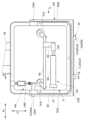
도 1은 본 발명의 일 실시 형태에 있어서의 로드 포트를 구비한 EFEM과 그 주변 장치의 상대 위치 관계를 나타내는 모식적으로 도시하는 측면도.
도 2는 도 1에 도시한 상대 위치 관계를 간략화한 평면도.
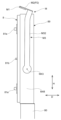
도 3은 동 실시 형태에 있어서의 로드 포트를 일부 생략하여 도시하는 정면도.
도 4는 동 실시 형태에 있어서의 로드 포트를 배면측으로부터 본 도면.
도 5는 동 실시 형태에 있어서의 로드 포트를 일부 생략하여 도시하는 배면도.
도 6은 동 실시 형태에 있어서의 연결 전환 기구의 동작 설명도.
도 7은 종래의 연결 전환 기구를 도 6에 대응하여 도시하는 도면.
도 8은 도 5의 A 방향 화살 표시도.
도 9는 도 5의 B-B선 단면도.
도 10은 매퍼를 매핑 위치에 위치하게 한 상태를 도 9에 대응하여 도시하는 도면.
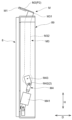
도 11은 동 실시 형태에 있어서의 3축 방향 조정 기구를 실장한 로드 포트의 정면도.
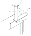
도 12는 도 11의 C 영역을 소정 각도로부터 본 도면.
도 13은 도 11의 C 영역 확대도.
도 14는 도 13의 E-E선 단면도.
도 15는 도 13의 F-F선 단면도.
도 16은 동 실시 형태에 있어서의 로드 포트를 일부 생략하여 도시하는 정면도.
도 17은 도 16의 Q 영역 확대도.
도 18은 도 16의 a-a선 단면도.
도 19는 도 16의 R 영역을 소정 각도로부터 본 도면.
도 20은 도 16의 S 영역을 소정 각도로부터 본 도면.FIG. 1 is a side view schematically illustrating the relative positional relationship between an EFEM having a load port and its peripheral devices according to one embodiment of the present invention.
Figure 2 is a simplified plan view of the relative positional relationship shown in Figure 1.
Figure 3 is a front view showing some of the load ports in the same embodiment omitted.
Figure 4 is a drawing of the load port in the same embodiment as seen from the back side.
Fig. 5 is a rear view showing some of the load ports in the same embodiment omitted.
Figure 6 is a diagram explaining the operation of the connection switching mechanism in the same embodiment.
Fig. 7 is a drawing showing a conventional connection switching mechanism corresponding to Fig. 6.
Figure 8 is a diagram showing the A direction arrow of Figure 5.
Figure 9 is a cross-sectional view taken along line BB of Figure 5.
Fig. 10 is a drawing showing a state in which a mapper is positioned at a mapping position, corresponding to Fig. 9.
Fig. 11 is a front view of a load port equipped with a three-axis direction adjustment mechanism in the same embodiment.
Figure 12 is a drawing of area C of Figure 11 viewed from a certain angle.
Figure 13 is an enlarged view of area C of Figure 11.
Fig. 14 is a cross-sectional view taken along line EE of Fig. 13.
Fig. 15 is a cross-sectional view taken along line FF of Fig. 13.
Fig. 16 is a front view showing some of the load ports in the same embodiment omitted.
Figure 17 is an enlarged view of area Q of Figure 16.
Fig. 18 is a cross-sectional view taken along line aa of Fig. 16.
Figure 19 is a drawing of the R region of Figure 16 viewed from a certain angle.
Figure 20 is a drawing of area S of Figure 16 viewed from a certain angle.
이하, 본 발명의 일 실시 형태를, 도면을 참조하여 설명한다.Hereinafter, one embodiment of the present invention will be described with reference to the drawings.
본 실시 형태에 관한 로드 포트 설치 위치 조정 기구 T는, 로드 포트(1)를 반송실(2)의 벽면(2F)(전방 벽면)에 설치할 때 반송실(2)의 벽면(2F)(전방 벽면)에 대한 로드 포트(1)의 설치 위치를 조정하기 위한 기구이다.The load port installation position adjustment mechanism T according to the present embodiment is a mechanism for adjusting the installation position of the load port (1) with respect to the wall surface (2F) (front wall surface) of the transfer room (2) when the load port (1) is installed on the wall surface (2F) (front wall surface) of the transfer room (2).
로드 포트(1)는, 예를 들어 반도체의 제조 공정에 있어서 사용되며, 도 1 및 도 2에 도시한 바와 같이, 클린룸 내에 있어서, 반송실(2)의 벽면(2F)(전방 벽면)의 일부를 구성하고, 반송실(2)과 FOUP 등의 반송 용기(3) 사이에서 웨이퍼 W 등의 반송 대상물의 출입을 행하기 위한 것이다. 로드 포트(1)는, 반송실(2)과 함께 EFEM(Equipment Front End Module)의 일부를 구성하고, 반송 용기(3)와 반송실(2)의 인터페이스 부분으로서 기능하는 것이다. 본 실시 형태에서는, 반송 용기(3), 로드 포트(1), 반송실(2)이 이 순으로 배열되는 전후 방향 D(도 1 등 참조)에 있어서, 반송 용기 측을 전방으로 정의하고, 반송실 측을 후방으로 정의한다.The load port (1) is used, for example, in a semiconductor manufacturing process, and as illustrated in FIGS. 1 and 2, constitutes a part of a wall surface (2F) (front wall surface) of a transfer room (2) in a clean room, and is for entering and exiting a transfer target object, such as a wafer W, between the transfer room (2) and a transfer container (3), such as a FOUP. The load port (1), together with the transfer room (2), constitutes a part of an EFEM (Equipment Front End Module), and functions as an interface part between the transfer container (3) and the transfer room (2). In the present embodiment, in the front-back direction D (see FIG. 1, etc.) in which the transfer container (3), the load port (1), and the transfer room (2) are arranged in this order, the transfer container side is defined as the front, and the transfer room side is defined as the rear.
반송 용기(3)로서는, 도 1에 모식적으로 도시된 바와 같이, 반출입구(31)를 통해 내부 공간(3S)을 후방으로만 개방 가능한 FOUP 본체(32)와, 반출입구(31)를 개폐 가능한 FOUP 도어(33)를 구비한 FOUP(3)를 들 수 있다. FOUP(3)는, 내부에 다단식 슬롯을 마련하고, 각 슬롯에 반송 대상물인 웨이퍼 W를 수용 가능하게 구성되며, 반출입구(31)를 통해 이들 웨이퍼 W를 출입 가능하게 구성된 기지의 것이다. FOUP 본체(32)의 상향면에는, 반송 용기(3)를 자동으로 반송하는 장치(예를 들어 OHT: Over Head Transport) 등에 파지되는 플랜지부(35)를 마련하고 있다.As a return container (3), as schematically illustrated in Fig. 1, a FOUP (3) may be provided which has a FOUP body (32) whose internal space (3S) can be opened only rearwardly through an entrance/exit (31), and a FOUP door (33) which can open and close the entrance/exit (31). The FOUP (3) is configured to have multi-stage slots provided inside, each slot capable of accommodating a wafer W as a return target, and to allow these wafers W to be entered and exited through the entrance/exit (31). A flange portion (35) is provided on the upper surface of the FOUP body (32) to be held by a device (e.g., OHT: Over Head Transport) that automatically returns the return container (3).
로드 포트(1)는, 도 1 등에 도시한 바와 같이, 반송실(2)의 내부 공간(2S)을 개방하기 위한 개구부(41)가 형성된 판상을 이루는 베이스 프레임(4)과, 베이스 프레임(4)에 대하여 전방으로 돌출시킨 대략 수평 자세로 마련한 적재 테이블(5)과, 외부로부터 반송되어 온 FOUP(3)를 적재 테이블(5) 상에 보유 지지하는 착좌 보유 지지 기구(6)와, 적재 테이블(5) 상에서 FOUP(3)를 착좌 위치와 반송 대상물 전달 위치 사이에서 전후 방향 D로 이동시키는 견인 기구(7)와, 베이스 프레임(4)의 개구부(41)를 개폐하는 로드 포트 도어(8)와, 로드 포트 도어(8)를 반송실(2) 측으로 후퇴한 도어 개방 위치로 이동시킴으로써 베이스 프레임(4)의 개구부(41)를 개방 상태로 하는 도어 개폐 기구(9)를 구비하고 있다.The load port (1), as illustrated in Fig. 1, comprises a base frame (4) formed in a plate shape with an opening (41) for opening the internal space (2S) of the return room (2), a loading table (5) arranged in a substantially horizontal position so as to protrude forward with respect to the base frame (4), a seating and support mechanism (6) for holding and supporting a FOUP (3) that has been returned from the outside on the loading table (5), a traction mechanism (7) for moving the FOUP (3) in the forward and backward direction D between the seating position and the return object transfer position on the loading table (5), a load port door (8) for opening and closing the opening (41) of the base frame (4), and a door opening and closing mechanism (9) for opening the opening (41) of the base frame (4) by moving the load port door (8) to a door opening position retracted toward the return room (2).
베이스 프레임(4)은, 기립 자세로 배치되며, 적재 테이블(5) 상에 적재한 FOUP(3)의 반출입구와 연통할 수 있는 크기의 개구부(41)를 갖는 대략 직사각형 판상의 것이다. 도 1에 베이스 프레임(4)의 개구부(41)를 모식적으로 도시하고 있다. 본 실시 형태의 로드 포트(1)는, 베이스 프레임(4)에 의해 반송실(2)의 벽면(2F)(전방 벽면)의 일부를 구성하고 있다. 베이스 프레임(4)의 하단에는, 캐스터 및 설치 다리부를 갖는 다리부(42)를 마련하고 있다.The base frame (4) is arranged in an upright position and is a substantially rectangular plate having an opening (41) of a size that can communicate with the loading/unloading port of the FOUP (3) loaded on the loading table (5). The opening (41) of the base frame (4) is schematically illustrated in Fig. 1. The load port (1) of the present embodiment constitutes a part of the wall surface (2F) (front wall surface) of the transfer room (2) by the base frame (4). A leg portion (42) having a caster and an installation leg portion is provided at the lower end of the base frame (4).
적재 테이블(5)은, 베이스 프레임(4) 중 높이 방향 중앙보다도 약간 상방 근방의 위치에 대략 수평 자세로 배치되는 수평 기대(50)(지지대)의 상부에 마련되며, FOUP 본체(32)가 베이스 프레임(4)에 대향하는 방향에서 FOUP(3)를 적재 가능한 것이다. 도 3에 도시한 바와 같이, 적재 테이블(5)에는, 상향으로 돌출시킨 복수의 돌기(51)를 마련하고, 이들 돌기(51)를 FOUP(3)의 저면에 형성된 구멍(도시 생략)에 걸림 결합시킴으로써, 적재 테이블(5) 상에 있어서의 FOUP(3)의 위치 결정을 도모하고 있다.The loading table (5) is provided on the upper part of a horizontal base (50) (support) that is arranged in a substantially horizontal position at a position slightly above the center in the height direction of the base frame (4), and is capable of loading a FOUP (3) in a direction in which the FOUP main body (32) faces the base frame (4). As illustrated in Fig. 3, the loading table (5) is provided with a plurality of projections (51) that protrude upward, and by hooking these projections (51) to holes (not illustrated) formed in the bottom surface of the FOUP (3), the positioning of the FOUP (3) on the loading table (5) is facilitated.
착좌 보유 지지 기구(6)는, 적재 테이블(5)에 마련한 로크 갈고리(도시 생략)를, FOUP(3)의 저면에 마련한 피로크부(도시 생략)에 걸어 고정한 로크 상태로 함으로써, FOUP(3)를 적재 테이블(5) 상에 보유 지지하는 것이다. 또한, 본 실시 형태의 로드 포트(1)에서는, 피로크부에 대한 로크 갈고리의 로크 상태를 해제함으로써, FOUP(3)를 적재 테이블(5)로부터 이격 가능한 상태로 할 수 있다.The seating holding support mechanism (6) holds and supports the FOUP (3) on the loading table (5) by fixing the lock hook (not shown) provided on the loading table (5) to a fatigue member (not shown) provided on the bottom of the FOUP (3) in a locked state. In addition, in the load port (1) of the present embodiment, the FOUP (3) can be placed in a state where it can be separated from the loading table (5) by releasing the locked state of the lock hook with respect to the fatigue member.
견인 기구(7)는, 적재 테이블(5) 상에서 FOUP(3)를, FOUP 본체(32)가 로드 포트 도어(8)로부터 소정 거리 이격한 위치인 착좌 위치와, FOUP 본체(32)를 로드 포트 도어(8)에 밀착시키는 위치인 반송 대상물 전달 위치 사이에서 전후 방향 D로 이동시키는 것이다. 견인 기구(7)는, 적재 테이블(5)을 전후 이동시키는 도시하지 않은 슬라이드 레일 등을 사용하여 구성되어 있다. 착좌 보유 지지 기구(6) 및 견인 기구(7)는, 적재 테이블(5)이 구비하는 기구로서 파악할 수도 있다.The traction mechanism (7) moves the FOUP (3) on the loading table (5) in the forward and backward direction D between the seating position, where the FOUP main body (32) is a predetermined distance away from the load port door (8), and the transport object delivery position, where the FOUP main body (32) is brought into close contact with the load port door (8). The traction mechanism (7) is configured using a slide rail (not shown) or the like, which moves the loading table (5) forward and backward. The seating holding and supporting mechanism (6) and the traction mechanism (7) can also be understood as mechanisms provided with the loading table (5).
또한, 도 1에서는, 적재 테이블(5) 상에 있어서의 FOUP(3)의 적재 상태로서, 적재 테이블(5)의 상면에 FOUP(3)의 저면이 접촉하고 있는 상태로서 간략화하여 나타내고 있다. 그러나, 실제로는, 적재 테이블(5)의 상면보다도 상방으로 돌출되어 있는 복수의 돌기(51)가, FOUP(3)의 저면에 형성된 바닥이 있는 구멍에 걸림 결합함으로써 FOUP(3)를 지지하고 있어, 적재 테이블(5)의 상면과 FOUP(3)의 저면은 서로 접촉하지 않고, 적재 테이블(5)의 상면과 FOUP(3)의 저면 사이에 소정의 간극이 형성되도록 규정되어 있다.In addition, in Fig. 1, the loading state of the FOUP (3) on the loading table (5) is simplified as a state in which the bottom surface of the FOUP (3) is in contact with the upper surface of the loading table (5). However, in reality, a plurality of protrusions (51) protruding upward from the upper surface of the loading table (5) support the FOUP (3) by engaging with holes having a bottom formed in the lower surface of the FOUP (3), so that the upper surface of the loading table (5) and the bottom surface of the FOUP (3) do not contact each other, and a predetermined gap is formed between the upper surface of the loading table (5) and the bottom surface of the FOUP (3).
로드 포트 도어(8)는, 베이스 프레임(4)의 개구부(41)를 밀폐하는 완전 폐쇄 위치(도 1 참조)와, 완전 폐쇄 위치보다도 반송실(2) 측으로 후퇴한 도어 개방 위치와, 개구부(41)의 개구 스페이스를 후방으로 완전 개방시키는 완전 개방 위치 사이에서 이동 가능한 것이다. 로드 포트 도어(8)는, 도 3에 도시한 바와 같이, FOUP 도어(33)에 흡착 가능한 흡착부(81a)와, FOUP 도어(33)의 걸림 결합 구멍(래치 홀)에 걸림 결합 가능한 걸림 결합 갈고리(81b)를 구비한 흡착 걸림 결합부(81)를 구비하고, 흡착 걸림 결합부(81)에 의한 FOUP 도어(33)와의 걸림 결합 상태를 유지한 채로 FOUP 도어(33)와 일체적으로 완전 폐쇄 위치, 도어 개방 위치 및 완전 개방 위치의 사이에서 이동 가능하게 구성되어 있다. 본 실시 형태에서는, 완전 폐쇄 위치 및 도어 개방 위치에 위치하게 한 로드 포트 도어(8)의 자세를 동일한 자세로 설정하고 있다. 그리고, 완전 개방 위치와 완전 폐쇄 위치 사이에 있어서의 로드 포트 도어(8)의 이동 경로는, 완전 폐쇄 위치에 있는 로드 포트 도어(8)를 그 높이 위치를 유지한 채로 도어 개방 위치까지 반송실(2) 측으로 이동시킨 경로(수평 경로)와, 도어 개방 위치에 있는 로드 포트 도어(8)를 그 전후 위치를 유지한 채로 완전 개방 위치까지 하방으로 이동시킨 경로(연직 경로)로 이루어진다. 도어 개방 위치에 위치하게 한 로드 포트 도어(8)가 연직 방향 및 수평 방향 중 어느 곳으로도 이동할 수 있도록, 도어 개방 위치에 위치하게 한 로드 포트 도어(8)에 보유 지지되는 FOUP 도어(33)는, 로드 포트 도어(8)와 함께 베이스 프레임(4)보다도 후방의 위치(FOUP 본체(32)로부터 완전히 이격되어, 반송실(2)의 내부 공간(2S)에 배치되는 위치)에 위치하게 된다.The load port door (8) is movable between a completely closed position (see Fig. 1) that seals the opening (41) of the base frame (4), a door open position that is retracted toward the return room (2) from the completely closed position, and a completely open position in which the opening space of the opening (41) is completely opened rearward. As shown in Fig. 3, the load port door (8) is provided with a suction portion (81a) that can be sucked onto the FOUP door (33), and a suction engaging portion (81) that has a engaging hook (81b) that can be hung onto a hanging engaging hole (latch hole) of the FOUP door (33), and is configured to be movable between the completely closed position, the door open position, and the completely open position together with the FOUP door (33) while maintaining the hanging engagement state with the FOUP door (33) by the suction engaging portion (81). In this embodiment, the postures of the load port door (8) positioned in the fully closed position and the door open position are set to the same posture. Then, the movement path of the load port door (8) between the fully opened position and the fully closed position is composed of a path (horizontal path) in which the load port door (8) in the fully closed position is moved toward the door open position to the return room (2) while maintaining its height position, and a path (vertical path) in which the load port door (8) in the door open position is moved downward to the fully opened position while maintaining its forward/backward position. In order for the load port door (8) positioned in the door open position to be able to move in either the vertical or horizontal direction, the FOUP door (33) held and supported by the load port door (8) positioned in the door open position is positioned together with the load port door (8) at a position further rearward than the base frame (4) (a position completely separated from the FOUP main body (32) and arranged in the internal space (2S) of the return room (2).
이와 같은 로드 포트 도어(8)의 이동은, 로드 포트(1)에 마련한 도어 개폐 기구(9)에 의해 실현하고 있다. 도어 개폐 기구(9)는, 로드 포트 도어(8)를 도어 개방 위치나 완전 개방 위치로 이동시킴으로써, 개방 상태로 한 베이스 프레임(4)의 개구부(41)를 통해 FOUP(3)의 내부 공간(3S)을 반송실(2)에 연통시키는 것이다. 도어 개폐 기구(9)는, 예를 들어 로드 포트 도어(8)를 지지하는 지지 프레임(80)(도 4 및 도 5 참조)을 전후 방향 D로 이동 가능하게 지지하는 가동 블록(도시 생략)이나, 가동 블록을 상하 방향 H로 이동 가능하게 지지하는 슬라이드 레일(도시 생략)을 사용하여 구성되며, 액추에이터 등의 구동원(도시 생략)을 작동시켜, 로드 포트 도어(8)를 전후 방향 D 및 상하 방향 H로 이동시키는 것이다. 또한, 전후 이동용의 액추에이터와, 상하 이동용의 액추에이터를 따로따로 구비한 양태여도 되지만, 부품 점수의 삭감이라고 하는 점에서는, 공통의 액추에이터를 구동원으로 하여 로드 포트 도어(8)의 전후 이동 및 상하 이동을 행하는 양태가 우수하다.The movement of the load port door (8) as described above is realized by a door opening/closing mechanism (9) provided in the load port (1). The door opening/closing mechanism (9) connects the internal space (3S) of the FOUP (3) to the transfer room (2) through the opening (41) of the base frame (4) in the open state by moving the load port door (8) to the door opening position or the fully open position. The door opening/closing mechanism (9) is configured using, for example, a movable block (not shown) that supports a support frame (80) (see FIGS. 4 and 5) that supports the load port door (8) so as to be able to move in the forward/backward direction D, or a slide rail (not shown) that supports the movable block so as to be able to move in the up/down direction H, and operates a drive source (not shown) such as an actuator to move the load port door (8) in the forward/backward direction D and the up/down direction H. In addition, it is possible to have an embodiment in which the actuator for forward and backward movement and the actuator for upward and downward movement are provided separately, but in terms of reducing the number of parts, an embodiment in which the forward and backward movement and upward and downward movement of the load port door (8) are performed using a common actuator as a driving source is superior.
본 실시 형태의 로드 포트 도어(8)는, 도 4 및 도 5에 도시한 바와 같이, 흡착 걸림 결합부(81)의 걸림 결합 갈고리(81b)를 작동시켜 FOUP 도어(33)와 FOUP 본체(32)의 걸림 결합 상태(래치 상태)를 해제하여, FOUP 도어(33)를 FOUP 본체(32)로부터 떼어내기 가능한 상태(언래치 상태)로 하는 연결 전환 기구(83)를 구비하고 있다. 연결 전환 기구(83)는, FOUP 도어(33)에 마련한 도시하지 않은 걸림 결합 구멍(래치 홀)에 걸림 결합 가능한 걸림 결합 갈고리(81b)(래치 키)를 소정 각도 범위 내에서 회동시키는 기구이다. 본 실시 형태에서는, 좌우 한 쌍으로 마련한 한 쌍의 걸림 결합 갈고리(81b)를 서로 연결하는 링크 바(84)와, 실린더 로드(851)의 진퇴 동작에 따라서 링크 바(84)를 좌우 폭 방향 W로 이동시키는 실린더(85)를 구비하고, 실린더(85)의 진퇴 동작에 따라서 좌우 한 쌍의 걸림 결합 갈고리(81b)를 동기하여 회전시키는 연결 전환 기구(83)를 적용하고 있다. 또한, 도 4 및 도 5에서는 도어 커버(89)의 일부를 떼어내어 내부가 보이는 상태로 한 도면이다.The load port door (8) of the present embodiment, as shown in FIGS. 4 and 5, is provided with a connection switching mechanism (83) that operates the engagement hook (81b) of the suction engagement portion (81) to release the engagement state (latch state) of the FOUP door (33) and the FOUP body (32), thereby making the FOUP door (33) detachable from the FOUP body (32) (unlatch state). The connection switching mechanism (83) is a mechanism that rotates an engagement hook (81b) (latch key) that can be engaged with a latch hole (not shown) provided in the FOUP door (33) within a predetermined angular range. In this embodiment, a link bar (84) that connects a pair of engaging hooks (81b) provided as a left-right pair, a cylinder (85) that moves the link bar (84) in the left-right width direction W in accordance with the advancing and retreating motion of a cylinder rod (851), and a connecting switching mechanism (83) that rotates the pair of engaging hooks (81b) on the left and right in accordance with the advancing and retreating motion of the cylinder (85) are applied. In addition, FIG. 4 and FIG. 5 are drawings in which a part of a door cover (89) is removed so that the inside is visible.
그리고, 걸림 결합 갈고리(81b)가 FOUP 도어(33)의 걸림 결합 구멍에 걸림 결합한 상태에서, 도 6에 모식도로 도시한 바와 같이, 실린더(85)를 작동시켜 피스톤 로드(851)가 제1 스트로크 위치(1)로부터 제2 스트로크 위치(2)까지 이동함으로써, 걸림 결합 갈고리(81b)가 걸림 결합 구멍에 걸림 결합한 상태인 채로 회동하고, 그 결과, FOUP 도어(33)를 FOUP 본체(32)로부터 떼어내기 가능한 상태(언래치 상태)로 할 수 있다(도 6의 (b) 참조). 그 반대로, 걸림 결합 갈고리(81b)가 FOUP 도어(33)의 걸림 결합 구멍에 걸림 결합한 상태에서, 실린더(85)를 작동시켜 피스톤 로드(851)가 제2 스트로크 위치(2)로부터 제1 스트로크 위치(1)까지 이동하면, 걸림 결합 갈고리(81b)가 걸림 결합 구멍에 걸림 결합한 상태인 채로 회동하고, 그 결과, FOUP 도어(33)를 FOUP 본체(32)에 착탈 불가능한 상태(래치 상태)로 할 수 있다(도 6의 (a) 참조).And, as schematically illustrated in FIG. 6, when the engaging hook (81b) is engaged with the engaging hole of the FOUP door (33), the cylinder (85) is operated so that the piston rod (851) moves from the first stroke position (1) to the second stroke position (2), thereby rotating the engaging hook (81b) while engaging with the engaging hole, and as a result, the FOUP door (33) can be brought into a state (unlatched state) in which it can be separated from the FOUP body (32) (see FIG. 6 (b)). Conversely, when the cylinder (85) is operated so that the piston rod (851) moves from the second stroke position (2) to the first stroke position (1) while the engaging hook (81b) is engaged with the engaging hole of the FOUP door (33), the engaging hook (81b) rotates while being engaged with the engaging hole, and as a result, the FOUP door (33) can be made into a state (latched state) in which it cannot be detached from the FOUP body (32) (see (a) of FIG. 6).
여기서, 로드 포트 도어(8)에 의한 FOUP 도어(33)의 개폐를 확실하게 행할 수 있도록 하기 위해서는, FOUP 도어(33)의 걸림 결합 구멍에 걸림 결합 갈고리(81b)를 확실하게 삽입하여 걸림 결합하고, 그 걸림 결합 상태에 있는 걸림 결합 갈고리(81b)를 회동시킬 필요가 있다. 종래에는, 도 7에 모식적인 기구로서 나타내는 바와 같이, 걸림 결합 갈고리(81b)의 회전 각도를 고정밀도로 조정하는 구성으로서, 실린더(85)의 피스톤 로드(851)의 선단부에 마련한 실린더 브래킷(86)을 피스톤 로드(851)와 일체로 폭 방향 W로 진퇴 이동시킴으로써, 실린더 브래킷(86)에 연결한 링크 바(84)도 일체로 폭 방향 W로 진퇴 이동시키는 구성이 채용되고, 실린더 브래킷(842)의 진퇴 이동 거리를 규정하는 스토퍼 볼트(87)를 로드 포트 도어(8)에 마련하고, 스토퍼 볼트(87)에 실린더 브래킷(86)이 접촉함으로써, 피스톤 로드(851)의 진퇴 이동을 정지시켜, 피스톤 로드(851)의 진퇴 이동에 연동하는 걸림 결합 갈고리(81b)의 회동을 정지시켜 걸림 결합 갈고리(81b)의 회전 각도를 규정하는 구성이 채용되었다. 도 7의 (a), (b)에, 각각 래치 상태, 언래치 상태를 도시한다.Here, in order to reliably open and close the FOUP door (33) by the load port door (8), it is necessary to reliably insert the engaging hook (81b) into the engaging hole of the FOUP door (33) to engage it, and then rotate the engaging hook (81b) in the engaging state. In the past, as shown in a schematic mechanism in Fig. 7, a configuration was adopted in which a cylinder bracket (86) provided at the tip of a piston rod (851) of a cylinder (85) is moved forward and backward together with the piston rod (851) in the width direction W as a single unit, thereby causing a link bar (84) connected to the cylinder bracket (86) to also be moved forward and backward together in the width direction W as a single unit, and a stopper bolt (87) that regulates the distance of movement of the cylinder bracket (842) is provided in the load port door (8), and when the cylinder bracket (86) comes into contact with the stopper bolt (87), the forward and backward movement of the piston rod (851) is stopped, thereby stopping the rotation of the latching hook (81b) linked to the forward and backward movement of the piston rod (851), thereby regulating the rotation angle of the latching hook (81b). Figures 7 (a) and (b) illustrate the latch state and unlatch state, respectively.
이와 같은 종래의 구성에서는, 스토퍼 볼트(841)와 실린더 브래킷(842)이 접촉함으로써 발진하고, 그 발진 물질이 반송실(2) 내에 유입될 가능성이 있었다.In such a conventional configuration, there was a possibility that the stopper bolt (841) and the cylinder bracket (842) would come into contact and generate electricity, and the generated material would flow into the return room (2).
따라서, 본 실시 형태에서는, 도 6에 도시한 바와 같이, 적당한 시일 구조에 의해 높은 기밀성이 유지되는 실린더(85)의 내부에 스토퍼 볼트(87)를 마련하고 있다. 그리고, 도 6의 (b)에 도시한 바와 같이, 이 스토퍼 볼트(87)에 피스톤 로드(851)의 기단(엔드단)이 접촉함으로써, 피스톤 로드(851)의 진퇴 이동(구체적으로는 후퇴 방향으로의 이동)을 정지시켜, 피스톤 로드(851)의 진퇴 이동에 연동하는 걸림 결합 갈고리(81b)의 회동을 정지시켜 걸림 결합 갈고리(81b)의 회전 각도를 규정하도록 구성하고 있다. 특히 본 실시 형태에서는, 스토퍼 볼트(87)로서 어저스터 볼트를 적용하고, 실린더(85)의 내부에 있어서의 어저스터 볼트의 선단 위치(피스톤 로드(851)와 접촉하는 위치)를 조정 가능하게 구성하고 있다. 또한, 실린더(85)의 내부에 있어서의 선단 측의 소정 위치에 피스톤 로드(851)의 기단부가 접촉하는 충격 흡수재(88)(쿠션)를 마련함으로써, 피스톤 로드(851)의 전진 방향으로의 이동을 규제할 수 있다. 또한, 스토퍼 볼트(87)의 소정 위치에 충격 흡수재(88)(쿠션)를 마련함으로써, 피스톤 로드(851)의 전진 방향으로의 이동을 규제하도록 구성할 수도 있다.Therefore, in this embodiment, as illustrated in FIG. 6, a stopper bolt (87) is provided inside a cylinder (85) in which high sealing is maintained by an appropriate seal structure. Then, as illustrated in FIG. 6 (b), when the base end (end end) of the piston rod (851) comes into contact with the stopper bolt (87), the forward and backward movement (specifically, the movement in the backward direction) of the piston rod (851) is stopped, thereby stopping the rotation of the engaging claw (81b) linked to the forward and backward movement of the piston rod (851), thereby regulating the rotation angle of the engaging claw (81b). In particular, in this embodiment, an adjuster bolt is applied as the stopper bolt (87), and the tip position of the adjuster bolt (the position in contact with the piston rod (851)) inside the cylinder (85) is configured to be adjustable. In addition, by providing a shock absorber (88) (cushion) at a predetermined position on the tip side inside the cylinder (85) with which the base end of the piston rod (851) comes into contact, the movement of the piston rod (851) in the forward direction can be regulated. In addition, by providing a shock absorber (88) (cushion) at a predetermined position of the stopper bolt (87), the movement of the piston rod (851) in the forward direction can be regulated.
이와 같은 구성에 의하면, 실린더(85)의 구동 시에 실린더(85)의 내부에서 파츠끼리의 접촉이 발생하지만, 실린더(85)의 내부는 적당한 시일 구조에 의해 높은 기밀성이 유지되고 있기 때문에, 실린더(85)의 내부에서 발생한 분진을 실린더(85)의 내부에 머물게 해 둘 수 있다. 그 결과, 실린더(85)의 내부에서 발생한 분진이 실린더(85)의 외부로 방출되는 사태를 방지·억제할 수 있다. 게다가, 종래의 구성과 비교하여, 실린더(85)의 외부에 별도로 전용의 스토퍼 볼트를 마련할 필요가 없기 때문에, 구성의 간소화 및 부품 점수의 삭감에 기여하여, 비용 절감을 도모할 수 있다.With this configuration, when the cylinder (85) is driven, contact between parts occurs inside the cylinder (85), but since the inside of the cylinder (85) is maintained with high airtightness by an appropriate seal structure, dust generated inside the cylinder (85) can be kept inside the cylinder (85). As a result, dust generated inside the cylinder (85) can be prevented and suppressed from being released outside the cylinder (85). In addition, compared to the conventional configuration, since there is no need to separately provide a dedicated stopper bolt outside the cylinder (85), this contributes to simplification of the configuration and reduction of the number of parts, thereby helping to reduce costs.
또한, 본 실시 형태에 관한 로드 포트는, 도어 개폐 기구(9)에 의해 베이스 프레임(4)의 개구부(41)를 개방 상태로 한 상태에 있어서, 반송 대상물 전달 위치에 있는 FOUP(3) 내의 각 슬롯(34)에 있어서의 웨이퍼 W의 유무를 포함하는 웨이퍼 W의 적재 상태에 관한 정보를 매핑하는 매핑 기구 M을 구비하고 있다.In addition, the load port according to the present embodiment is equipped with a mapping mechanism M that maps information on the loading status of wafers W, including the presence or absence of wafers W in each slot (34) in the FOUP (3) at the transfer target object delivery position, when the opening (41) of the base frame (4) is opened by the door opening/closing mechanism (9).
매핑 기구 M은, 도 1, 도 4, 도 5 및 도 8 등에 도시한 바와 같이, FOUP(3) 내에 마련한 다단식 슬롯에 의해 높이 방향 H로 다단상으로 수납된 반송 대상물 W의 유무를 검출 가능한 매핑 센서 M1(송신기 M11, 수신기 M12)을 선단부에 갖는 매퍼 M2와, 매퍼 M2를 지지하는 매핑 암 M3(매핑 이동부)을 구비하여, FOUP(3) 내에 있어서의 반송 대상물 W의 유무나 수납 자세를 검출 가능한 것이다.As shown in FIG. 1, FIG. 4, FIG. 5, and FIG. 8, the mapping mechanism M comprises a mapper M2 having a mapping sensor M1 (transmitter M11, receiver M12) at the tip end capable of detecting the presence or absence of a return object W stored in multiple stages in the height direction H by means of multi-stage slots provided in the FOUP (3), and a mapping arm M3 (mapping moving part) supporting the mapper M2, so as to detect the presence or absence of a return object W and the storage posture in the FOUP (3).
매퍼 M2는, 도 8 및 도 9(도 8, 도 9는 각각 도 5의 A 방향 화살 표시도, B-B선 단면도임)에 도시한 바와 같이, 매핑 암 M3의 소정 개소로부터 전방으로 돌출되는 형태로 폭 방향 W로 소정 거리 이격되어 좌우 한 쌍으로 병설되며, 선단부에 매핑 센서 M1을 설치한 것이다. 또한, 도 8 및 도 9에서는, 절단면을 나타내는 해칭(평행 사선)을 생략하였다. 매핑 센서 M1은, 신호인 빔(선광)을 발하는 송신기 M11(발 광 센서)과, 송신기 M11로부터 발해진 신호를 수신하는 수신기 M12(수광 센서)로 구성된다. 또한, 매핑 센서 M1을 송신기와, 송신기로부터 발해진 선광을 송신기를 향하여 반사하는 반사부에 의해 구성하는 것도 가능하다. 이 경우, 송신기는, 수신기로서의 기능도 갖는다. 광축을 좌우의 수평 방향으로 향하게 한 매핑 센서 M1(M11, M12)이 매핑 처리 시에 검지 대상인 반송 대상물 W에 간섭하지 않도록, 매핑 센서 M1(M11, M12)끼리의 좌우의 스팬을 반송 대상물 W의 평면 치수에 따라서 적당한 값으로 설정하고 있다.The mapper M2, as illustrated in FIGS. 8 and 9 (FIGS. 8 and 9 are an A direction arrow diagram and a B-B line cross-sectional diagram of FIG. 5, respectively), is arranged in a pair on the left and right sides, protruding forward from a predetermined location of the mapping arm M3 and spaced apart from each other in the width direction W by a predetermined distance, and has a mapping sensor M1 installed at the tip. In addition, hatching (parallel diagonal lines) indicating the cross-section is omitted in FIGS. 8 and 9. The mapping sensor M1 is composed of a transmitter M11 (light-emitting sensor) that emits a signal beam (light beam) and a receiver M12 (light-receiving sensor) that receives a signal emitted from the transmitter M11. In addition, the mapping sensor M1 can also be composed of a transmitter and a reflector that reflects the light beam emitted from the transmitter toward the transmitter. In this case, the transmitter also has a function as a receiver. To prevent the mapping sensor M1 (M11, M12) whose optical axis is oriented in the horizontal direction of the left and right from interfering with the return target W, which is the detection target during mapping processing, the left and right spans between the mapping sensors M1 (M11, M12) are set to an appropriate value according to the plane dimensions of the return target W.
매핑 암 M3은, 전후 방향 D에 있어서의 매퍼 M2의 위치를, 도 10에 도시한 위치, 즉, 개방 상태에 있는 개구부(41)를 통해 FOUP(3)에 웨이퍼 W가 수용되어 있는 것을 매핑 센서 M1로 검지 가능한 매핑 위치(P1)와, 도 8 및 도 9에 도시한 위치, 즉, FOUP(3)에 웨이퍼 W가 수용되어 있는 것을 매핑 센서 M1로 검지 불가능한 웨이퍼 매핑 불능 위치(P2) 사이에서 이동시키는 것이다. 또한, 도 10은 매퍼 M2를 매핑 위치(P1)에 위치하게 한 상태를 도 9에 대응하여 도시하는 도면이다.The mapping arm M3 moves the position of the mapper M2 in the forward-backward direction D between a mapping position (P1) where the wafer W is accommodated in the FOUP (3) through the opening (41) in the open state, as shown in Fig. 10, and a wafer mapping impossible position (P2) where the wafer W is accommodated in the FOUP (3) cannot be detected by the mapping sensor M1, as shown in Figs. 8 and 9. In addition, Fig. 10 is a drawing corresponding to Fig. 9 showing a state where the mapper M2 is positioned at the mapping position (P1).
본 실시 형태의 매핑 암 M3은, 도 3 및 도 4에 도시한 바와 같이, 상부 프레임부 M31과, 상부 프레임부 M31의 양단으로부터 각각 하방으로 연장되는 좌우 한 쌍의 측부 프레임부 M32를 일체 또는 일체적으로 갖는 하향 コ자상을 이루고, 각 측부 프레임부 M32의 하단부를 회전 중심축으로 하여 소정 각도 범위 내에서 회동함으로써, 매퍼 M2의 위치를 매핑 위치(P1)와 웨이퍼 매핑 불능 위치(P2) 사이에서 이동시키는 것이다.As illustrated in FIGS. 3 and 4, the mapping arm M3 of the present embodiment has a downward U-shape including an upper frame portion M31 and a pair of left and right side frame portions M32 extending downward from each end of the upper frame portion M31, integrally or integrally, and rotates within a predetermined angular range about the lower end of each side frame portion M32 as a center of rotation, thereby moving the position of the mapper M2 between a mapping position (P1) and a wafer mapping-impossible position (P2).
특히, 본 실시 형태에서는, 각 측부 프레임부 M32의 하단부를, 로드 포트 도어(8)의 주변 파츠를 반송실(2) 측으로부터 피복하는 도어 커버(89)의 측면에 회동 가능하게 설치하고 있다. 여기서, 본 실시 형태의 매핑 기구 M은, 매핑 암 M3과 도어 커버(89)의 설치부에 있어서의 피봇점을 중심으로 매핑 암 M3 전체를 틸팅시키는 틸팅 기구 M4를 구비하고 있다. 틸팅 기구 M4는, 도 9 및 도 10에 도시한 바와 같이, 매핑 암 구동용 실린더 M41과, 매핑 암 구동용 실린더 M41의 선단부(실린더 로드의 선단부)에 일단부(하단부)를 연결한 매핑 암 구동용 크랭크 M42와, 매핑 암 구동용 크랭크 M42의 타단부(상단부)에 연결한 매핑 암 피봇축부 M43(피봇점에 상당)을 구비한 것이다. 본 실시 형태에서는, 매핑 암 구동용 실린더 M41 및 매핑 암 구동용 크랭크 M42를 도어 커버(89)의 내부 공간에 배치하고, 또한, 매핑 암 피봇축부 M43 중 매핑 암 M3의 하단부(측부 프레임부 M32의 하단부)에 고정하는 일단부 측의 소정 영역을 제외한 대부분을 도어 커버(89)의 내부 공간에 배치하고 있다. 매핑 암 피봇축부 M43은, 긴 변 방향과 일치하는 축 방향을 로드 포트(1)의 폭 방향 W로 연신되는 자세로 배치되고, 일단부에 매핑 암 M3의 하단부(측부 프레임부 M32의 하단부)을 일체 회전 가능하게 고정하고, 타단부에 매핑 암 구동용 크랭크 M42를 일체 회전 가능하게 고정한 것이다. 본 실시 형태에서는, 매핑 암 피봇축부 M43의 설치 위치를, 측부 프레임부 M32의 높이 방향 중앙 위치보다도 약간 하방의 위치(로드 포트 도어(8)의 높이 방향 중앙에 가까운 위치)로 설정하고 있다(도 5 등 참조).In particular, in this embodiment, the lower part of each side frame part M32 is rotatably installed on the side of the door cover (89) that covers the peripheral parts of the load port door (8) from the transfer room (2) side. Here, the mapping mechanism M of this embodiment is provided with a tilting mechanism M4 that tilts the entire mapping arm M3 about a pivot point at the installation part of the mapping arm M3 and the door cover (89). As shown in FIGS. 9 and 10, the tilting mechanism M4 is provided with a mapping arm driving cylinder M41, a mapping arm driving crank M42 having one end (lower end) connected to the tip end (tip end of the cylinder rod) of the mapping arm driving cylinder M41, and a mapping arm pivot shaft part M43 (corresponding to a pivot point) connected to the other end (upper end) of the mapping arm driving crank M42. In this embodiment, the cylinder M41 for driving the mapping arm and the crank M42 for driving the mapping arm are arranged in the internal space of the door cover (89), and further, most of the area except for a predetermined area on the side of one end of the mapping arm pivot shaft portion M43 that is fixed to the lower end of the mapping arm M3 (the lower end of the side frame portion M32) is arranged in the internal space of the door cover (89). The mapping arm pivot shaft portion M43 is arranged in a posture in which the axial direction that matches the long side direction extends in the width direction W of the load port (1), and the lower end of the mapping arm M3 (the lower end of the side frame portion M32) is fixed to one end so as to be able to rotate integrally, and the crank M42 for driving the mapping arm is fixed to the other end so as to be able to rotate integrally. In this embodiment, the installation position of the mapping arm pivot shaft portion M43 is set to a position slightly lower than the central position in the height direction of the side frame portion M32 (a position close to the central position in the height direction of the load port door (8)) (see Fig. 5, etc.).
이와 같은 틸팅 기구 M4(매핑 암 구동 기구)에 의하면, 매핑 암 구동용 실린더 M41의 진퇴 동작에 연동하여 매핑 암 구동용 크랭크 M42가 제1 포지션(1)과 제2 포지션(2) 사이에서 이동한다. 도 10에 도시한 바와 같이, 매핑 암 구동용 크랭크 M42가 제1 포지션(1)에 있는 경우, 매퍼 M2를 매핑 위치(P1)에 위치하게 할 수 있다. 한편, 도 9에 도시한 바와 같이, 매핑 암 구동용 실린더 M41을 작동시켜 매핑 암 구동용 크랭크 M42를 제1 포지션(1)으로부터 제2 포지션(2)으로 이동시키면, 그 이동에 연동하여 매핑 암 피봇축부 M43이 회전하고, 그 회전 각도에 따른 분만큼 매핑 암 M3이 매핑 암 피봇축부 M43을 피봇축으로 하여 틸팅하여, 매퍼 M2를 매핑 위치(P1)로부터 웨이퍼 매핑 불능 위치(P2)로 전환할 수 있다.According to the tilting mechanism M4 (mapping arm driving mechanism), the mapping arm driving crank M42 moves between the first position (1) and the second position (2) in conjunction with the advancing and retreating motion of the mapping arm driving cylinder M41. As illustrated in FIG. 10, when the mapping arm driving crank M42 is at the first position (1), the mapper M2 can be positioned at the mapping position (P1). On the other hand, as illustrated in FIG. 9, when the mapping arm driving cylinder M41 is operated to move the mapping arm driving crank M42 from the first position (1) to the second position (2), the mapping arm pivot shaft part M43 rotates in conjunction with the movement, and the mapping arm M3 tilts about the mapping arm pivot shaft part M43 as a pivot axis by an amount according to the rotation angle, so that the mapper M2 can be switched from the mapping position (P1) to the wafer mapping non-mapping position (P2).
본 실시 형태에서는, 매핑 암 구동용 크랭크 M42가 제1 포지션(1)에 있는 것을 검지하는 제1 포지션 검지 센서(도시 생략)와, 매핑 암 구동용 크랭크 M42가 제2 포지션(2)에 있는 것을 검지하는 제2 포지션 검지 센서(도시 생략)를 구비하고, 이들 검출 신호에 기초하여 매핑 암 구동용 실린더 M41의 구동, 나아가서는 틸팅 기구 M4에 의한 매핑 암 M3의 틸팅을 제어함으로써, 매퍼 M2의 위치를 매핑 위치(P1), 웨이퍼 매핑 불능 위치(P2)에 각각 정확하게 위치하게 할 수 있다. 또한, 각 측부 프레임부 M32의 하단부의 하방에는 카운터웨이트(도시 생략)를 마련하여, 틸팅 기구 M4에 의한 매핑 암 M3의 틸팅 동작의 안정화를 도모하고 있다. 본 실시 형태에 있어서의 매핑 암 M3은, 도어 커버(89)와 일체로 전후 방향 및 상하 방향으로 동작하는 것이며, 또한 도어 개폐 기구(9)와는 독립적으로 틸팅 기구 M4에 의해 동작하는 것이다.In this embodiment, a first position detection sensor (not shown) that detects that the mapping arm driving crank M42 is in the first position (1) and a second position detection sensor (not shown) that detects that the mapping arm driving crank M42 is in the second position (2) are provided, and based on these detection signals, the driving of the mapping arm driving cylinder M41 and, further, the tilting of the mapping arm M3 by the tilting mechanism M4 are controlled, whereby the position of the mapper M2 can be accurately positioned at the mapping position (P1) and the wafer mapping impossible position (P2), respectively. In addition, a counterweight (not shown) is provided below the lower part of each side frame portion M32 to attempt to stabilize the tilting operation of the mapping arm M3 by the tilting mechanism M4. In this embodiment, the mapping arm M3 operates in the forward/backward direction and up/down direction integrally with the door cover (89), and also operates independently of the door opening/closing mechanism (9) by the tilting mechanism M4.
도어 커버(89)의 내부 공간은 밀폐 상태로 유지되고 있다. 따라서, 매핑 암 구동용 실린더 M41의 진퇴 동작 시에, 매핑 암 구동용 실린더 M41과 매핑 암 구동용 크랭크 M42의 접촉 부위나, 매핑 암 구동용 크랭크 M42와 매핑 암 피봇축부 M43의 접촉 부위에서 파티클이 발생하였다고 해도, 도어 커버(89)의 내부 공간에 가둘 수 있다. 그 결과, 이들 파티클이 도어 커버(89)의 내부 공간으로부터 반송실(2)의 내부 공간(2S)으로 배출되는 사태를 방지·억제할 수 있다. 또한, 종래에는, 매핑 암의 회전 중심축이 도어 커버(89)보다도 하방의 위치, 예를 들어 로드 포트 도어(8)를 지지하는 지지 프레임(80)의 소정 위치에 설정되고, 틸팅 기구도 그 주변에 배치되었다. 따라서, 매핑 암 구동용 실린더와 매핑 암 구동용 크랭크의 접촉 부위나, 매핑 암 구동용 크랭크와 매핑 암 피봇축부의 접촉 부위에서 발생한 파티클이 반송실의 내부 공간으로 배출되거나, 반송실의 내부 공간을 향하여 날아 올라갈 우려가 있었다. 한편, 상술한 본 실시 형태의 틸팅 기구 M4에 의해 매핑 암 M3을 틸팅·구동시키는 구성에 의하면, 이와 같은 종래의 문제점을 해소할 수 있다.The internal space of the door cover (89) is maintained in a sealed state. Therefore, even if particles are generated at the contact site between the mapping arm driving cylinder M41 and the mapping arm driving crank M42, or the contact site between the mapping arm driving crank M42 and the mapping arm pivot shaft part M43 during the forward and backward movement of the mapping arm driving cylinder M41, they can be confined in the internal space of the door cover (89). As a result, it is possible to prevent and suppress the situation in which these particles are discharged from the internal space of the door cover (89) into the internal space (2S) of the transfer room (2). In addition, conventionally, the rotational center axis of the mapping arm is set at a position lower than the door cover (89), for example, at a predetermined position of the support frame (80) supporting the load port door (8), and the tilting mechanism is also arranged around it. Accordingly, there was a concern that particles generated at the contact portion between the mapping arm driving cylinder and the mapping arm driving crank, or at the contact portion between the mapping arm driving crank and the mapping arm pivot shaft, would be discharged into the internal space of the return room or fly up toward the internal space of the return room. Meanwhile, according to the configuration of tilting and driving the mapping arm M3 by the tilting mechanism M4 of the present embodiment described above, such conventional problems can be resolved.
또한, 본 실시 형태의 틸팅 기구 M4에 의해 매핑 암 M3을 틸팅·구동시키는 구성에 의하면, 매핑 암의 회전 중심축을 도어 커버(89)보다도 하방의 위치, 예를 들어 로드 포트 도어(8)를 지지하는 지지 프레임(80)의 소정 위치에 설정한 종래의 양태와 비교하여, 매핑 암 M3의 암 길이(매핑 암 M3의 회전 중심축 M43으로부터 매핑 암 M3의 상단인 상부 프레임부 M31까지의 길이)가 짧아지기 때문에, 종래의 구성과 비교하여 매핑 암 M3의 동작 시의 진동을 억제할 수 있어, 매핑 정밀도의 향상에 기여한다.In addition, according to the configuration of tilting and driving the mapping arm M3 by the tilting mechanism M4 of the present embodiment, compared to the conventional embodiment in which the rotation center axis of the mapping arm is set at a position lower than the door cover (89), for example, at a predetermined position of the support frame (80) supporting the load port door (8), the arm length of the mapping arm M3 (the length from the rotation center axis M43 of the mapping arm M3 to the upper frame portion M31, which is the upper end of the mapping arm M3) is shortened, so that vibration during operation of the mapping arm M3 can be suppressed compared to the conventional configuration, thereby contributing to improvement of mapping precision.
본 실시 형태의 로드 포트(1)는, 적재 테이블(5)에 마련되며 FOUP(3)의 저면 측으로부터 당해 FOUP(3) 내에 질소 가스나 불활성 가스 또는 드라이 에어 등의 적절히 선택된 기체인 환경 가스(퍼지 가스라고도 칭해지며, 본 실시 형태에서는 주로 질소 가스나 드라이 에어를 사용하고 있음)를 주입하여, FOUP(3) 내의 기체 분위기를 환경 가스로 치환 가능한 보텀 퍼지부를 구비할 수 있다. 보텀 퍼지부는, 적재 테이블(5) 상의 소정 개소에 복수 마련된 도시하지 않은 노즐을 주체로 하여 이루어지며, 복수의 노즐을, 소정의 환경 가스를 주입하는 보텀 퍼지 주입용 노즐이나, FOUP(3) 내의 기체 분위기를 배출하는 보텀 퍼지 배출용 노즐로서 기능시키고 있다. 이들 복수의 노즐은, FOUP(3)의 저부에 마련한 도시하지 않은 주입구(주입용 포트) 및 배출구(배기용 포트)에 끼워 맞춘 상태에서 연결 가능한 것이다. 주입구를 통해 보텀 퍼지 주입용 노즐로부터 FOUP(3)의 내부 공간(3S)에 환경 가스를 공급하고, 배출구를 통해 보텀 퍼지 배출용 노즐로부터 FOUP(3)의 내부 공간(3S)의 기체 분위기(이 기체 분위기는, 퍼지 처리 실행 개시로부터 소정 시간까지는 공기나 공기 이외의 청정도가 낮은 환경 가스이며, 당해 소정 시간 경과 후에는 FOUP(3)의 내부 공간(3S)에 충전된 청정도가 높은 환경 가스임)를 배출함으로써, 퍼지 처리를 행하는 것이 가능하다.The load port (1) of the present embodiment is provided on the loading table (5) and can be provided with a bottom purge section capable of replacing the gaseous atmosphere inside the FOUP (3) with the environmental gas (also referred to as purge gas, and in the present embodiment, mainly nitrogen gas or dry air is used) that is an appropriately selected gas such as nitrogen gas, an inert gas, or dry air from the bottom side of the FOUP (3). The bottom purge section is mainly formed by a plurality of nozzles (not shown) provided at predetermined locations on the loading table (5), and the plurality of nozzles function as bottom purge injection nozzles that inject a predetermined environmental gas, or bottom purge discharge nozzles that discharge the gaseous atmosphere inside the FOUP (3). These plurality of nozzles can be connected in a state where they are fitted into an injection port (injection port) and an exhaust port (exhaust port) (not shown) provided at the bottom of the FOUP (3). It is possible to perform a purge process by supplying environmental gas into the internal space (3S) of the FOUP (3) from a bottom purge injection nozzle through an inlet, and discharging a gaseous atmosphere (this gaseous atmosphere is air or an environmental gas with a low degree of cleanliness other than air until a predetermined time from the start of purge process execution, and is an environmental gas with a high degree of cleanliness filled in the internal space (3S) of the FOUP (3)) of the internal space (3S) of the FOUP (3) from a bottom purge discharge nozzle through an outlet.
이와 같은 로드 포트(1)는, 내부에 반송 로봇(21)을 구비한 반송실(2)과 함께 EFEM을 구성한다. 본 실시 형태에서는, 도 2에 도시한 바와 같이, 반송실(2)의 전방면(전방 벽면)(2F)에 로드 포트(1)를 복수(예를 들어 3대) 나란히 배치하고 있다. EFEM의 작동은, 로드 포트(1)의 컨트롤러(도 2에 도시한 제어부(1C))나, EFEM 전체의 컨트롤러(도 1에 도시한 제어부 C)에 의해 제어된다.Such a load port (1) constitutes an EFEM together with a transfer room (2) equipped with a transfer robot (21) inside. In this embodiment, as shown in Fig. 2, a plurality of load ports (1) (for example, three) are arranged side by side on the front surface (front wall surface) (2F) of the transfer room (2). The operation of the EFEM is controlled by a controller of the load port (1) (control unit (1C) shown in Fig. 2) or a controller of the entire EFEM (control unit C shown in Fig. 1).
반송실(2)의 내부 공간(2S)에는, 웨이퍼 W 등의 반송 대상물을 로드 포트(1) 상의 FOUP(3)와 처리실 R 사이에서 반송 가능한 반송 로봇(21)이 마련되어 있다. 반송 로봇(21)은, 도 1 및 도 2에 도시한 바와 같이, 예를 들어 복수의 링크 요소를 서로 수평 선회 가능하게 연결하고, 선단부에 반송 대상물 파지부(211)(핸드)를 마련한 암(212)과, 암(212)의 기단부를 구성하는 암 베이스를 선회 가능하게 지지하고 또한 반송실(2)의 폭 방향 W(로드 포트(1)의 병렬 방향)로 주행하는 주행부를 구비한 것이다. 반송 로봇(21)은, 암 길이가 최소로 되는 절첩 상태와, 암 길이가 절첩 상태 시보다도 길어지는 신장 상태 사이에서 형상이 변하는 링크 구조(다관절구조)를 갖는다. 암(212)의 선단에, 개별로 제어 가능한 복수의 핸드(211)를 높이 방향으로 다단형으로 마련한 반송 로봇(21)을 적용할 수 있다.In the internal space (2S) of the return room (2), a return robot (21) capable of returning a return target object, such as a wafer W, between a FOUP (3) on a load port (1) and a processing room R is provided. As illustrated in FIGS. 1 and 2, the return robot (21) is provided with, for example, an arm (212) in which a plurality of link elements are connected to each other so as to be capable of horizontal rotation, and which has a return target object gripping portion (211) (hand) provided at a tip end, and a driving portion that supports an arm base constituting a base end of the arm (212) so as to be capable of rotation and also drives in the width direction W of the return room (2) (parallel direction of the load port (1)). The return robot (21) has a link structure (multi-joint structure) whose shape changes between a folded state in which the arm length is minimum and an extended state in which the arm length becomes longer than in the folded state. At the tip of the arm (212), a return robot (21) having a plurality of individually controllable hands (211) arranged in a multi-stage configuration in the height direction can be applied.
반송실(2)은, 로드 포트(1) 및 처리실 R이 접속됨으로써, 내부 공간(2S)이 대략 밀폐된 상태가 되도록 구성하고 있다. 반송실(2)의 내부 공간(2S)에는, 도 1에 도시한 바와 같이, 상방으로부터 하방을 향하는 기류인 다운 플로우를 형성하고 있다. 따라서, 반송실(2)의 내부 공간(2S)에 웨이퍼 W의 표면을 오염시키는 파티클이 존재한 경우라도, 다운 플로우에 의해 파티클을 하방으로 밀어내려, 반송 중인 웨이퍼 W의 표면으로의 파티클의 부착을 억제하는 것이 가능해진다. 도 1에는, 다운 플로우를 형성하고 있는 반송실(2) 내의 기체의 흐름을 화살표로 모식적으로 나타내고 있다. 반송실(2)의 측면이나 반송실(2)의 내부 공간(2S)에 버퍼 스테이션, 얼라이너 등의 적절한 스테이션을 배치한 EFEM을 구성하는 것도 가능하다.The return room (2) is configured so that the internal space (2S) is substantially sealed by connecting the load port (1) and the processing room R. As shown in Fig. 1, a downflow, which is an airflow that flows from the upper side to the lower side, is formed in the internal space (2S) of the return room (2). Therefore, even if there are particles that contaminate the surface of the wafer W in the internal space (2S) of the return room (2), it is possible to suppress the attachment of the particles to the surface of the wafer W being returned by pushing the particles downward by the downflow. Fig. 1 schematically shows the flow of gas in the return room (2) that forms the downflow with arrows. It is also possible to configure an EFEM in which appropriate stations, such as a buffer station and an aligner, are arranged on the side of the return room (2) or in the internal space (2S) of the return room (2).
본 실시 형태에서는, 반송실(2) 중 로드 포트(1)를 배치한 벽면(2F)(전방 벽면)에 대향하는 벽면(2B)(후방 벽면)에, 처리실 R(반도체 처리 장치)을 폭 방향 W로 복수(도시예에서는 3실) 나란히 배치하고, 각 처리실 R 내에서 각각 다른 적절한 처리가 실시되도록 구성하고 있다. 반도체 제조 공정의 중간 공정이나 후공정에서 행하는 처리예로서, 백 랩 처리 공정, 웨이퍼 적층 처리 공정, 다이싱 처리 공정 등을 들 수 있다. 또한, 처리실 R의 작동은, 처리실 R의 컨트롤러(도 1에 도시한 제어부 RC)에 의해 제어된다. 여기서, 처리실 R 전체의 컨트롤러(제어부 RC)나, EFEM 전체의 컨트롤러(제어부 C)는, 로드 포트(1)의 제어부(1C)의 상위 컨트롤러이다.In this embodiment, a plurality of processing rooms R (semiconductor processing devices) (three rooms in the illustrated example) are arranged side by side in the width direction W on a wall surface (2B) (rear wall surface) facing a wall surface (2F) (front wall surface) on which a load port (1) is arranged in a return room (2), and different appropriate processing is performed in each processing room R. Examples of processing performed in an intermediate process or a post-process of a semiconductor manufacturing process include a back lap processing process, a wafer lamination processing process, a dicing processing process, and the like. In addition, the operation of the processing room R is controlled by a controller of the processing room R (control unit RC illustrated in Fig. 1). Here, the controller of the entire processing room R (control unit RC) or the controller of the entire EFEM (control unit C) is an upper controller of the control unit (1C) of the load port (1).
각 처리실 R의 내부 공간 RS, 반송실(2)의 내부 공간(2S) 및 각 로드 포트(1) 상에 적재되는 FOUP(3)의 내부 공간(3S)은 고청정도로 유지된다. 한편, 로드 포트(1)를 배치한 공간, 환언하면 처리실 외, EFEM 외는 비교적 저청정도가 된다. 또한, 도 1 및 도 2는, 로드 포트(1) 및 반송실(2)의 상대 위치 관계, 및 이들 로드 포트(1) 및 반송실(2)을 구비한 EFEM과, 처리실 R의 상대 위치 관계를 모식적으로 도시한 도면이다.The internal space RS of each processing room R, the internal space (2S) of the return room (2), and the internal space (3S) of the FOUPs (3) loaded on each load port (1) are maintained at a high level of cleanliness. On the other hand, the space where the load port (1) is arranged, in other words, outside the processing room and outside the EFEM, has a relatively low level of cleanliness. In addition, FIG. 1 and FIG. 2 are drawings schematically showing the relative positional relationship between the load port (1) and the return room (2), and the relative positional relationship between the EFEM equipped with these load ports (1) and the return room (2), and the processing room R.
그리고, 본 실시 형태에 관한 로드 포트 설치 위치 조정 기구 T는, 로드 포트(1)를 반송실(2)의 벽면(전방 벽면(2F))에 배치하여 설치할 때, 반송실(2)의 벽면(2F)에 대한 로드 포트(1)의 설치 위치를 조정하기 위한 기구이다.And, the load port installation position adjustment mechanism T according to the present embodiment is a mechanism for adjusting the installation position of the load port (1) with respect to the wall surface (2F) of the transfer room (2) when the load port (1) is installed by arranging it on the wall surface (front wall surface (2F)) of the transfer room (2).
로드 포트 설치 위치 조정 기구 T는, 도 11에 도시한 바와 같이, 반송실(2)의 벽면(전방 벽면(2F))에 대한 로드 포트(1)의 폭 방향 W(좌우 방향)의 위치를 조정하는 X축 방향 조정부 T1과, 반송실(2)의 벽면(전방 벽면(2F))에 대한 로드 포트(1)의 두께 방향 D(전후 방향, 깊이 방향)의 위치(올려다보는 구도의 위치)를 조정하는 Y축 방향 조정부 T2와, 반송실(2)의 벽면(전방 벽면(2F))에 대한 로드 포트(1)의 높이 방향 H(상하 방향)의 위치를 조정하는 Z축 방향 조정부 T3을 구비하고, 이들 3축 방향의 각 조정부(X축 방향 조정부 T1, Y축 방향 조정부 T2, Z축 방향 조정부 T3)를 집약한 3축 방향 조정 기구 T4를 베이스 프레임(4)의 상부 코너부에 배치한 것이다.The load port installation position adjustment mechanism T, as illustrated in Fig. 11, comprises an X-axis adjustment part T1 for adjusting the position in the width direction W (left-right direction) of the load port (1) with respect to the wall surface (front wall surface (2F)) of the transfer room (2), a Y-axis adjustment part T2 for adjusting the position (position when looking up) in the thickness direction D (front-back direction, depth direction) of the load port (1) with respect to the wall surface (front wall surface (2F)) of the transfer room (2), and a Z-axis adjustment part T3 for adjusting the position in the height direction H (up-down direction) of the load port (1) with respect to the wall surface (front wall surface (2F)) of the transfer room (2), and a three-axis adjustment mechanism T4 that integrates these three-axis adjustment parts (X-axis adjustment part T1, Y-axis adjustment part T2, Z-axis adjustment part T3) is arranged at the upper corner of the base frame (4).
로드 포트 설치 위치 조정 기구 T는, 베이스 프레임(4)의 상부 코너부에 탑재(설치) 가능한 로드 포트 가이드부 T5를 구비하고, 이 로드 포트 가이드부 T5에 대하여 폭 방향 W로 진퇴 동작 가능한 X축 방향 이동체 T11과, 로드 포트 가이드부 T5에 대하여 전후 방향 D로 진퇴 동작 가능한 Y축 방향 이동체 T21과, 로드 포트 가이드부 T5에 대하여 높이 방향 H로 진퇴 동작 가능한 Z축 방향 이동체 T31을 구비하고 있다.The load port installation position adjustment mechanism T has a load port guide portion T5 that can be mounted (installed) on an upper corner of a base frame (4), an X-axis movable body T11 that can move forward and backward in the width direction W with respect to the load port guide portion T5, a Y-axis movable body T21 that can move forward and backward in the front-back direction D with respect to the load port guide portion T5, and a Z-axis movable body T31 that can move forward and backward in the height direction H with respect to the load port guide portion T5.
X축 방향 이동체 T11은, 도 12 및 도 13에 도시한 바와 같이, 축 방향을 로드 포트(1)의 폭 방향 W에 일치시킨 자세로 배치되는 X축 방향 잭 볼트 T11을 사용하여 구성한 것이다. 작업자가 X축 방향 잭 볼트 T11을 체결하는 조작력을 부여하면, X축 방향 잭 볼트 T11은, 선단을 로드 포트 가이드부 T5의 측면 T51에 압박하는 방향으로 이동한다. X축 방향 잭 볼트 T11은, 로드 포트 가이드부 T5의 측면 T51에 대향하는 위치에 마련한 X축 방향 잭 볼트용 스테이 T12에 진퇴 동작 가능하게 보유 지지되어 있다. X축 방향 잭 볼트용 스테이 T12는, 베이스 프레임(4)에 고정된 것이다. 또한, X축 방향 잭 볼트용 스테이 T12에는, X축 방향 잭 볼트 T11에 나사 결합하는 X축용 너트 T13을 마련하여, X축용 너트 T13에 의해 X축 방향 잭 볼트 T11의 위치를 고정할 수 있다.The X-axis movable body T11 is configured using an X-axis jack bolt T11 arranged in a posture such that its axial direction matches the width direction W of the load port (1), as illustrated in FIGS. 12 and 13. When an operator applies an operating force to tighten the X-axis jack bolt T11, the X-axis jack bolt T11 moves in a direction in which its tip is pressed against the side surface T51 of the load port guide portion T5. The X-axis jack bolt T11 is supported and held so as to be able to move forward and backward by an X-axis jack bolt stay T12 provided at a position facing the side surface T51 of the load port guide portion T5. The X-axis jack bolt stay T12 is fixed to the base frame (4). In addition, an X-axis nut T13 that screws onto the X-axis jack bolt T11 is provided on the X-axis jack bolt stay T12, so that the position of the X-axis jack bolt T11 can be fixed by the X-axis nut T13.
X축 방향 조정부 T1은, 이와 같은 X축 방향 이동체 T11을 로드 포트(1)의 폭 방향 W로 진퇴 이동시킴으로써, X축 방향 잭 볼트용 스테이 T12를 포함하는 로드 포트(1) 전체를 로드 포트 가이드부 T5에 대하여 폭 방향 W로 이동시킬 수 있다. 본 실시 형태에서는, X축 방향 이동체 T11에 대하여 체결하는 조작력을 부여하면, X축 방향 잭 볼트용 스테이 T12를 포함하는 로드 포트(1) 전체가 폭 방향 W에 있어서 로드 포트 가이드부 T5(구체적으로는 측면 T51)로부터 이격되는 방향으로 이동하도록 설정하고 있다.The X-axis direction adjustment section T1 can move the entire load port (1) including the X-axis direction jack bolt stay T12 in the width direction W with respect to the load port guide section T5 by moving the X-axis direction moving body T11 in the forward and backward direction in the width direction W of the load port (1). In the present embodiment, when a fastening operating force is applied to the X-axis direction moving body T11, the entire load port (1) including the X-axis direction jack bolt stay T12 is set to move in the width direction W away from the load port guide section T5 (specifically, the side surface T51).
Y축 방향 이동체 T21은, 도 14에 도시한 바와 같이, 축 방향을 로드 포트(1)의 두께 방향 D에 일치시킨 자세로 배치되는 Y축 방향 어저스트 볼트 T21을 사용하여 구성한 것이다. 작업자가 Y축 방향 어저스트 볼트 T21을 체결하는 조작력을 부여하면, Y축 방향 어저스트 볼트 T21은, 선단을 반송실(2)의 벽면(전방 벽면(2F))에 압박하는 방향으로 이동시킨다. Y축 방향 어저스트 볼트 T21은, 로드 포트 가이드부 T5에 진퇴 동작 가능하게 보유 지지되어 있다. 로드 포트 가이드부 T5에는, Y축 방향 어저스트 볼트 T21이 나사 결합하는 나사 구멍 T50을 두께 방향으로 관통시켜 형성하고 있다. 또한, 로드 포트 가이드부 T5 중 두께 방향 D에 있어서 나사 구멍 T50에 겹치는 위치에 Y축용 너트 T22를 마련하여, Y축용 너트 T22 및 나사 구멍 T50에 Y축 방향 어저스트 볼트 T21을 나사 결합시키고 있다. Y축용 너트 T22를 체결함으로써 Y축 방향 어저스트 볼트 T21의 두께 방향 D로의 이동을 규제하여, Y축 방향 어저스트 볼트 T21의 위치를 고정할 수 있다. 본 실시 형태에서는, Y축 방향 어저스트 볼트 T21로서 축 방향으로 관통하는 중공 통형 타입의 것을 적용하고, Y축 방향 어저스트 볼트 T21의 축 중공부 T21a에 로드 포트 설치용 볼트 T6을 삽입한 상태로 배치하고 있다. 로드 포트 설치용 볼트 T6의 전체 길이는, Y축 방향 어저스트 볼트 T21의 전체 길이보다도 길어, 로드 포트 설치용 볼트 T6의 선단부를, 반송실(2)의 벽면(전방 벽면(2F))에 형성되어 있는 설치 구멍(2t)에 직접 또는 너트를 통해 삽입하여 나사 결합 가능하게 구성하고 있다(도 14 참조). 로드 포트 설치용 볼트 T6의 헤드부가 Y축 방향 어저스트 볼트 T21의 일단(전단)에 닿도록 설정하고 있다.The Y-axis movable body T21, as illustrated in Fig. 14, is configured using the Y-axis adjustment bolt T21 arranged in a posture such that the axial direction matches the thickness direction D of the load port (1). When the operator applies an operating force to tighten the Y-axis adjustment bolt T21, the Y-axis adjustment bolt T21 moves in a direction that presses the tip against the wall surface (front wall surface (2F)) of the transfer room (2). The Y-axis adjustment bolt T21 is supported and held by the load port guide section T5 so as to be able to move forward and backward. The load port guide section T5 has a screw hole T50 formed in the thickness direction through which the Y-axis adjustment bolt T21 is screw-connected. In addition, a Y-axis nut T22 is provided at a position overlapping the screw hole T50 in the thickness direction D of the load port guide section T5, and a Y-axis direction adjustment bolt T21 is screwed onto the Y-axis nut T22 and the screw hole T50. By fastening the Y-axis nut T22, the movement of the Y-axis direction adjustment bolt T21 in the thickness direction D is regulated, and the position of the Y-axis direction adjustment bolt T21 can be fixed. In this embodiment, a hollow cylindrical type penetrating in the axial direction is applied as the Y-axis direction adjustment bolt T21, and the load port installation bolt T6 is placed in a state of being inserted into the axial hollow portion T21a of the Y-axis direction adjustment bolt T21. The overall length of the load port installation bolt T6 is longer than the overall length of the Y-axis direction adjustment bolt T21, and the tip of the load port installation bolt T6 is configured to be screw-connected by inserting it directly or via a nut into an installation hole (2t) formed in the wall surface (front wall surface (2F)) of the return room (2) (see Fig. 14). The head of the load port installation bolt T6 is set to contact one end (front end) of the Y-axis direction adjustment bolt T21.
Y축 방향 조정부 T2는, 이와 같은 Y축 방향 이동체 T21을 로드 포트(1)의 두께 방향 D로 진퇴 이동시킴으로써, 반송실(2)의 벽면(전방 벽면(2F))에 대하여 로드 포트(1) 전체를 두께 방향 D(깊이 방향, 올려다보는 구도의 방향)로 이동시킬 수 있다. 본 실시 형태에서는, Y축 방향 이동체 T21에 대하여 체결하는 조작력을 부여하면, 로드 포트(1) 전체가 두께 방향 D에 있어서 반송실(2)의 벽면(전방 벽면(2F))으로부터 이격되는 방향으로 이동하도록 설정하고 있다.The Y-axis direction adjustment unit T2 can move the entire load port (1) in the thickness direction D (depth direction, direction of the upward-looking composition) with respect to the wall surface (front wall surface (2F)) of the transfer room (2) by moving the Y-axis direction moving body T21 forward and backward in the thickness direction D of the load port (1). In the present embodiment, when a fastening operating force is applied to the Y-axis direction moving body T21, the entire load port (1) is set to move in the direction away from the wall surface (front wall surface (2F)) of the transfer room (2) in the thickness direction D.
Z축 방향 이동체 T31은, 도 15에 도시한 바와 같이, 축 방향을 로드 포트(1)의 높이 방향 H에 일치시킨 자세로 배치되는 Z축 방향 잭 볼트 T31을 사용하여 구성한 것이다. Z축 방향 잭 볼트 T31은, 로드 포트 가이드부 T5의 하향면 T52에 대향하는 위치에 마련한 Z축 방향 잭 볼트용 스테이 T32에 진퇴 동작 가능하게 보유 지지되어 있다. Z축 방향 잭 볼트용 스테이 T32는, 베이스 프레임(4)에 고정된 것이다. 작업자가 Z축 방향 잭 볼트 T31을 체결하는 조작력을 부여하면, 로드 포트 가이드부 T5의 하향면 T52에 개구된 삽입 구멍 T53에 선단(상단) 부분을 삽입하고 있는 Z축 방향 잭 볼트 T31이 상방으로 이동한다. 그렇게 되면, Z축 방향 잭 볼트 T31의 헤드부가 Z축 방향 잭 볼트용 스테이 T32를 상방으로 밀어올려, Z축 방향 잭 볼트용 스테이 T32를 고정하고 있는 베이스 프레임(4) 전체, 나아가서는 로드 포트(1) 전체가 상방으로 이동한다. 또한, 로드 포트 가이드부 T5의 하향면 T52에는, Z축 방향 잭 볼트 T31에 나사 결합하는 Z축용 너트 T33을 마련하여, Z축용 너트 T33에 의해 Z축 방향 잭 볼트 T31의 높이 방향 H로의 이동을 규제하여, Z축 방향 잭 볼트 T31의 위치를 고정할 수 있다.The Z-axis movable body T31, as illustrated in Fig. 15, is configured using a Z-axis jack bolt T31 arranged in a posture such that its axial direction matches the height direction H of the load port (1). The Z-axis jack bolt T31 is supported so as to be able to advance and retreat by a Z-axis jack bolt stay T32 provided at a position facing the downward surface T52 of the load port guide portion T5. The Z-axis jack bolt stay T32 is fixed to the base frame (4). When an operator applies an operating force to tighten the Z-axis jack bolt T31, the Z-axis jack bolt T31, whose tip (upper) portion is inserted into the insertion hole T53 opened in the downward surface T52 of the load port guide portion T5, moves upward. In this case, the head of the Z-axis direction jack bolt T31 pushes the Z-axis direction jack bolt stay T32 upward, so that the entire base frame (4) that fixes the Z-axis direction jack bolt stay T32, and further, the entire load port (1) moves upward. In addition, a Z-axis nut T33 that screws onto the Z-axis direction jack bolt T31 is provided on the downward surface T52 of the load port guide portion T5, so that the movement of the Z-axis direction jack bolt T31 in the height direction H is regulated by the Z-axis nut T33, so that the position of the Z-axis direction jack bolt T31 can be fixed.
Z축 방향 조정부 T3은, 이와 같은 Z축 방향 이동체 T31을 로드 포트(1)의 높이 방향 H로 진퇴 이동시킴으로써, Z축 방향 잭 볼트용 스테이 T32를 포함하는 로드 포트(1) 전체를 로드 포트 가이드부 T5에 대하여 높이 방향 H로 이동시킬 수 있다. 본 실시 형태에서는, Z축 방향 이동체 T31에 대하여 체결하는 조작력을 부여하면, 상술한 바와 같이, Z축 방향 잭 볼트용 스테이 T32를 포함하는 로드 포트(1) 전체가 높이 방향 H에 있어서 로드 포트 가이드부 T5에 접근하는 방향(상방향)으로 이동하도록 설정하고 있다.The Z-axis direction adjustment section T3 can move the entire load port (1) including the Z-axis direction jack bolt stay T32 in the height direction H with respect to the load port guide section T5 by moving the Z-axis direction moving body T31 in the forward and backward direction in the height direction H of the load port (1). In the present embodiment, when a tightening operating force is applied to the Z-axis direction moving body T31, the entire load port (1) including the Z-axis direction jack bolt stay T32 is set to move in the direction (upward) approaching the load port guide section T5 in the height direction H, as described above.
본 실시 형태에서는, X축 방향 잭 볼트용 스테이 T12 및 Z축 방향 잭 볼트용 스테이 T32를 일체로 형성하여, 베이스 프레임(4)에 고정하고 있다(도 12 및 도 13 차 참조).In this embodiment, the stay T12 for the X-axis direction jack bolt and the stay T32 for the Z-axis direction jack bolt are formed integrally and fixed to the base frame (4) (see FIGS. 12 and 13).
로드 포트 가이드부 T5는, X축 방향 이동체 T11의 선단이 맞닿는 측면 T51과, Z축 방향 이동체 T31이 삽입 가능한 삽입 구멍 T53이 개구되어 있는 하향면 T52를 갖는 플레이트상의 것이다. 본 실시 형태에서는, 도 16에 도시한 바와 같이, 폭 방향 W 중앙 부분을 경계로 두께 치수를 다르게 한 로드 포트 가이드부 T5를 적용하고, 상대적으로 두꺼운 부분에, X축 방향 이동체 T11의 선단이 맞닿는 개소나 삽입 구멍 T53의 형성 개소를 설정하고 있다. 또한, 로드 포트 가이드부 T5 중 두께 치수가 상대적으로 두꺼운 부분에는, 로드 포트 가이드부 T5를 베이스 프레임(4)에 설치하는 플레이트 설치 볼트 T7이 삽입 가능한 플레이트 설치 볼트용 구멍 T54를 형성하고 있다. 플레이트 설치 볼트용 구멍 T54는, 플레이트 설치 볼트 T7이 충분한 유극을 두고 삽입 가능한 사이즈로 설정되어 있다. 본 실시 형태에서는, 플레이트 설치 볼트용 구멍 T54를 높이 방향 H로 소정 피치로 복수 개소(도시예에서는 2개소) 형성하고 있다. 본 실시 형태에서는, 플레이트 커버 T8에 의해 플레이트 설치 볼트용 구멍 T54를 밀봉한 상태에서 플레이트 설치 볼트 T7을 플레이트 설치 볼트용 구멍 T54에 삽입하고, 플레이트 설치 볼트 T7의 선단을 베이스 프레임(4)에 형성한 플레이트 설치 볼트용 고정 구멍(4t)에 나사 결합함으로써, 로드 포트 가이드부 T5를 베이스 프레임(4)에 고정할 수 있다.The load port guide part T5 is a plate-shaped part having a side surface T51 where the tip of the X-axis movable body T11 makes contact, and a downward surface T52 having an insertion hole T53 into which the Z-axis movable body T31 can be inserted. In the present embodiment, as illustrated in FIG. 16, a load port guide part T5 with a different thickness dimension with respect to the central part in the width direction W is applied, and a location where the tip of the X-axis movable body T11 makes contact and a location where the insertion hole T53 can be formed are set in a relatively thick part. In addition, a plate mounting bolt hole T54 into which a plate mounting bolt T7 for installing the load port guide part T5 to the base frame (4) can be inserted is formed in a relatively thick part of the load port guide part T5. The plate mounting bolt hole T54 is set to a size in which the plate mounting bolt T7 can be inserted with sufficient play. In this embodiment, a plurality of holes T54 for plate installation bolts (two in the illustrated example) are formed at a predetermined pitch in the height direction H. In this embodiment, the plate installation bolt T7 is inserted into the hole T54 for plate installation bolts while the hole T54 for plate installation bolts is sealed by the plate cover T8, and the tip of the plate installation bolt T7 is screwed into the fixing hole (4t) for plate installation bolts formed in the base frame (4), thereby fixing the load port guide portion T5 to the base frame (4).
로드 포트 가이드부 T5 중 두께 치수가 상대적으로 얇은 부분에는, 도 14에 도시한 바와 같이, Y축 방향 어저스트 볼트 T21이 나사 결합하는 나사 구멍 T50을 형성하고 있다. 나사 구멍 T50을 형성한 개소를 포함하는 로드 포트 가이드부 T5의 소정 영역은, 베이스 프레임(4)에 형성한 절결(4K)에 의해 베이스 프레임(4)에는 직접 겹치지 않고, 반송실(2)의 벽면(전방 벽면(2F))에 대면하게 된다.In a portion of the load port guide section T5 having a relatively thin thickness, as illustrated in Fig. 14, a screw hole T50 is formed into which a Y-axis direction adjustment bolt T21 is screwed. A predetermined region of the load port guide section T5 including the portion where the screw hole T50 is formed does not directly overlap with the base frame (4) due to the cutout (4K) formed in the base frame (4), but faces the wall surface (front wall surface (2F)) of the transfer room (2).
이와 같은 X축 방향 조정부 T1, Y축 방향 조정부 T2 및 Z축 방향 조정부 T3을 집약한 3축 방향 조정 기구 T4를 주요소로 하는 본 실시 형태에 관한 로드 포트 설치 위치 조정 기구 T는, 베이스 프레임(4)의 상부에 있어서의 양쪽 코너부에 배치되며, 각각의 배치 개소에 있어서 이하에 설명하는 수순을 거침으로써, 반송실(2)의 벽면(전방 벽면(2F))에 대한 로드 포트(1)의 설치 위치를 조정할 수 있다.The load port installation position adjustment mechanism T according to this embodiment, which mainly comprises a three-axis directional adjustment mechanism T4 that integrates an X-axis directional adjustment section T1, a Y-axis directional adjustment section T2, and a Z-axis directional adjustment section T3, is arranged at both corners on the upper side of the base frame (4), and by performing the procedure described below at each arrangement location, the installation position of the load port (1) with respect to the wall surface (front wall surface (2F)) of the transfer room (2) can be adjusted.
우선, 3축 방향 조정 기구 T4에 관한 전준비로서, 플레이트 설치 볼트 T7, X축 방향 이동체 T11인 X축 방향 잭 볼트 T11, 나아가 Z축 방향 이동체 T31인 Z축 방향 잭 볼트 T31을 느슨하게 해 둔다. 이와 같은 전준비 완료 상태에 있는 로드 포트(1)를 베이스 프레임(4)이 수직 자세가 되는 자세로 반송실(2)의 벽면(전방 벽면(2F))에 근접하는 위치까지 이동시킨다. 다음으로, 로드 포트 설치용 볼트 T6을 Y축 방향 어저스트 볼트 T21의 축 중공부 T21a에 삽입하여(미리 삽입된 상태여도 됨), 선단부를 베이스 프레임(4)의 설치 구멍(4t)에 직접 또는 너트를 통해 삽입하여 나사 결합시킨다. 이 시점에 있어서의 로드 포트 설치용 볼트 T6의 체결은 느슨하게 해 두어, 베이스 프레임(4)에 대하여 로드 포트 가이드부 T5가 폭 방향 W(X축 방향), 두께 방향 D(Y축 방향), 높이 방향 H(Z축 방향)로 각각 수㎜ 정도 이동 가능한 상태로 해 두는 것이 긴요하다.First, as a preliminary preparation for the three-axis directional adjustment mechanism T4, the plate installation bolt T7, the X-axis direction jack bolt T11, which is the X-axis direction moving body T11, and further, the Z-axis direction jack bolt T31, which is the Z-axis direction moving body T31, are loosened. The load port (1) in this preliminary preparation state is moved to a position close to the wall surface (front wall surface (2F)) of the transfer room (2) in a posture where the base frame (4) is in a vertical posture. Next, the load port installation bolt T6 is inserted into the shaft hollow portion T21a of the Y-axis direction adjustment bolt T21 (it may be in a pre-inserted state), and the tip is inserted directly or via a nut into the installation hole (4t) of the base frame (4) and screwed together. At this point, it is important to loosen the fastening of the load port installation bolt T6 so that the load port guide part T5 can move by several millimeters in the width direction W (X-axis direction), thickness direction D (Y-axis direction), and height direction H (Z-axis direction) with respect to the base frame (4).
계속해서, 플레이트 설치 볼트 T7을 베이스 프레임(4)에 형성한 플레이트 설치 볼트용 고정 구멍(4t)에 나사 결합하여 강고하게 체결한다. 이에 의해, 로드 포트 가이드부 T5를 베이스 프레임(4)에 고정할 수 있다. 이어서, Y축 방향 조정부 T2에 의한 Y축 방향 설치 위치 조정 처리를 행한다. 구체적으로는, Y축 방향 어저스트 볼트 T21에 대하여 체결하는 조작력을 부여하면, 로드 포트(1) 전체가 반송실(2)의 벽면(전방 벽면(2F))으로부터 이격되는 방향으로 이동하고, Y축 방향 어저스트 볼트 T21에 대하여 체결을 느슨하게 하는 조작력을 부여하면, 로드 포트(1) 전체가 반송실(2)의 벽면(전방 벽면(2F))에 접근하는 방향으로 이동한다. 이와 같은 조작력을 적절히 부여함으로써, 반송실(2)의 벽면(전방 벽면(2F))에 대한 로드 포트(1) 전체의 두께 방향 D에 있어서의 위치를 수㎜ 단위로 조정할 수 있다. 본 실시 형태에서는, Y축 방향 조정 처리 전의 초기 세트 시의 로드 포트(1)의 위치를 기준 위치로 하여, 당해 기준 위치로부터 Y축 방향(전후 방향 D)으로 최대로 플러스 2㎜(전방으로 2㎜) 이동 가능하게 구성하고 있다. Y축 방향의 위치를 다 조정한 후에, 로드 포트 가이드부 T5에 마련한 Y축용 너트 T22를 체결하는 조작력을 부여함으로써 Y축 방향 어저스트 볼트 T21의 위치를 고정한다.Next, the plate installation bolt T7 is screwed into the plate installation bolt fixing hole (4t) formed in the base frame (4) and firmly fastened. Thereby, the load port guide section T5 can be fastened to the base frame (4). Next, the Y-axis direction installation position adjustment processing by the Y-axis direction adjustment section T2 is performed. Specifically, when an operating force for tightening is applied to the Y-axis direction adjustment bolt T21, the entire load port (1) moves in a direction away from the wall surface (front wall surface (2F)) of the transfer room (2), and when an operating force for loosening the fastening is applied to the Y-axis direction adjustment bolt T21, the entire load port (1) moves in a direction approaching the wall surface (front wall surface (2F)) of the transfer room (2). By appropriately applying such an operating force, the position in the thickness direction D of the entire load port (1) with respect to the wall surface (front wall surface (2F)) of the transfer room (2) can be adjusted in units of several mm. In this embodiment, the position of the load port (1) at the time of the initial set before the Y-axis direction adjustment process is set as a reference position, and is configured to be able to move a maximum of plus 2 mm (forward 2 mm) in the Y-axis direction (forward/backward direction D) from the reference position. After the Y-axis direction position is completely adjusted, an operating force is applied to fasten the Y-axis nut T22 provided on the load port guide section T5, thereby fixing the position of the Y-axis direction adjustment bolt T21.
다음으로, Z축 방향 조정부 T3에 의한 Z축 방향 설치 위치 조정 처리를 행한다. 구체적으로는, Z축 방향 잭 볼트 T31에 대하여 체결하는 조작력을 부여하면, Z축 방향 잭 볼트용 스테이 T32를 포함하는 로드 포트(1) 전체가 반송실(2)의 벽면(전방 벽면(2F))에 대하여 상방향으로 이동하고, Z축 방향 잭 볼트 T31에 대하여 체결을 느슨하게 하는 조작력을 부여하면, Z축 방향 잭 볼트용 스테이 T32를 포함하는 로드 포트(1) 전체가 반송실(2)의 벽면(전방 벽면(2F))에 대하여 하방향으로 이동한다. 이와 같은 조작력을 적절히 부여함으로써, 반송실(2)의 벽면(전방 벽면(2F))에 대한 로드 포트(1) 전체의 높이 방향 H에 있어서의 위치를 수㎜ 단위로 조정할 수 있다. 본 실시 형태에서는, Y축 방향 조정 처리 후의 로드 포트(1)의 위치를 Z축 방향 기준 위치로 하여, 당해 Z축 방향 기준 위치로부터 Z축 방향(상하 방향 H)으로 플러스 마이너스 5㎜의 범위 내(10㎜의 범위 내)에서 이동 가능하게 구성하고 있다. Z축 방향의 위치를 다 조정한 후에, 로드 포트 가이드부 T5에 마련한 Z축용 너트 T33을 체결하는 조작력을 부여함으로써 Z축 방향 잭 볼트 T31의 위치를 고정한다.Next, the Z-axis direction installation position adjustment processing is performed by the Z-axis direction adjustment part T3. Specifically, when an operating force for tightening is applied to the Z-axis direction jack bolt T31, the entire load port (1) including the stay T32 for the Z-axis direction jack bolt moves upward with respect to the wall surface (front wall surface (2F)) of the transfer room (2), and when an operating force for loosening the fastening is applied to the Z-axis direction jack bolt T31, the entire load port (1) including the stay T32 for the Z-axis direction jack bolt moves downward with respect to the wall surface (front wall surface (2F)) of the transfer room (2). By appropriately applying such an operating force, the position in the height direction H of the entire load port (1) with respect to the wall surface (front wall surface (2F)) of the transfer room (2) can be adjusted in units of several mm. In this embodiment, the position of the load port (1) after the Y-axis direction adjustment process is set as a Z-axis direction reference position, and is configured to be movable within a range of plus or minus 5 mm (within a range of 10 mm) in the Z-axis direction (upper and lower direction H) from the Z-axis direction reference position. After the Z-axis direction position is completely adjusted, an operating force is applied to fasten the Z-axis nut T33 provided on the load port guide portion T5, thereby fixing the position of the Z-axis direction jack bolt T31.
이어서, X축 방향 조정부 T1에 의한 X축 방향 설치 위치 조정 처리를 행한다. 구체적으로는, X축 방향 잭 볼트 T11에 대하여 체결하는 조작력을 부여하면, X축 방향 잭 볼트용 스테이 T12를 포함하는 로드 포트(1) 전체가, 반송실(2)의 벽면(전방 벽면(2F))에 임시 고정되어 있는 로드 포트 가이드부 T5에 대하여 좌측 또는 우측의 일방측(도시예에서는 좌측)으로 이동하고, X축 방향 잭 볼트 T11에 대하여 체결을 느슨하게 하는 조작력을 부여하면, 로드 포트(1) 전체가 로드 포트 가이드부 T5에 대하여 좌측 또는 우측의 타방측(도시예에서는 우측)으로 이동한다. 이와 같은 조작력을 적절히 부여함으로써, 반송실(2)의 벽면(전방 벽면(2F))에 대한 로드 포트(1) 전체의 폭 방향 W에 있어서의 위치를 수㎜ 단위로 조정할 수 있다. 본 실시 형태에서는, Z축 방향 조정 처리 후의 로드 포트(1)의 위치를 X축 방향 기준 위치로 하여, 당해 X축 방향 기준 위치로부터 X축 방향(좌우 방향)으로 플러스 마이너스 5㎜의 범위 내(10㎜의 범위 내)에서 이동 가능하게 구성하고 있다. X축 방향의 위치를 다 조정한 후에, X축 방향 잭 볼트용 스테이 T12에 마련한 X축용 너트 T13을 체결하는 조작력을 부여함으로써 X축 방향 잭 볼트 T11의 위치를 고정한다.Next, the X-axis direction installation position adjustment processing is performed by the X-axis direction adjustment part T1. Specifically, when an operating force for tightening is applied to the X-axis direction jack bolt T11, the entire load port (1) including the stay T12 for the X-axis direction jack bolt moves to one side, left or right (left in the illustrated example), with respect to the load port guide part T5 temporarily fixed to the wall surface (front wall surface (2F)) of the transfer room (2), and when an operating force for loosening the fastening is applied to the X-axis direction jack bolt T11, the entire load port (1) moves to the other side, left or right (right in the illustrated example) with respect to the load port guide part T5. By appropriately applying such an operating force, the position of the entire load port (1) with respect to the wall surface (front wall surface (2F)) of the transfer room (2) in the width direction W can be adjusted in units of several mm. In this embodiment, the position of the load port (1) after the Z-axis direction adjustment process is set as an X-axis direction reference position, and is configured to be movable within a range of plus or minus 5 mm (within a range of 10 mm) in the X-axis direction (left and right) from the X-axis direction reference position. After the X-axis direction position is completely adjusted, an operating force is applied to fasten an X-axis nut T13 provided on an X-axis direction jack bolt stay T12, thereby fixing the position of the X-axis direction jack bolt T11.
이상과 같이, Y축 방향 설치 위치 조정 처리, Z축 방향 설치 위치 조정 처리, X축 방향 설치 위치 조정 처리를 순번대로 행함으로써 반송실(2)의 벽면(전방 벽면(2F))에 대한 로드 포트(1) 전체의 3축 방향의 설치 위치를 조정할 수 있다. 또한, 설치 위치 조정의 순번은, i) Y축 방향 설치 위치 조정 처리, ii) Z축 방향 설치 위치 조정 처리, iii) X축 방향 설치 위치 조정 처리의 순번에 한하지 않고, 적당한 순번으로 행해도 상관없다.As described above, by sequentially performing the Y-axis direction installation position adjustment processing, the Z-axis direction installation position adjustment processing, and the X-axis direction installation position adjustment processing, the three-axis direction installation positions of the entire load port (1) with respect to the wall surface (front wall surface (2F)) of the return room (2) can be adjusted. In addition, the order of the installation position adjustments is not limited to the order of i) Y-axis direction installation position adjustment processing, ii) Z-axis direction installation position adjustment processing, and iii) X-axis direction installation position adjustment processing, and may be performed in any appropriate order.
마지막으로, 반송실(2)의 벽면(전방 벽면(2F))의 설치 구멍(2t)에 대하여 유극이 있는 상태(느슨한 상태)에서 나사 결합한 로드 포트 설치용 볼트 T6을 강고하게 체결한다. 이에 의해, 로드 포트 가이드부 T5, 및 로드 포트(1) 중 적어도 로드 포트 가이드부 T5가 고정되어 있는 영역 근방이 반송실(2)의 벽면(전방 벽면(2F))에 대하여 어느 방향으로도 이동하지 않는 상태를 유지할 수 있다.Finally, the load port installation bolt T6, which is screwed in a loose state (loose state) with respect to the installation hole (2t) of the wall surface (front wall surface (2F)) of the return room (2), is firmly fastened. As a result, the load port guide section T5 and the vicinity of the area where at least the load port guide section T5 among the load ports (1) is fixed can be maintained in a state where they do not move in any direction with respect to the wall surface (front wall surface (2F)) of the return room (2).
본 실시 형태에 관한 로드 포트 설치 위치 조정 기구 T에서는, 베이스 프레임(4)의 상단의 양단에 각각 3축 방향 조정 기구 T4를 마련하여, 3축 방향 조정 기구 T4마다 개별로 조정 가능하게 구성하고 있다. 따라서, 작업자는 종래와 같이 베이스 프레임(4)의 하부의 구석진 위치에 마련된 잭 볼트에 대하여 기어들어가는 자세로 액세스하여 로드 포트(1)의 높이 방향 H의 위치 조정을 행하는 것이 강요되지 않고, 선 자세로 3축 방향 조정 기구 T4에 액세스하여 로드 포트(1)의 설치 위치 조정 작업을 원활하게 행할 수 있어, 작업성이 향상되고, 설치 작업 시간의 단축화를 도모할 수 있다. 게다가, 3축 방향 조정 기구 T4는, 반송실(2)의 벽면(전방 벽면(2F))에 있어서 SEMI 규격에서 형성 개소가 규정되어 있는 설치 구멍(2t)을 이용하여 반송실(2)의 벽면(전방 벽면(2F))에 설치할 수 있어, 전용의 설치 구멍을 반송실(2)의 벽면(전방 벽면(2F))에 마련할 필요가 없고, 기존의 반송실(2)의 벽면(전방 벽면(2F))에도 간단하게 탑재하여 설치할 수 있어, 도입 비용의 삭감에도 기여한다.In the load port installation position adjustment mechanism T of the present embodiment, a three-axis directional adjustment mechanism T4 is provided at each of the two ends of the upper part of the base frame (4), and each of the three-axis directional adjustment mechanisms T4 is configured to be individually adjustable. Therefore, the worker is not forced to adjust the position of the load port (1) in the height direction H by accessing a jack bolt provided at a corner position of the lower part of the base frame (4) in a crawling posture as in the past, but can access the three-axis directional adjustment mechanism T4 in a standing posture to smoothly perform the work of adjusting the installation position of the load port (1), thereby improving workability and helping to shorten the installation work time. In addition, the three-axis direction adjustment mechanism T4 can be installed on the wall surface (front wall surface (2F)) of the transfer room (2) by using an installation hole (2t) whose formation location is stipulated in the SEMI standard on the wall surface (front wall surface (2F)) of the transfer room (2), so there is no need to provide a dedicated installation hole on the wall surface (front wall surface (2F)) of the transfer room (2), and it can be easily mounted and installed on the wall surface (front wall surface (2F)) of the existing transfer room (2), which also contributes to reducing introduction costs.
게다가, 본 실시 형태에 관한 로드 포트 설치 위치 조정 기구 T에 의하면, 베이스 프레임(4)의 하부에 있어서 높이 위치 조정용 잭 볼트를 주변 파츠보다도 하방으로 돌출시킨 자세로 배치해 둘 필요가 없기 때문에, 예를 들어 로드 포트(1) 단체, 또는 반송실(2)에 로드 포트(1)를 설치한 EFEM 전체를 포크리프트로 이동시킬 때 포크리프트의 갈고리가 높이 위치 조정용 잭 볼트의 노출 부분(하단 부분)에 접촉하거나, 걸리거나 하여 전도된다고 하는 사태가 발생하지 않아, 안전면의 리스크를 저감할 수 있다.In addition, according to the load port installation position adjustment mechanism T of the present embodiment, there is no need to place the jack bolt for height position adjustment in the lower part of the base frame (4) in a posture that protrudes downwards more than the surrounding parts, so that, for example, when moving the load port (1) alone or the entire EFEM in which the load port (1) is installed in the transfer room (2) by a forklift, the hook of the forklift does not come into contact with or get caught on the exposed part (lower part) of the jack bolt for height position adjustment, causing a situation in which it falls over, so that the safety risk can be reduced.
또한, 본 실시 형태에 관한 로드 포트 설치 위치 조정 기구 T는, 도 16 내지 도 18에 도시한 바와 같이, 로드 포트(1)의 하부에 마련한 다리부 L1과, 반송실(2)의 벽면(전방 벽면(2F))의 하단에 마련한 다리 받침부 L2를 구비하고, 다리부 L1을 다리 받침부 L2에 올려놓음으로써 SEMI 규격에 준거한 로드 포트(1)의 설치 상태로 할 수 있다. 여기서, 도 16은 로드 포트(1)의 하반부의 정면도이며, 도 17은 도 16의 Q 영역 확대도이며 일부 파츠를 떼어낸 도면이며, 도 18은 도 17의 a-a선 단면도이다.In addition, the load port installation position adjustment mechanism T according to the present embodiment has, as shown in FIGS. 16 to 18, a leg portion L1 provided at the lower portion of the load port (1), and a leg support portion L2 provided at the lower portion of the wall surface (front wall surface (2F)) of the return room (2), and by placing the leg portion L1 on the leg support portion L2, the load port (1) can be installed in a SEMI standard-compliant state. Here, FIG. 16 is a front view of the lower half of the load port (1), FIG. 17 is an enlarged view of the Q area of FIG. 16 with some parts removed, and FIG. 18 is a cross-sectional view taken along line a-a of FIG. 17.
본 실시 형태에서는, 도 18에 도시한 바와 같이, 다리 받침부 L2로서, 다리부 L1의 하단부가 끼워지는 홈 L21을 폭 방향 W로 연속하여 형성한 블록상의 것을 적용하고 있다. 다리부 L1로서, 도 17 및 도 18에는 잭 볼트를 예시하고 있지만, 단순한 막대상의 파츠를 적용할 수도 있다. 한편, 이와 같은 다리부 L1의 하단부를 홈 L21에 수용한 상태에서 지지하는 블록상의 다리 받침부 L2로서, 본 실시 형태에서는, 도 18에 도시한 바와 같이, 상향면의 높이를 홈 L21의 전후에서 다르게 한 것을 적용하고 있다. 구체적으로는, 홈 L21의 전방측의 상향면(전방측 상향면 L22)을 홈 L21의 후방측의 상향면(후방측 상향면 L23)보다도 낮은 위치로 설정하고 있다. 따라서, 전방측 상향면 L22로부터 홈 L21의 바닥까지의 깊이는, 후방측 상향면 L23으로부터 홈 L21의 바닥까지의 깊이보다도 얕다.In this embodiment, as illustrated in Fig. 18, a block-shaped one in which a groove L21 into which the lower part of the leg part L1 is fitted is continuously formed in the width direction W is used as the leg support part L2. Although a jack bolt is exemplified in Figs. 17 and 18 as the leg part L1, a simple bar-shaped part may also be used. Meanwhile, as a block-shaped leg support part L2 that supports the lower part of the leg part L1 in a state where it is accommodated in the groove L21, in this embodiment, as illustrated in Fig. 18, one in which the height of the upward surface is different at the front and rear of the groove L21 is used. Specifically, the upward surface on the front side of the groove L21 (front-side upward surface L22) is set to a position lower than the upward surface on the rear side of the groove L21 (rear-side upward surface L23). Therefore, the depth from the front-side upward surface L22 to the bottom of the groove L21 is shallower than the depth from the rear-side upward surface L23 to the bottom of the groove L21.
다리 받침부 L2는, 반송실(2)의 벽면(전방 벽면(2F))의 하단에 고정한 하부 설치 금속 부재(2U)에 고정되어 있다. 본 실시 형태에서는, 로드 포트(1)의 좌우 양쪽 사이드의 하단부에 각각 다리부 L1을 마련하고, 하부 설치 금속 부재(2U)에 있어서 다리부 L1에 대응하는 위치에 다리 받침부 L2를 마련하고 있다.The leg support portion L2 is fixed to a lower installation metal member (2U) fixed to the lower end of the wall surface (front wall surface (2F)) of the return room (2). In this embodiment, the leg portion L1 is provided at the lower end of each of the left and right sides of the load port (1), and the leg support portion L2 is provided at a position corresponding to the leg portion L1 in the lower installation metal member (2U).
또한, 본 실시 형태에 관한 로드 포트 설치 위치 조정 기구 T는, 도 16, 도 19 및 도 20에 도시한 바와 같이, 로드 포트(1)를 반송실(2)의 벽면(전방 벽면(2F))에 설치할 때 작업자가 파지하여 로드 포트(1) 전체를 반송실(2)의 벽면(전방 벽면(2F)) 측으로 이동시키는 압박력을 부여 가능한 손잡이부 K를 구비하고 있다. 여기서, 도 19는 도 16의 R 영역을 로드 포트(1)의 한쪽의 측방으로부터 본 사시도이며, 도 20은 도 16의 S 영역을 로드 포트(1)의 다른 쪽의 측방으로부터 본 사시도이다. 또한, 도 19 및 도 20에서는, 손잡이부 K의 주변 파츠를 일부 떼어낸 상태로서 나타내고 있다.In addition, the load port installation position adjustment mechanism T according to the present embodiment is provided with a handle portion K that can apply a pressing force when a worker grasps and moves the entire load port (1) toward the wall surface (front wall surface (2F)) of the transfer room (2) when the load port (1) is installed on the wall surface (front wall surface (2F)) of the transfer room (2), as shown in FIGS. 16, 19, and 20. Here, FIG. 19 is a perspective view of the R region of FIG. 16 as seen from one side of the load port (1), and FIG. 20 is a perspective view of the S region of FIG. 16 as seen from the other side of the load port (1). In addition, FIGS. 19 and 20 show a state in which some of the peripheral parts of the handle portion K are removed.
손잡이부 K는, 기단부를 베이스 프레임(4)에 고정하고, 전방을 향하여 연신하는 손잡이 수용부 K1과, 손잡이 수용부 K1의 선단부에 기립 자세로 지지되는 막대상의 손잡이 본체부 K2를 구비하고 있다. 손잡이 본체부 K2는, 손잡이 수용부 K1에 대하여 상방으로 튀어나온 사용 자세(도 19 참조)와, 손잡이 수용부 K1의 하방에 배치되어 있는 커버(50)(도 16 참조)의 내부 공간에 저장되는 저장 자세(도 20 참조) 사이에서 자세 변경 가능하게 손잡이 수용부 K1에 지지되어 있다. 본 실시 형태에서는, 이와 같은 손잡이부 K를 베이스 프레임(4) 중 적재 테이블(5)을 폭 방향 W로 사이에 두는 위치에 좌우 한 쌍으로 마련하고 있다.The handle portion K has a handle receiving portion K1 that is fixed at the base frame (4) and extends forward, and a rod-shaped handle main body portion K2 that is supported in a standing posture at the tip of the handle receiving portion K1. The handle main body portion K2 is supported on the handle receiving portion K1 so as to be able to change its posture between a use posture (see FIG. 19) in which it protrudes upward with respect to the handle receiving portion K1, and a storage posture (see FIG. 20) in which it is stored in the internal space of a cover (50) (see FIG. 16) arranged below the handle receiving portion K1. In the present embodiment, such handle portions K are provided as a left and right pair at positions in the base frame (4) such that the loading table (5) is interposed therebetween in the width direction W.
그리고, 본 실시 형태에 관한 로드 포트 설치 위치 조정 기구 T에 의하면, 다리 받침부 L2에 다리부 L1을 설치하여 로드 포트(1)를 반송실(2)의 벽면(전방 벽면(2F))에 설치할 때, 반송실(2)의 정면측(전방)으로부터 벽면(전방 벽면(2F))에 접근하는 위치까지 로드 포트(1)를 적당한 수단으로 이동시킨 시점 이후, 작업자는 손잡이 수용부 K1에 사용 자세로 지지된 손잡이 본체부 K2를 파지하여, 반송실(2)의 벽면(전방 벽면(2F)) 측으로 미는 조작력을 부여한다. 그 결과, 로드 포트(1) 전체를 반송실(2)의 벽면(전방 벽면(2F)) 측으로 이동시킬 수 있어, 로드 포트(1)의 하부에 마련한 다리부 L1을 다리 받침부 L2에 설치할 수 있다. 이때, 다리 받침부 L2의 상향면 L22, L23에 단차를 마련하여, 홈 L21을 경계로 한 전방측 상향면 L22를 후방측 상향면 L23보다도 낮은 위치로 설정하고 있음으로써, 다리부 L1을 다리 받침부 L2에 올려놓기 위해 로드 포트(1) 전체를 일시적으로 경사지게 하거나, 들어올리는 작업이 필요하지 않고, 다리부 L1의 하단부가 다리 받침부 L2의 홈 L21에 끼워 넣어져 들어가는 위치까지 로드 포트(1) 전체를 미는 작업에 의해, 다리부 L1을 다리 받침부 L2에 원활하게 올려놓을 수 있다. 또한, 다리부 L1을 다리 받침부 L2에 다 올려놓은 시점 이후의 적당한 타이밍에 손잡이 본체부 K2를 사용 자세(도 19 참조)로부터 저장 자세(도 20 참조)로 변경한다. 이에 의해, 손잡이 본체부 K2를 커버(50)의 내부 공간에 저장할 수 있어, 로드 포트 설치 작업 후에 있어서 손잡이부 K가 다른 파츠에 간섭하는 등의 문제가 발생하는 것을 방지할 수 있다.And, according to the load port installation position adjustment mechanism T of the present embodiment, when the load port (1) is installed on the wall surface (front wall surface (2F)) of the transfer room (2) by installing the leg portion L1 on the leg support portion L2, after the load port (1) is moved by an appropriate means from the front side (front) of the transfer room (2) to a position approaching the wall surface (front wall surface (2F)), the worker grasps the handle main body portion K2 supported in the usage posture by the handle receiving portion K1 and applies an operating force to push it toward the wall surface (front wall surface (2F)) of the transfer room (2). As a result, the entire load port (1) can be moved toward the wall surface (front wall surface (2F)) of the transfer room (2), and the leg portion L1 provided at the lower portion of the load port (1) can be installed on the leg support portion L2. At this time, by providing steps on the upward surfaces L22 and L23 of the leg support portion L2, and setting the front-side upward surface L22 with the groove L21 as the boundary to a position lower than the rear-side upward surface L23, it is not necessary to temporarily incline or lift the entire load port (1) to place the leg portion L1 on the leg support portion L2, and by pushing the entire load port (1) to a position where the lower part of the leg portion L1 is fitted into the groove L21 of the leg support portion L2, the leg portion L1 can be smoothly placed on the leg support portion L2. In addition, at an appropriate timing after the leg portion L1 is completely placed on the leg support portion L2, the handle main body portion K2 is changed from the use posture (see Fig. 19) to the storage posture (see Fig. 20). Thereby, the handle main body portion K2 can be stored in the internal space of the cover (50), and it is possible to prevent problems such as the handle portion K interfering with other parts from occurring after the load port installation work.
이와 같이, 본 실시 형태에 관한 로드 포트 설치 위치 조정 기구 T에 의하면, 블록상의 다리 받침부 L2의 상면에 형성한 다리부 받침 홈 L21을 경계로, 다리부 받침 홈 L21보다도 전방측의 상향면 L22를 다리부 받침 홈 L21보다도 후방측의 상향면 L23보다도 낮은 위치로 설정하고 있기 때문에, 작업자가 로드 포트(1)를 반송실(2)의 벽면(전방 벽면(2F))에 설치할 때, 로드 포트(1)를 반송실(2)의 벽면(전방 벽면(2F))을 향하여 압입하는 조작력을 작업자가 부여함으로써, 다리부 L1이 다리부 받침 홈 L21보다도 전방측의 상향면 L22를 통과하여 다리부 받침 홈 L21에 원활하게 끼워지고, 다리 받침부 L2 본체 중 다리부 받침 홈 L21보다도 후방측의 부분에 다리부 L1이 닿음으로써 그 이상 반송실(2)의 벽면(전방 벽면(2F))을 향하여 이동하는 사태를 방지하여, 다리부 L1이 다리부 받침 홈 L21에 끼워 넣어진 상태를 유지할 수 있다. 따라서, 대형의 웨이퍼(대형 각 기판)용에 대응 가능하게 개발되는 대형이며 또한 중량이 큰 로드 포트(1)라도, 반송실(2)의 벽면(전방 벽면(2F))으로의 설치 시에 로드 포트 전체를 경사지게 하는 작업이 강요되는 것에 의한 리스크(로드 포트(1)의 전도 등)를 피할 수 있다. 또한, 다리 받침부 L2로 다리부 L1을 받치는(지지하는) 장소가 특정됨으로써, 종래 애매하였던 설치 시의 로드 포트(1)의 작업 개소를 명확하게 할 수 있어, 누가 작업자라도 용이하게 설치 작업을 진행시킬 수 있다.In this way, according to the load port installation position adjustment mechanism T of the present embodiment, since the upward surface L22 on the forward side of the leg support groove L21 formed on the upper surface of the block-shaped leg support portion L2 is set to a position lower than the upward surface L23 on the rear side of the leg support groove L21, when the worker installs the load port (1) on the wall surface (front wall surface (2F)) of the transfer room (2), by the worker applying an operating force to press the load port (1) toward the wall surface (front wall surface (2F)) of the transfer room (2), the leg portion L1 passes through the upward surface L22 on the forward side of the leg support groove L21 and is smoothly fitted into the leg support groove L21, and the leg portion L1 comes into contact with a part of the leg support portion L2 main body on the rear side of the leg support groove L21, thereby further reducing the wall surface (front wall surface (2F)) of the transfer room (2). By preventing the situation of moving toward, the leg portion L1 can be maintained in a state where it is fitted into the leg portion support groove L21. Therefore, even in the case of a large and heavy load port (1) developed to be compatible with large wafers (large square substrates), the risk (such as tipping over of the load port (1)) due to being forced to incline the entire load port when installing it on the wall surface (front wall surface (2F)) of the return room (2) can be avoided. In addition, by specifying the location where the leg portion L1 is supported (supported) by the leg portion L2, the working location of the load port (1) at the time of installation, which was previously ambiguous, can be clearly defined, so that any worker can easily proceed with the installation work.
특히, 본 실시 형태에 관한 로드 포트 설치 위치 조정 기구 T는, 작업자의 손이 닿는 범위에 베이스 프레임(4)으로부터 수평 방향으로 연신되는 손잡이부 K를 구비하고 있기 때문에, 웨이퍼의 대형화에 수반하여, 이와 같은 웨이퍼를 수납하는 대형의 FOUP를 적재 가능한 대형의 적재 테이블(5)을 구비한 로드 포트(1)이며, 특히 작업자가 적재 테이블(5)의 선단(선단) 측으로부터 손을 뻗어도 베이스 프레임(4)에 도달하지 않는 대형이며 또한 중량이 큰 로드 포트(1)라도, 작업자는 손잡이부 K를 잡아 로드 포트(1)를 반송실(2)의 벽면(전방 벽면(2F))을 향하여 압입하는 조작력을 부여할 수 있어, 반송실(2)의 벽면(전방 벽면(2F))으로의 설치 작업을 원활하게 또한 적절하게 행할 수 있다.In particular, since the load port installation position adjustment mechanism T according to the present embodiment has a handle portion K that extends horizontally from the base frame (4) within a range within the reach of a worker's hand, the load port (1) has a large loading table (5) capable of loading a large FOUP for storing such a wafer as the wafer increases in size, and even if the load port (1) is large and heavy and does not reach the base frame (4) even when the worker extends his/her hand from the tip (end) side of the loading table (5), the worker can apply an operating force to press the load port (1) toward the wall surface (front wall surface (2F)) of the transfer room (2) by grasping the handle portion K, so that the installation work on the wall surface (front wall surface (2F)) of the transfer room (2) can be smoothly and appropriately performed.
또한, 본 발명은 상술한 실시 형태에 한정되는 것은 아니다. 예를 들어, 상술한 실시 형태에서는, X축 방향 조정부, Y축 방향 조정부, Z축 방향 조정부로서, 각각 볼트의 나사 결합 진퇴 동작을 이용한 구성을 예시하였지만, 볼트의 종류는 특별히 한정되지는 않고, 또한 볼트 이외의 파츠의 진퇴 동작을 이용한 구성으로 할 수도 있다.In addition, the present invention is not limited to the above-described embodiment. For example, in the above-described embodiment, the configuration utilizing the screw-joining advance/retreat motion of the bolt is exemplified as each of the X-axis direction adjustment unit, the Y-axis direction adjustment unit, and the Z-axis direction adjustment unit, but the type of bolt is not particularly limited, and a configuration utilizing the advance/retreat motion of a part other than the bolt may also be used.
또한, 반송실의 벽면의 중단에 형성된 설치 구멍(도 3에 있어서 부호 2t, (2c)로 나타내는 구멍)을 이용하여 3축 방향 조정 기구를 벽면에 설치하고 있는 구성이어도 상관없다. 상술한 대로, 반송실의 벽면에는 SEMI 규격에 의해 상단, 중단, 하단에 있어서의 소정 개소에 설치 구멍을 형성할 것이 요구되고 있다. 이와 같은 SEMI 규격상의 상단·중단의 구멍을 이용하여 본 발명에 관한 위치 조정 기구를 반송실의 벽면에 설치할 수 있다.In addition, it may be configured so that the three-axis directional adjustment mechanism is installed on the wall surface by using installation holes formed in the middle of the wall surface of the return room (holes indicated by
반송 용기는, FOUP에 한정되지는 않고, FOUP 이외의 용기, 예를 들어 FOSB(Front Opening Shipping Box)나 카세트 등이어도 된다.The return container is not limited to a FOUP, but may also be a container other than a FOUP, such as a FOSB (Front Opening Shipping Box) or a cassette.
본 발명에 관한 로드 포트는, EFEM의 일부를 구성하는 것으로서 사용 가능한 것은 상술한 대로이며, EFEM 이외의 반송 장치에 적용할 수도 있고, 그 경우도 반송실에 대한 로드 포트의 설치 작업성을 도모하기 위해, 본 발명의 설치 위치 조정 기구를 적용할 수 있다.The load port according to the present invention is usable as a part of the EFEM as described above, and can also be applied to a return device other than the EFEM, and in that case, the installation position adjustment mechanism of the present invention can be applied to promote the workability of installing the load port to the return room.
상술한 실시 형태에서는, 반송 대상물로서 웨이퍼를 예시하였지만, 반송 대상물이, 레티클, 액정 반송 대상물이나 유리 반송 대상물 등을 포함하는 각형 기판, 링 프레임 웨이퍼, 컬쳐 플레이트, 배양 용기, 디시, 혹은 샬레 등이어도 된다.In the above-described embodiment, a wafer is exemplified as the return object, but the return object may be a square substrate including a reticle, a liquid crystal return object, a glass return object, a ring frame wafer, a culture plate, a culture vessel, a dish, or a petri dish.
그 밖에, 각 부의 구체적 구성에 대해서도 상기 실시 형태에 한정되는 것은 아니고, 본 발명의 취지를 일탈하지 않는 범위에서 다양하게 변형이 가능하다.In addition, the specific configuration of each part is not limited to the above-mentioned embodiment, and various modifications are possible without departing from the scope of the present invention.
1: 로드 포트
2: 반송실
2t: 설치 구멍
T: 로드 포트 설치 위치 조정 기구
T1: X축 방향 조정부
T2: Y축 방향 조정부
T3: Z축 방향 조정부
T4: 3축 방향 조정 기구
L1: 다리부
L2: 다리 받침부
K: 손잡이부
K2: 손잡이 본체부1: Load port
2: Return room
2t: Installation hole
T: Load port installation position adjustment mechanism
T1: X-axis direction adjustment part
T2: Y-axis direction adjustment part
T3: Z-axis direction adjustment part
T4: 3-axis direction adjustment mechanism
L1: Legs
L2: Leg support
K: Handle
K2: Handle body
Claims (3)
상기 벽면의 폭 방향에 있어서의 상기 로드 포트의 위치를 조정하는 X축 방향 조정부와,
상기 벽면의 두께 방향에 있어서의 상기 로드 포트의 위치를 조정하는 Y축 방향 조정부와,
상기 벽면의 높이 방향에 있어서의 상기 로드 포트의 위치를 조정하는 Z축 방향 조정부를 구비하고,
상기 X축 방향 조정부, Y축 방향 조정부 및 Z축 방향 조정부를 집약한 3축 방향 조정 기구를, 상기 벽면의 상단 또는 중단 중 어느 한쪽에 형성된 설치 구멍을 이용하여 상기 벽면에 설치하고 있는 것을 특징으로 하는 로드 포트 설치 위치 조정 기구.A load port installation position adjustment mechanism that can adjust the position of the load port installed on the wall of a return room that forms a roughly abolished substrate return space.
An X-axis direction adjustment unit for adjusting the position of the load port in the width direction of the wall surface;
A Y-axis direction adjustment unit for adjusting the position of the load port in the thickness direction of the wall surface;
A Z-axis direction adjustment unit is provided for adjusting the position of the load port in the height direction of the wall surface,
A load port installation position adjustment mechanism characterized in that a three-axis directional adjustment mechanism integrating the X-axis directional adjustment section, the Y-axis directional adjustment section, and the Z-axis directional adjustment section is installed on the wall surface using an installation hole formed on either the upper or middle side of the wall surface.
베이스 프레임의 하단부에 마련한 다리부와,
상기 벽면의 하단에 마련되며 상기 다리부를 지지하는 다리 받침부를 구비하고,
상기 다리 받침부는, 상기 다리부의 하단이 끼워지는 홈을 갖고, 또한 당해 홈을 경계로 하여 당해 홈보다도 상기 벽면으로부터 먼 부분인 전방측 부분의 상향면을, 상기 홈보다도 상기 벽면에 가까운 부분인 후방측 부분의 상향면보다도 낮은 위치로 설정하고 있는, 로드 포트 설치 위치 조정 기구.In the first paragraph,
A leg section provided at the bottom of the base frame,
It is provided at the bottom of the above wall surface and has a leg support that supports the above leg portion.
The above leg support member has a groove into which the lower end of the leg member is fitted, and furthermore, the upward surface of a front portion that is farther from the wall surface than the groove is set at a lower position than the upward surface of a rear portion that is closer to the wall surface than the groove. A load port installation position adjustment mechanism.
상기 반송실의 상기 벽면으로부터 소정 거리 이격된 위치에 배치되는 손잡이 본체부를 갖는 손잡이부를 구비하고, 적어도 상기 벽면에 상기 로드 포트를 설치할 때 작업자가 상기 손잡이부 본체에 액세스 가능하게 구성하고 있는, 로드 포트 설치 위치 조정 기구.In claim 1 or 2,
A load port installation position adjustment mechanism having a handle body portion that is positioned at a predetermined distance from the wall surface of the above return room, and configured so that a worker can access the handle body portion when installing the load port on at least the wall surface.
Applications Claiming Priority (3)
| Application Number | Priority Date | Filing Date | Title |
|---|---|---|---|
| JP2022114694 | 2022-07-19 | ||
| JPJP-P-2022-114694 | 2022-07-19 | ||
| PCT/JP2023/024330 WO2024018872A1 (en) | 2022-07-19 | 2023-06-30 | Load port mounting position adjustment mechanism |
Publications (1)
| Publication Number | Publication Date |
|---|---|
| KR20250040629A true KR20250040629A (en) | 2025-03-24 |
Family
ID=89617690
Family Applications (1)
| Application Number | Title | Priority Date | Filing Date |
|---|---|---|---|
| KR1020257001402A Pending KR20250040629A (en) | 2022-07-19 | 2023-06-30 | Load port installation position adjustment mechanism |
Country Status (6)
| Country | Link |
|---|---|
| US (1) | US20260018447A1 (en) |
| JP (1) | JPWO2024018872A1 (en) |
| KR (1) | KR20250040629A (en) |
| CN (1) | CN119563230A (en) |
| TW (1) | TW202422762A (en) |
| WO (1) | WO2024018872A1 (en) |
Citations (2)
| Publication number | Priority date | Publication date | Assignee | Title |
|---|---|---|---|---|
| JPS5910019U (en) | 1982-07-12 | 1984-01-21 | 日産自動車株式会社 | Liquid level measuring device |
| JPS5988076U (en) | 1982-12-07 | 1984-06-14 | 三菱電機株式会社 | passenger conveyor balustrade device |
Family Cites Families (5)
| Publication number | Priority date | Publication date | Assignee | Title |
|---|---|---|---|---|
| US6138721A (en) * | 1997-09-03 | 2000-10-31 | Asyst Technologies, Inc. | Tilt and go load port interface alignment system |
| JP2000332079A (en) * | 1999-05-18 | 2000-11-30 | Tdk Corp | Loading port for semiconductor manufacture device, load port fixing mechanism and load port fixing method |
| TW461014B (en) * | 2000-10-11 | 2001-10-21 | Ind Tech Res Inst | A positioning method and device for wafer loading devices |
| JP3871535B2 (en) * | 2001-09-17 | 2007-01-24 | 大日本スクリーン製造株式会社 | Load port device and attachment mechanism between this device and host device |
| US10541165B2 (en) * | 2016-11-10 | 2020-01-21 | Applied Materials, Inc. | Systems, apparatus, and methods for an improved load port backplane |
-
2023
- 2023-06-30 KR KR1020257001402A patent/KR20250040629A/en active Pending
- 2023-06-30 CN CN202380054204.0A patent/CN119563230A/en active Pending
- 2023-06-30 JP JP2024535000A patent/JPWO2024018872A1/ja active Pending
- 2023-06-30 US US18/995,509 patent/US20260018447A1/en active Pending
- 2023-06-30 WO PCT/JP2023/024330 patent/WO2024018872A1/en not_active Ceased
- 2023-07-19 TW TW112126932A patent/TW202422762A/en unknown
Patent Citations (2)
| Publication number | Priority date | Publication date | Assignee | Title |
|---|---|---|---|---|
| JPS5910019U (en) | 1982-07-12 | 1984-01-21 | 日産自動車株式会社 | Liquid level measuring device |
| JPS5988076U (en) | 1982-12-07 | 1984-06-14 | 三菱電機株式会社 | passenger conveyor balustrade device |
Also Published As
| Publication number | Publication date |
|---|---|
| TW202422762A (en) | 2024-06-01 |
| US20260018447A1 (en) | 2026-01-15 |
| WO2024018872A1 (en) | 2024-01-25 |
| JPWO2024018872A1 (en) | 2024-01-25 |
| CN119563230A (en) | 2025-03-04 |
Similar Documents
| Publication | Publication Date | Title |
|---|---|---|
| US9508579B2 (en) | Purge apparatus and load port | |
| US8302637B2 (en) | Method of processing an object in a container and lid opening/closing system used in the method | |
| KR102792244B1 (en) | Wafer stocker | |
| US8413693B2 (en) | Lid opening/closing system of an airtight container | |
| TW201633436A (en) | Door opening and closing device, conveying device, sorting device, and opening method of storage container | |
| KR20190122161A (en) | Exhaust nozzle unit, load port, and efem | |
| JP2011187539A (en) | Gas charging apparatus, gas discharging apparatus, gas charging method, and gas discharging method | |
| JP5048590B2 (en) | Substrate processing equipment | |
| WO2004102655A1 (en) | Clean device with clean box-opening/closing device | |
| TW201641387A (en) | Door opening and closing device, conveying device, sorting device, and connecting method of storage container | |
| JP2019186293A (en) | Load port and EFEM | |
| JP6687840B2 (en) | Load port | |
| KR20250040629A (en) | Load port installation position adjustment mechanism | |
| KR102811816B1 (en) | Robot and substrate return system equipped therewith | |
| KR100922051B1 (en) | Port Structure in Semiconductor Processing Apparatus | |
| US10403529B2 (en) | Carrier transport device and carrier transport method | |
| JP4175560B2 (en) | Container opening and closing device | |
| US20020106267A1 (en) | Container and loader for substrate | |
| JP3974992B2 (en) | Substrate storage container lid opening / closing device and substrate loading / unloading device | |
| US20040126206A1 (en) | Mini-environment system and operating method thereof | |
| JP2004047839A (en) | Closed container opening and closing device | |
| KR102866392B1 (en) | Air leakage blocking device according to the loading of different carriers at the load port | |
| US20230395416A1 (en) | Load port and method of moving stage of load port | |
| KR20250162411A (en) | Load port stage device for mounting different sizes carriers | |
| JP2003133386A (en) | Substrate loading / unloading device |
Legal Events
| Date | Code | Title | Description |
|---|---|---|---|
| PA0105 | International application |
St.27 status event code: A-0-1-A10-A15-nap-PA0105 |
|
| PG1501 | Laying open of application |
St.27 status event code: A-1-1-Q10-Q12-nap-PG1501 |
|
| P22-X000 | Classification modified |
St.27 status event code: A-2-2-P10-P22-nap-X000 |