KR20250065418A - Tape for electronic device package - Google Patents
Tape for electronic device package Download PDFInfo
- Publication number
- KR20250065418A KR20250065418A KR1020257013007A KR20257013007A KR20250065418A KR 20250065418 A KR20250065418 A KR 20250065418A KR 1020257013007 A KR1020257013007 A KR 1020257013007A KR 20257013007 A KR20257013007 A KR 20257013007A KR 20250065418 A KR20250065418 A KR 20250065418A
- Authority
- KR
- South Korea
- Prior art keywords
- adhesive layer
- tape
- adhesive
- metal layer
- meth
- Prior art date
- Legal status (The legal status is an assumption and is not a legal conclusion. Google has not performed a legal analysis and makes no representation as to the accuracy of the status listed.)
- Ceased
Links
Images



Classifications
-
- H—ELECTRICITY
- H10—SEMICONDUCTOR DEVICES; ELECTRIC SOLID-STATE DEVICES NOT OTHERWISE PROVIDED FOR
- H10W—GENERIC PACKAGES, INTERCONNECTIONS, CONNECTORS OR OTHER CONSTRUCTIONAL DETAILS OF DEVICES COVERED BY CLASS H10
- H10W20/00—Interconnections in chips, wafers or substrates
- H10W20/40—Interconnections external to wafers or substrates, e.g. back-end-of-line [BEOL] metallisations or vias connecting to gate electrodes
-
- H01L23/4828—
-
- H01L23/29—
-
- H01L23/31—
-
- H01L23/49572—
-
- H01L24/29—
-
- H01L24/50—
-
- H—ELECTRICITY
- H10—SEMICONDUCTOR DEVICES; ELECTRIC SOLID-STATE DEVICES NOT OTHERWISE PROVIDED FOR
- H10W—GENERIC PACKAGES, INTERCONNECTIONS, CONNECTORS OR OTHER CONSTRUCTIONAL DETAILS OF DEVICES COVERED BY CLASS H10
- H10W70/00—Package substrates; Interposers; Redistribution layers [RDL]
- H10W70/40—Leadframes
- H10W70/453—Leadframes comprising flexible metallic tapes
-
- H—ELECTRICITY
- H10—SEMICONDUCTOR DEVICES; ELECTRIC SOLID-STATE DEVICES NOT OTHERWISE PROVIDED FOR
- H10W—GENERIC PACKAGES, INTERCONNECTIONS, CONNECTORS OR OTHER CONSTRUCTIONAL DETAILS OF DEVICES COVERED BY CLASS H10
- H10W72/00—Interconnections or connectors in packages
- H10W72/30—Die-attach connectors
-
- H—ELECTRICITY
- H10—SEMICONDUCTOR DEVICES; ELECTRIC SOLID-STATE DEVICES NOT OTHERWISE PROVIDED FOR
- H10W—GENERIC PACKAGES, INTERCONNECTIONS, CONNECTORS OR OTHER CONSTRUCTIONAL DETAILS OF DEVICES COVERED BY CLASS H10
- H10W74/00—Encapsulations, e.g. protective coatings
- H10W74/10—Encapsulations, e.g. protective coatings characterised by their shape or disposition
-
- H—ELECTRICITY
- H10—SEMICONDUCTOR DEVICES; ELECTRIC SOLID-STATE DEVICES NOT OTHERWISE PROVIDED FOR
- H10W—GENERIC PACKAGES, INTERCONNECTIONS, CONNECTORS OR OTHER CONSTRUCTIONAL DETAILS OF DEVICES COVERED BY CLASS H10
- H10W74/00—Encapsulations, e.g. protective coatings
- H10W74/40—Encapsulations, e.g. protective coatings characterised by their materials
-
- H—ELECTRICITY
- H10—SEMICONDUCTOR DEVICES; ELECTRIC SOLID-STATE DEVICES NOT OTHERWISE PROVIDED FOR
- H10W—GENERIC PACKAGES, INTERCONNECTIONS, CONNECTORS OR OTHER CONSTRUCTIONAL DETAILS OF DEVICES COVERED BY CLASS H10
- H10W99/00—Subject matter not provided for in other groups of this subclass
Landscapes
- Adhesive Tapes (AREA)
- Dicing (AREA)
- Structures Or Materials For Encapsulating Or Coating Semiconductor Devices Or Solid State Devices (AREA)
- Adhesives Or Adhesive Processes (AREA)
- Packages (AREA)
Abstract
접착제층이 부착된 금속층을 점착 테이프로부터 픽업할 때에, 픽업 장치의 핀의 밀어 올림에 의해 금속층이 변형되어서 핀의 흔적이 발생하는 것을 억제하여, 접착제층과 피착체 사이에 보이드가 발생하는 것을 억제할 수 있는 전자 디바이스 패키지용 테이프를 제공한다. 본 발명의 전자 디바이스 패키지용 테이프(1)는 기재 필름(51)과 점착제(52)층을 갖는 점착 테이프(5)와, 점착제층(52)의 기재 필름(51)과 반대측에 적층하여 설치된 접착제층(4)과 금속층(3)의 적층체를 갖고, 금속층(3)은 인장 강도가 350MPa 이상인 것을 특징으로 한다.The present invention provides an electronic device package tape which can suppress the occurrence of a void between an adhesive layer and an adherend by suppressing the occurrence of a pin mark due to deformation of the metal layer caused by the pushing up of a pin of a pickup device when picking up a metal layer to which an adhesive layer is attached from an adhesive tape. The electronic device package tape (1) of the present invention has an adhesive tape (5) having a substrate film (51) and an adhesive (52) layer, and a laminated body of an adhesive layer (4) and a metal layer (3) which are laminated and installed on the opposite side of the adhesive layer (52) to the substrate film (51), and the metal layer (3) is characterized in that the tensile strength is 350 MPa or more.
Description
본 발명은 전자 디바이스 패키지용 테이프에 관한 것으로서, 특히, 금속층을 갖는 전자 디바이스 패키지용 테이프에 관한 것이다.The present invention relates to a tape for an electronic device package, and more particularly, to a tape for an electronic device package having a metal layer.
근년, 휴대 전화나 노트북 PC 등의 전자 기기는, 더한층 박형화·소형화가 요구되고 있다. 그래서, 전자 기기에 탑재하는 반도체 패키지 등의 전자 디바이스 패키지를 박형화·소형화하기 위해서, 전자 디바이스나 회로 기판의 전극수를 증가시키고, 또한 피치도 좁게 하고 있다. 이러한 전자 디바이스 패키지에는, 예를 들어, 플립 칩(FC; Flip Chip) 실장 패키지가 있다.In recent years, electronic devices such as mobile phones and notebook PCs are being required to be further slimmed down and miniaturized. Therefore, in order to slim down and miniaturize electronic device packages such as semiconductor packages mounted on electronic devices, the number of electrodes on electronic devices or circuit boards is being increased, and the pitch is also being narrowed. Examples of such electronic device packages include flip chip (FC) mounting packages.
플립 칩 실장 패키지에 있어서는, 상술한 바와 같이, 전극의 수가 증가하거나 협소 피치화하거나 하고 있기 때문에, 발열량의 증가가 문제로 되어 있다. 그래서, 플립 칩 실장 패키지의 방열 구조로서, 전자 디바이스의 이면에 접착제층을 통하여 금속층을 형성하는 것이 제안되어 있다(예를 들어, 특허문헌 1 참조).In flip-chip mounting packages, as described above, since the number of electrodes increases or the pitch is narrowed, an increase in the amount of heat generated is a problem. Therefore, as a heat dissipation structure of a flip-chip mounting package, it has been proposed to form a metal layer through an adhesive layer on the back surface of an electronic device (see, for example, Patent Document 1).
또한, 플립 칩 실장 패키지에 있어서는, 전자 디바이스의 선팽창률과 회로 기판의 선팽창률이 크게 상이한 경우가 있다. 이 경우, 전자 디바이스 패키지의 제조 과정에 있어서, 중간 제품이 가열 및 냉각되었을 때에, 전자 디바이스와 회로 기판 사이에는 팽창량 및 수축량에 차가 발생하게 된다. 이 차에 의해, 전자 디바이스 패키지에는 휨이 발생하게 된다. 이러한 휨을 억제하는 구조로서도, 전자 디바이스의 이면에 접착제층을 통하여 금속층을 형성하는 것이 제안되어 있다(예를 들어, 특허문헌 2 참조).In addition, in flip chip mounting packages, there are cases where the coefficient of thermal expansion of the electronic device and the coefficient of thermal expansion of the circuit board are significantly different. In this case, during the manufacturing process of the electronic device package, when the intermediate product is heated and cooled, a difference in the amount of expansion and contraction occurs between the electronic device and the circuit board. This difference causes warping in the electronic device package. As a structure for suppressing such warping, forming a metal layer on the back surface of the electronic device via an adhesive layer has been proposed (for example, see Patent Document 2).
또한, 플립 칩 실장 패키지에 있어서, 전자 디바이스의 이면에 접착제층을 통하여 금속층을 설치하고, 이 금속층을 레이저 마킹용의 보호층으로서 사용하는 것도 제안되어 있다(예를 들어, 특허문헌 3 참조).In addition, in a flip chip mounting package, it has also been proposed to install a metal layer through an adhesive layer on the back surface of an electronic device and use this metal layer as a protective layer for laser marking (see, for example, Patent Document 3).
또한, 근년, 반도체 칩 상에 추가로 동일한 사이즈의 다른 반도체 칩을 적층하여, 삼차원 실장을 행하는 경우가 있다. 여기서, 반도체 칩 상에 동일한 사이즈의 다른 반도체 칩을 적층할 수 있도록 하기 위해서는, 양자 사이에 스페이서를 적층해 둘 필요가 있다. 반도체 칩에 있어서의 전극 패드 부분 상에도 다른 반도체 칩이 적층되어버리기 때문이다. 상기한 스페이서로서, 접착제층 부착 금속층을 사용하는 것이 제안되어 있다(예를 들어, 특허문헌 4 참조). 특허문헌 4에는, 스페이서는, 적어도 한쪽 면에 접착제층을 구비한 금속층을 갖는 스페이서용 접착 시트를, 접착제층을 접합면으로 하여 다이싱 시트에 접합하는 공정과, 스페이서용 접착 시트를 다이싱하여, 접착제층을 구비한 칩상의 스페이서를 형성하는 공정과, 스페이서를 핀에 의해 밀어 올리고, 밀어 올려진 스페이서를, 다이싱 시트로부터 접착제층과 함께 반도체 칩을 박리할 때에 사용하는 픽업 장치에 의해, 접착제층과 함께 다이싱 시트로부터 박리하는 공정과, 접착제층을 통하여 스페이서를 피착체에 고정하는 공정에 의해 설치되는 것이 기재되어 있다.In addition, in recent years, there have been cases where three-dimensional mounting is performed by additionally stacking another semiconductor chip of the same size on a semiconductor chip. Here, in order to stack another semiconductor chip of the same size on a semiconductor chip, it is necessary to stack a spacer between the two. This is because another semiconductor chip is also stacked on the electrode pad portion of the semiconductor chip. As the above-mentioned spacer, it has been proposed to use a metal layer with an adhesive layer attached (see, for example, Patent Document 4).
상술한 바와 같이, 접착제층이 부착된 금속층은, 여러가지 전자 디바이스 패키지에 유용한데, 특허문헌 4에 개시되어 있는 바와 같이, 기존의 장치를 사용하여 픽업하여 피착체에 고정할 수 있다면 편리하다.As described above, the metal layer having an adhesive layer attached thereto is useful for various electronic device packages, and it would be convenient if it could be picked up and fixed to an adherend using an existing device, as disclosed in
그러나, 금속은 금속 결합에서 유래되는 소성변형되기 쉽다고 하는 특성 때문에, 픽업을 위하여 핀으로 밀어 올리면, 핀의 흔적이 남아버릴 우려가 있었다. 또한, 금속층에 적층되어 있는 접착제층은 미경화 상태 또는 반경화 상태이기 때문에 유연하다. 그 때문에, 금속층에 핀의 흔적이 발생하면 접착제층도 이것에 추종한 상태로 되어버린다. 이 상태에서 접착제층을 피착체에 접합하면, 보이드가 발생하여 패키지 크랙의 요인이 될 우려가 있다는 문제가 있었다.However, since metal is prone to plastic deformation resulting from metal bonding, there was a concern that when the pin was pushed up for pickup, the trace of the pin would remain. In addition, the adhesive layer laminated on the metal layer is flexible because it is in an uncured or semi-cured state. Therefore, when the trace of the pin occurs on the metal layer, the adhesive layer also follows suit. In this state, when the adhesive layer is bonded to the adherend, there was a problem that voids would occur, which could become a factor in package cracking.
그래서, 본원 발명은, 접착제층이 부착된 금속층을 점착 테이프로부터 픽업할 때에, 픽업 장치의 핀의 밀어 올림에 의해 금속층이 변형되어서 핀의 흔적이 발생하는 것을 억제하여, 접착제층과 피착체 사이에 보이드가 발생하는 것을 억제할 수 있는 전자 디바이스 패키지용 테이프를 제공하는 것을 목적으로 한다.Accordingly, the purpose of the present invention is to provide a tape for an electronic device package which can suppress the occurrence of voids between an adhesive layer and an adherend by suppressing deformation of the metal layer due to the pushing up of the pins of a pickup device when picking up a metal layer having an adhesive layer attached thereto from an adhesive tape and thereby suppressing the occurrence of traces of the pins.
이상의 과제를 해결하기 위해서, 본 발명에 따른 전자 디바이스 패키지용 테이프는, 기재 필름과 점착제층을 갖는 점착 테이프와, 상기 점착제층의 상기 기재 필름과 반대측에 적층하여 설치된 접착제층과 금속층의 적층체를 갖고, 상기 금속층은, 인장 강도가 350MPa 이상인 것을 특징으로 한다.In order to solve the above problems, a tape for an electronic device package according to the present invention comprises an adhesive tape having a base film and an adhesive layer, and a laminate of an adhesive layer and a metal layer laminated on the opposite side of the adhesive layer to the base film, wherein the metal layer is characterized by having a tensile strength of 350 MPa or more.
상기 전자 디바이스 패키지용 테이프는, 상기 금속층이, 구리 또는 알루미늄을 함유하는 것이 바람직하다.The tape for the above electronic device package preferably has the metal layer containing copper or aluminum.
상기 전자 디바이스 패키지용 테이프는, 상기 금속층의 구리의 함유량이 99.95% 이하인 것이 바람직하다.It is preferable that the tape for the above electronic device package has a copper content of 99.95% or less in the metal layer.
상기 전자 디바이스 패키지용 테이프는, 상기 금속층이 구리 합금박 또는 알루미늄 합금박인 것이 바람직하다.In the tape for the above electronic device package, it is preferable that the metal layer is a copper alloy foil or an aluminum alloy foil.
상기 전자 디바이스 패키지용 테이프는, 상기 금속층이, 구리와, 니켈, 크롬, 지르코늄, 아연, 주석, 티타늄, 규소, 철, 망간, 마그네슘, 인 및 코발트로 이루어지는 군에서 선택되는 1종 또는 2종 이상을 포함하는 합금을 포함하는 것이 바람직하다.The tape for the above electronic device package preferably includes an alloy in which the metal layer includes one or more kinds selected from the group consisting of copper, nickel, chromium, zirconium, zinc, tin, titanium, silicon, iron, manganese, magnesium, phosphorus, and cobalt.
또한, 상기 전자 디바이스 패키지용 테이프는, 상기 금속층이, 알루미늄과, 니켈, 크롬, 지르코늄, 아연, 주석, 마그네슘, 구리, 망간, 티타늄, 규소, 철 및 코발트로 이루어지는 군에서 선택되는 1종 또는 2종 이상을 포함하는 합금을 포함하는 것이 바람직하다.In addition, it is preferable that the tape for the electronic device package includes an alloy including one or more of the metal layers selected from the group consisting of aluminum, nickel, chromium, zirconium, zinc, tin, magnesium, copper, manganese, titanium, silicon, iron, and cobalt.
또한, 상기 전자 디바이스 패키지용 테이프는, 상기 금속층이 스테인리스강을 포함하는 것이어도 된다.Additionally, the tape for the electronic device package may have the metal layer include stainless steel.
또한, 상기 전자 디바이스 패키지용 테이프는, 상기 금속층의 열전도율이 5W/(m·K) 이상인 것이 바람직하다.In addition, it is preferable that the tape for the electronic device package has a thermal conductivity of the metal layer of 5 W/(m K) or more.
또한, 전자 디바이스 패키지용 테이프는, 상기 접착제층이, (A) 에폭시 수지, (B) 경화제, (C) 아크릴 수지 또는 페녹시 수지, 및 (D) 표면 처리된 무기 충전재를 함유하는 것이 바람직하다.In addition, the tape for electronic device packaging preferably has an adhesive layer containing (A) an epoxy resin, (B) a curing agent, (C) an acrylic resin or phenoxy resin, and (D) a surface-treated inorganic filler.
또한, 전자 디바이스 패키지용 테이프는, 상기 점착제층이, CH2=CHCOOR(식 중, R은 탄소수가 4 내지 18인 알킬기이다.)로 표시되는 아크릴산에스테르와, 히드록실기 함유 모노머와, 분자 내에 라디칼 반응성 탄소-탄소 이중 결합을 갖는 이소시아네이트 화합물을 포함하여 구성되는 아크릴계 폴리머를 함유하는 것이 바람직하다.In addition, it is preferable that the tape for electronic device packaging contains an acrylic polymer including an acrylic acid ester represented by CH 2 = CHCOOR (wherein R is an alkyl group having 4 to 18 carbon atoms), a hydroxyl group-containing monomer, and an isocyanate compound having a radical reactive carbon-carbon double bond in the molecule, in which the adhesive layer is formed.
본 발명에 따르면, 접착제층이 부착된 금속층을 점착 테이프로부터 픽업할 때에, 픽업 장치의 핀의 밀어 올림에 의해 금속층이 변형되어서 핀의 흔적이 발생하는 것을 억제하여, 접착제층과 피착체 사이에 보이드가 발생하는 것을 억제할 수 있다.According to the present invention, when a metal layer to which an adhesive layer is attached is picked up from an adhesive tape, the metal layer is prevented from being deformed by the pushing up of the pin of the pickup device, thereby preventing voids from being generated between the adhesive layer and the adherend.
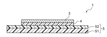
도 1은 본 발명의 실시 형태에 따른 전자 디바이스 패키지용 테이프의 구조를 모식적으로 도시하는 단면도이다.
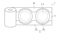
도 2의 (a)는 본 발명의 실시 형태에 따른 전자 디바이스 패키지용 테이프의 구조를 모식적으로 도시하는 평면도이며, (b)는 동 단면도이다.
도 3은 본 발명의 실시 형태에 따른 전자 디바이스 패키지용 테이프의 구조를 모식적으로 도시하는 사시도이다.
도 4는 본 발명의 실시 형태에 따른 전자 디바이스 패키지용 테이프의 제조 방법을 모식적으로 도시하는 설명도이며, (A)는 금속층의 접합 공정을 도시하는 긴 변 방향 단면도이며, (B)는 접착제층의 접합 공정을 도시하는 긴 변 방향 단면도이며, (C)는 프리컷 공정을 도시하는 짧은 변 방향 단면도이며, (D)는 불필요 부분의 제거 공정을 도시하는 사시도이다.
도 5는 본 발명의 실시 형태에 따른 전자 디바이스 패키지용 테이프의 제조 방법을 모식적으로 도시하는 설명도이며, (A)는 점착 테이프의 접합 공정을 도시하는 짧은 변 방향 단면도이며, (B)는 프리컷 공정을 도시하는 짧은 변 방향 단면도이며, (C)는 불필요 부분의 제거 공정을 도시하는 짧은 변 방향 단면도이다.
도 6은 본 발명의 실시 형태에 따른 전자 디바이스 패키지용 테이프의 사용 방법을 모식적으로 설명하는 단면도이다.
도 7은 본 발명의 실시 형태에 따른 전자 디바이스 패키지용 테이프의 사용 방법을 모식적으로 설명하는 단면도이다.
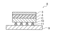
도 8은 본 발명의 실시 형태에 따른 전자 디바이스 패키지용 테이프를 사용한 전자 디바이스 패키지의 구조를 모식적으로 도시하는 단면도이다.FIG. 1 is a cross-sectional view schematically illustrating the structure of a tape for an electronic device package according to an embodiment of the present invention.
Fig. 2 (a) is a plan view schematically illustrating the structure of a tape for an electronic device package according to an embodiment of the present invention, and (b) is a cross-sectional view thereof.
FIG. 3 is a perspective view schematically illustrating the structure of a tape for an electronic device package according to an embodiment of the present invention.
FIG. 4 is a schematic diagram illustrating a method for manufacturing a tape for an electronic device package according to an embodiment of the present invention, wherein (A) is a longitudinal cross-sectional view illustrating a process for bonding a metal layer, (B) is a longitudinal cross-sectional view illustrating a process for bonding an adhesive layer, (C) is a short-side cross-sectional view illustrating a precut process, and (D) is a perspective view illustrating a process for removing an unnecessary portion.
FIG. 5 is an explanatory diagram schematically illustrating a method for manufacturing a tape for an electronic device package according to an embodiment of the present invention, wherein (A) is a short-side cross-sectional view illustrating a bonding process of an adhesive tape, (B) is a short-side cross-sectional view illustrating a precut process, and (C) is a short-side cross-sectional view illustrating a removal process of an unnecessary portion.
FIG. 6 is a cross-sectional view schematically illustrating a method of using a tape for an electronic device package according to an embodiment of the present invention.
FIG. 7 is a cross-sectional view schematically illustrating a method of using a tape for an electronic device package according to an embodiment of the present invention.
FIG. 8 is a cross-sectional view schematically illustrating the structure of an electronic device package using a tape for an electronic device package according to an embodiment of the present invention.
이하에, 본 발명의 실시 형태에 대하여 상세하게 설명한다.Below, embodiments of the present invention are described in detail.
도 1은, 본 발명의 실시 형태에 따른 전자 디바이스 패키지용 테이프(1)를 도시하는 단면도이다. 이 전자 디바이스 패키지용 테이프(1)는 기재 필름(51)과 기재 필름(51) 상에 설치된 점착제층(52)을 포함하는 점착 테이프(5)를 갖고 있으며, 점착제층(52) 상에는, 접착제층(4)과 금속층(3)의 적층체가 설치되어 있다. 본 실시 형태에 있어서는, 점착제층(52) 상에는, 접착제층(4)과, 접착제층(4)에 적층하여 설치된 금속층(3)이 설치되어 있다. 접착제층(4)과 금속층(3)의 적층체는, 양자의 밀착성을 좋게 하기 위한 프라이머층 등을 개재하여 간접적으로 적층되어 있는 양태를 포함한다.Fig. 1 is a cross-sectional view showing a tape (1) for an electronic device package according to an embodiment of the present invention. The tape (1) for an electronic device package has an adhesive tape (5) including a base film (51) and an adhesive layer (52) provided on the base film (51), and a laminate of an adhesive layer (4) and a metal layer (3) is provided on the adhesive layer (52). In the present embodiment, an adhesive layer (4) and a metal layer (3) provided by laminating on the adhesive layer (4) are provided on the adhesive layer (52). The laminate of the adhesive layer (4) and the metal layer (3) includes an aspect in which they are indirectly laminated via a primer layer or the like to improve adhesion between the two.
본 발명의 전자 디바이스 패키지용 테이프(1)는 도 2 및 도 3에 도시한 바와 같이, 점착 테이프(5)가 링 프레임(R)(도 7 참조)에 대응하는 형상으로 절단되어 있고, 금속층(3) 및 접착제층(4)도 이것에 대응하여 소정 형상으로 절단(프리컷 가공)되어 있는 것이 바람직하고, 본 실시 형태에 있어서는 프리컷 가공이 이루어져 있다.As shown in FIGS. 2 and 3, the tape (1) for an electronic device package of the present invention preferably has an adhesive tape (5) cut into a shape corresponding to a ring frame (R) (see FIG. 7), and a metal layer (3) and an adhesive layer (4) also cut into a predetermined shape corresponding thereto (precut processing). In the present embodiment, precut processing is performed.
본 발명의 전자 디바이스 패키지용 테이프(1)는 도 2 및 도 3에 도시한 바와 같이, 금속층(3), 접착제층(4), 링 프레임(R)에 대응하는 형상으로 절단된 점착 테이프(5)(라벨부(5a))가 적층된 적층체가 복수 형성된 긴 기재 테이프(2)를 롤형으로 권취한 형태인 것이 바람직하고, 본 실시 형태에 있어서는 롤형으로 권취되어 있지만, 기재 테이프(2)에 설치된 적층체가 하나씩 절단된 형태여도 된다.As shown in FIGS. 2 and 3, the tape (1) for electronic device packaging of the present invention is preferably in the form of a long base tape (2) wound in a roll shape in which a plurality of laminates are formed, each of which is a metal layer (3), an adhesive layer (4), and an adhesive tape (5) (label portion (5a)) cut into a shape corresponding to a ring frame (R), and the like. In the present embodiment, the tape is wound in a roll shape, but the laminates provided on the base tape (2) may be cut one by one.
프리컷 가공되어 롤형으로 권취되어 있는 경우, 도 2 및 도 3에 도시한 바와 같이, 전자 디바이스 패키지용 테이프(1)는 기재 테이프(2)를 갖고 있으며, 기재 테이프(2) 상에는, 소정의 평면 형상을 갖는 금속층(3)과, 금속층(3)의 기재 테이프(2)측과는 반대측에 금속층(3)과 적층하여 설치되고, 소정의 평면 형상을 갖는 접착제층(4)과, 접착제층(4)을 덮고, 또한, 접착제층(4)의 주위에서 기재 테이프(2)에 접촉하도록 설치된 소정의 평면 형상의 라벨부(5a)와 그 라벨부(5a)의 외측을 둘러싸는 주변부(5b)를 갖는 점착 테이프(5)가 설치되어 있다.When pre-cut and wound into a roll shape, as shown in FIGS. 2 and 3, the tape (1) for an electronic device package has a substrate tape (2), and on the substrate tape (2), a metal layer (3) having a predetermined flat shape, an adhesive layer (4) that is installed by laminating the metal layer (3) on the side opposite to the substrate tape (2) side of the metal layer (3) and has a predetermined flat shape, and an adhesive tape (5) that covers the adhesive layer (4) and has a label portion (5a) of a predetermined flat shape that is installed so as to contact the substrate tape (2) around the adhesive layer (4), and a peripheral portion (5b) that surrounds the outer side of the label portion (5a).
라벨부(5a)는 다이싱용의 링 프레임(R)에 대응하는 형상을 갖는다. 다이싱용의 링 프레임(R)의 형상에 대응하는 형상은, 링 프레임(R)의 내측과 대략 동일한 형상이며 링 프레임(R) 내측의 크기보다 큰 상사형인 것이 바람직하다. 또한, 반드시 원형은 아니어도 되지만, 원형에 가까운 형상이 바람직하고, 원형인 것이 더욱 바람직하다. 주변부(5b)는 라벨부(5a)의 외측을 완전히 둘러싸는 형태와, 도시한 바와 같이 완전히는 둘러싸지 않는 형태를 포함한다. 또한, 주변부(5b)는 설치되어 있지 않아도 된다.The label portion (5a) has a shape corresponding to the ring frame (R) for dicing. The shape corresponding to the shape of the ring frame (R) for dicing is preferably a similar shape that is approximately the same as the inner side of the ring frame (R) and larger than the size of the inner side of the ring frame (R). In addition, it does not necessarily have to be circular, but a shape close to circular is preferable, and a circular shape is more preferable. The peripheral portion (5b) includes a shape that completely surrounds the outer side of the label portion (5a) and a shape that does not completely surround it as illustrated. In addition, the peripheral portion (5b) does not have to be installed.
접착제층(4)은 소정의 평면 형상을 갖고 있으며, 이 평면 형상은, 점착 테이프(5)의 라벨부(5a)의 주연부에 링 프레임(R)을 접합하고, 픽업 장치의 밀어 올림 부재로 밀어 올림 가능하도록(도 7의 (C) 참조) 라벨부(5a)보다도 작은 형상으로 되어 있다. 접착제층(4)은 라벨부(5a)와 대략 동일한 형상이며 라벨부(5a)의 크기보다 작은 상사형인 것이 바람직하다. 접착제층(4)은 반드시 원형은 아니어도 되지만, 원형에 가까운 형상이 바람직하고, 원형인 것이 더욱 바람직하다.The adhesive layer (4) has a predetermined flat shape, and this flat shape is made smaller than the label portion (5a) so that a ring frame (R) can be attached to the periphery of the label portion (5a) of the adhesive tape (5) and pushed up by a pushing member of a pickup device (see (C) of Fig. 7). The adhesive layer (4) is preferably a similar shape that is approximately the same as the label portion (5a) and smaller than the size of the label portion (5a). The adhesive layer (4) does not necessarily have to be circular, but a shape close to circular is preferable, and a circular shape is more preferable.
금속층(3)은 접착제층(4)과는 동일한 형상으로 되어 있고, 금속층(3)에 접착제층(4)이 적층되어 있다. 여기에서 말하는 적층은, 주요 부분이 적층되어 있으면 되고, 금속층(3)과 접착제층(4)이 반드시 동일한 크기일 필요는 없지만, 제조의 편리성으로부터, 대략 동일한 형상인 것이 바람직하다. 이하에, 각 구성 요소에 대하여 설명한다.The metal layer (3) has the same shape as the adhesive layer (4), and the adhesive layer (4) is laminated on the metal layer (3). The lamination referred to here is sufficient as long as the main part is laminated, and the metal layer (3) and the adhesive layer (4) do not necessarily have to have the same size, but from the perspective of manufacturing convenience, it is preferable that they have approximately the same shape. Hereinafter, each component will be described.
<기재 테이프(2)><Recording Tape (2)>
기재 테이프(2)는 공지된 세퍼레이터로 구성할 수도 있지만, 전자 디바이스 패키지용 테이프의 프리컷 가공에 사용하는 기재 테이프를 그대로 사용할 수도 있다. 전자 디바이스 패키지용 테이프의 프리컷 가공에 사용하는 기재 테이프를 그대로 사용하는 경우, 기재 테이프(2)는 프리컷 가공 시에 금속층(3)을 점착 보유 지지할 필요가 있기 때문에, 예를 들어, 수지 필름과 수지 필름의 편면에 설치된 기재 테이프용 점착제층을 갖는 테이프를 적합하게 사용할 수 있다.The substrate tape (2) may be composed of a known separator, but a substrate tape used in the precut processing of a tape for an electronic device package may also be used as is. When a substrate tape used in the precut processing of a tape for an electronic device package is used as is, since the substrate tape (2) needs to adhere and support the metal layer (3) during the precut processing, for example, a tape having a resin film and an adhesive layer for a substrate tape provided on one side of the resin film can be suitably used.
기재 테이프(2)를 구성하는 수지 필름의 소재에는, 공지된 재료를 사용할 수 있는데, 예시한다면, 폴리에스테르(PET, PBT, PEN, PBN, PTT)계, 폴리올레핀(PP, PE)계, 공중합체(EVA, EEA, EBA)계, 또한 이들 재료를 일부 치환하고, 또한 접착성이나 기계적 강도를 향상시킨 필름을 들 수 있다. 또한, 이들 필름의 적층체여도 된다. 내열성, 평활성, 및 입수하기 쉬움의 관점에서, 폴리에틸렌테레프탈레이트, 폴리프로필렌, 및 폴리에틸렌 중에서 선택되는 것이 바람직하다.As the material of the resin film constituting the substrate tape (2), known materials can be used, and examples thereof include polyester (PET, PBT, PEN, PBN, PTT)-based, polyolefin (PP, PE)-based, copolymer (EVA, EEA, EBA)-based, and films in which some of these materials are substituted and further improved in adhesiveness or mechanical strength. Furthermore, a laminate of these films may be used. From the viewpoints of heat resistance, smoothness, and ease of acquisition, it is preferable to select from polyethylene terephthalate, polypropylene, and polyethylene.
기재 테이프(2)를 구성하는 수지 필름의 두께는, 특별히 한정되는 것은 아니며, 적절하게 설정해도 되지만, 10 내지 150㎛인 것이 바람직하다.The thickness of the resin film constituting the substrate tape (2) is not particularly limited and may be set appropriately, but is preferably 10 to 150 ㎛.
기재 테이프용 점착제층에 사용되는 수지로서는, 점착제에 사용되는 공지된 염소화폴리프로필렌 수지, 아크릴 수지, 폴리에스테르 수지, 폴리우레탄 수지, 에폭시 수지 등을 사용할 수 있는데, 아크릴계 폴리머를 베이스 폴리머로 하는 아크릴계 점착제가 바람직하다.As the resin used in the adhesive layer for the substrate tape, known chlorinated polypropylene resins, acrylic resins, polyester resins, polyurethane resins, epoxy resins, etc. used in adhesives can be used, but an acrylic adhesive using an acrylic polymer as a base polymer is preferable.
아크릴계 폴리머로서는, 예를 들어, (메트)아크릴산알킬에스테르(예를 들어, 메틸에스테르, 에틸에스테르, 프로필에스테르, 이소프로필에스테르, 부틸에스테르, 이소부틸에스테르, s-부틸에스테르, t-부틸에스테르, 펜틸에스테르, 이소펜틸에스테르, 헥실에스테르, 헵틸에스테르, 옥틸에스테르, 2-에틸헥실에스테르, 이소옥틸에스테르, 노닐에스테르, 데실에스테르, 이소데실에스테르, 운데실에스테르, 도데실에스테르, 트리데실에스테르, 테트라데실에스테르, 헥사데실에스테르, 옥타데실에스테르, 에이코실에스테르 등의 알킬기의 탄소수 1 내지 30, 특히 탄소수 4 내지 18의 직쇄상 또는 분지쇄상의 알킬에스테르 등) 및 (메트)아크릴산시클로알킬에스테르(예를 들어, 시클로펜틸에스테르, 시클로헥실에스테르 등)의 1종 또는 2종 이상을 단량체 성분으로서 사용한 아크릴계 폴리머 등을 들 수 있다. 또한, (메트)아크릴산에스테르란 아크릴산에스테르 및/또는 메타크릴산에스테르를 말하며, 본 발명의 (메트)란 모두 동일한 의미이다.As acrylic polymers, for example, (meth)acrylic acid alkyl esters (for example, methyl ester, ethyl ester, propyl ester, isopropyl ester, butyl ester, isobutyl ester, s-butyl ester, t-butyl ester, pentyl ester, isopentyl ester, hexyl ester, heptyl ester, octyl ester, 2-ethylhexyl ester, isooctyl ester, nonyl ester, decyl ester, isodecyl ester, undecyl ester, dodecyl ester, tridecyl ester, tetradecyl ester, hexadecyl ester, octadecyl ester, eicosyl ester, etc., linear or branched alkyl esters having 1 to 30 carbon atoms in the alkyl group, particularly 4 to 18 carbon atoms) and Examples thereof include acrylic polymers using one or more types of (meth)acrylic acid cycloalkyl esters (e.g., cyclopentyl ester, cyclohexyl ester, etc.) as monomer components. In addition, (meth)acrylic acid ester refers to acrylic acid ester and/or methacrylic acid ester, and (meth) in the present invention has the same meaning.
아크릴계 폴리머는, 응집력, 내열성 등의 개질을 목적으로 하고, 필요에 따라, 상기 (메트)아크릴산알킬에스테르 또는 시클로알킬에스테르와 공중합 가능한 다른 모노머 성분에 대응하는 단위를 포함하고 있어도 된다. 이와 같은 모노머 성분으로서, 예를 들어, 아크릴산, 메타크릴산, 카르복시에틸(메트)아크릴레이트, 카르복시펜틸(메트)아크릴레이트, 이타콘산, 말레산, 푸마르산, 크로톤산 등의 카르복실기 함유 모노머; 무수 말레산, 무수 이타콘산 등의 산 무수물 모노머; (메트)아크릴산2-히드록시에틸, (메트)아크릴산2-히드록시프로필, (메트)아크릴산4-히드록시부틸, (메트)아크릴산6-히드록시헥실, (메트)아크릴산8-히드록시옥틸, (메트)아크릴산10-히드록시데실, (메트)아크릴산12-히드록시라우릴, (4-히드록시메틸시클로헥실)메틸(메트)아크릴레이트 등의 히드록실기 함유 모노머; 스티렌술폰산, 알릴술폰산, 2-(메트)아크릴아미드-2-메틸프로판술폰산, (메트)아크릴아미도프로판술폰산, 술포프로필(메트)아크릴레이트, (메트)아크릴로일옥시나프탈렌술폰산 등의 술폰산기 함유 모노머; 2-히드록시에틸아크릴로일포스페이트 등의 인산기 함유 모노머; 아크릴아미드, 아크릴로니트릴 등을 들 수 있다. 이들 공중합 가능한 모노머 성분은, 1종 또는 2종 이상 사용할 수 있다. 이들 공중합 가능한 모노머의 사용량은, 전체 단량체 성분의 40중량% 이하가 바람직하다.Acrylic polymers may contain units corresponding to other monomer components copolymerizable with the (meth)acrylic acid alkyl ester or cycloalkyl ester, if necessary, for the purpose of modifying cohesion, heat resistance, etc. As such monomer components, for example, carboxyl group-containing monomers such as acrylic acid, methacrylic acid, carboxyethyl (meth)acrylate, carboxypentyl (meth)acrylate, itaconic acid, maleic acid, fumaric acid, and crotonic acid; acid anhydride monomers such as maleic anhydride and itaconic anhydride; Hydroxyl group-containing monomers such as (meth)acrylate 2-hydroxyethyl, (meth)acrylate 2-hydroxypropyl, (meth)acrylate 4-hydroxybutyl, (meth)acrylate 6-hydroxyhexyl, (meth)acrylate 8-hydroxyoctyl, (meth)acrylate 10-hydroxydecyl, (meth)acrylate 12-hydroxylauryl, (4-hydroxymethylcyclohexyl)methyl (meth)acrylate, etc.; Sulfonic acid group-containing monomers such as styrenesulfonic acid, allylsulfonic acid, 2-(meth)acrylamide-2-methylpropanesulfonic acid, (meth)acrylamidopropanesulfonic acid, sulfopropyl (meth)acrylate, (meth)acryloyloxynaphthalenesulfonic acid, etc. Monomers containing a phosphoric acid group such as 2-hydroxyethylacryloylphosphate; acrylamide, acrylonitrile, etc. These copolymerizable monomer components can be used alone or in combination of two or more. The amount of these copolymerizable monomers used is preferably 40 wt% or less of the total monomer components.
또한, 아크릴계 폴리머는, 가교되기 때문에, 다관능성 모노머 등도 필요에 따라서 공중합용 모노머 성분으로서 포함할 수 있다. 이와 같은 다관능성 모노머로서, 예를 들어, 헥산디올디(메트)아크릴레이트, (폴리)에틸렌글리콜디(메트)아크릴레이트, (폴리)프로필렌글리콜디(메트)아크릴레이트, 네오펜틸글리콜디(메트)아크릴레이트, 펜타에리트리톨디(메트)아크릴레이트, 트리메틸올프로판트리(메트)아크릴레이트, 펜타에리트리톨트리(메트)아크릴레이트, 디펜타에리트리톨헥사(메트)아크릴레이트, 에폭시(메트)아크릴레이트, 폴리에스테르(메트)아크릴레이트, 우레탄(메트)아크릴레이트 등을 들 수 있다. 이들 다관능성 모노머도 1종 또는 2종 이상 사용할 수 있다. 다관능성 모노머의 사용량은, 점착 특성 등의 점에서, 전체 단량체 성분의 30중량% 이하가 바람직하다.In addition, since the acrylic polymer is crosslinked, it can also include a polyfunctional monomer as a copolymerization monomer component as needed. As such polyfunctional monomers, for example, hexanediol di(meth)acrylate, (poly)ethylene glycol di(meth)acrylate, (poly)propylene glycol di(meth)acrylate, neopentyl glycol di(meth)acrylate, pentaerythritol di(meth)acrylate, trimethylolpropane tri(meth)acrylate, pentaerythritol tri(meth)acrylate, dipentaerythritol hexa(meth)acrylate, epoxy(meth)acrylate, polyester(meth)acrylate, urethane(meth)acrylate, etc. These polyfunctional monomers can also be used alone or in combination of two or more. The amount of polyfunctional monomer used is preferably 30 wt% or less of the total monomer components from the viewpoint of adhesive properties, etc.
아크릴계 폴리머의 조제는 예를 들어 1종 또는 2종 이상의 성분 모노머의 혼합물에 용액 중합 방식이나 유화 중합 방식, 괴상 중합 방식이나 현탁 중합 방식 등의 적절한 방식을 적용하여 행할 수 있다. 기재 테이프용 점착제층은, 저분자량 물질의 함유를 억제한 조성이 바람직하고, 이러한 점에서 중량 평균 분자량이 30만 이상, 특히 40만 내지 300만인 아크릴계 폴리머를 주성분으로 하는 것이 바람직한 것으로부터 점착제는, 내부 가교 방식이나 외부 가교 방식 등에 의한 적절한 가교 타입으로 할 수도 있다.The preparation of the acrylic polymer can be carried out by applying an appropriate method, such as a solution polymerization method, an emulsion polymerization method, a bulk polymerization method, or a suspension polymerization method, to a mixture of one or more types of monomer components, for example. The pressure-sensitive adhesive layer for the base tape is preferably composed of a composition that suppresses the content of low molecular weight substances, and from this point of view, it is preferable to use as a main component an acrylic polymer having a weight average molecular weight of 300,000 or more, particularly 400,000 to 3,000,000, so the adhesive can also be of an appropriate crosslinking type, such as an internal crosslinking method or an external crosslinking method.
또한, 기재 테이프용 점착제층의 가교 밀도를 제어하여 점착 테이프(5)와의 박리성을 향상시키기 위해서, 예를 들어 다관능 이소시아네이트계 화합물, 다관능 에폭시계 화합물, 멜라민계 화합물, 금속염계 화합물, 금속 킬레이트계 화합물, 아미노 수지계 화합물, 또는 과산화물 등의 적절한 외부 가교제를 사용하여 가교 처리하는 방식이나, 탄소-탄소 이중 결합을 2개 이상 갖는 저분자 화합물을 혼합하여 에너지선의 조사 등에 의해 가교 처리하는 방식 등의 적절한 방식을 채용할 수 있다. 외부 가교제를 사용하는 경우, 그 사용량은, 가교해야 할 베이스 폴리머와의 밸런스에 따라, 나아가, 점착제로서의 사용 용도에 따라 적절히 결정된다. 일반적으로는, 상기 베이스 폴리머 100중량부에 대하여 20중량부 정도 이하, 나아가 0.1중량부 내지 20중량부 배합하는 것이 바람직하다.In addition, in order to control the crosslinking density of the adhesive layer for the base tape and improve the peelability from the adhesive tape (5), an appropriate method such as a method of crosslinking using an appropriate external crosslinking agent such as a polyfunctional isocyanate compound, a polyfunctional epoxy compound, a melamine compound, a metal salt compound, a metal chelate compound, an amino resin compound, or a peroxide, or a method of mixing a low molecular weight compound having two or more carbon-carbon double bonds and crosslinking by irradiation with energy rays, etc. can be adopted. When an external crosslinking agent is used, the amount thereof used is appropriately determined depending on the balance with the base polymer to be crosslinked and further depending on the intended use as the adhesive. Generally, it is preferable to blend in an amount of about 20 parts by weight or less, further 0.1 to 20 parts by weight, with respect to 100 parts by weight of the base polymer.
기재 테이프용 점착제층의 두께는, 특별히 제한되지 않고 적절하게 결정할 수 있지만, 일반적으로는 5 내지 200㎛ 정도이다. 또한, 기재 테이프용 점착제층은 단층으로 구성되어도 되고, 복수층으로 구성되어 있어도 된다.The thickness of the adhesive layer for the substrate tape is not particularly limited and can be appropriately determined, but is generally about 5 to 200 ㎛. In addition, the adhesive layer for the substrate tape may be composed of a single layer or multiple layers.
<점착 테이프(5)><Adhesive Tape (5)>
점착 테이프(5)로서는, 특별히 제한은 없고, 종래의 점착 테이프를 사용할 수 있다. 점착 테이프(5)로서, 예를 들어, 기재 필름(51)에 점착제층(52)을 설치한 것을 적합하게 사용할 수 있다.As the adhesive tape (5), there is no particular limitation, and a conventional adhesive tape can be used. As the adhesive tape (5), for example, one in which an adhesive layer (52) is installed on a base film (51) can be suitably used.
기재 필름(51)으로서는, 종래 공지의 것이기만 하면 특별히 제한하지 않고 사용할 수 있지만, 후술하는 점착제층(52)으로서 방사선 경화성의 재료를 사용하는 경우에는, 방사선 투과성을 갖는 것을 사용하는 것이 바람직하다.As the base film (51), any known material can be used without particular limitation. However, when using a radiation-curable material as the adhesive layer (52) described later, it is preferable to use one that is radiation-transparent.
예를 들어, 그 재료로서, 폴리에틸렌, 폴리프로필렌, 에틸렌-프로필렌 공중합체, 폴리부텐-1, 폴리-4-메틸펜텐-1, 에틸렌-아세트산비닐 공중합체, 에틸렌-아크릴산에틸 공중합체, 에틸렌-아크릴산메틸 공중합체, 에틸렌-아크릴산 공중합체, 아이오노머 등의 α-올레핀의 단독중합체 또는 공중합체 또는 이들의 혼합물, 폴리우레탄, 스티렌-에틸렌-부텐 또는 펜텐계 공중합체, 폴리아미드-폴리올 공중합체 등의 열가소성 엘라스토머, 및 이들의 혼합물을 열거할 수 있다. 또한, 기재 필름은 이들의 군에서 선택되는 2종 이상의 재료가 혼합된 것이어도 되고, 이들이 단층 또는 복층화된 것이어도 된다.For example, as the material, homopolymers or copolymers of α-olefins such as polyethylene, polypropylene, ethylene-propylene copolymer, polybutene-1, poly-4-methylpentene-1, ethylene-vinyl acetate copolymer, ethylene-ethyl acrylate copolymer, ethylene-methyl acrylate copolymer, ethylene-acrylic acid copolymer, ionomers, thermoplastic elastomers such as polyurethane, styrene-ethylene-butene or pentene copolymers, polyamide-polyol copolymers, and mixtures thereof can be enumerated. In addition, the base film may be a mixture of two or more materials selected from these groups, or may be a single-layer or multi-layered one.
기재 필름(51)의 두께는, 특별히 한정되는 것은 아니며, 적절하게 설정해도 되지만, 50 내지 200㎛인 것이 바람직하다.The thickness of the substrate film (51) is not particularly limited and may be set appropriately, but is preferably 50 to 200 ㎛.
기재 필름(51)과 점착제층(52)의 밀착성을 향상시키기 위해서, 기재 필름(51)의 표면에, 크롬산 처리, 오존 폭로, 화염 폭로, 고압 전격 폭로, 이온화 방사선 처리 등의 화학적 또는 물리적 표면 처리를 실시해도 된다.In order to improve the adhesion between the substrate film (51) and the adhesive layer (52), chemical or physical surface treatment such as chromic acid treatment, ozone exposure, flame exposure, high-voltage electric shock exposure, or ionizing radiation treatment may be performed on the surface of the substrate film (51).
또한, 본 실시 형태에 있어서는, 기재 필름(51) 상에 직접적으로 점착제층(52)을 설치했지만, 밀착성을 높이기 위한 프라이머층이나, 다이싱 시의 절삭성 향상을 위한 앵커층, 응력 완화층, 정전 방지층 등을 통하여 간접적으로 설치해도 된다.In addition, in this embodiment, the adhesive layer (52) is directly installed on the substrate film (51), but it may be installed indirectly through a primer layer for increasing adhesion, an anchor layer for improving cutting properties during dicing, a stress relief layer, an antistatic layer, or the like.
점착 테이프(5)의 점착제층(52)에 사용되는 수지로서는, 특별히 한정되는 것은 아니며, 점착제에 사용되는 공지된 염소화폴리프로필렌 수지, 아크릴 수지, 폴리에스테르 수지, 폴리우레탄 수지, 에폭시 수지 등을 사용할 수 있는데, 아크릴계 폴리머를 베이스 폴리머로 하는 아크릴계 점착제가 바람직하다.The resin used in the adhesive layer (52) of the adhesive tape (5) is not particularly limited, and known chlorinated polypropylene resins, acrylic resins, polyester resins, polyurethane resins, epoxy resins, etc. used in adhesives can be used, but an acrylic adhesive using an acrylic polymer as a base polymer is preferable.
아크릴계 폴리머로서는, 예를 들어, (메트)아크릴산알킬에스테르(예를 들어, 메틸에스테르, 에틸에스테르, 프로필에스테르, 이소프로필에스테르, 부틸에스테르, 이소부틸에스테르, s-부틸에스테르, t-부틸에스테르, 펜틸에스테르, 이소펜틸에스테르, 헥실에스테르, 헵틸에스테르, 옥틸에스테르, 2-에틸헥실에스테르, 이소옥틸에스테르, 노닐에스테르, 데실에스테르, 이소데실에스테르, 운데실에스테르, 도데실에스테르, 트리데실에스테르, 테트라데실에스테르, 헥사데실에스테르, 옥타데실에스테르, 에이코실에스테르 등의 알킬기의 탄소수 1 내지 30, 특히 탄소수 4 내지 18의 직쇄상 또는 분지쇄상의 알킬에스테르 등) 및 (메트)아크릴산시클로알킬에스테르(예를 들어, 시클로펜틸에스테르, 시클로헥실에스테르 등)의 1종 또는 2종 이상을 단량체 성분으로서 사용한 아크릴계 폴리머 등을 들 수 있다. 또한, (메트)아크릴산에스테르란 아크릴산에스테르 및/또는 메타크릴산에스테르를 말하며, 본 발명의 (메트)란 모두 동일한 의미이다.As acrylic polymers, for example, (meth)acrylic acid alkyl esters (for example, methyl ester, ethyl ester, propyl ester, isopropyl ester, butyl ester, isobutyl ester, s-butyl ester, t-butyl ester, pentyl ester, isopentyl ester, hexyl ester, heptyl ester, octyl ester, 2-ethylhexyl ester, isooctyl ester, nonyl ester, decyl ester, isodecyl ester, undecyl ester, dodecyl ester, tridecyl ester, tetradecyl ester, hexadecyl ester, octadecyl ester, eicosyl ester, etc., linear or branched alkyl esters having 1 to 30 carbon atoms in the alkyl group, particularly 4 to 18 carbon atoms) and Examples thereof include acrylic polymers using one or more types of (meth)acrylic acid cycloalkyl esters (e.g., cyclopentyl ester, cyclohexyl ester, etc.) as monomer components. In addition, (meth)acrylic acid ester refers to acrylic acid ester and/or methacrylic acid ester, and (meth) in the present invention has the same meaning.
아크릴계 폴리머는, 응집력, 내열성 등의 개질을 목적으로 하고, 필요에 따라, 상기 (메트)아크릴산알킬에스테르 또는 시클로알킬에스테르와 공중합 가능한 다른 모노머 성분에 대응하는 단위를 포함하고 있어도 된다. 이와 같은 모노머 성분으로서, 예를 들어, 아크릴산, 메타크릴산, 카르복시에틸(메트)아크릴레이트, 카르복시펜틸(메트)아크릴레이트, 이타콘산, 말레산, 푸마르산, 크로톤산 등의 카르복실기 함유 모노머; 무수 말레산, 무수 이타콘산 등의 산 무수물 모노머; (메트)아크릴산2-히드록시에틸, (메트)아크릴산2-히드록시프로필, (메트)아크릴산4-히드록시부틸, (메트)아크릴산6-히드록시헥실, (메트)아크릴산8-히드록시옥틸, (메트)아크릴산10-히드록시데실, (메트)아크릴산12-히드록시라우릴, (4-히드록시메틸시클로헥실)메틸(메트)아크릴레이트 등의 히드록실기 함유 모노머; 스티렌술폰산, 알릴술폰산, 2-(메트)아크릴아미드-2-메틸프로판술폰산, (메트)아크릴아미도프로판술폰산, 술포프로필(메트)아크릴레이트, (메트)아크릴로일옥시나프탈렌술폰산 등의 술폰산기 함유 모노머; 2-히드록시에틸아크릴로일포스페이트 등의 인산기 함유 모노머; 아크릴아미드, 아크릴로니트릴 등을 들 수 있다. 이들 공중합 가능한 모노머 성분은, 1종 또는 2종 이상 사용할 수 있다. 이들 공중합 가능한 모노머의 사용량은, 전체 단량체 성분의 40중량% 이하가 바람직하다.Acrylic polymers may contain units corresponding to other monomer components copolymerizable with the (meth)acrylic acid alkyl ester or cycloalkyl ester, if necessary, for the purpose of modifying cohesion, heat resistance, etc. As such monomer components, for example, carboxyl group-containing monomers such as acrylic acid, methacrylic acid, carboxyethyl (meth)acrylate, carboxypentyl (meth)acrylate, itaconic acid, maleic acid, fumaric acid, and crotonic acid; acid anhydride monomers such as maleic anhydride and itaconic anhydride; Hydroxyl group-containing monomers such as (meth)acrylate 2-hydroxyethyl, (meth)acrylate 2-hydroxypropyl, (meth)acrylate 4-hydroxybutyl, (meth)acrylate 6-hydroxyhexyl, (meth)acrylate 8-hydroxyoctyl, (meth)acrylate 10-hydroxydecyl, (meth)acrylate 12-hydroxylauryl, (4-hydroxymethylcyclohexyl)methyl (meth)acrylate, etc.; Sulfonic acid group-containing monomers such as styrenesulfonic acid, allylsulfonic acid, 2-(meth)acrylamide-2-methylpropanesulfonic acid, (meth)acrylamidopropanesulfonic acid, sulfopropyl (meth)acrylate, (meth)acryloyloxynaphthalenesulfonic acid, etc. Monomers containing a phosphoric acid group such as 2-hydroxyethylacryloylphosphate; acrylamide, acrylonitrile, etc. These copolymerizable monomer components can be used alone or in combination of two or more. The amount of these copolymerizable monomers used is preferably 40 wt% or less of the total monomer components.
또한, 아크릴계 폴리머는, 가교되기 때문에, 다관능성 모노머 등도 필요에 따라서 공중합용 모노머 성분으로서 포함할 수 있다. 이와 같은 다관능성 모노머로서, 예를 들어, 헥산디올디(메트)아크릴레이트, (폴리)에틸렌글리콜디(메트)아크릴레이트, (폴리)프로필렌글리콜디(메트)아크릴레이트, 네오펜틸글리콜디(메트)아크릴레이트, 펜타에리트리톨디(메트)아크릴레이트, 트리메틸올프로판트리(메트)아크릴레이트, 펜타에리트리톨트리(메트)아크릴레이트, 디펜타에리트리톨헥사(메트)아크릴레이트, 에폭시(메트)아크릴레이트, 폴리에스테르(메트)아크릴레이트, 우레탄(메트)아크릴레이트 등을 들 수 있다. 이들 다관능성 모노머도 1종 또는 2종 이상 사용할 수 있다. 다관능성 모노머의 사용량은, 점착 특성 등의 점에서, 전체 단량체 성분의 30중량% 이하가 바람직하다.In addition, since the acrylic polymer is crosslinked, it can also include a polyfunctional monomer as a copolymerization monomer component as needed. As such polyfunctional monomers, for example, hexanediol di(meth)acrylate, (poly)ethylene glycol di(meth)acrylate, (poly)propylene glycol di(meth)acrylate, neopentyl glycol di(meth)acrylate, pentaerythritol di(meth)acrylate, trimethylolpropane tri(meth)acrylate, pentaerythritol tri(meth)acrylate, dipentaerythritol hexa(meth)acrylate, epoxy(meth)acrylate, polyester(meth)acrylate, urethane(meth)acrylate, etc. These polyfunctional monomers can also be used alone or in combination of two or more. The amount of polyfunctional monomer used is preferably 30 wt% or less of the total monomer components from the viewpoint of adhesive properties, etc.
아크릴계 폴리머의 조제는 예를 들어 1종 또는 2종 이상의 성분 모노머의 혼합물에 용액 중합 방식이나 유화 중합 방식, 괴상 중합 방식이나 현탁 중합 방식 등의 적절한 방식을 적용하여 행할 수 있다. 점착제층은, 웨이퍼의 오염 방지 등의 점에서 저분자량 물질의 함유를 억제한 조성이 바람직하고, 이러한 점에서 중량 평균 분자량이 30만 이상, 특히 40만 내지 300만인 아크릴계 폴리머를 주성분으로 하는 것이 바람직한 것으로부터 점착제는, 내부 가교 방식이나 외부 가교 방식 등에 의한 적절한 가교 타입으로 할 수도 있다.The preparation of the acrylic polymer can be carried out by applying an appropriate method, such as a solution polymerization method, an emulsion polymerization method, a bulk polymerization method, or a suspension polymerization method, to a mixture of one or more types of monomer components, for example. The adhesive layer is preferably composed of a composition that suppresses the content of low molecular weight substances in terms of preventing contamination of the wafer, and from this point of view, it is preferable to use as a main component an acrylic polymer having a weight average molecular weight of 300,000 or more, particularly 400,000 to 3,000,000, so the adhesive can also be of an appropriate crosslinking type, such as an internal crosslinking method or an external crosslinking method.
또한, 점착제층(52)의 가교 밀도를 제어하여 픽업성을 향상시키기 위해서, 예를 들어 다관능 이소시아네이트계 화합물, 다관능 에폭시계 화합물, 멜라민계 화합물, 금속염계 화합물, 금속 킬레이트계 화합물, 아미노 수지계 화합물, 또는 과산화물 등의 적절한 외부 가교제를 사용하여 가교 처리하는 방식이나, 탄소-탄소 이중 결합을 2개 이상 갖는 저분자 화합물을 혼합하여 에너지선의 조사 등에 의해 가교 처리하는 방식 등의 적절한 방식을 채용할 수 있다. 외부 가교제를 사용하는 경우, 그 사용량은, 가교해야 할 베이스 폴리머와의 밸런스에 따라, 나아가, 점착제로서의 사용 용도에 따라 적절히 결정된다. 일반적으로는, 상기 베이스 폴리머 100중량부에 대하여 20중량부 정도 이하, 나아가 0.1중량부 내지 20중량부 배합하는 것이 바람직하다. 또한, 점착제에는, 열화 방지 등의 관점에서, 필요에 따라, 상기 성분 외에, 각종 점착 부여제, 노화 방지제 등의 첨가제를 사용해도 된다.In addition, in order to control the crosslinking density of the adhesive layer (52) to improve the pick-up property, for example, a method of crosslinking using an appropriate external crosslinking agent such as a polyfunctional isocyanate compound, a polyfunctional epoxy compound, a melamine compound, a metal salt compound, a metal chelate compound, an amino resin compound, or a peroxide, or a method of crosslinking by mixing a low-molecular-weight compound having two or more carbon-carbon double bonds and irradiating the mixture with energy rays, etc., can be adopted. When an external crosslinking agent is used, the amount thereof used is appropriately determined depending on the balance with the base polymer to be crosslinked, and further depending on the intended use as the adhesive. Generally, it is preferable to blend in an amount of about 20 parts by weight or less, more preferably 0.1 to 20 parts by weight, with respect to 100 parts by weight of the base polymer. In addition, in the adhesive, from the viewpoint of preventing deterioration, etc., various additives such as tackifiers and anti-aging agents may be used in addition to the above components, as necessary.
점착제층(52)을 구성하는 점착제로서는, 방사선 경화형 점착제가 바람직하다. 방사선 경화형 점착제로서는, 전술한 점착제에, 방사선 경화성의 모노머 성분이나 방사선 경화성의 올리고머 성분을 배합한 첨가형의 방사선 경화형 점착제를 예시할 수 있다.As the adhesive constituting the adhesive layer (52), a radiation-curable adhesive is preferable. As the radiation-curable adhesive, an example of an additive-type radiation-curable adhesive in which a radiation-curable monomer component or a radiation-curable oligomer component is mixed with the above-mentioned adhesive can be exemplified.
배합하는 방사선 경화성의 모노머 성분으로서는, 예를 들어, 우레탄(메트)아크릴레이트, 트리메틸올프로판트리(메트)아크릴레이트, 테트라메틸올메탄테트라(메트)아크릴레이트, 펜타에리트리톨트리(메트)아크릴레이트, 펜타에리트리톨테트라(메트)아크릴레이트, 디펜타에리트리톨모노히드록시펜타(메트)아크릴레이트, 디펜타에리트리톨헥사(메트)아크릴레이트, 1,4-부탄디올디(메트)아크릴레이트 등을 들 수 있다. 이들 모노머 성분은, 1종 또는 2종 이상 병용할 수 있다.Examples of the radiation-curable monomer component to be mixed include urethane (meth)acrylate, trimethylolpropane tri(meth)acrylate, tetramethylolmethane tetra(meth)acrylate, pentaerythritol tri(meth)acrylate, pentaerythritol tetra(meth)acrylate, dipentaerythritol monohydroxypenta(meth)acrylate, dipentaerythritol hexa(meth)acrylate, 1,4-butanediol di(meth)acrylate, etc. These monomer components can be used alone or in combination of two or more.
또한, 방사선 경화성의 올리고머 성분은 우레탄계, 폴리에테르계, 폴리에스테르계, 폴리카르보네이트계, 폴리부타디엔계 등 여러가지의 올리고머를 들 수 있고, 그 분자량이 100 내지 30000 정도의 범위의 것이 적당하다. 방사선 경화성의 모노머 성분이나 올리고머 성분의 배합량은, 상기 점착제층의 종류에 따라, 점착제층의 점착력을 저하할 수 있는 양을 적절하게 결정할 수 있다. 일반적으로는, 점착제를 구성하는 아크릴계 폴리머 등의 베이스 폴리머 100중량부에 대하여 예를 들어 5중량부 내지 500중량부, 바람직하게는 70중량부 내지 150중량부 정도이다.In addition, the radiation-curable oligomer component can include various oligomers such as urethane-based, polyether-based, polyester-based, polycarbonate-based, and polybutadiene-based, and the molecular weight thereof is suitably in the range of about 100 to 30,000. The blending amount of the radiation-curable monomer component or oligomer component can be appropriately determined in an amount capable of reducing the adhesive strength of the adhesive layer depending on the type of the adhesive layer. Generally, it is, for example, about 5 to 500 parts by weight, and preferably about 70 to 150 parts by weight, relative to 100 parts by weight of the base polymer such as the acrylic polymer constituting the adhesive.
또한, 방사선 경화형 점착제로서는, 상기 첨가형의 방사선 경화형 점착제 이외에, 베이스 폴리머로서 탄소-탄소 이중 결합을 폴리머 측쇄 또는 주쇄 중 또는 주쇄 말단에 갖는 것을 사용한 내재형의 방사선 경화형 점착제도 들 수 있다. 내재형의 방사선 경화형 점착제는, 저분자 성분인 올리고머 성분 등을 함유할 필요가 없거나, 또는 많이 포함하지는 않기 때문에, 경시적으로 올리고머 성분 등이 점착제 중에서 이동하지 않고, 안정된 층 구조의 점착제층을 형성할 수 있기 때문에 바람직하다.In addition, as the radiation-curable adhesive, in addition to the above-mentioned additive-type radiation-curable adhesive, there may also be mentioned an inherent-type radiation-curable adhesive using a base polymer having a carbon-carbon double bond in the polymer side chain or main chain or at the main chain terminal. The inherent-type radiation-curable adhesive is preferable because it does not need to contain, or does not contain, a low-molecular-weight component such as an oligomer component, or does not contain much of it, so that the oligomer component does not move in the adhesive over time, and an adhesive layer having a stable layer structure can be formed.
탄소-탄소 이중 결합을 갖는 베이스 폴리머는, 탄소-탄소 이중 결합을 갖고, 또한 점착성을 갖는 것을 특별히 제한없이 사용할 수 있다. 이와 같은 베이스 폴리머로서는, 아크릴계 폴리머를 기본 골격으로 하는 것이 바람직하다. 아크릴계 폴리머의 기본 골격으로서는, 상기 예시한 아크릴계 폴리머를 들 수 있다.The base polymer having a carbon-carbon double bond can be used without particular limitation as long as it has a carbon-carbon double bond and also has adhesiveness. As such a base polymer, an acrylic polymer is preferable as the basic skeleton. As the basic skeleton of the acrylic polymer, the acrylic polymers exemplified above can be mentioned.
아크릴계 폴리머에의 탄소-탄소 이중 결합의 도입법은 특별히 제한되지 않고, 여러가지 방법을 채용할 수 있지만, 탄소-탄소 이중 결합은 폴리머 측쇄에 도입하는 것이 분자 설계상 용이하다. 예를 들어, 미리, 아크릴계 폴리머에 관능기를 갖는 모노머를 공중합한 후, 이 관능기와 반응할 수 있는 관능기 및 탄소-탄소 이중 결합을 갖는 화합물을, 탄소-탄소 이중 결합의 방사선 경화성을 유지한 채 축합 또는 부가 반응시키는 방법을 들 수 있다.The method for introducing a carbon-carbon double bond into an acrylic polymer is not particularly limited, and various methods can be employed, but it is easy to introduce a carbon-carbon double bond into a polymer side chain in terms of molecular design. For example, a method may be exemplified in which a monomer having a functional group is copolymerized with an acrylic polymer in advance, and then a compound having a functional group capable of reacting with the functional group and a carbon-carbon double bond is condensed or added while maintaining the radiation curability of the carbon-carbon double bond.
이들 관능기의 조합의 예로서는, 카르복실산기와 에폭시기, 카르복실산기와 아지리딜기, 히드록실기와 이소시아네이트기 등을 들 수 있다. 이들 관능기의 조합 중에서도 반응 추적의 용이함 때문에, 히드록실기와 이소시아네이트기의 조합이 바람직하다. 또한, 이들 관능기의 조합에 의해, 상기 탄소-탄소 이중 결합을 갖는 아크릴계 폴리머를 생성하는 조합이기만 하면, 관능기는 아크릴계 폴리머와 상기 화합물의 어느 측에 있어도 되지만, 상기한 바람직한 조합에서는, 아크릴계 폴리머가 히드록실기를 갖고, 상기 화합물이 이소시아네이트기를 갖는 경우가 바람직하다. 이 경우, 탄소-탄소 이중 결합을 갖는 이소시아네이트 화합물로서는, 예를 들어, 메타크릴로일이소시아네이트, 2-메타크릴로일옥시에틸이소시아네이트, m-이소프로페닐-α,α-디메틸벤질이소시아네이트 등을 들 수 있다. 또한, 아크릴계 폴리머로서는, 상기 예시된 히드록시기 함유 모노머나 2-히드록시에틸비닐에테르, 4-히드록시부틸비닐에테르, 디에틸렌글리콜모노비닐에테르 등의 에테르계 화합물 등을 공중합한 것이 사용된다.Examples of combinations of these functional groups include a carboxylic acid group and an epoxy group, a carboxylic acid group and an aziridyl group, a hydroxyl group and an isocyanate group, etc. Among these combinations of functional groups, a combination of a hydroxyl group and an isocyanate group is preferable because of the ease of tracking the reaction. In addition, as long as the combination of these functional groups produces an acrylic polymer having the carbon-carbon double bond, the functional group may be on either side of the acrylic polymer and the compound, but in the preferable combination described above, it is preferable that the acrylic polymer has a hydroxyl group and the compound has an isocyanate group. In this case, examples of the isocyanate compound having a carbon-carbon double bond include methacryloyl isocyanate, 2-methacryloyloxyethyl isocyanate, m-isopropenyl-α,α-dimethylbenzyl isocyanate, and the like. In addition, as acrylic polymers, copolymers of the hydroxyl group-containing monomers exemplified above or ether compounds such as 2-hydroxyethyl vinyl ether, 4-hydroxybutyl vinyl ether, and diethylene glycol monovinyl ether are used.
내재형의 방사선 경화형 점착제는, 상기 탄소-탄소 이중 결합을 갖는 베이스 폴리머(특히 아크릴계 폴리머)를 단독으로 사용할 수 있지만, 특성을 악화시키지 않을 정도로 상기 방사선 경화성의 모노머 성분이나 올리고머 성분 등의 광중합성 화합물을 배합할 수도 있다. 당해 광중합성 화합물의 배합량은, 통상 베이스 폴리머 100중량부에 대하여 30중량부 이하의 범위 내이며, 바람직하게는 0 내지 10중량부의 범위 내이다.The inherent radiation-curable pressure-sensitive adhesive can use the base polymer having the carbon-carbon double bond (particularly an acrylic polymer) alone, but can also blend a photopolymerizable compound such as the radiation-curable monomer component or oligomer component so long as the properties are not deteriorated. The blending amount of the photopolymerizable compound is usually within a range of 30 parts by weight or less, and preferably within a range of 0 to 10 parts by weight, relative to 100 parts by weight of the base polymer.
방사선 경화형 점착제에는, 자외선 등에 의해 경화시킨 경우에는 광중합 개시제를 함유시키는 것이 바람직하다.In the case of radiation-curable adhesives, it is preferable to contain a photopolymerization initiator when curing by ultraviolet rays or the like.
상술한 아크릴계 폴리머 중에서도, 특히 CH2=CHCOOR(식 중, R은 탄소수가 4 내지 18인 알킬기이다.)로 표시되는 아크릴산에스테르와, 히드록실기 함유 모노머와, 분자 내에 라디칼 반응성 탄소-탄소 이중 결합을 갖는 이소시아네이트 화합물을 포함하여 구성되는 아크릴계 폴리머 A가 바람직하다.Among the acrylic polymers described above, acrylic polymer A is particularly preferable, which comprises an acrylic acid ester represented by CH 2 = CHCOOR (wherein R is an alkyl group having 4 to 18 carbon atoms), a hydroxyl group-containing monomer, and an isocyanate compound having a radically reactive carbon-carbon double bond in the molecule.
아크릴산알킬에스테르의 알킬기의 탄소수가 4 미만이면 극성이 높아 박리력이 너무 커져서 픽업성이 저하하는 경우가 있다. 한편, 아크릴산알킬에스테르의 알킬기의 탄소수가 18을 초과하면, 점착제층(52)의 유리 전이 온도가 너무 높아져서, 상온에서의 접착 특성이 저하되고, 그 결과, 다이싱이나 익스팬드 시에 금속층(3)의 박리가 발생하는 경우가 있다.If the number of carbon atoms in the alkyl group of the acrylic acid alkyl ester is less than 4, the polarity is high and the peeling force becomes too high, which may result in reduced pick-up properties. On the other hand, if the number of carbon atoms in the alkyl group of the acrylic acid alkyl ester exceeds 18, the glass transition temperature of the adhesive layer (52) becomes too high, which may result in reduced adhesive properties at room temperature, and as a result, peeling of the metal layer (3) may occur during dicing or expanding.
상기 아크릴계 폴리머 A는, 필요에 따라, 다른 모노머 성분에 대응하는 단위를 포함하고 있어도 된다.The above acrylic polymer A may, if necessary, contain units corresponding to other monomer components.
아크릴계 폴리머 A에서는, 라디칼 반응성 탄소-탄소 이중 결합을 갖는 이소시아네이트 화합물이 사용된다. 즉, 아크릴 중합체는, 상기 아크릴산에스테르나 히드록실기 함유 모노머 등의 모노머 조성물에 의한 폴리머에, 이중 결합 함유 이소시아네이트 화합물이 부가 반응된 구성을 갖고 있는 것이 바람직하다. 따라서, 아크릴계 폴리머는, 그 분자 구조 내에, 라디칼 반응성 탄소-탄소 이중 결합을 갖고 있는 것이 바람직하다. 이에 의해, 활성 에너지선(자외선 등)의 조사에 의해 경화되는 활성 에너지선 경화형 점착제층(자외선 경화형 점착제층 등)으로 할 수 있어, 금속층(3)과 점착제층의 박리력을 저하시킬 수 있다.In the acrylic polymer A, an isocyanate compound having a radically reactive carbon-carbon double bond is used. That is, the acrylic polymer preferably has a configuration in which a double bond-containing isocyanate compound is added to a polymer by a monomer composition such as the acrylic acid ester or a hydroxyl group-containing monomer. Therefore, the acrylic polymer preferably has a radically reactive carbon-carbon double bond in its molecular structure. Thereby, an active energy ray-curable pressure-sensitive adhesive layer (such as an ultraviolet ray-curable pressure-sensitive adhesive layer) that is cured by irradiation with an active energy ray (such as ultraviolet ray) can be formed, and the peeling strength between the metal layer (3) and the pressure-sensitive adhesive layer can be reduced.
이중 결합 함유 이소시아네이트 화합물로서는, 예를 들어, 메타크릴로일이소시아네이트, 아크릴로일이소시아네이트, 2-메타크릴로일옥시에틸이소시아네이트, 2-아크릴로일옥시에틸이소시아네이트, m-이소프로페닐-α,α-디메틸벤질이소시아네이트 등을 들 수 있다. 이중 결합 함유 이소시아네이트 화합물은 단독으로 또는 2종 이상을 조합하여 사용할 수 있다.Examples of the double bond-containing isocyanate compounds include methacryloyl isocyanate, acryloyl isocyanate, 2-methacryloyloxyethyl isocyanate, 2-acryloyloxyethyl isocyanate, m-isopropenyl-α,α-dimethylbenzyl isocyanate, and the like. The double bond-containing isocyanate compounds can be used alone or in combination of two or more.
또한, 활성 에너지선 경화형 점착제에는, 활성 에너지선 조사 전의 점착력이나, 활성 에너지선 조사 후의 점착력을 조정하기 위해서, 외부 가교제를 적절하게 사용할 수도 있다. 외부 가교 방법의 구체적 수단으로서는, 폴리이소시아네이트 화합물, 에폭시 화합물, 아지리딘 화합물, 멜라민계 가교제 등의 소위 가교제를 첨가하여 반응시키는 방법을 들 수 있다. 외부 가교제를 사용하는 경우, 그 사용량은, 가교해야 할 베이스 폴리머와의 밸런스에 따라, 나아가, 점착제로서의 사용 용도에 따라 적절히 결정된다. 외부 가교제의 사용량은, 일반적으로는, 상기 베이스 폴리머 100중량부에 대하여 20 중량부 이하(바람직하게는 0.1중량부 내지 10중량부)이다. 또한, 활성 에너지선 경화형 점착제에는, 필요에 따라, 상기 성분 외에, 종래 공지된 각종 점착 부여제, 노화 방지제, 발포제 등의 첨가제가 배합되어 있어도 된다.In addition, in the active energy ray-curable pressure-sensitive adhesive, an external cross-linking agent may be appropriately used in order to adjust the adhesiveness before or after active energy ray irradiation. As a specific means of the external cross-linking method, a method of adding a so-called cross-linking agent such as a polyisocyanate compound, an epoxy compound, an aziridine compound, or a melamine-based cross-linking agent and causing a reaction can be exemplified. When an external cross-linking agent is used, the amount thereof is appropriately determined according to the balance with the base polymer to be cross-linked and, further, according to the intended use as the adhesive. The amount of the external cross-linking agent to be used is generally 20 parts by weight or less (preferably 0.1 to 10 parts by weight) with respect to 100 parts by weight of the base polymer. In addition, in the active energy ray-curable pressure-sensitive adhesive, in addition to the above components, various additives such as conventionally known tackifiers, anti-aging agents, and foaming agents may be blended as necessary.
점착제층(52)의 두께는, 특별히 제한되지 않고 적절하게 결정할 수 있지만, 일반적으로는 5 내지 200㎛ 정도이다. 또한, 점착제층(52)은 단층으로 구성되어도 되고, 복수층으로 구성되어 있어도 된다.The thickness of the adhesive layer (52) is not particularly limited and can be appropriately determined, but is generally about 5 to 200 ㎛. In addition, the adhesive layer (52) may be composed of a single layer or multiple layers.
<금속층(3)><Metal layer (3)>
금속층(3)을 구성하는 금속으로서는, 금속층(3)의 인장 강도가 350MPa 이상이라면 특별히 한정되지 않고 예를 들어, 스테인리스강, 알루미늄, 철, 티타늄, 주석, 니켈 및 구리로 이루어지는 군에서 선택되는 적어도 1종을 포함하는 것이 방열성, 전자 디바이스 패키지(8)의 휨 방지의 점에서 바람직하다. 이들 중에서도, 열전도성이 높고 방열의 효과가 얻어진다는 관점에서, 구리를 포함하는 것이 특히 바람직하다. 또한, 전자 디바이스 패키지(8)의 휨 방지의 관점에서는, 알루미늄을 포함하는 것이 특히 바람직하다.The metal constituting the metal layer (3) is not particularly limited as long as the tensile strength of the metal layer (3) is 350 MPa or more, and for example, it is preferable to include at least one selected from the group consisting of stainless steel, aluminum, iron, titanium, tin, nickel, and copper from the viewpoints of heat dissipation and warpage prevention of the electronic device package (8). Among these, it is particularly preferable to include copper from the viewpoint that it has high thermal conductivity and that a heat dissipation effect is obtained. Furthermore, from the viewpoint of warpage prevention of the electronic device package (8), it is particularly preferable to include aluminum.
금속층(3)은 구리와, 니켈, 크롬, 지르코늄, 아연, 주석, 티타늄, 규소, 철, 망간, 마그네슘, 인 및 코발트로 이루어지는 군에서 선택되는 1종 또는 2종 이상을 포함하는 합금을 포함하는 것이 바람직하다. 금속층(3)이 구리 합금을 포함하는 경우, 구리의 함유율은 99.95% 이하인 것이 바람직하다. 또한, 금속층(3)은 알루미늄과, 니켈, 크롬, 지르코늄, 아연, 주석, 마그네슘, 구리, 망간, 티타늄, 규소, 철 및 코발트로 이루어지는 군에서 선택되는 1종 또는 2종 이상을 포함하는 합금이어도 된다. 나아가, 금속층(3)은 스테인리스강을 포함하는 것도 바람직하다. 스테인리스강은, 철을 주성분으로 하고 크롬을 함유한다. 스테인리스강은 철의 함유량이 50% 이상이며, 크롬의 함유량이 10.5% 이상, 보다 바람직하게는 11% 이상이다. 금속층(3)을 이러한 구리 합금, 알루미늄 합금 또는 스테인리스강으로 구성함으로써, 인장 강도를 높일 수 있다.It is preferable that the metal layer (3) includes an alloy including one or more kinds selected from the group consisting of copper, nickel, chromium, zirconium, zinc, tin, titanium, silicon, iron, manganese, magnesium, phosphorus, and cobalt. When the metal layer (3) includes a copper alloy, the copper content is preferably 99.95% or less. In addition, the metal layer (3) may be an alloy including aluminum, and one or more kinds selected from the group consisting of nickel, chromium, zirconium, zinc, tin, magnesium, copper, manganese, titanium, silicon, iron, and cobalt. Furthermore, it is also preferable that the metal layer (3) includes stainless steel. Stainless steel contains iron as a main component and chromium. Stainless steel has an iron content of 50% or more, and a chromium content of 10.5% or more, more preferably 11% or more. By configuring the metal layer (3) with such a copper alloy, aluminum alloy, or stainless steel, the tensile strength can be increased.
금속층(3)의 인장 강도가 350MPa 이상이면, 접착제층이 부착된 금속층을 점착 테이프로부터 픽업할 때에, 픽업 장치의 핀의 밀어 올림에 의해 금속층이 변형되어서 핀의 흔적이 발생하는 것을 억제할 수 있다. 금속층(3)의 인장 강도는, 특별히 상한은 없지만, 박막 가공성의 관점에서, 1000MPa 이하인 것이 바람직하다. 금속층(3)의 인장 강도는, JIS Z 2241에 준해서 25℃에서 측정한 값이다.When the tensile strength of the metal layer (3) is 350 MPa or more, when the metal layer to which the adhesive layer is attached is picked up from the adhesive tape, the metal layer can be prevented from being deformed by the pin of the pickup device being pushed up, thereby generating a trace of the pin. The tensile strength of the metal layer (3) has no particular upper limit, but from the viewpoint of thin film processability, it is preferably 1000 MPa or less. The tensile strength of the metal layer (3) is a value measured at 25°C in accordance with JIS Z 2241.
금속층(3)은 열전도율이 5W/(m·K) 이상인 것이 바람직하다. 열전도율이 5W/(m·K) 이상이면, 밀봉재보다도 방열성이 우수하다. 85W/(m·K) 이상이면, 웨이퍼보다도 방열성이 우수하므로 보다 바람직하다.It is preferable that the metal layer (3) has a thermal conductivity of 5 W/(m K) or more. If the thermal conductivity is 5 W/(m K) or more, the heat dissipation is superior to that of the sealant. If it is 85 W/(m K) or more, the heat dissipation is superior to that of the wafer, which is more preferable.
금속층(3)의 두께는, 5㎛ 이상 200㎛ 미만이다. 5㎛ 이상으로 함으로써, 픽업 장치의 핀의 밀어 올림에 의해 금속층이 변형되어서 핀의 흔적이 발생하는 것을 억제할 수 있다. 또한, 200㎛ 미만이라면 권취 가공이 용이하다.The thickness of the metal layer (3) is 5 ㎛ or more and less than 200 ㎛. By setting it to 5 ㎛ or more, it is possible to suppress the occurrence of pin marks due to deformation of the metal layer caused by the pins of the pickup device being pushed up. In addition, if it is less than 200 ㎛, winding processing is easy.
이러한 금속층(3)으로서는, 금속박을 사용할 수 있다.As this metal layer (3), a metal foil can be used.
<접착제층(4)><Adhesive layer (4)>
접착제층(4)은 접착제를 미리 필름화한 것이다.The adhesive layer (4) is a film-formed adhesive in advance.
접착제층(4)은 적어도 열경화성 수지에 의해 형성되어 있고, 적어도 열경화성 수지와 열가소성 수지에 의해 형성되어 있는 것이 바람직하다.The adhesive layer (4) is formed of at least a thermosetting resin, and is preferably formed of at least a thermosetting resin and a thermoplastic resin.
열가소성 수지로서는, 예를 들어, 천연 고무, 부틸 고무, 이소프렌 고무, 클로로프렌 고무, 에틸렌-아세트산비닐 공중합체, 에틸렌-아크릴산 공중합체, 에틸렌-아크릴산에스테르 공중합체, 폴리부타디엔 수지, 폴리카르보네이트 수지, 열가소성 폴리이미드 수지, 6-나일론이나 6,6-나일론 등의 폴리아미드 수지, 페녹시 수지, 아크릴 수지, PET(폴리에틸렌테레프탈레이트)나 PBT(폴리부틸렌테레프탈레이트) 등의 포화 폴리에스테르 수지, 폴리아미드이미드 수지, 또는 불소 수지 등을 들 수 있다. 열가소성 수지는 단독으로 또는 2종 이상을 병용하여 사용할 수 있다. 이들 열가소성 수지 중, 이온성 불순물이 적고 응력 완화성이 우수한 점에서 아크릴 수지가, 가요성과 강도를 양립하며 고인성인 점에서 페녹시 수지가, 각각의 관점에서 반도체 소자의 신뢰성을 확보하기 쉽게 할 수 있기 때문에, 특히 바람직하다.Examples of the thermoplastic resin include natural rubber, butyl rubber, isoprene rubber, chloroprene rubber, ethylene-vinyl acetate copolymer, ethylene-acrylic acid copolymer, ethylene-acrylic acid ester copolymer, polybutadiene resin, polycarbonate resin, thermoplastic polyimide resin, polyamide resin such as 6-nylon or 6,6-nylon, phenoxy resin, acrylic resin, saturated polyester resin such as PET (polyethylene terephthalate) or PBT (polybutylene terephthalate), polyamideimide resin, or fluororesin. The thermoplastic resin can be used alone or in combination of two or more. Among these thermoplastic resins, acrylic resin is particularly preferable because it has less ionic impurities and excellent stress relaxation properties, and phenoxy resin is particularly preferable because it has both flexibility and strength and high toughness, and thus it is easy to secure the reliability of semiconductor devices from each of these viewpoints.
아크릴 수지로서는, 특별히 한정되는 것은 아니며, 탄소수 30 이하(바람직하게는 탄소수 1 내지 18)의 직쇄 또는 분지의 알킬기를 갖는 아크릴산 또는 메타크릴산의 에스테르 1종 또는 2종 이상을 성분으로 하는 중합체 등을 들 수 있다. 즉, 본 발명에서는, 아크릴 수지란, 메타크릴 수지도 포함하는 광의의 의미이다. 상기 알킬기로서는, 예를 들어, 메틸기, 에틸기, 프로필기, 이소프로필기, n-부틸기, t-부틸기, 이소부틸기, 펜틸기, 이소펜틸기, 헥실기, 헵틸기, 2-에틸헥실기, 옥틸기, 이소옥틸기, 노닐기, 이소노닐기, 데실기, 이소데실기, 운데실기, 도데실기(라우릴기), 트리데실기, 테트라데실기, 스테아릴기, 옥타데실기 등을 들 수 있다.As the acrylic resin, there is no particular limitation, and examples thereof include polymers containing as components one or more esters of acrylic acid or methacrylic acid having a straight-chain or branched alkyl group having 30 or fewer carbon atoms (preferably 1 to 18 carbon atoms). That is, in the present invention, the acrylic resin has a broad meaning that also includes methacrylic resin. Examples of the alkyl group include a methyl group, an ethyl group, a propyl group, an isopropyl group, an n-butyl group, a t-butyl group, an isobutyl group, a pentyl group, an isopentyl group, a hexyl group, a heptyl group, a 2-ethylhexyl group, an octyl group, an isooctyl group, a nonyl group, an isononyl group, a decyl group, an isodecyl group, an undecyl group, a dodecyl group (lauryl group), a tridecyl group, a tetradecyl group, a stearyl group, an octadecyl group, and the like.
또한, 아크릴 수지를 형성하기 위한 다른 모노머(알킬기의 탄소수가 30 이하인 아크릴산 또는 메타크릴산의 알킬에스테르 이외의 모노머)로서는, 특별히 한정되는 것은 아니며, 예를 들어, 아크릴산, 메타크릴산, 카르복시에틸아크릴레이트, 카르복시펜틸아크릴레이트, 이타콘산, 말레산, 푸마르산 또는 크로톤산 등과 같은 카르복실기 함유 모노머, 무수 말레산 또는 무수 이타콘산 등과 같은 산 무수물 모노머, (메트)아크릴산2-히드록시에틸, (메트)아크릴산2-히드록시프로필, (메트)아크릴산4-히드록시부틸, (메트)아크릴산6-히드록시헥실, (메트)아크릴산8-히드록시옥틸, (메트)아크릴산10-히드록시데실, (메트)아크릴산12-히드록시라우릴 또는 (4-히드록시메틸시클로헥실)-메틸아크릴레이트 등과 같은 히드록실기 함유 모노머, 스티렌술폰산, 알릴술폰산, 2-(메트)아크릴아미드-2-메틸프로판술폰산, (메트)아크릴아미도프로판술폰산, 술포프로필(메트)아크릴레이트 또는 (메트)아크릴로일옥시나프탈렌술폰산 등과 같은 술폰산기 함유 모노머, 또는 2-히드록시에틸아크릴로일포스페이트 등과 같은 인산기 함유 모노머 등을 들 수 있다. 또한, (메트)아크릴산이란 아크릴산 및/또는 메타크릴산을 말하며, 본 발명의 (메트)란 모두 동일한 의미이다.In addition, other monomers for forming the acrylic resin (monomers other than alkyl esters of acrylic acid or methacrylic acid having 30 or fewer carbon atoms in the alkyl group) are not particularly limited, and examples thereof include carboxyl group-containing monomers such as acrylic acid, methacrylic acid, carboxyethyl acrylate, carboxypentylacrylate, itaconic acid, maleic acid, fumaric acid, or crotonic acid, acid anhydride monomers such as maleic anhydride or itaconic anhydride, (meth)acrylic acid 2-hydroxyethyl, (meth)acrylic acid 2-hydroxypropyl, (meth)acrylic acid 4-hydroxybutyl, (meth)acrylic acid 6-hydroxyhexyl, (meth)acrylic acid 8-hydroxyoctyl, (meth)acrylic acid 10-hydroxydecyl, (meth)acrylic acid 12-hydroxylauryl, or Examples thereof include hydroxyl group-containing monomers such as (4-hydroxymethylcyclohexyl)-methyl acrylate, sulfonic acid group-containing monomers such as styrenesulfonic acid, allylsulfonic acid, 2-(meth)acrylamide-2-methylpropanesulfonic acid, (meth)acrylamidopropanesulfonic acid, sulfopropyl(meth)acrylate or (meth)acryloyloxynaphthalenesulfonic acid, or phosphoric acid group-containing monomers such as 2-hydroxyethylacryloylphosphate. In addition, (meth)acrylic acid refers to acrylic acid and/or methacrylic acid, and (meth) in the present invention has the same meaning.
또한, 열경화성 수지로서는, 에폭시 수지, 페놀 수지 외에, 아미노 수지, 불포화 폴리에스테르 수지, 폴리우레탄 수지, 실리콘 수지, 열경화성 폴리이미드 수지 등을 들 수 있다. 열경화성 수지는, 단독으로 또는 2종 이상 병용하여 사용할 수 있다. 열경화성 수지로서는, 특히, 반도체 소자를 부식시키는 이온성 불순물 등 함유가 적은 에폭시 수지가 바람직하다. 또한, 에폭시 수지의 경화제로서는 페놀 수지를 적합하게 사용할 수 있다.In addition, as thermosetting resins, in addition to epoxy resins and phenol resins, amino resins, unsaturated polyester resins, polyurethane resins, silicone resins, thermosetting polyimide resins, etc. can be mentioned. Thermosetting resins can be used alone or in combination of two or more. As thermosetting resins, epoxy resins that contain little ionic impurities that corrode semiconductor elements are particularly preferable. In addition, phenol resins can be suitably used as curing agents for epoxy resins.
에폭시 수지로서는, 특별히 한정은 없고, 예를 들어, 비스페놀 A형 에폭시 수지, 비스페놀 F형 에폭시 수지, 비스페놀 S형 에폭시 수지, 브롬화비스페놀 A형 에폭시 수지, 수소 첨가 비스페놀 A형 에폭시 수지, 비스페놀 AF형 에폭시 수지, 비페닐형 에폭시 수지, 나프탈렌형 에폭시 수지, 플루올렌형 에폭시 수지, 페놀노볼락형 에폭시 수지, 오르토크레졸노볼락형 에폭시 수지, 트리스히드록시페닐메탄형 에폭시 수지, 테트라페닐올에탄형 에폭시 수지 등의 2관능 에폭시 수지나 다관능 에폭시 수지, 또는 히단토인형 에폭시 수지, 트리스글리시딜이소시아누레이트형 에폭시 수지 또는 글리시딜아민형 에폭시 수지 등의 에폭시 수지를 사용할 수 있다.As the epoxy resin, there is no particular limitation, and for example, bisphenol A type epoxy resin, bisphenol F type epoxy resin, bisphenol S type epoxy resin, brominated bisphenol A type epoxy resin, hydrogenated bisphenol A type epoxy resin, bisphenol AF type epoxy resin, biphenyl type epoxy resin, naphthalene type epoxy resin, fluorene type epoxy resin, phenol novolac type epoxy resin, orthocresol novolac type epoxy resin, trishydroxyphenylmethane type epoxy resin, tetraphenylolethane type epoxy resin, or other bifunctional epoxy resins or polyfunctional epoxy resins, or epoxy resins such as hydantoin type epoxy resin, trisglycidyl isocyanurate type epoxy resin, or glycidylamine type epoxy resin can be used.
에폭시 수지로서는, 예시 중 노볼락형 에폭시 수지, 비페닐형 에폭시 수지, 트리스히드록시페닐메탄형 에폭시 수지, 테트라페닐올에탄형 에폭시 수지가 특히 바람직하다. 이들 에폭시 수지는, 경화제로서의 페놀 수지와의 반응성이 많고, 내열성 등이 우수하기 때문이다.As epoxy resins, novolac-type epoxy resins, biphenyl-type epoxy resins, trishydroxyphenylmethane-type epoxy resins, and tetraphenylolethane-type epoxy resins are particularly preferable. This is because these epoxy resins have high reactivity with phenol resins as hardeners and excellent heat resistance, etc.
또한, 페놀 수지는, 에폭시 수지의 경화제로서 작용하는 것이며, 예를 들어, 페놀노볼락 수지, 페놀아르알킬 수지, 크레졸노볼락 수지, tert-부틸페놀노볼락 수지, 노닐페놀노볼락 수지 등의 노볼락형 페놀 수지, 레졸형 페놀 수지, 폴리파라옥시스티렌 등의 폴리옥시스티렌 등을 들 수 있다. 페놀 수지는 단독으로 또는 2종 이상을 병용하여 사용할 수 있다. 이들 페놀 수지 중 페놀노볼락 수지, 페놀아르알킬 수지가 특히 바람직하다. 반도체 장치의 접속 신뢰성을 향상시킬 수 있기 때문이다.In addition, phenol resins act as curing agents for epoxy resins, and examples thereof include novolac-type phenol resins such as phenol novolac resins, phenol aralkyl resins, cresol novolac resins, tert-butylphenol novolac resins, and nonylphenol novolac resins; resol-type phenol resins; and polyoxystyrenes such as polyparaoxystyrene. Phenol resins can be used alone or in combination of two or more. Among these phenol resins, phenol novolac resins and phenol aralkyl resins are particularly preferable. This is because they can improve the connection reliability of semiconductor devices.
에폭시 수지와 페놀 수지의 배합 비율은, 예를 들어, 에폭시 수지 성분 중의 에폭시기 1당량당 페놀 수지 중의 수산기가 0.5당량 내지 2.0당량이 되도록 배합하는 것이 바람직하다. 보다 바람직한 것은, 0.8당량 내지 1.2당량이다. 즉, 양자의 배합 비율이 상기 범위를 벗어나면, 충분한 경화 반응이 진행되지 않아, 에폭시 수지 경화물의 특성이 열화되기 쉬워지기 때문이다.The mixing ratio of the epoxy resin and the phenol resin is preferably such that, for example, per 1 equivalent of the epoxy group in the epoxy resin component, the hydroxyl group in the phenol resin amounts to 0.5 to 2.0 equivalents. More preferably, it is 0.8 to 1.2 equivalents. That is, if the mixing ratio of the two is outside the above range, the curing reaction does not proceed sufficiently, and the properties of the cured epoxy resin are likely to deteriorate.
또한, 에폭시 수지와 페놀 수지의 열경화 촉진 촉매가 사용되고 있어도 된다. 열경화 촉진 촉매로서는, 특별히 제한되지 않고, 공지된 열경화 촉진 촉매 중에서 적절히 선택하여 사용할 수 있다. 열경화 촉진 촉매는 단독으로 또는 2종 이상을 조합하여 사용할 수 있다. 열경화 촉진 촉매로서는, 예를 들어, 아민계 경화 촉진제, 인계 경화 촉진제, 이미다졸계 경화 촉진제, 붕소계 경화 촉진제, 인-붕소계 경화 촉진제 등을 사용할 수 있다.In addition, a heat curing accelerator for epoxy resin and phenol resin may be used. The heat curing accelerator is not particularly limited, and an appropriate one may be selected and used from known heat curing accelerators. The heat curing accelerator may be used alone or in combination of two or more. As the heat curing accelerator, for example, an amine-based curing accelerator, a phosphorus-based curing accelerator, an imidazole-based curing accelerator, a boron-based curing accelerator, a phosphorus-boron-based curing accelerator, etc. may be used.
에폭시 수지의 경화제로서는, 상술한 바와 같이 페놀 수지를 사용하는 것이 바람직하지만, 이미다졸류, 아민류, 산 무수물류 등의 공지된 경화제를 사용할 수도 있다.As a hardener for the epoxy resin, it is preferable to use a phenol resin as described above, but known hardeners such as imidazoles, amines, and acid anhydrides may also be used.
접착제층(4)은 전자 디바이스 등의 피착체(9)에 대하여 접착성(밀착성)을 갖고 있는 것이 중요하다. 그래서, 접착제층(4)을 미리 어느 정도 가교시켜 두기 위해서, 중합체의 분자쇄 말단의 관능기 등과 반응하는 다관능성 화합물을 가교제로서 첨가시켜 두어도 된다. 이에 의해, 고온 하에서의 접착 특성을 향상시켜, 내열성의 개선을 도모할 수 있다.It is important that the adhesive layer (4) has adhesiveness (adhesion) to the adherend (9) such as an electronic device. Therefore, in order to crosslink the adhesive layer (4) to some extent in advance, a multifunctional compound that reacts with a functional group at the end of the molecular chain of the polymer may be added as a crosslinking agent. As a result, the adhesive properties under high temperatures can be improved, and the heat resistance can be improved.
가교제로서는, 특별히 제한되지 않고, 공지된 가교제를 사용할 수 있다. 구체적으로는, 예를 들어, 이소시아네이트계 가교제, 에폭시계 가교제, 멜라민계 가교제, 과산화물계 가교제 외에, 요소계 가교제, 금속 알콕시드계 가교제, 금속 킬레이트계 가교제, 금속염계 가교제, 카르보디이미드계 가교제, 옥사졸린계 가교제, 아지리딘계 가교제, 아민계 가교제 등을 들 수 있다. 가교제로서는, 이소시아네이트계 가교제나 에폭시계 가교제가 바람직하다. 또한, 상기 가교제는 단독으로 또는 2종 이상 조합하여 사용할 수 있다.As the crosslinking agent, there is no particular limitation, and known crosslinking agents can be used. Specifically, for example, in addition to isocyanate-based crosslinking agents, epoxy-based crosslinking agents, melamine-based crosslinking agents, and peroxide-based crosslinking agents, urea-based crosslinking agents, metal alkoxide-based crosslinking agents, metal chelate-based crosslinking agents, metal salt-based crosslinking agents, carbodiimide-based crosslinking agents, oxazoline-based crosslinking agents, aziridine-based crosslinking agents, and amine-based crosslinking agents can be mentioned. As the crosslinking agent, an isocyanate-based crosslinking agent or an epoxy-based crosslinking agent is preferable. In addition, the crosslinking agents can be used alone or in combination of two or more.
또한, 본 발명에서는, 가교제를 사용하는 대신, 또는, 가교제를 사용함과 함께, 전자선이나 자외선 등의 조사에 의해 가교 처리를 실시하는 것도 가능하다.In addition, in the present invention, instead of using a crosslinking agent, or together with using a crosslinking agent, it is also possible to perform crosslinking treatment by irradiation with electron beams or ultraviolet rays.
접착제층(4)에는, 필요에 따라 다른 첨가제를 적절하게 배합할 수 있다. 다른 첨가제로서는, 예를 들어, 충전제(필러), 난연제, 실란 커플링제, 이온 트랩제 외에, 증량제, 노화 방지제, 산화 방지제, 계면 활성제 등을 들 수 있다.In the adhesive layer (4), other additives can be appropriately mixed as needed. As other additives, for example, in addition to fillers, flame retardants, silane coupling agents, and ion trapping agents, extenders, anti-aging agents, antioxidants, and surfactants can be mentioned.
충전제로서는, 무기 충전제, 유기 충전제 중 어느 것이어도 되지만, 무기 충전제가 바람직하다. 무기 충전제 등의 충전제의 배합에 의해, 접착제층(4)에 열전도성의 향상, 탄성률의 조절 등을 도모할 수 있다. 무기 충전제로서는, 예를 들어, 실리카, 클레이, 석고, 탄산칼슘, 황산바륨, 알루미나, 산화베릴륨, 탄화규소, 질화알루미늄, 질화규소 등의 세라믹류, 알루미늄, 구리, 은, 금, 니켈, 크롬, 납, 주석, 아연, 팔라듐, 땜납 등의 금속, 또는 합금류, 기타 카본 등을 포함하는 여러가지 무기 분말 등을 들 수 있다. 충전제는 단독으로 또는 2종 이상을 병용하여 사용할 수 있다. 충전제로서는, 그 중에서도, 실리카 또는 알루미나가, 실리카로서는 특히 용융 실리카가 바람직하다. 또한, 무기 충전제의 평균 입경은 0.001㎛ 내지 80㎛의 범위 내인 것이 바람직하다. 무기 충전제의 평균 입경은, 예를 들어, 레이저 회절형 입도 분포 측정 장치에 의해 측정할 수 있다.As the filler, either an inorganic filler or an organic filler may be used, but an inorganic filler is preferred. By mixing a filler such as an inorganic filler, it is possible to improve the thermal conductivity of the adhesive layer (4), adjust the elastic modulus, etc. As the inorganic filler, examples thereof include ceramics such as silica, clay, gypsum, calcium carbonate, barium sulfate, alumina, beryllium oxide, silicon carbide, aluminum nitride, and silicon nitride; metals such as aluminum, copper, silver, gold, nickel, chromium, lead, tin, zinc, palladium, and solder; alloys; and various inorganic powders containing carbon and the like. The filler can be used alone or in combination of two or more. Among them, silica or alumina is preferred, and as the silica, fused silica is particularly preferred. In addition, the average particle diameter of the inorganic filler is preferably within a range of 0.001 μm to 80 μm. The average particle size of the inorganic filler can be measured, for example, by a laser diffraction type particle size distribution measuring device.
충전제(특히 무기 충전제)의 배합량은, 유기 수지 성분에 대하여 98중량% 이하(0중량% 내지 98중량%)인 것이 바람직하고, 특히 실리카의 경우에는 0중량% 내지 70중량%, 열전도나 도전 등의 기능성 무기 충전제의 경우에는 10중량% 내지 98중량%인 것이 바람직하다.The blending amount of the filler (especially the inorganic filler) is preferably 98 wt% or less (0 wt% to 98 wt%) with respect to the organic resin component, and particularly in the case of silica, it is preferably 0 wt% to 70 wt%, and in the case of a functional inorganic filler such as a heat-conducting or electrically conductive filler, it is preferably 10 wt% to 98 wt%.
또한, 난연제로서는, 예를 들어, 삼산화안티몬, 오산화안티몬, 브롬화에폭시 수지 등을 들 수 있다. 난연제는, 단독으로, 또는 2종 이상을 병용하여 사용할 수 있다. 실란 커플링제로서는, 예를 들어, β-(3,4-에폭시시클로헥실)에틸트리메톡시실란, γ-글리시독시프로필트리메톡시실란, γ-글리시독시프로필메틸디에톡시실란 등을 들 수 있다. 실란 커플링제는, 단독으로 또는 2종 이상을 병용하여 사용할 수 있다. 이온 트랩제로서는, 예를 들어 히드로탈사이트류, 수산화비스무트 등을 들 수 있다. 이온 트랩제는, 단독으로 또는 2종 이상을 병용하여 사용할 수 있다.In addition, flame retardants include, for example, antimony trioxide, antimony pentoxide, and brominated epoxy resins. Flame retardants can be used alone or in combination of two or more. Silane coupling agents include, for example, β-(3,4-epoxycyclohexyl)ethyltrimethoxysilane, γ-glycidoxypropyltrimethoxysilane, and γ-glycidoxypropylmethyldiethoxysilane. Silane coupling agents can be used alone or in combination of two or more. Ion trap agents include, for example, hydrotalcites and bismuth hydroxide. Ion trap agents can be used alone or in combination of two or more.
접착제층(4)은 접착성과 신뢰성의 관점에서, 특히 (A) 에폭시 수지, (B) 경화제, (C) 아크릴 수지 또는 페녹시 수지, 및 (D) 표면 처리된 무기 충전재를 함유하는 것이 바람직하다.From the viewpoints of adhesion and reliability, it is particularly preferable that the adhesive layer (4) contain (A) epoxy resin, (B) hardener, (C) acrylic resin or phenoxy resin, and (D) surface-treated inorganic filler.
(A) 에폭시 수지를 사용함으로써, 높은 접착성, 내수성, 내열성을 얻을 수 있다. 에폭시 수지로서는, 상술한 공지의 에폭시 수지를 사용할 수 있다. (B) 경화제는 상술한 공지된 경화제를 사용할 수 있다.(A) By using an epoxy resin, high adhesiveness, water resistance, and heat resistance can be obtained. As the epoxy resin, the known epoxy resin described above can be used. (B) As the curing agent, the known curing agent described above can be used.
(C) 아크릴 수지는, 가요성과 강도를 양립하며 고인성이다. 바람직한 아크릴 수지는, Tg(유리 전이 온도)가 -50℃ 내지 50℃이며, 에폭시기, 글리시딜기, 알코올성 수산기, 페놀성 수산기 또는 카르복실기를 가교성 관능기로서 갖는 모노머를 중합하여 얻은 가교성 관능기 함유 (메트)아크릴 공중합체이다. 또한, 아크릴로니트릴 등을 함유하여 고무 특성을 나타내면 보다 고인성이 얻어진다.(C) Acrylic resin has both flexibility and strength and high toughness. A preferable acrylic resin is a (meth)acrylic copolymer containing a crosslinkable functional group obtained by polymerizing a monomer having a Tg (glass transition temperature) of -50°C to 50°C and an epoxy group, a glycidyl group, an alcoholic hydroxyl group, a phenolic hydroxyl group or a carboxyl group as a crosslinkable functional group. In addition, if it contains acrylonitrile or the like to exhibit rubber characteristics, higher toughness is obtained.
또한, 페녹시 수지는 분자쇄가 길어 에폭시 수지와 구조가 유사하며, 고가교 밀도의 조성물 중에서 가요성 재료로서 작용하고, 고인성을 부여하므로 고강도이면서 터프니스한 조성물이 얻어진다. 바람직한 페녹시 수지는, 주골격이 비스페놀 A형의 것이지만, 그 밖에 비스페놀 F형 페녹시 수지, 비스페놀 A/F 혼합형 페녹시 수지나 브롬화 페녹시 수지 등 시판되는 페녹시 수지를 바람직한 것으로서 들 수 있다.In addition, phenoxy resin has a long molecular chain and is similar in structure to epoxy resin, and acts as a flexible material in a composition with a high crosslinking density, and provides high toughness, so a composition with high strength and toughness is obtained. Preferred phenoxy resins are those having a bisphenol A type main skeleton, but other commercially available phenoxy resins such as bisphenol F type phenoxy resin, bisphenol A/F mixed type phenoxy resin, and brominated phenoxy resin can be mentioned as preferable ones.
(D) 표면 처리된 무기 충전재로서는, 커플링제로 표면 처리된 무기 충전제를 들 수 있다. 무기 충전재로서는, 상술한 공지된 무기 충전제를 사용할 수 있는데, 바람직하게는 실리카, 알루미나이다. 커플링제로 표면 처리되어 있음으로써, 무기 충전제의 분산성이 양호해진다. 이 때문에, 유동성이 우수하므로 금속층(3)과의 접착력을 향상시킬 수 있다. 또한, 무기 충전제를 고충전시킬 수 있게 되므로, 흡수율을 낮추어 내습성을 향상시킬 수 있다.(D) As the surface-treated inorganic filler, an inorganic filler surface-treated with a coupling agent can be exemplified. As the inorganic filler, the known inorganic filler described above can be used, preferably silica or alumina. By being surface-treated with a coupling agent, the dispersibility of the inorganic filler becomes good. Therefore, since the fluidity is excellent, the adhesion with the metal layer (3) can be improved. In addition, since the inorganic filler can be highly filled, the moisture resistance can be improved by lowering the absorption rate.
예를 들어 실란 커플링제에 의한 무기 충전재의 표면 처리는, 공지된 방법에 의해, 실란 커플링제 용액 중에 무기 충전재를 분산시킴으로써, 무기 충전제의 표면에 존재하는 수산기와 실란 커플링제의 알콕시기 등의 가수분해기가 가수분해된 실라놀기를 반응시켜서 무기 충전제의 표면에 Si-O-Si 결합을 생성함으로써 행하여진다.For example, surface treatment of an inorganic filler by a silane coupling agent is carried out by a known method by dispersing the inorganic filler in a silane coupling agent solution, thereby causing a hydroxyl group present on the surface of the inorganic filler and a hydrolyzed silanol group such as an alkoxy group of the silane coupling agent to react to form a Si-O-Si bond on the surface of the inorganic filler.
접착제층(4)의 두께는 특별히 제한되는 것은 아니지만, 통상 취급성의 관점에서, 3㎛ 이상이 바람직하고, 5㎛ 이상이 보다 바람직하고, 반도체 패키지의 박형화에 기여하기 위해서 150㎛ 이하가 바람직하고, 100㎛ 이하가 보다 바람직하다. 접착제층(4)은 단층으로 구성되어도 되고, 복수층으로 구성되어 있어도 된다.The thickness of the adhesive layer (4) is not particularly limited, but from the viewpoint of normal handling, it is preferably 3 µm or more, more preferably 5 µm or more, and in order to contribute to thinning of the semiconductor package, it is preferably 150 µm or less, more preferably 100 µm or less. The adhesive layer (4) may be composed of a single layer or may be composed of multiple layers.
또한, 접착제층(4)은 B 스테이지(미경화 상태 또는 반경화 상태)에 있어서 금속층(3)과의 박리력(23℃, 박리 각도 180도, 선 속도 300mm/분)이 0.3N 이상인 것이 바람직하다. 박리력이 0.3N 미만이면 개편화(다이싱) 시에, 접착제층(4)과 금속층(3) 사이에서 박리가 발생해버릴 우려가 있다.In addition, it is preferable that the adhesive layer (4) has a peeling force (23°C, peeling angle 180°, linear speed 300 mm/min) of 0.3 N or more with respect to the metal layer (3) in the B stage (uncured or semi-cured state). If the peeling force is less than 0.3 N, there is a risk that peeling may occur between the adhesive layer (4) and the metal layer (3) during dicing.
접착제층(4)의 흡수율은, 1.5vol% 이하인 것이 바람직하다. 흡수율의 측정 방법은 다음과 같다. 즉, 50×50mm의 크기의 접착제층(4)(필름상 접착제)을 샘플로 하여, 샘플을 진공 건조기 중에서, 120℃, 3시간 건조시키고, 데시케이터 중에서 방냉 후, 건조 질량을 측정하여 M1로 한다. 샘플을 증류수에 실온에서 24시간 침지하고 나서 취출하고, 샘플 표면을 여과지로 닦아내고, 신속하게 칭량하여 M2로 한다. 흡수율은, 다음 식 (1)에 의해 산출된다.The absorption rate of the adhesive layer (4) is preferably 1.5 vol% or less. The method for measuring the absorption rate is as follows. That is, an adhesive layer (4) (film-shaped adhesive) having a size of 50 × 50 mm is used as a sample, the sample is dried in a vacuum dryer at 120° C. for 3 hours, cooled in a desiccator, and the dry mass is measured to obtain M1. The sample is immersed in distilled water at room temperature for 24 hours, then taken out, the sample surface is wiped with a filter paper, and quickly weighed to obtain M2. The absorption rate is calculated by the following equation (1).
여기서, d는 필름의 밀도이다.Here, d is the density of the film.
흡수율이 1.5vol%를 초과하면, 흡수한 수분에 의해 땜납 리플로우 시에 패키지 크랙을 발생시킬 우려가 있다.If the absorption rate exceeds 1.5 vol%, there is a risk that package cracks may occur during solder reflow due to the absorbed moisture.
접착제층(4)의 포화 흡습률은, 1.0vol% 이하인 것이 바람직하다. 포화 흡습률의 측정 방법은 다음과 같다. 즉, 직경 100mm의 원형의 접착제층(4)(필름상 접착제)을 샘플로 하여, 샘플을 진공 건조기 중에서 120℃, 3시간 건조시키고, 데시케이터 중에서 방냉 후, 건조 질량을 측정하여 M1로 한다. 샘플을 85℃, 85% RH의 항온항습조 중에서 168시간 흡습하고 나서 취출하고, 신속하게 칭량하여 M2로 한다. 포화 흡습률은, 다음 식 (2)에 의해 산출된다.The saturated moisture absorption rate of the adhesive layer (4) is preferably 1.0 vol% or less. The method for measuring the saturated moisture absorption rate is as follows. That is, a circular adhesive layer (4) (film-shaped adhesive) having a diameter of 100 mm is used as a sample, the sample is dried in a vacuum dryer at 120°C for 3 hours, cooled in a desiccator, and the dry mass is measured to obtain M1. The sample is taken out after absorbing moisture in a constant temperature and humidity chamber at 85°C and 85% RH for 168 hours, and quickly weighed to obtain M2. The saturated moisture absorption rate is calculated by the following equation (2).
여기서, d는 필름의 밀도이다.Here, d is the density of the film.
포화 흡습률이 1.0vol%를 초과하면, 리플로우 시의 흡습에 의해 증기압의 값이 높아져서, 양호한 리플로우 특성을 얻지 못할 우려가 있다.If the saturated moisture absorption rate exceeds 1.0 vol%, there is a risk that the vapor pressure value will increase due to moisture absorption during reflow, making it difficult to obtain good reflow characteristics.
접착제층(4)의 잔존 휘발분은, 3.0wt% 이하인 것이 바람직하다. 잔존 휘발 성분의 측정 방법은 다음과 같다. 즉, 50×50mm의 크기의 접착제층(4)(필름상 접착제)을 샘플로 하여, 샘플의 초기 질량을 측정하여 M1로 하고, 샘플을 열풍 순환 항온조 중에서 200℃, 2시간 가열 후, 칭량하여 M2로 한다. 잔존 휘발분은, 다음 식 (3)에 의해 산출된다.The residual volatile content of the adhesive layer (4) is preferably 3.0 wt% or less. The method for measuring the residual volatile content is as follows. That is, an adhesive layer (4) (film-shaped adhesive) having a size of 50 × 50 mm is used as a sample, the initial mass of the sample is measured and designated as M1, and the sample is heated in a hot air circulation thermostatic chamber at 200°C for 2 hours and then weighed and designated as M2. The residual volatile content is calculated by the following equation (3).
잔존 휘발분이 3.0wt%를 초과하면, 패키징 시의 가열에 의해 용매가 휘발하여, 접착제층(4)의 내부에 보이드가 발생하여, 패키지 크랙이 발생할 우려가 있다.If the residual volatile content exceeds 3.0 wt%, there is a risk that the solvent will volatilize due to heating during packaging, causing voids to form inside the adhesive layer (4), resulting in package cracks.
금속층(3)의 선팽창 계수의 접착제층(4)의 선팽창 계수에 대한 비(금속층(3)의 선팽창 계수/접착제층(4)의 선팽창 계수)는 0.2 이상인 것이 바람직하다. 당해 비가 0.2 미만이면 금속층(3)과 접착제층(4) 사이에서 박리가 발생하기 쉬워져, 패키징 시에 패키지 크랙이 발생하여, 신뢰성이 저하될 우려가 있다.It is preferable that the ratio of the coefficient of linear expansion of the metal layer (3) to the coefficient of linear expansion of the adhesive layer (4) (coefficient of linear expansion of the metal layer (3)/coefficient of linear expansion of the adhesive layer (4)) be 0.2 or more. If the ratio is less than 0.2, peeling is likely to occur between the metal layer (3) and the adhesive layer (4), and there is a risk that package cracks may occur during packaging, thereby lowering reliability.
이어서, 본 실시 형태에 따른 전자 디바이스 패키지용 테이프(1)의 제조 방법에 대하여 설명한다. 먼저, 긴 금속층(3)을 준비한다. 금속층(3)으로서는, 시판하고 있는 금속박을 사용하면 된다. 이어서, 도 4의 (A)에 도시하는 바와 같이, 금속층(3)을 긴 기재 테이프(2)의 점착면에 접합 롤러(r) 등을 사용하여 접합한다.Next, a method for manufacturing a tape (1) for an electronic device package according to the present embodiment will be described. First, a long metal layer (3) is prepared. As the metal layer (3), a commercially available metal foil may be used. Next, as shown in Fig. 4 (A), the metal layer (3) is bonded to the adhesive surface of a long base tape (2) using a bonding roller (r) or the like.
별도로, 긴 필름상의 접착제층(4)을 형성한다. 접착제층(4)은 수지 조성물을 조제하고, 필름상의 층에 형성하는 관용의 방법을 이용하여 형성할 수 있다. 구체적으로는, 예를 들어, 적당한 세퍼레이터(박리지 등) 상에 상기 수지 조성물을 도포하고 건조하여(열경화가 필요한 경우 등에서는, 필요에 따라 가열 처리를 실시하여 건조하여), 접착제층(4)을 형성하는 방법 등을 들 수 있다. 상기 수지 조성물은, 용액이어도 되고, 분산액이어도 된다.Separately, a long film-shaped adhesive layer (4) is formed. The adhesive layer (4) can be formed using a conventional method of preparing a resin composition and forming it in a film-shaped layer. Specifically, for example, a method may be exemplified in which the resin composition is applied on a suitable separator (release paper, etc.) and dried (in cases where heat curing is required, heat treatment is performed as necessary and then dried), thereby forming the adhesive layer (4). The resin composition may be a solution or a dispersion.
이어서, 도 4의 (B)에 도시하는 바와 같이, 기재 테이프(2)에 접합된 금속층(3) 상에 세퍼레이터로부터 박리된 접착제층(4)을 접합 롤러(r) 등을 사용하여 접합한다.Next, as shown in (B) of Fig. 4, an adhesive layer (4) peeled off from a separator is bonded to a metal layer (3) bonded to a substrate tape (2) using a bonding roller (r) or the like.
또한, 상술에서는, 기재 테이프(2)에 금속층(3)을 접합한 후, 금속층(3) 상에 접착제층(4)을 접합하도록 했지만, 금속층(3)과 접착제층(4)을 접합한 후, 금속층(3)측의 면을 기재 테이프(2)에 접합해도 된다.In addition, in the above description, after bonding the metal layer (3) to the substrate tape (2), the adhesive layer (4) is bonded on the metal layer (3), but after bonding the metal layer (3) and the adhesive layer (4), the surface on the metal layer (3) side may be bonded to the substrate tape (2).
이어서, 도 4의 (C)에 도시하는 바와 같이, 접착제층(4) 및 금속층(3)을 소정 형상(여기서는 원형 형상)으로 가압 절단날 등을 사용하여 프리컷하고, 도 4의 (D)에 도시하는 바와 같이, 주변의 불필요 부분(6)을 기재 테이프(2)로부터 박리하여 제거한다. 이때, 외측 테두리가 원형 형상이며 격자상의 가압 절단 톱니를 사용하여, 접착제층(4) 및 금속층(3)을 반도체 칩(C)에 대응하는 크기 등의 소정의 크기로 미리 개편화해 두어도 된다.Next, as shown in (C) of Fig. 4, the adhesive layer (4) and the metal layer (3) are pre-cut into a predetermined shape (here, a circular shape) using a pressure cutting blade or the like, and as shown in (D) of Fig. 4, the unnecessary portion (6) around them is peeled off from the substrate tape (2) and removed. At this time, the adhesive layer (4) and the metal layer (3) may be cut into pieces in advance into a predetermined size, such as a size corresponding to a semiconductor chip (C), using a pressure cutting saw having a grid-like shape and a circular outer edge.
또한, 기재 테이프(2) 상에 소정 형상의 금속층(3) 및 접착제층(4)을 형성하는 방법으로서는, 상기에 한정되는 것은 아니며, 긴 금속층(3)을 긴 기재 테이프(2)에 접합하고, 소정 형상으로 펀칭하여, 불필요 부분(6)을 제거한 후, 소정 형상으로 형성된 접착제층(4)을 소정 형상의 금속층(3) 상에 접합해도 되고, 미리 각각 소정 형상으로 형성된 금속층(3)과 접착제층(4)을 기재 테이프(2)에 접합해도 되는데, 제조 공정의 간편성의 점에서, 상술한 도 4의 (A) 내지 (D)에 도시하는 공정에 의해 제조하는 것이 바람직하다.In addition, the method for forming a metal layer (3) and an adhesive layer (4) of a predetermined shape on a substrate tape (2) is not limited to the above, and a long metal layer (3) may be bonded to a long substrate tape (2), punched into a predetermined shape, and after removing an unnecessary portion (6), an adhesive layer (4) formed into a predetermined shape may be bonded onto the metal layer (3) of the predetermined shape, or a metal layer (3) and an adhesive layer (4) formed in a predetermined shape in advance may be bonded to the substrate tape (2). However, from the viewpoint of simplicity of the manufacturing process, it is preferable to manufacture by the processes illustrated in (A) to (D) of the above-described Figs.
또한 별도로, 점착 테이프(5)를 제작한다. 기재 필름은, 종래 공지된 제막 방법에 의해 제막할 수 있다. 당해 제막 방법으로서는, 예를 들어 캘린더 제막법, 유기 용매 중에서의 캐스팅법, 밀폐계에서의 인플레이션 압출법, T다이 압출법, 공압출법, 드라이 라미네이트법 등을 예시할 수 있다. 이어서, 기재 필름 상에 점착제 조성물을 도포하고, 건조시켜서(필요에 따라 가열 가교시켜) 점착제층을 형성한다. 도포 방식으로서는, 롤 도포 시공, 스크린 도포 시공, 그라비아 도포 시공 등을 들 수 있다. 또한, 점착제 조성물을 직접 기재 필름에 도포하고, 기재 필름 상에 점착제층을 형성해도 되고, 또한, 점착제 조성물을 표면에 박리 처리를 행한 박리지 등에 도포하여 점착제층을 형성시킨 후, 그 점착제층을 기재 필름에 전사시켜도 된다. 이에 의해, 기재 필름 상에 점착제층이 형성된 점착 테이프(5)가 제작된다.In addition, an adhesive tape (5) is produced separately. The base film can be formed into a film by a conventionally known film forming method. As the film forming method, for example, a calendar film forming method, a casting method in an organic solvent, an inflation extrusion method in a closed system, a T-die extrusion method, a coextrusion method, a dry lamination method, etc. can be exemplified. Next, an adhesive composition is applied onto the base film and dried (or crosslinked by heating if necessary) to form an adhesive layer. Examples of the application method include roll application, screen application, and gravure application. In addition, the adhesive composition may be applied directly to the base film to form an adhesive layer on the base film, or the adhesive composition may be applied to a release paper or the like having its surface peeled off to form an adhesive layer, and then the adhesive layer may be transferred to the base film. Thereby, an adhesive tape (5) in which an adhesive layer is formed on the base film is produced.
그 후, 도 5의 (A)에 도시하는 바와 같이, 기재 테이프(2) 상에 설치된 소정 형상의 금속층(3) 및 접착제층(4)의 접착제층(4)측의 면에, 점착 테이프(5)의 점착제층(52)측의 면이 접하도록 점착 테이프(5)를 라미네이트한다.Thereafter, as shown in (A) of Fig. 5, the adhesive tape (5) is laminated so that the surface on the adhesive layer (52) side of the adhesive tape (5) is in contact with the surface on the adhesive layer (4) side of the metal layer (3) and the adhesive layer (4) of a predetermined shape installed on the substrate tape (2).
이어서, 도 5의 (B)에 도시하는 바와 같이, 점착 테이프(5)를 소정 형상으로 가압 절단날 등을 사용하여 프리컷하고, 도 5의 (C)에 도시하는 바와 같이, 주변의 불필요 부분(7)을 기재 테이프(2)로부터 박리하여 제거함으로써, 전자 디바이스 패키지용 테이프(1)가 만들어진다. 또한, 그 후, 프리컷 가공에 사용한 기재 테이프(2)를 박리하고, 공지된 세퍼레이터를 점착 테이프(5)의 점착제층(52)과 접합하게 해도 된다.Next, as shown in (B) of Fig. 5, the adhesive tape (5) is pre-cut into a predetermined shape using a pressurized cutting blade or the like, and as shown in (C) of Fig. 5, unnecessary portions (7) around the edges are peeled off from the substrate tape (2) to thereby produce a tape (1) for an electronic device package. In addition, the substrate tape (2) used in the pre-cut process may be peeled off, and a known separator may be bonded to the adhesive layer (52) of the adhesive tape (5).
<사용 방법><How to use>
이어서, 본 실시 형태의 전자 디바이스 패키지용 테이프(1)를 사용하여 전자 디바이스 패키지(8)를 제조하는 방법에 대해서, 도 6 내지 도 8을 참조하면서 설명한다. 또한, 본 실시 형태에 있어서는, 전자 디바이스 패키지(8)로서, 피착체(9) 상에 플립 칩 접속된 반도체 칩(C)을 예로 하여 설명한다.Next, a method for manufacturing an electronic device package (8) using the tape (1) for an electronic device package of the present embodiment will be described with reference to FIGS. 6 to 8. In addition, in the present embodiment, a semiconductor chip (C) flip-chip-connected on an adherend (9) is described as an example of an electronic device package (8).
[반도체 웨이퍼(W)의 마운트 공정][Semiconductor wafer (W) mounting process]
우선, 본 발명의 전자 디바이스 패키지용 테이프(1)의 점착 테이프(5)와 동일한 별체의 다이싱 테이프(D)를 준비하고, 그 다이싱 테이프(D) 상의 중앙부에, 도 6의 (A)에서 도시된 바와 같이, 반도체 웨이퍼(W)를 접착하고, 이것을 점착 보유 지지시켜 고정함(반도체 웨이퍼(W)의 마운트 공정)과 함께, 다이싱 테이프(D)의 주연부에 링 프레임(R)을 접합한다. 이때, 다이싱 테이프(D)는, 반도체 웨이퍼(W)의 이면에 접착된다. 반도체 웨이퍼(W)의 이면이란, 회로면과는 반대측의 면(비회로면, 비전극 형성면 등으로도 칭해진다)을 의미한다. 접착 방법은 특별히 한정되지 않지만, 가열 압착에 의한 방법이 바람직하다. 압착은, 통상, 압착 롤 등의 압박 수단에 의해 압박하면서 행하여진다.First, a separate dicing tape (D) identical to the adhesive tape (5) of the electronic device package tape (1) of the present invention is prepared, and a semiconductor wafer (W) is adhered to the central portion of the dicing tape (D) as shown in Fig. 6 (A), and this is fixed by adhesive holding (mounting process of the semiconductor wafer (W)), and a ring frame (R) is bonded to the periphery of the dicing tape (D). At this time, the dicing tape (D) is adhered to the back surface of the semiconductor wafer (W). The back surface of the semiconductor wafer (W) means the surface opposite to the circuit surface (also called a non-circuit surface, a non-electrode formation surface, etc.). The bonding method is not particularly limited, but a method by heat compression is preferable. The compression is usually performed while pressing by a pressing means such as a pressing roll.
[반도체 웨이퍼(W)의 다이싱 공정][Dicing process of semiconductor wafer (W)]
이어서, 도 6의 (B)에서 도시된 바와 같이, 반도체 웨이퍼(W)의 다이싱을 행한다. 이에 의해, 반도체 웨이퍼(W)를 소정의 크기로 절단하여 개편화(소편화)하여, 반도체 칩(C)을 제조한다. 다이싱은, 예를 들어, 반도체 웨이퍼(W)의 회로면측에서 통상의 방법에 따라서 행하여진다. 또한, 본 공정에서는, 예를 들어, 점착 테이프(5)까지 절입을 행하는 풀컷이라고 불리는 절단 방식 등을 채용할 수 있다. 본 공정에서 사용하는 다이싱 장치로서는 특별히 한정되지 않고 종래 공지된 것을 사용할 수 있다. 또한, 다이싱 테이프(D)의 익스팬드를 행하는 경우, 그 익스팬드는 종래 공지된 익스팬드 장치를 사용하여 행할 수 있다.Next, as shown in (B) of Fig. 6, dicing of the semiconductor wafer (W) is performed. Thereby, the semiconductor wafer (W) is cut into a predetermined size and divided into pieces (small pieces), thereby manufacturing a semiconductor chip (C). Dicing is performed, for example, on the circuit surface side of the semiconductor wafer (W) according to a conventional method. In addition, in this process, a cutting method called a full cut, which performs cutting up to the adhesive tape (5), can be adopted, for example. The dicing device used in this process is not particularly limited, and a conventionally known device can be used. In addition, when expanding the dicing tape (D), the expanding can be performed using a conventionally known expanding device.
[반도체 칩(C)의 픽업 공정][Pickup process of semiconductor chip (C)]
도 6의 (C)에서 도시된 바와 같이, 반도체 칩(C)의 픽업을 행하여, 반도체 칩(C)을 다이싱 테이프(D)로부터 박리시킨다. 픽업의 방법으로서는 특별히 한정되지 않고 종래 공지된 다양한 방법을 채용할 수 있다. 예를 들어, 반도체 칩(C) 및 링 프레임(R)이 접합된 다이싱 테이프(D)를, 기재 필름측을 아래로 하여, 픽업 장치의 스테이지(S) 상에 적재하고, 링 프레임(R)을 고정한 상태에서, 중공 원기둥 형상의 밀어 올림 부재(T)를 상승시켜서, 다이싱 테이프(D)를 확장한다. 이 상태에서, 개개의 반도체 칩(C)을 다이싱 테이프(D)의 기재 필름측으로부터 핀(N)에 의해 밀어 올리고, 밀어 올려진 반도체 칩(C)을 픽업 장치에 의해 픽업하는 방법 등을 들 수 있다.As illustrated in (C) of Fig. 6, a semiconductor chip (C) is picked up and the semiconductor chip (C) is peeled off from the dicing tape (D). The method of picking up is not particularly limited, and various conventionally known methods can be adopted. For example, a dicing tape (D) in which a semiconductor chip (C) and a ring frame (R) are joined is loaded on a stage (S) of a pickup device with the substrate film side facing down, and while the ring frame (R) is fixed, a hollow cylindrical pushing member (T) is raised to expand the dicing tape (D). In this state, an individual semiconductor chip (C) is pushed up from the substrate film side of the dicing tape (D) by a pin (N), and the pushed-up semiconductor chip (C) is picked up by a pickup device, etc.
[플립 칩 접속 공정][Flip chip connection process]
픽업한 반도체 칩(C)은, 도 6의 (D)에서 도시된 바와 같이, 기판 등의 피착체(9)에, 플립 칩 본딩 방식(플립 칩 실장 방식)에 의해 고정시킨다. 구체적으로는, 반도체 칩(C)을, 반도체 칩(C)의 회로면(표면, 회로 패턴 형성면, 전극 형성면 등으로도 칭해진다)이 피착체(9)와 대향하는 형태로, 피착체(9)에 통상의 방법에 따라서 고정시킨다. 예를 들어, 먼저 반도체 칩(C)의 회로면측에 형성되어 있는 접속부로서의 범프(10)에 플럭스를 부착시킨다. 이어서, 반도체 칩(C)의 범프(10)를 피착체(9)의 접속 패드에 피착된 접합용의 도전재(11)(땜납 등)에 접촉시켜서 압박하면서 범프(10) 및 도전재(11)를 용융시킴으로써, 반도체 칩(C)과 피착체(9)의 전기적 도통을 확보하여, 반도체 칩(C)을 피착체(9)에 고정시킬 수 있다(플립 칩 본딩 공정). 이때, 반도체 칩(C)과 피착체(9) 사이에는 공극이 형성되어 있고, 그 공극간 거리는, 일반적으로 30㎛ 내지 300㎛ 정도이다. 반도체 칩(C)과 피착체(9)의 대향면이나 간극에 잔존하는 플럭스는 세정 제거한다.The picked-up semiconductor chip (C) is fixed to an adherend (9), such as a substrate, by a flip chip bonding method (flip chip mounting method), as illustrated in (D) of Fig. 6. Specifically, the semiconductor chip (C) is fixed to an adherend (9) in a manner in which the circuit surface (also referred to as a surface, a circuit pattern formation surface, an electrode formation surface, etc.) of the semiconductor chip (C) faces the adherend (9) according to a conventional method. For example, first, flux is attached to a bump (10) as a connecting portion formed on the circuit surface side of the semiconductor chip (C). Next, by bringing the bump (10) of the semiconductor chip (C) into contact with the conductive material (11) (solder, etc.) for bonding attached to the connection pad of the adherend (9) and pressing it while melting the bump (10) and the conductive material (11), electrical conductivity between the semiconductor chip (C) and the adherend (9) is secured, and the semiconductor chip (C) can be fixed to the adherend (9) (flip chip bonding process). At this time, a gap is formed between the semiconductor chip (C) and the adherend (9), and the distance between the gaps is generally about 30 µm to 300 µm. The flux remaining on the opposing surfaces or gaps between the semiconductor chip (C) and the adherend (9) is cleaned and removed.
피착체(9)로서는, 리드 프레임이나 회로 기판(배선 회로 기판 등) 등의 각종 기판을 사용할 수 있다. 이러한 기판의 재질로서는, 특별히 한정되는 것은 아니지만, 세라믹 기판이나, 플라스틱 기판을 들 수 있다. 플라스틱 기판으로서는, 예를 들어, 에폭시 기판, 비스말레이미드트리아진 기판, 폴리이미드 기판 등을 들 수 있다. 또한, 다른 반도체 칩을 피착체(9)로 하여 상기 반도체 칩(C)을 플립 칩 접속함으로써, 칩 온 칩 구조로 할 수도 있다.As the adherend (9), various substrates such as a lead frame or a circuit board (such as a wiring circuit board) can be used. The material of such a substrate is not particularly limited, but may include a ceramic substrate or a plastic substrate. Examples of the plastic substrate include an epoxy substrate, a bismaleimidetriazine substrate, a polyimide substrate, and the like. In addition, by using another semiconductor chip as the adherend (9) and flip-chip-connecting the semiconductor chip (C), a chip-on-chip structure can be achieved.
이어서, 도 7의 (A)에 도시하는 바와 같이, 본 실시 형태에 따른 전자 디바이스 패키지용 테이프(1)의 기재 테이프(2)를 박리하고, 금속층(3) 및 점착 테이프(5)의 점착제층(52)을 노출시키고, 점착제층(52)의 주연부를 링 프레임(R)에 고정한다.Next, as shown in (A) of Fig. 7, the substrate tape (2) of the tape (1) for an electronic device package according to the present embodiment is peeled off, exposing the metal layer (3) and the adhesive layer (52) of the adhesive tape (5), and fixing the peripheral part of the adhesive layer (52) to the ring frame (R).
이어서, 도 7의 (B)에 도시하는 바와 같이, 금속층(3) 및 접착제층(4)을 반도체 칩(C)에 대응하는 크기로 절단하여 개편화한다. 절단은, 상술한 반도체 웨이퍼(W)의 다이싱 공정과 동일한 공정에서 행할 수 있다. 또한, 금속층(3) 및 접착제층(4)을 미리 개편화하는 프리컷 가공이 되어 있는 경우에는, 본 공정은 행하지 않는다.Next, as shown in (B) of Fig. 7, the metal layer (3) and the adhesive layer (4) are cut into pieces corresponding to a size of the semiconductor chip (C). The cutting can be performed in the same process as the dicing process of the semiconductor wafer (W) described above. In addition, if the metal layer (3) and the adhesive layer (4) are pre-cut into pieces, this process is not performed.
이어서, 도 7의 (C)에 도시하는 바와 같이, 개편화된 금속층(3) 및 접착제층(4)을 픽업하여, 점착 테이프(5)로부터 박리시킨다. 픽업은, 상술한 반도체 칩(C)의 픽업 공정과 동일한 공정에서 행할 수 있다.Next, as shown in (C) of Fig. 7, the fragmented metal layer (3) and adhesive layer (4) are picked up and peeled off from the adhesive tape (5). Picking up can be performed in the same process as the pickup process of the semiconductor chip (C) described above.
이어서, 픽업된 금속층(3) 및 접착제층(4)의 접착제층(4)측을, 도 8에 도시하는 바와 같이, 플립 칩 접속된 반도체 칩(C)의 이면에 접합한다. 그 후, 금속층(3) 부착 반도체 칩(C)의 주변 및 반도체 칩(C)과 피착체(9)의 간극에 밀봉재(밀봉 수지 등)를 충전시켜서 밀봉한다. 밀봉은, 통상의 방법에 따라서 행하여진다. 이때, 반도체 칩(C)의 이면에 금속층(3)이 설치되어 있기 때문에, 플립 칩 본딩 공정에 있어서 반도체 칩(C)과 피착체(9)의 열팽창률차에 의해 발생한 휨이, 반도체 칩(C)과 금속층(3)의 열팽창률차에 의해 상쇄된다. 또한, 반도체 칩(C)의 이면에 금속층(3)이 설치되어 있기 때문에, 전자 디바이스로서의 사용 시의 발열이 금속층(3)에 의해 방열된다.Next, the adhesive layer (4) side of the picked-up metal layer (3) and adhesive layer (4) is bonded to the back surface of the flip-chip-connected semiconductor chip (C), as shown in Fig. 8. Thereafter, a sealant (sealing resin, etc.) is filled into the periphery of the semiconductor chip (C) with the metal layer (3) attached and the gap between the semiconductor chip (C) and the adherend (9) to seal it. The sealing is performed according to a conventional method. At this time, since the metal layer (3) is provided on the back surface of the semiconductor chip (C), warpage caused by the difference in thermal expansion rates between the semiconductor chip (C) and the adherend (9) in the flip-chip bonding process is offset by the difference in thermal expansion rates between the semiconductor chip (C) and the metal layer (3). In addition, since the metal layer (3) is provided on the back surface of the semiconductor chip (C), heat generation during use as an electronic device is dissipated by the metal layer (3).
또한, 상술에서는, 금속층(3)을 반도체 칩(C)의 이면에 접착제층(4)을 통하여 직접 설치하고, 금속층(3)도 반도체 칩(C)과 함께 밀봉하는 패키지 구조에 대하여 설명했지만, 반도체 칩(C)을 밀봉한 후, 밀봉체의 상면에 금속층(3)을, 접착제층(4)을 통하여 설치하도록 해도 된다. 전자 디바이스 패키지(8)는 밀봉 시에도 휨을 발생시키기 때문에, 밀봉체의 상면에 금속층(3)을 설치함으로써, 밀봉 시의 휨을 상쇄할 수 있다.In addition, in the above description, a package structure in which a metal layer (3) is directly installed on the back surface of a semiconductor chip (C) through an adhesive layer (4) and the metal layer (3) is also sealed together with the semiconductor chip (C) has been described, but after sealing the semiconductor chip (C), the metal layer (3) may be installed on the upper surface of a sealing body through an adhesive layer (4). Since the electronic device package (8) causes warpage even during sealing, by installing the metal layer (3) on the upper surface of the sealing body, the warpage during sealing can be offset.
또한, 상술에서는, 전자 디바이스 패키지(8)로서, 피착체(9) 상에 플립 칩 접속된 반도체 칩(C)을 예로 하여 설명했지만, 이것에 한정되는 것은 아니며, 예를 들어, 반도체 칩 상에 동일한 사이즈의 다른 반도체 칩을 적층한 전자 디바이스 패키지 구조에 있어서, 양쪽 칩 사이의 스페이서로서 본 발명의 전자 디바이스 패키지용 테이프(1)의 금속층(3)을 사용하기 위해서, 접착제층(4)을 통하여 하측의 반도체 칩 상에 금속층(3)을 설치하도록 해도 된다.In addition, in the above description, the semiconductor chip (C) flip-chip-connected on the adherend (9) as the electronic device package (8) was described as an example, but it is not limited to this, and for example, in an electronic device package structure in which another semiconductor chip of the same size is laminated on a semiconductor chip, in order to use the metal layer (3) of the tape (1) for an electronic device package of the present invention as a spacer between the two chips, the metal layer (3) may be installed on the lower semiconductor chip through the adhesive layer (4).
또한, 본 실시 형태에서는, 점착제층(52), 접착제층(4), 금속층(3)을 이 순서대로 설치하도록 했지만, 점착제층(52), 금속층(3), 접착제층(4)을 이 순서대로 설치하도록 해도 된다. 이 경우, 접착제층(4) 상에 반도체 웨이퍼를 접합하고, 반도체 웨이퍼와 금속층(3)과 접착제층(4)을 다이싱하고, 이들을 함께 픽업할 수도 있다. 그러나, 상술한 바와 마찬가지로, 반도체 웨이퍼와 금속층(3) 및 접착제층(4)을 각각 따로 다이싱하여 픽업하고, 반도체 칩을 플립 칩 접속한 후에, 반도체 칩 상에 금속층(3)을, 접착제층(4)을 통하여 접착할 수도 있고, 이 경우, 금속층(3)의 인장 강도가 350MPa 이상이기 때문에, 핀의 흔적이 발생하지 않고, 금속층(3) 및 접착제층(4)을 점착 테이프(5)로부터 픽업할 수 있다.In addition, in this embodiment, the adhesive layer (52), the adhesive layer (4), and the metal layer (3) are installed in this order, but the adhesive layer (52), the metal layer (3), and the adhesive layer (4) may be installed in this order. In this case, the semiconductor wafer may be bonded on the adhesive layer (4), the semiconductor wafer, the metal layer (3), and the adhesive layer (4) may be diced, and they may be picked up together. However, as described above, the semiconductor wafer, the metal layer (3), and the adhesive layer (4) may be diced separately and picked up, and after the semiconductor chip is flip-chip connected, the metal layer (3) may be bonded onto the semiconductor chip via the adhesive layer (4). In this case, since the tensile strength of the metal layer (3) is 350 MPa or more, no pin traces occur, and the metal layer (3) and the adhesive layer (4) can be picked up from the adhesive tape (5).
<실시예><Example>
이어서, 본 발명의 효과를 더욱 명확히 하기 위해서, 실시예 및 비교예에 대하여 상세하게 설명하지만, 본 발명은 이들 실시예에 한정되는 것은 아니다.Next, in order to further clarify the effects of the present invention, examples and comparative examples will be described in detail, but the present invention is not limited to these examples.
(1) 점착 테이프의 제작(1) Production of adhesive tape
<점착제 조성물 (1)><Adhesive composition (1)>
관능기를 갖는 아크릴계 공중합체 (A1)로서, 부틸아크릴레이트, 2-에틸헥실아크릴레이트, 2-히드록시에틸아크릴레이트 및 아크릴산을 포함하고, 2-에틸헥실아크릴레이트의 비율이 50몰%이며, 질량 평균 분자량 65만, 유리 전이 온도 -60℃, 수산기가 25mgKOH/g, 산가 6mgKOH/g의 아크릴계 공중합체 (a-1)을 조제하였다.An acrylic copolymer (A1) having a functional group, comprising butylacrylate, 2-ethylhexylacrylate, 2-hydroxyethylacrylate and acrylic acid, wherein the proportion of 2-ethylhexylacrylate is 50 mol%, and having a mass average molecular weight of 650,000, a glass transition temperature of -60°C, a hydroxyl value of 25 mgKOH/g and an acid value of 6 mgKOH/g, was prepared.
상기 아크릴계 공중합체 (a-1) 100질량부에 대하여 폴리이소시아네이트로서 코로네이트 L(도소 가부시키가이샤제)을 8질량부 첨가한 혼합물을, 아세트산에틸에 용해시키고, 교반하여 점착제 조성물 (1)을 조제하였다.A mixture in which 8 parts by mass of Coronate L (manufactured by Tosoh Corporation) as a polyisocyanate was added to 100 parts by mass of the above acrylic copolymer (a-1) was dissolved in ethyl acetate and stirred to prepare an adhesive composition (1).
기재 필름으로서 이하의 것을 제작하였다.The following were produced as substrate films.
<기재 필름 (1)><Reference Film (1)>
에틸렌-메타크릴산 공중합체의 수지 비즈를 200℃에서 용융하고, 압출기를 사용하여 두께 150㎛의 긴 필름상으로 성형하여 기재 필름 (1)을 제작하였다. 에틸렌-메타크릴산 공중합체는, 미츠이 듀퐁 폴리케미컬 가부시키가이샤제의 뉴크렐NO35C(상품명)를 사용하였다.Resin beads of an ethylene-methacrylic acid copolymer were melted at 200°C and formed into a long film having a thickness of 150 μm using an extruder to produce a base film (1). The ethylene-methacrylic acid copolymer used was Nucrel NO35C (trade name) manufactured by Mitsui DuPont Polychemical Co., Ltd.
<점착 테이프 (1)><Adhesive Tape (1)>
이형 처리한 폴리에틸렌-테레프탈레이트 필름을 포함하는 박리 라이너에, 상기 점착제 조성물 (1)을 건조 후의 두께가 10㎛로 되도록 도포 시공하고, 110℃에서 3분간 건조시켜서 점착제층으로 한 후, 상기 기재 필름 (1)과 접합하여, 점착 테이프 (1)을 제작하였다.The adhesive composition (1) was applied to a release liner including a polyethylene terephthalate film that had undergone a molding process so that the thickness after drying became 10 μm, dried at 110° C. for 3 minutes to form an adhesive layer, and then bonded to the base film (1) to produce an adhesive tape (1).
(2) 접착제층의 제작(2) Production of adhesive layer
<접착제층 (1)><Adhesive layer (1)>
비스페놀 A형 페녹시 수지(신닛테츠스미킨 가가쿠 가부시키가이샤제, 상품명 「YP-50S」, Mw 6만, Tg 84℃) 28질량부와, 고형 비스페놀 A형 에폭시 수지(신닛테츠스미킨 가가쿠 가부시키가이샤제, 상품명 「YD-011」, Mw 1000, 에폭시 당량 450) 55질량부, 액체 비스페놀 A형 에폭시 수지(신닛테츠스미킨 가가쿠 가부시키가이샤, 상품명 「YD-128」, Mw 400, 에폭시 당량 190) 49질량부, 경화제로서의 이미다졸(시꼬꾸 가세이 고교 가부시키가이샤제, 상품명 「2PHZ-PW」) 9질량부, 실리카 필러(가부시키가이샤 애드마텍스제, 상품명 「SO-C2」, 평균 입경 0.5㎛) 74질량부를 메틸에틸케톤에 용해 또는 분산시켜서, 접착제 조성물 용액을 조제하였다. 이 접착제 조성물 용액을, 실리콘 이형 처리한 두께가 50㎛인 폴리에틸렌테레프탈레이트 필름을 포함하는 이형 처리 필름(박리 라이너) 상에 도포한 후, 130℃에서 5분간 건조시켰다. 이에 의해, 두께 20㎛의 접착제층 (1)을 제작하였다.28 parts by mass of bisphenol A type phenoxy resin (manufactured by Nippon Steel Sumikin Chemical Co., Ltd., trade name "YP-50S", Mw 60,000, Tg 84°C), 55 parts by mass of solid bisphenol A type epoxy resin (manufactured by Nippon Steel Sumikin Chemical Co., Ltd., trade name "YD-011", Mw 1000, epoxy equivalent 450), 49 parts by mass of liquid bisphenol A type epoxy resin (manufactured by Nippon Steel Sumikin Chemical Co., Ltd., trade name "YD-128", Mw 400, epoxy equivalent 190), 9 parts by mass of imidazole as a curing agent (manufactured by Shikoku Chemical Industry Co., Ltd., trade name "2PHZ-PW"), silica filler (manufactured by Admatex Co., Ltd., trade name An adhesive composition solution was prepared by dissolving or dispersing 74 parts by mass of "SO-C2" (average particle size: 0.5 μm) in methyl ethyl ketone. This adhesive composition solution was applied on a release film (release liner) including a polyethylene terephthalate film having a thickness of 50 μm that was subjected to silicone release treatment, and then dried at 130°C for 5 minutes. Thereby, an adhesive layer (1) having a thickness of 20 μm was produced.
금속층으로서 이하의 것을 준비하였다.The following were prepared as metal layers.
<금속층 (1)><Metal layer (1)>
압연 구리박(가부시키가이샤 UACJ제, 터프 피치 구리박, 두께 18㎛, 인장 강도 450MPa, 391W/m·K)Rolled copper foil (made by UACJ Co., Ltd., tough pitch copper foil, thickness 18 ㎛, tensile strength 450 MPa, 391 W/m K)
<금속층 (2)><Metal layer (2)>
C18040(가부시키가이샤 UACJ제, 구리 합금박, 두께 18㎛, 인장 강도 658MPa, 322W/m·K)C18040 (UACJ Co., Ltd., copper alloy foil, thickness 18 ㎛, tensile strength 658 MPa, 322 W/m K)
<금속층 (3)><Metal layer (3)>
샘플 A(알루미늄 합금박, 두께 20㎛, 인장 강도 356MPa, 110W/m·K)Sample A (aluminum alloy foil, thickness 20 ㎛, tensile strength 356 MPa, 110 W/m K)
<금속층 (4)><Metal layer (4)>
SUS304(신닛테츠스미킨 머티리얼즈 가부시키가이샤제, 스테인리스박, 두께 20㎛, 인장 강도 1225MPa, 16.3W/m·K)SUS304 (made by Nippon Steel Sumikin Materials Co., Ltd., stainless steel foil, thickness 20㎛, tensile strength 1225MPa, 16.3W/mK)
<금속층 (5)><Metal layer (5)>
F0-WS(후루카와 덴키 고교 가부시키가이샤제, 구리박, 두께 18㎛, 인장 강도 310MPa, 378W/m·K)F0-WS (manufactured by Furukawa Denki Kogyo Co., Ltd., copper foil, thickness 18 ㎛, tensile strength 310 MPa, 378 W/m K)
<금속층 (6)><Metal layer (6)>
1085(가부시키가이샤 UACJ제, 알루미늄박, 두께 20㎛, 인장 강도 180MPa, 221W/m·K)1085 (made by UACJ, aluminum foil, thickness 20㎛, tensile strength 180MPa, 221W/mK)
<샘플 A><Sample A>
Si를 0.27질량%, Fe를 0.31질량%, Cu를 0.02질량%, Mn을 1.1질량%, Mg을 0.51질량%, Ti를 0.01질량% 함유하고, 잔부가 Al을 포함하는 알루미늄 합금을 용해, 반연속 주조법에 의해 조괴하고, 얻어진 주괴를 480℃의 온도에서 5h 균질화 처리한 후, 450 내지 260℃의 온도 범위에서 열간 압연을 행하여, 두께 3mm의 열간 압연판을 얻었다. 열간 압연판을 두께 0.5mm까지 냉간 압연한 후, 급속 가열로를 사용해서 400℃의 온도에서 1분간 유지하고, 20℃/s의 냉각 속도로 냉각하는 중간 열처리를 실시하고, 중간 열처리 이후에는, 냉간 압연을 반복해서 20㎛의 알루미늄 합금박으로 하였다.An aluminum alloy containing 0.27 mass% of Si, 0.31 mass% of Fe, 0.02 mass% of Cu, 1.1 mass% of Mn, 0.51 mass% of Mg, and 0.01 mass% of Ti, and the remainder containing Al, was melted and made into an ingot by a semi-continuous casting method, and the obtained ingot was homogenized at a temperature of 480°C for 5 h, and then hot rolled in a temperature range of 450 to 260°C to obtain a hot-rolled plate having a thickness of 3 mm. The hot-rolled plate was cold rolled to a thickness of 0.5 mm, and then an intermediate heat treatment was performed by using a rapid heating furnace to maintain the temperature at 400°C for 1 minute and cool at a cooling rate of 20°C/s. After the intermediate heat treatment, cold rolling was repeated to obtain an aluminum alloy foil having a thickness of 20 μm.
(5) 전자 디바이스 패키지용 테이프의 제작(5) Production of tape for electronic device packaging
<실시예 1><Example 1>
상술한 박리 라이너 상에 형성된 접착제층 (1)과 금속층 (1)을 접합 각도 120°, 압력 0.2MPa, 속도 10mm/s의 조건에서 접합하여 편면 접착 필름을 제작하였다. 점착 테이프 (1)을 링 프레임에 접합할 수 있도록 원형 형상으로, 편면 접착 필름을 점착 테이프 (1)보다 작은 원형 형상으로 프리컷하였다. 상기 편면 접착 필름의 이형 처리 필름을 박리하여 노출시킨 접착제층 (1)측과 상기 점착 테이프 (1)의 점착제층을, 편면 접착 필름의 주위에 점착제층이 노출되도록 접합하여, 도 1에 도시한 바와 같은 실시예 1에 관한 전자 디바이스 패키지용 테이프를 제작하였다.The adhesive layer (1) and the metal layer (1) formed on the above-described release liner were bonded under the conditions of a bonding angle of 120°, a pressure of 0.2 MPa, and a speed of 10 mm/s to produce a single-sided adhesive film. The adhesive tape (1) was precut into a circular shape so that it could be bonded to a ring frame, and the single-sided adhesive film was precut into a circular shape smaller than the adhesive tape (1). The adhesive layer (1) side exposed by peeling off the release treatment film of the single-sided adhesive film and the adhesive layer of the adhesive tape (1) were bonded so that the adhesive layer was exposed around the single-sided adhesive film, thereby producing a tape for an electronic device package according to Example 1 as shown in Fig. 1.
<실시예 2 내지 4, 비교예 1 내지 2><Examples 2 to 4, Comparative Examples 1 to 2>
점착 테이프, 접착제 조성물, 금속층의 조합을 표 1에 기재된 조합으로 한 이외에는, 실시예 1과 동일한 방법에 의해, 실시예 2 내지 4, 비교예 1 내지 2의 전자 디바이스 패키지용 테이프를 제작하였다.Tapes for electronic device packages of Examples 2 to 4 and Comparative Examples 1 to 2 were produced by the same method as Example 1, except that the combination of the adhesive tape, the adhesive composition, and the metal layer was as described in Table 1.
실시예 1 내지 4 및 비교예 1 내지 2에 관한 전자 디바이스 패키지용 테이프에 대하여 이하의 평가를 행하였다. 그 결과를 표 1에 나타내었다.The following evaluations were conducted on the tapes for electronic device packages according to Examples 1 to 4 and Comparative Examples 1 to 2. The results are shown in Table 1.
(핀흔 억제)(suppress pinpoint)
상기 실시예 및 비교예의 각 샘플의 전자 디바이스 패키지용 테이프의 금속층 및 접착제층을, 5mm×5mm의 크기의 개편 샘플이 생기도록 다이싱하였다. 그 후, 기재 필름측으로부터 점착제층에 공냉식 고압 수은등(80W/cm, 조사 거리 10cm)에 의해 자외선을 200mJ/㎠ 조사하였다. 전자 디바이스 패키지용 테이프 중앙부의 개편 샘플 100개에 대해서, 캐논 머시너리 가부시키가이샤제의 다이스 피커 장치(상품명 「CAP-300II」)를 사용하여 픽업 시험을 행하고, 금속층에 대한 핀흔의 유무를 확인하였다. 픽업된 금속층에 있어서, 눈으로 보아 핀의 흔적이 보이지 않는 것을 성공 샘플로 하고, 핀흔의 억제 성공률을 산출하였다. 그 산출 결과에 있어서 성공률이 90% 이상인 것을 양품으로 하여 ○, 90% 미만인 것을 불량품으로 하여 ×로 평가하였다. 평가 결과를 표 1에 나타내었다.The metal layer and adhesive layer of the electronic device packaging tape of each sample of the above examples and comparative examples were diced to produce a 5 mm × 5 mm sized cut sample. Thereafter, the adhesive layer was irradiated with ultraviolet rays at 200 mJ/cm2 from the base film side by an air-cooled high-pressure mercury lamp (80 W/cm,

표 1에 나타낸 바와 같이, 실시예 1 내지 4에 관한 전자 디바이스 패키지용 테이프는, 금속층의 인장 강도가 356MPa 이상으로 청구항에 규정된 350MPa 이상이기 때문에, 핀흔 억제 평가에 있어서 양호한 결과가 되었다.As shown in Table 1, the tapes for electronic device packages according to Examples 1 to 4 showed good results in the pin-mark suppression evaluation because the tensile strength of the metal layer was 356 MPa or more, which is 350 MPa or more as specified in the claims.
이에 반해, 비교예 1 내지 2에 관한 전자 디바이스 패키지용 테이프는, 금속층의 인장 강도가 350MPa 미만이기 때문에, 핀흔 억제 평가에 있어서 떨어지는 결과가 되었다.In contrast, the tapes for electronic device packages according to Comparative Examples 1 and 2 showed poor results in the pin-mark suppression evaluation because the tensile strength of the metal layer was less than 350 MPa.
1: 전자 디바이스 패키지용 테이프
2: 기재 테이프
3: 금속층
4: 접착제층
5: 점착 테이프
5a: 라벨부
5b: 주변부1: Tape for electronic device packaging
2: Tape for the equipment
3: Metal layer
4: Adhesive layer
5: Adhesive tape
5a: Label section
5b: Periphery
Claims (1)
Applications Claiming Priority (4)
| Application Number | Priority Date | Filing Date | Title |
|---|---|---|---|
| JP2016072251A JP6429824B2 (en) | 2016-03-31 | 2016-03-31 | Electronic device packaging tape |
| JPJP-P-2016-072251 | 2016-03-31 | ||
| PCT/JP2016/084926 WO2017168827A1 (en) | 2016-03-31 | 2016-11-25 | Tape for electronic device package |
| KR1020187027717A KR102984079B1 (en) | 2016-03-31 | 2016-11-25 | Tape for electronic device packaging |
Related Parent Applications (1)
| Application Number | Title | Priority Date | Filing Date |
|---|---|---|---|
| KR1020187027717A Division KR102984079B1 (en) | 2016-03-31 | 2016-11-25 | Tape for electronic device packaging |
Publications (1)
| Publication Number | Publication Date |
|---|---|
| KR20250065418A true KR20250065418A (en) | 2025-05-12 |
Family
ID=59963823
Family Applications (2)
| Application Number | Title | Priority Date | Filing Date |
|---|---|---|---|
| KR1020257013007A Ceased KR20250065418A (en) | 2016-03-31 | 2016-11-25 | Tape for electronic device package |
| KR1020187027717A Active KR102984079B1 (en) | 2016-03-31 | 2016-11-25 | Tape for electronic device packaging |
Family Applications After (1)
| Application Number | Title | Priority Date | Filing Date |
|---|---|---|---|
| KR1020187027717A Active KR102984079B1 (en) | 2016-03-31 | 2016-11-25 | Tape for electronic device packaging |
Country Status (7)
| Country | Link |
|---|---|
| JP (1) | JP6429824B2 (en) |
| KR (2) | KR20250065418A (en) |
| CN (1) | CN108885980B (en) |
| MY (1) | MY187765A (en) |
| SG (1) | SG11201807407SA (en) |
| TW (1) | TWI624885B (en) |
| WO (1) | WO2017168827A1 (en) |
Families Citing this family (4)
| Publication number | Priority date | Publication date | Assignee | Title |
|---|---|---|---|---|
| JP6440657B2 (en) * | 2016-07-27 | 2018-12-19 | 古河電気工業株式会社 | Tape for electronic devices |
| JP6535118B1 (en) * | 2018-03-28 | 2019-06-26 | 古河電気工業株式会社 | Semiconductor processing tape |
| JP6535138B1 (en) * | 2018-03-28 | 2019-06-26 | 古河電気工業株式会社 | Semiconductor processing tape |
| KR102789194B1 (en) * | 2020-05-12 | 2025-03-28 | 삼성전자주식회사 | A semiconductor chip mounting tape and a method of manufacturing semiconductor package using the tape |
Citations (4)
| Publication number | Priority date | Publication date | Assignee | Title |
|---|---|---|---|---|
| JP2007235022A (en) | 2006-03-03 | 2007-09-13 | Mitsui Chemicals Inc | Adhesive film |
| JP4954569B2 (en) | 2006-02-16 | 2012-06-20 | 日東電工株式会社 | Manufacturing method of semiconductor device |
| JP5419226B2 (en) | 2010-07-29 | 2014-02-19 | 日東電工株式会社 | Flip chip type film for semiconductor back surface and use thereof |
| JP5487847B2 (en) | 2009-09-25 | 2014-05-14 | 日本電気株式会社 | Electronic device package, manufacturing method thereof, and electronic apparatus |
Family Cites Families (8)
| Publication number | Priority date | Publication date | Assignee | Title |
|---|---|---|---|---|
| JP4157898B2 (en) * | 2006-10-02 | 2008-10-01 | 株式会社神戸製鋼所 | Copper alloy sheet for electrical and electronic parts with excellent press punchability |
| JP2008124141A (en) * | 2006-11-09 | 2008-05-29 | Shin Etsu Chem Co Ltd | Adhesive film for dicing and die bonding |
| JP2010120239A (en) * | 2008-11-19 | 2010-06-03 | Nippon Steel Chem Co Ltd | Metal-clad laminate and its production method |
| PH12012501010A1 (en) * | 2009-11-30 | 2017-08-23 | Denki Kagaku Kogyo Kk | Adhesive sheet and electronic component |
| CN103260873B (en) * | 2010-12-17 | 2015-09-23 | 3M创新有限公司 | For packing heat-sealing film and the clad strip of electronic unit |
| JP5294358B2 (en) * | 2012-01-06 | 2013-09-18 | 古河電気工業株式会社 | Wafer processing tape and semiconductor device manufacturing method using the same |
| JP6418756B2 (en) * | 2013-02-28 | 2018-11-07 | 善治 堀田 | Method for producing aluminum alloy conductor and method for producing electric wire using aluminum alloy conductor |
| US10418601B2 (en) * | 2014-07-22 | 2019-09-17 | Nippon Steel Corporation | Steel foil for power storage device container, power storage device container, power storage device, and manufacturing method of steel foil for power storage device container |
-
2016
- 2016-03-31 JP JP2016072251A patent/JP6429824B2/en active Active
- 2016-11-25 WO PCT/JP2016/084926 patent/WO2017168827A1/en not_active Ceased
- 2016-11-25 CN CN201680083855.2A patent/CN108885980B/en active Active
- 2016-11-25 KR KR1020257013007A patent/KR20250065418A/en not_active Ceased
- 2016-11-25 SG SG11201807407SA patent/SG11201807407SA/en unknown
- 2016-11-25 MY MYPI2018702989A patent/MY187765A/en unknown
- 2016-11-25 KR KR1020187027717A patent/KR102984079B1/en active Active
-
2017
- 2017-03-16 TW TW106108773A patent/TWI624885B/en active
Patent Citations (4)
| Publication number | Priority date | Publication date | Assignee | Title |
|---|---|---|---|---|
| JP4954569B2 (en) | 2006-02-16 | 2012-06-20 | 日東電工株式会社 | Manufacturing method of semiconductor device |
| JP2007235022A (en) | 2006-03-03 | 2007-09-13 | Mitsui Chemicals Inc | Adhesive film |
| JP5487847B2 (en) | 2009-09-25 | 2014-05-14 | 日本電気株式会社 | Electronic device package, manufacturing method thereof, and electronic apparatus |
| JP5419226B2 (en) | 2010-07-29 | 2014-02-19 | 日東電工株式会社 | Flip chip type film for semiconductor back surface and use thereof |
Also Published As
| Publication number | Publication date |
|---|---|
| CN108885980A (en) | 2018-11-23 |
| CN108885980B (en) | 2023-04-07 |
| TW201737369A (en) | 2017-10-16 |
| KR20180129789A (en) | 2018-12-05 |
| JP2017183641A (en) | 2017-10-05 |
| SG11201807407SA (en) | 2018-09-27 |
| MY187765A (en) | 2021-10-20 |
| KR102984079B1 (en) | 2026-07-01 |
| WO2017168827A1 (en) | 2017-10-05 |
| JP6429824B2 (en) | 2018-11-28 |
| TWI624885B (en) | 2018-05-21 |
Similar Documents
| Publication | Publication Date | Title |
|---|---|---|
| KR102165006B1 (en) | Tape for electronic device packaging | |
| KR102592039B1 (en) | Tape for electronic device packaging | |
| CN108076669B (en) | Tape for electronic device package | |
| JP6852030B2 (en) | Electronic device packaging tape | |
| CN108779374A (en) | Band used for sealing electronic device | |
| JP6935379B2 (en) | Electronic device packaging tape | |
| KR102580602B1 (en) | Tape for semiconductor processing | |
| WO2017168824A1 (en) | Electronic device package, method of manufacturing electronic device package, and tape for electronic device package | |
| JP2021185610A (en) | Tape for electronic device package | |
| KR102593593B1 (en) | Tape for electronic device packaging | |
| JP6429824B2 (en) | Electronic device packaging tape | |
| JP2018098231A (en) | Adhesive film, dicing die-bonding film, production method of semiconductor device, and semiconductor device | |
| JP6655576B2 (en) | Electronic device packaging tape | |
| JP7112997B2 (en) | Electronic device package tape |
Legal Events
| Date | Code | Title | Description |
|---|---|---|---|
| A107 | Divisional application of patent | ||
| PA0104 | Divisional application for international application |
St.27 status event code: A-0-1-A10-A16-div-PA0104 |
|
| PG1501 | Laying open of application |
St.27 status event code: A-1-1-Q10-Q12-nap-PG1501 |
|
| A201 | Request for examination | ||
| D21 | Rejection of application intended |
Free format text: ST27 STATUS EVENT CODE: A-1-2-D10-D21-EXM-PE0902 (AS PROVIDED BY THE NATIONAL OFFICE) |
|
| PE0902 | Notice of grounds for rejection |
St.27 status event code: A-1-2-D10-D21-exm-PE0902 |
|
| P22-X000 | Classification modified |
St.27 status event code: A-2-2-P10-P22-nap-X000 |
|
| T11 | Administrative time limit extension requested |
Free format text: ST27 STATUS EVENT CODE: U-3-3-T10-T11-OTH-X000 (AS PROVIDED BY THE NATIONAL OFFICE) |
|
| T11-X000 | Administrative time limit extension requested |
St.27 status event code: U-3-3-T10-T11-oth-X000 |
|
| B15 | Application refused following examination |
Free format text: ST27 STATUS EVENT CODE: N-2-6-B10-B15-EXM-PE0601 (AS PROVIDED BY THE NATIONAL OFFICE) |
|
| PE0601 | Decision on rejection of patent |
St.27 status event code: N-2-6-B10-B15-exm-PE0601 |