NL9302013A - System for rapid convergence of an adaptive filter when generating a time-variant signal to cancel a primary signal. - Google Patents
System for rapid convergence of an adaptive filter when generating a time-variant signal to cancel a primary signal. Download PDFInfo
- Publication number
- NL9302013A NL9302013A NL9302013A NL9302013A NL9302013A NL 9302013 A NL9302013 A NL 9302013A NL 9302013 A NL9302013 A NL 9302013A NL 9302013 A NL9302013 A NL 9302013A NL 9302013 A NL9302013 A NL 9302013A
- Authority
- NL
- Netherlands
- Prior art keywords
- signal
- generating
- updating
- control unit
- input
- Prior art date
Links
- 230000003044 adaptive effect Effects 0.000 title description 6
- 239000011159 matrix material Substances 0.000 claims abstract description 19
- 230000006978 adaptation Effects 0.000 claims abstract description 15
- 239000013598 vector Substances 0.000 claims description 28
- 230000001629 suppression Effects 0.000 abstract description 2
- 238000000034 method Methods 0.000 description 15
- 238000004364 calculation method Methods 0.000 description 5
- 101000822695 Clostridium perfringens (strain 13 / Type A) Small, acid-soluble spore protein C1 Proteins 0.000 description 2
- 101000655262 Clostridium perfringens (strain 13 / Type A) Small, acid-soluble spore protein C2 Proteins 0.000 description 2
- 101000655256 Paraclostridium bifermentans Small, acid-soluble spore protein alpha Proteins 0.000 description 2
- 101000655264 Paraclostridium bifermentans Small, acid-soluble spore protein beta Proteins 0.000 description 2
- 238000010586 diagram Methods 0.000 description 2
- NAWXUBYGYWOOIX-SFHVURJKSA-N (2s)-2-[[4-[2-(2,4-diaminoquinazolin-6-yl)ethyl]benzoyl]amino]-4-methylidenepentanedioic acid Chemical compound C1=CC2=NC(N)=NC(N)=C2C=C1CCC1=CC=C(C(=O)N[C@@H](CC(=C)C(O)=O)C(O)=O)C=C1 NAWXUBYGYWOOIX-SFHVURJKSA-N 0.000 description 1
- 208000032370 Secondary transmission Diseases 0.000 description 1
- 238000003491 array Methods 0.000 description 1
- 230000001934 delay Effects 0.000 description 1
- 238000005259 measurement Methods 0.000 description 1
- 230000003287 optical effect Effects 0.000 description 1
- 238000005457 optimization Methods 0.000 description 1
- 230000000737 periodic effect Effects 0.000 description 1
Classifications
-
- H—ELECTRICITY
- H03—ELECTRONIC CIRCUITRY
- H03H—IMPEDANCE NETWORKS, e.g. RESONANT CIRCUITS; RESONATORS
- H03H21/00—Adaptive networks
- H03H21/0012—Digital adaptive filters
-
- G—PHYSICS
- G10—MUSICAL INSTRUMENTS; ACOUSTICS
- G10K—SOUND-PRODUCING DEVICES; METHODS OR DEVICES FOR PROTECTING AGAINST, OR FOR DAMPING, NOISE OR OTHER ACOUSTIC WAVES IN GENERAL; ACOUSTICS NOT OTHERWISE PROVIDED FOR
- G10K11/00—Methods or devices for transmitting, conducting or directing sound in general; Methods or devices for protecting against, or for damping, noise or other acoustic waves in general
- G10K11/16—Methods or devices for protecting against, or for damping, noise or other acoustic waves in general
- G10K11/175—Methods or devices for protecting against, or for damping, noise or other acoustic waves in general using interference effects; Masking sound
- G10K11/178—Methods or devices for protecting against, or for damping, noise or other acoustic waves in general using interference effects; Masking sound by electro-acoustically regenerating the original acoustic waves in anti-phase
- G10K11/1785—Methods, e.g. algorithms; Devices
- G10K11/17853—Methods, e.g. algorithms; Devices of the filter
- G10K11/17854—Methods, e.g. algorithms; Devices of the filter the filter being an adaptive filter
-
- G—PHYSICS
- G10—MUSICAL INSTRUMENTS; ACOUSTICS
- G10K—SOUND-PRODUCING DEVICES; METHODS OR DEVICES FOR PROTECTING AGAINST, OR FOR DAMPING, NOISE OR OTHER ACOUSTIC WAVES IN GENERAL; ACOUSTICS NOT OTHERWISE PROVIDED FOR
- G10K11/00—Methods or devices for transmitting, conducting or directing sound in general; Methods or devices for protecting against, or for damping, noise or other acoustic waves in general
- G10K11/16—Methods or devices for protecting against, or for damping, noise or other acoustic waves in general
- G10K11/175—Methods or devices for protecting against, or for damping, noise or other acoustic waves in general using interference effects; Masking sound
- G10K11/178—Methods or devices for protecting against, or for damping, noise or other acoustic waves in general using interference effects; Masking sound by electro-acoustically regenerating the original acoustic waves in anti-phase
- G10K11/1785—Methods, e.g. algorithms; Devices
- G10K11/17855—Methods, e.g. algorithms; Devices for improving speed or power requirements
-
- G—PHYSICS
- G10—MUSICAL INSTRUMENTS; ACOUSTICS
- G10K—SOUND-PRODUCING DEVICES; METHODS OR DEVICES FOR PROTECTING AGAINST, OR FOR DAMPING, NOISE OR OTHER ACOUSTIC WAVES IN GENERAL; ACOUSTICS NOT OTHERWISE PROVIDED FOR
- G10K11/00—Methods or devices for transmitting, conducting or directing sound in general; Methods or devices for protecting against, or for damping, noise or other acoustic waves in general
- G10K11/16—Methods or devices for protecting against, or for damping, noise or other acoustic waves in general
- G10K11/175—Methods or devices for protecting against, or for damping, noise or other acoustic waves in general using interference effects; Masking sound
- G10K11/178—Methods or devices for protecting against, or for damping, noise or other acoustic waves in general using interference effects; Masking sound by electro-acoustically regenerating the original acoustic waves in anti-phase
- G10K11/1787—General system configurations
- G10K11/17879—General system configurations using both a reference signal and an error signal
-
- G—PHYSICS
- G10—MUSICAL INSTRUMENTS; ACOUSTICS
- G10K—SOUND-PRODUCING DEVICES; METHODS OR DEVICES FOR PROTECTING AGAINST, OR FOR DAMPING, NOISE OR OTHER ACOUSTIC WAVES IN GENERAL; ACOUSTICS NOT OTHERWISE PROVIDED FOR
- G10K2210/00—Details of active noise control [ANC] covered by G10K11/178 but not provided for in any of its subgroups
- G10K2210/30—Means
- G10K2210/301—Computational
- G10K2210/3012—Algorithms
-
- G—PHYSICS
- G10—MUSICAL INSTRUMENTS; ACOUSTICS
- G10K—SOUND-PRODUCING DEVICES; METHODS OR DEVICES FOR PROTECTING AGAINST, OR FOR DAMPING, NOISE OR OTHER ACOUSTIC WAVES IN GENERAL; ACOUSTICS NOT OTHERWISE PROVIDED FOR
- G10K2210/00—Details of active noise control [ANC] covered by G10K11/178 but not provided for in any of its subgroups
- G10K2210/30—Means
- G10K2210/301—Computational
- G10K2210/3045—Multiple acoustic inputs, single acoustic output
-
- G—PHYSICS
- G10—MUSICAL INSTRUMENTS; ACOUSTICS
- G10K—SOUND-PRODUCING DEVICES; METHODS OR DEVICES FOR PROTECTING AGAINST, OR FOR DAMPING, NOISE OR OTHER ACOUSTIC WAVES IN GENERAL; ACOUSTICS NOT OTHERWISE PROVIDED FOR
- G10K2210/00—Details of active noise control [ANC] covered by G10K11/178 but not provided for in any of its subgroups
- G10K2210/30—Means
- G10K2210/301—Computational
- G10K2210/3046—Multiple acoustic inputs, multiple acoustic outputs
-
- G—PHYSICS
- G10—MUSICAL INSTRUMENTS; ACOUSTICS
- G10K—SOUND-PRODUCING DEVICES; METHODS OR DEVICES FOR PROTECTING AGAINST, OR FOR DAMPING, NOISE OR OTHER ACOUSTIC WAVES IN GENERAL; ACOUSTICS NOT OTHERWISE PROVIDED FOR
- G10K2210/00—Details of active noise control [ANC] covered by G10K11/178 but not provided for in any of its subgroups
- G10K2210/30—Means
- G10K2210/301—Computational
- G10K2210/3053—Speeding up computation or convergence, or decreasing the computational load
Landscapes
- Physics & Mathematics (AREA)
- Engineering & Computer Science (AREA)
- Acoustics & Sound (AREA)
- Multimedia (AREA)
- Filters That Use Time-Delay Elements (AREA)
- Feedback Control In General (AREA)
- Soundproofing, Sound Blocking, And Sound Damping (AREA)
- Cable Transmission Systems, Equalization Of Radio And Reduction Of Echo (AREA)
- Video Image Reproduction Devices For Color Tv Systems (AREA)
- Electrophonic Musical Instruments (AREA)
- Networks Using Active Elements (AREA)
Abstract
Description
Systeem voor snelle convergentie van een adaptief filter bij het genere¬ren van een tijdvariant signaal ter opheffing van een primair signaalSystem for rapid convergence of an adaptive filter when generating a time-variant signal to cancel a primary signal
De uitvinding heeft betrekking op een systeem voor het genererenvan een geschat tijdvariant signaal ter onderdrukking van een primairsignaal omvattend: - middelen voor het genereren van tenminste één referentiesignaal; - een stuureenheid tenminste voorzien van een digitaal filter, eeneerste ingang voor het ontvangen van het referentiesignaal, een tweedeingang voor het ontvangen van een actualiseringssignaal voor het actua¬liseren van coëfficiënten van het digitale filter en een uitgang voorhet verschaffen van een ophefstuursignaal; - ophefgenereermiddelen die zijn verbonden met de uitgang van destuureenheid voor het genereren van een ophefsignaal, dat is bestemd omna voortplanting langs een secundair overdrachtstraject met een secun¬daire trajectoverdrachtsfunctie als het geschatte tijdvariante signaalbij een optelpunt bij het primaire signaal te worden opgeteld ter ver¬schaffing van een residusignaal, - sensormiddelen voor het meten van het residusignaal bij het op¬telpunt en het verschaffen van een foutsignaal; - actualiseringsmiddelen voorzien van een ingang die is verbondenmet de sensormiddelen en een uitgang voor het verschaffen van het actua¬liseringssignaal .The invention relates to a system for generating an estimated time-variant signal for suppressing a primary signal, comprising: - means for generating at least one reference signal; - a control unit provided with at least a digital filter, a first input for receiving the reference signal, a second input for receiving an update signal for updating coefficients of the digital filter and an output for providing a cancellation control signal; - cancel generating means connected to the output of the control unit for generating a cancel signal, which is intended to be added after propagation along a secondary transmission path with a secondary path transfer function as the estimated time variant signal at a adding point to the primary signal for provisioning from a residual signal, sensor means for measuring the residual signal at the addition point and providing an error signal; updating means provided with an input connected to the sensor means and an output for providing the updating signal.
Een dergelijk systeem is bekend uit het Amerikaanse octrooischrift4.878.188.Such a system is known from US patent 4,878,188.
Het bekende systeem kan onder meer worden gebruikt voor het ophef¬fen van storende geluid (het primaire signaal) van een roterende machineen omvat middelen voor het genereren van een referentiesignaal, die bij¬voorbeeld bestaan uit een tachometer van een roterende machine of eenoptische sensor voor het meten van het toerental van de roterende machi¬ne. Voorts omvat het bekende systeem een signaalverwerker voor het gene¬reren van een ophefstuursignaal, dat wordt toegevoerd aan ophefsignaal-genereermiddelen voor het genereren van een ophef signaal, dat het pri¬maire signaal binnen een bepaald gebied zoveel mogelijk dient op teheffen. Het residusignaal in dat gebied wordt gemeten met geschikte sen¬sormiddelen, waarvan het uitgangssignaal wordt toegevoerd aan actualise¬ringsmiddelen. Deze laatste middelen produceren een actualiseringssig¬naal voor de signaalverwerkingsmiddelen ten behoeve van het actualiserenvan de filtercoëfficiënten van een daarin aanwezig adaptief filter. Hetactualiseringssignaal is afgeleid van het residusignaal en kan bijvoor¬ beeld worden bepaald met behulp van de Least Mean Square (LSM) methodeen is er op gericht het residusignaal zo klein mogelijk te laten worden.The known system can be used inter alia to eliminate disturbing noise (the primary signal) from a rotating machine and comprises means for generating a reference signal, which for instance consist of a tachometer of a rotating machine or an optical sensor for measuring the speed of the rotating machine. Furthermore, the known system comprises a signal processor for generating an override control signal, which is applied to an override signal generating means for generating an override signal, which should cancel the primary signal within a certain range as much as possible. The residual signal in that area is measured with suitable sensor means, the output signal of which is applied to updating means. The latter means produce an update signal for the signal processing means for updating the filter coefficients of an adaptive filter contained therein. The update signal is derived from the residual signal and can be determined, for example, using the Least Mean Square (LSM) method and aims to minimize the residual signal.
In het systeem volgens het genoemde Amerikaanse octrooischriftwordt, in het geval van een meerkanaalsuitvoering, het referentiesignaalvia n basisreferentiesignalen op n parallelle takken aan de signaalver-werkingsmiddelen aangeboden. Elk basisreferentiesignaal wordt toegevoerdaan een cosinusgenerator en een sinusgenerator. De cosinusgenerator pro¬duceert een basiscosinussignaal met een bepaalde basisfrequentie en aanaantal hogere harmonischen daarvan. De sinusgenerator produceert eenbasissinussignaal met een bepaalde basisfrequentie en aan aantal hogereharmonischen daarvan. Alle cosinus- en sinussignalen worden vermenigvul¬digd met geschikte filtercoëfficiënten van het adaptieve filter. Fase-middelen worden toegepast om er voor te zorgen dat het aanpassen van defiltercoëfficiënten zodanig geschiedt, dat de filterkarakteristiekenbinnen 90° van het primaire signaal blijven. Een sommeereenheid tenslot¬te telt alle aldus gemodificeerde cosinus- en sinussignalen bij elkaarop om het ophefstuursignaal te genereren.In the system according to the said US patent, in the case of a multi-channel embodiment, the reference signal is supplied to the signal processing means via n base reference signals on n parallel branches. Each base reference signal is applied to a cosine generator and a sine generator. The cosine generator produces a basic cosine signal with a certain basic frequency and a number of higher harmonics thereof. The sine generator produces a basic sine wave signal with a certain base frequency and a number of higher harmonics thereof. All cosine and sine signals are multiplied with suitable filter coefficients of the adaptive filter. Phase means are used to ensure that the filter coefficients are adjusted so that the filter characteristics remain within 90 ° of the primary signal. A summing unit finally adds all the cosine and sine signals so modified to generate the cancel control signal.
Voor verschillende soorten primaire signalen blijkt de convergen-tiesnelheid van de in de stand van de techniek toegepaste algoritmenmatig te zijn, bijvoorbeeld voor snel veranderende periodieke signalen,die bijvoorbeeld optreden in de uitlaat van een auto, en voor pulsach-tige signalen. Met de convergentiesnelheid wordt hier bedoeld de snel¬heid waarmee een toegepast regelsysteem naar de toestand van zo volledigmogelijke geluidsonderdrukking gaat. Ook in meerkanaalssystemen blijktde convergentiesnelheid van de bekende algoritmen niet optimaal te zijn.For different types of primary signals, the convergence rate of the algorithms used in the art has been found to be, for example, for rapidly changing periodic signals, which occur, for example, in the exhaust of a car, and for pulsed signals. The convergence speed is here understood to mean the speed at which an applied control system goes to the state of noise suppression as completely as possible. Also in multichannel systems the convergence speed of the known algorithms appears not to be optimal.
Een doelstelling van de uitvinding is om een systeem en een werk¬wijze te verschaffen waarmee de snelheid van convergentie van het toege¬paste algoritme wordt vergroot ten opzichte van de stand van de tech¬niek.An object of the invention is to provide a system and method by which the rate of convergence of the applied algorithm is increased compared to the state of the art.
Daartoe heeft een systeem van de bij de aanvang genoemde soort hetkenmerk, dat - het systeem voorts een aanpassingseenheid omvat met een ingangvoor het ontvangen van het tenminste ene referentiesignaal en een uit¬gang voor het verschaffen van een gefilterd-x-signaal, welke uitgang meteen verdere ingang van de actualiseringsmiddelen is verbonden; - de aanpassingseenheid dezelfde overdrachtsfunctie heeft als deoverdrachtsfunctie van het secundaire traject; - middelen zijn voorzien voor het actualiseren van de filtercoëffi¬ciënten met behulp van het zogenaamde "projectie-algoritme" en - de middelen voor het genereren van het referentiesignaal het genoemde referentiesignaal zodanig genereren, dat een als volgt gedefi¬nieerde ingangscorrelatiematrixTo this end, a system of the type mentioned at the outset has the feature that the system further comprises an adaptation unit having an input for receiving the at least one reference signal and an output for providing a filtered-x signal, which output is immediately further input of the updating means is connected; - the adaptation unit has the same transfer function as the transfer function of the secondary path; - means are provided for updating the filter coefficients using the so-called "projection algorithm" and - the means for generating the reference signal generate said reference signal such that an input correlation matrix defined as follows
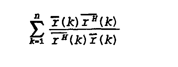
een eigenwaardespreiding heeft die na zo min mogelijk stappen een waardeheeft van althans nagenoeg gelijk aan 1.has an equity spread that has a value of at least almost equal to 1 after as few steps as possible.
Door het gebruik van een combinatie van een projectiealgoritme enhet selecteren van het referentiesignaal op de hierboven gedefinieerdewijze wordt in de praktijk een snellere convergentie bereikt dan volgensde stand van de techniek mogelijk is.By using a combination of a projection algorithm and selecting the reference signal in the manner defined above, convergence is achieved in practice faster than is possible in the prior art.
Bij voorkeur betreft het systeem volgens de uitvinding een meerka-naalssysteem dat wil zeggen een systeem, waarin de ophefgenereermiddelenuit diverse ophefgenereereenheden bestaan en de sensormiddelen uit di¬verse sensoreenheden, waarbij de stuureenheid is voorzien van middelenvoor het actualiseren van coëfficiënten van het digitale filter volgensde volgende recursieve betrekking:Preferably, the system according to the invention relates to a multichannel system, that is to say a system in which the cancellation generating means consist of various cancellation generating units and the sensor means consist of various sensor units, the control unit being provided with means for updating coefficients of the digital filter according to the following recursive relation:

met: θ_ (k) een L-dimensionele filtercoëfficiëntenvector, als er L op-hefsignaalgeneratoren aanwezig zijn;γ = stapgrootteparameter;with: θ_ (k) an L-dimensional filter coefficient vector, if L cancel signal generators are present, γ = step size parameter;
Rv(k) een LxM matrix die als elementen ingangssignalen rv 1 m(k)bevat, als er M sensoren aanwezig zijn; e(k) = foutsignaalvector met M elementen afkomstig van de M senso¬ren.Rv (k) an LxM matrix which contains input signals rv 1 m (k) as elements, if M sensors are present; e (k) = error signal vector with M elements from the M sensors.
In een uitvoeringsvorm voor een enkelkanaalssysteem heeft het sys¬teem volgens de uitvinding het kenmerk, dat - de middelen voor het genereren van het referentiesignaal zijningericht voor het genereren van het volgende referentiesignaal:In an embodiment for a single channel system, the system according to the invention is characterized in that - the means for generating the reference signal are arranged for generating the following reference signal:

met:with:

- de actualiseringseenheid is voorzien van middelen om het actuali-seringssignaal als volgt te berekenen:- the updating unit is provided with means to calculate the updating signal as follows:
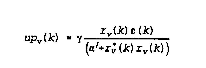
met: γ = stapgrootte «' = kleine constante ter vermijding van een deling door 0; - de stuureenheid is voorzien van middelen om de filtercoëffici-enten als volgt te berekenen:with: γ = step size «'= small constant to avoid division by 0; - the control unit is equipped with means to calculate the filter coefficients as follows:

Voorts kan het systeem volgens de uitvinding schattingsmiddelenomvatten voor het schatten van de overdrachtsfunctie van het secundairetraject die een ingang hebben verbonden met de sensormiddelen en eenuitgang hebben verbonden met de aanpassingseenheid voor het versturenvan een uitgangssignaal voor het actualiseren van de in de aanpassings¬eenheid gebruikte overdrachtsfunctie.Furthermore, the system according to the invention may include estimators for estimating the transfer function of the secondary path that have an input connected to the sensor means and an output connected to the adaptation unit for sending an output signal for updating the transfer function used in the adaptation unit.
De stuureenheid, de actualiseringsmiddelen en de aanpassingseenheiden de eventueel toegepaste schattingsmiddelen kunnen tezamen in softwarevan een computer zijn geïmplementeerd.The control unit, the updating means and the adapting units and any estimating means used may be implemented together in software of a computer.
De ophefgenereermiddelen kunnen zijn geselecteerd uit de volgendemiddelen: tenminste één luidspreker, tenminste één trillingsgenerator, ten¬minste één regelbare stromings-geïnduceerde geluidsbron of een combina¬tie daarvan en de sensormiddelen kunnen zijn geselecteerd uit de vol¬gende middelen: tenminste één geluidsdruksensor, tenminste één trillingsopnemer ofeen combinatie daarvan.The cancellation means may be selected from the following means: at least one loudspeaker, at least one vibration generator, at least one controllable flow-induced sound source or a combination thereof, and the sensor means may be selected from the following means: at least one sound pressure sensor, at least one vibration sensor or a combination thereof.
De uitvinding zal hierna nader worden toegelicht aan de hand vanenkele uitvoeringsvoorbeelden, die zijn bedoeld ter illustratie van hetprincipe van de uitvinding en niet ter beperking daarvan.The invention will be explained in more detail below with reference to a few embodiments, which are intended to illustrate the principle of the invention and not to limit it.
Figuur 1 toont een blokschema van een bekend anti-geluidsysteem;Figuur 2 toont een voorbeeld van blokschema van een anti-geluidsys¬teem volgens de uitvinding.Figure 1 shows a block diagram of a known anti-noise system, Figure 2 shows an example block diagram of an anti-noise system according to the invention.
Uit de wiskunde is het volgende bekend. Stel er is een primairefunctie P(n):The following is known from mathematics. Suppose there is a primary function P (n):
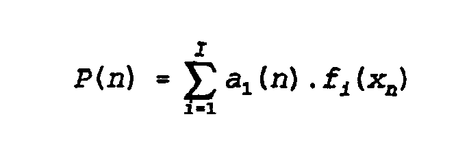
(1) met: a..(n) = vermenigvuldigingscoëfficiënt f.j(xn) = een bekende functie met een variabele xni = 1, 2, 3, ..., I, waarbij I een vooraf bepaalde waarde heeftWil men de diverse a^n) berekenen uit een aantal metingen van xn danmoet aan een aantal voorwaarden zijn voldaan. Ten eerste moet gelden: Is n en ten tweede moeten de diverse a^n) stationair zijn. Dan kunnen dediverse a..(n) worden berekend met de kleinste kwadraten methode. Daar¬voor zijn evenveel stappen nodig als er coëfficiënten a^n) zijn.(1) with: a .. (n) = multiplication coefficient fj (xn) = a known function with a variable xni = 1, 2, 3, ..., I, where I has a predetermined value. n) calculating from a number of measurements of xn, a number of conditions must be met. The first must be: Is n and second, the various a ^ n) must be stationary. Then the various a .. (n) can be calculated with the least squares method. This requires as many steps as there are coefficients a ^ n).
Is echter P vervuild met ruis, dan kan de kleinste kwadraten metho¬de niet worden toegepast. Gelden de beide andere boven genoemde voor¬waarden wel, dan kan de kleinste kwadraten foutmethode worden gebruikt.Voorts kunnen soms grote matrices in de berekeningen voorkomen, die derekentijd van een gebruikte rekeneenheid zwaar belasten, en is de pri¬maire functie P(n) lang niet altijd beschikbaar, zoals in anti-geluid-systemen. Indien dit het geval is, zou de recursieve kleinste kwadratenfoutmethode kunnen worden toegepast. Als de coëfficiënten ai(n) zelfniet tijd-invariant zijn kan de kleinste kwadraten methode in het geheelniet worden toegepast.However, if P is polluted with noise, the least squares method cannot be used. If the other two conditions mentioned above do apply, the least squares error method can be used. In addition, large arrays can sometimes occur in the calculations, which place a heavy burden on the calculation time of a used calculation unit, and the primary function is P (n). by no means always available, as in anti-noise systems. If so, the recursive least squares error method could be used. If the coefficients ai (n) are not time-invariant themselves, the least squares method cannot be applied at all.
Mocht P vervuild zijn met ruis, in de berekening een bijzondergrote matrix voorkomen en mochten de coëfficiënten a^Cn) zelf niet tijd-invariant zijn, dan kan, zoals op zich uit de wiskunde bekend is, metsucces het zogenaamde "projectie-algoritme" worden toegepast. Door eenprojectie-algoritme tezamen met orthogonale functies te gebruiken kunnende I coëfficiënten a^n) zelfs in n stappen worden geschat. Een directetoepassing van een projectie-algoritme met orthogonale functies in eensysteem voor het produceren van bijvoorbeeld anti-geluid is niet moge¬lijk zonder de nodige aanpassingen, omdat het door het anti-geluid afge¬legde traject (het "secundaire traject") faseverschuivingen en tijdver-tragingen introduceert. Bovendien worden in het algemeen geen orthogona¬le functies aan het systeem aangeboden. De noodzakelijke aanpassingen van een projectie-algoritme met orthogonale functies voor bijvoorbeeldeen anti-geluidsysteem zullen hieronder zullen worden toegelicht. Daar¬uit zal blijken, dat in de praktijk het definiëren van orthogonale func¬ties vaak te veel rekentijd in beslag neemt en een benadering van deideale toestand -d.w.z. het gebruik van een projectie-algoritme metorthogonale functies- de voorkeur verdient.If P is contaminated with noise, a particularly large matrix occurs in the calculation and if the coefficients a ^ Cn) are not time-invariant themselves, then, as is known per se from mathematics, the so-called "projection algorithm" can be successfully used. applied. By using a projection algorithm together with orthogonal functions, the I coefficients a ^ n) can even be estimated in n steps. A direct application of a projection algorithm with orthogonal functions in a system for producing anti-noise, for example, is not possible without the necessary adjustments, because the anti-noise trajectory (the "secondary trajectory") traverses phase and introduces time delays. In addition, generally no orthogonal functions are offered to the system. The necessary adaptations of a projection algorithm with orthogonal functions for an anti-noise system, for example, will be explained below. It will be apparent from this that in practice the definition of orthogonal functions often takes too much computing time and an approximation of the ideal condition, i.e. the use of a projection algorithm with orthogonal functions is preferred.
Figuur 1 toont een bekend model van een anti-geluidsysteem. Eenreferentiesignaal f(k) wordt opgewekt door een referentiesignaalgenera-tor 8 en wordt toegevoerd aan een stuureenheid 1, dat een ophefstuursig¬naal s(k) berekent. Het ophefstuursignaal wordt via geschikte verbin¬dingsmiddelen naar een ophefsignaalgenerator 2 geleid, die een ophefsig-naal genereert, dat na passage door een secundaire traject met over¬drachtsfunctie H als procesuitgangssignaal ys(k) in een bepaald gebied 3aankomt, waar het door optelling een primair signaal yp(k) dient op teheffen. Het na de optelling ontstane signaal -het residusignaal yr^-wordt gedetekteerd met behulp van een sensor 4, die een uitgangssignaale(k) toevoert aan actualiseringsmiddelen 5. De actualiseringsmiddelen 5ontvangen tevens het referentiesignaal φ(k) en produceren een actualise-ringssignaal up(k), dat wordt toegevoerd aan de stuureenheid 1 en aldaarwordt gebruikt om de filtercoëfficiënten van een toegepast filter teactualiseren.Figure 1 shows a known model of an anti-noise system. A reference signal f (k) is generated by a reference signal generator 8 and is supplied to a control unit 1, which calculates an override control signal s (k). The lift control signal is fed via suitable connection means to a lift signal generator 2, which generates a lift signal which, after passing through a secondary path with transfer function H, arrives in a specific area 3 as process output signal ys (k), where it adds a primary signal yp (k) should cancel. The signal generated after the addition - the residual signal yr ^ - is detected by means of a sensor 4, which supplies an output signal e (k) to updating means 5. The updating means 5 also receive the reference signal φ (k) and produce an updating signal up ( k), which is supplied to the control unit 1 and used there to update the filter coefficients of an applied filter.
In een meerkanaalssysteem zijn er diverse ophefsignaalgeneratoren 2en diverse sensoren 4 aanwezig.In a multichannel system, there are several cancellation signal generators 2 and various sensors 4 present.
Het primaire signaal yp(k) kan worden gemodelleerd als een afgelei¬de van het referentiesignaal <p(k), waarbij dit laatste signaal een pri¬mair traject met primaire overdrachtsfunctie Hp doorloopt. Stel dat hetreferentiesignaal φ(k) met voldoende nauwkeurigheid kan worden weergege¬ven door N frequentiecomponenten, dan kan φ(k) als enkelvoudig referen¬tiesignaal in het complexe vlak als volgt worden weergegeven:The primary signal yp (k) can be modeled as a derivative of the reference signal <p (k), the latter signal going through a primary path with primary transfer function Hp. Suppose that the reference signal φ (k) can be represented with sufficient accuracy by N frequency components, then φ (k) can be represented as a single reference signal in the complex plane as follows:

(2) met: $(k) = referentiesignaal op tijdstip kAt fv = een frequentiecomponent(2) with: $ (k) = reference signal at time kAt fv = a frequency component
Het primaire signaal yp(k) zal het primaire traject hebben doorlo¬pen alvorens bij punt 3 te zijn aangekomen. Indien nu voor een bij hetprimaire traject behorend primair proces en voor de stuureenheid 1 eeneindige impulsresponsie van lengte I kan worden gebruikt, dan kunnen zowel het primaire signaal yp(k) als het ophef stuursignaal s(k) alslineaire combinaties van opeenvolgende signalen 9(k), q>(k-1) ... *>(k-1+1) worden weergegeven. De ingangselementen kunnen worden verzameld ineen tijdvector <pt(k):The primary signal yp (k) will have passed through the primary trajectory before arriving at point 3. If a primary impulse response of length I can now be used for a primary process associated with the primary section and for the control unit 1, both the primary signal yp (k) and the cancellation control signal s (k) as linear combinations of successive signals 9 (k ), q> (k-1) ... *> (k-1 + 1) are displayed. The input elements can be collected in a time vector <pt (k):

(3)(3)
Het filter dat in de stuureenheid 1 wordt toegepast gebaseerd op eeneindige impulsresponsie wordt meestal een transversaal filter genoemd.The filter used in the controller 1 based on a finite impulse response is usually referred to as a transverse filter.
De referentiesignalen kunnen ook anders worden gedefinieerd. Erkunnen namelijk onafhankelijke golfvormgeneratoren worden toegepast omdiverse referentiesignalen te genereren. De ingangssignalen voor hetprimaire proces met overdrachtsfunctie Hp en de stuureenheid zijn danmeerdimensioneel. Stel dat het primaire signaal I frequentiecomponentenv = 1,...1 omvat, dan bevatten het primaire signaal yp(k) en het ophef-stuursignaal s(k) een lineaire combinatie met complexe coëfficiënten vande volgende tijdfuncties in het complexe vlak:The reference signals can also be defined differently. Namely, independent waveform generators can be used to generate various reference signals. The input signals for the primary process with transfer function Hp and the control unit are then multidimensional. Suppose the primary signal I comprises frequency components v = 1, ... 1, then the primary signal yp (k) and the cancellation control signal s (k) contain a linear combination with complex coefficients of the following time functions in the complex plane:

(4) hetgeen de functies zijn waarop een Fourier-transformatie kan wordengebaseerd. De genoemde complexe coëfficiënten zijn dan Fourier-coëffi-ciënten. Aldus kunnen de ingangselementen ook worden gemodelleerd alseen "Fourier-vector":(4) which are the functions on which a Fourier transform can be based. The said complex coefficients are then Fourier coefficients. Thus, the input elements can also be modeled as a "Fourier vector":

(5)(5)
Een stuureenheid die op formule (5) is gebaseerd kan een Fourier-stuureenheid worden genoemd.A control unit based on formula (5) can be called a Fourier control unit.
Wil het eerder genoemde projectiealgoritme met orthogonale functiestoepasbaar zijn, dan zullen twee opeenvolgende referentievectoren vol¬gens formule (3) of (5) (dus voor bijvoorbeeld k=j en k=j + 1) steedsorthogonaal moeten zijn. Voor een algoritme dat is gebaseerd op referen¬tiesignalen die zijn gedefinieerd volgens formule (3) is het bijna nooitmogelijk om opeenvolgende tijdvectoren <pt(k) orthogonaal te maken. Voortwee opeenvolgende Fourier-vectoren <pf (k) zoals gedefinieerd in formule(5) is dit in principe wel mogelijk. Dit kost in de praktijk echter zeerveel rekentijd en zou het doel van snelle convergentie niet dienen. Dit laatste geldt in het bijzonder wanneer het orthogonaliseren wordt gedaanin het bekende "gefilterde-x" Least Mean Square algoritme (zie voordetails daarvan: B. Widrow en S.D. Stearns, "Adaptive Signal Proces¬sing", Englewood Cliffs, Prentice Hall, 1985; S.J. Elliott, I.M. Stot-hers en P.A. Nelson, "A multiple error LMS algorithm and its applicationto the active control of sound and vibration", IEEE Trans. Acoust.,Speech, Signal Processing, Vol. ASSP 35, pp. 1423-1434, Oct. 1987; enL.J. Eriksson, M.C. Allie en R.A. Greiner, "The selection and applicati¬on of an HR adaptive filter for use in active sound attenuation", IEEETrans. Acoust., Speech, Signal Processing, Vol. ASSP 35, pp. 433-437,April 1987).For the aforementioned projection algorithm with orthogonal function to be applicable, two consecutive reference vectors according to formula (3) or (5) (i.e. for k = j and k = j + 1) must always be orthogonal. For an algorithm based on reference signals defined according to formula (3) it is almost never possible to make consecutive time vectors <pt (k) orthogonal. For two consecutive Fourier vectors <pf (k) as defined in formula (5) this is in principle possible. However, this takes a lot of computing time in practice and would not serve the purpose of rapid convergence. The latter is especially true when orthogonalization is done in the well-known "filtered-x" Least Mean Square algorithm (see for details thereof: B. Widrow and SD Stearns, "Adaptive Signal Processing", Englewood Cliffs, Prentice Hall, 1985; SJ Elliott, IM Stot-hers and PA Nelson, "A multiple error LMS algorithm and its applicationto the active control of sound and vibration", IEEE Trans. Acoust., Speech, Signal Processing, Vol. ASSP 35, pp. 1423-1434 , Oct. 1987; and L.J. Eriksson, MC Allie and RA Greiner, "The selection and applications of an HR adaptive filter for use in active sound attenuation", IEEETrans. Acoust., Speech, Signal Processing, Vol. ASSP 35, pp. 433-437, April 1987).
Het probleem van te veel rekentijd kan worden vermeden door dereferentievectoren zodanig te kiezen of modificeren, dat de eigenwaar-despreiding van een ingangscorrelatiematrix voor de actualiseringsmidde-len 5 na zo min mogelijk stappen, die nodig zijn voor het berekenen vande filtercoëfficiënten van het in de stuureenheid aanwezige filter,althans nagenoeg gelijk aan 1 is geworden, ook al zal dat in meer stap¬pen gebeuren dan bij een orthogonaal stelsel referentievectoren. Dit zalhieronder nader worden toegelicht.The problem of too much computing time can be avoided by choosing or modifying the reference vectors such that the eigenvalue spread of an input correlation matrix for the updating means 5 after as few steps as possible are needed to calculate the filter coefficients of the controller. filter present, has at least become equal to 1, even if this will be done in more steps than with an orthogonal system of reference vectors. This will be explained in more detail below.
Bij een reeks referentievectoren <pt(k) (k = 1, 2, ...), zoals gede¬finieerd in formule (3), blijkt een dergelijke eigenwaardespreidingmeestal verre van optimaal te zijn. Dat geldt vaak zelfs nog na duizen¬den stappen van het toegepaste algoritme. Het blijkt echter dat, indienwordt uitgegaan van formule (5) en de reeks referentievectoren q>f(k) (k= 1, 2, ...) zoals gedefinieerd in formule (4), de eigenwaardespreidingvan de autocorrelatiematrix na 1 periode van het signaal reeds gelijkaan is 1.With a series of reference vectors <pt (k) (k = 1, 2, ...), as defined in formula (3), such an eigenvalue spread usually proves to be far from optimal. This often applies even after thousands of steps of the applied algorithm. However, it appears that, assuming formula (5) and the set of reference vectors q> f (k) (k = 1, 2, ...) as defined in formula (4), the eigenvalue spread of the autocorrelation matrix after 1 period of the signal is already equal 1.
Nu zal het voorkeursalgoritme worden afgeleid voor een enkel ka-naals-anti-geluidsysteem en onder de voorwaarden, dat zowel het primaireproces als het secundaire proces lineair is.Now the preferred algorithm will be derived for a single channel anti-noise system and under the conditions that both the primary process and the secondary process are linear.
Het ophefstuursignaal s(k) (k = 1, 2, ..., n) kan worden geschreven als:The override control signal s (k) (k = 1, 2, ..., n) can be written as:

(6) waarin "H" duidt op de getransponeerde van de geconjugeerde van de com¬plexe vector, 9H(k) de vector is die de ingangswaarden voor de stuureen¬heid 1 omvat en 8c(k-1) de vector is die de meest recente filtercoëffi¬ciënten van de stuureenheid 1 omvat.(6) where "H" denotes the transpose of the conjugate of the complex vector, 9H (k) is the vector comprising the input values for the controller 1 and 8c (k-1) is the vector which represents the most recent filter coefficients of the controller 1.
Neem aan aar net tijdinvariante secundaire proces Kan worden gemo¬delleerd als een eindige impulsresponsie (FIR) met coëfficiënten h,, danAssume the time-invariant secondary process Can be modeled as a finite impulse response (FIR) with coefficients h ,, then
JJ
kan het uitgangssignaal ys(k) van het secundaire proces worden geschre¬ven als een convolutie van het ophef stuursignaal s(k) en de eindigeimpulsresponsie h.:the output signal ys (k) of the secondary process can be written as a convolution of the cancellation control signal s (k) and the finite impulse response h .:
JJ
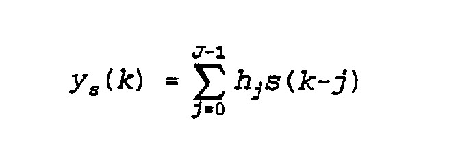
(7)(7)
Voor een ideale sensor 4 geldt: de gemeten fout e(k) = yp(k) +ys(k), zodat voor een tijdvertragingsstuureenheid de fout ε (k) kan wor¬den geschreven als:For an ideal sensor 4, the measured error e (k) = yp (k) + ys (k), so that for a time delay control unit the error ε (k) can be written as:

(8)(8)
Hierin duidt op de complexe geconjugeerde van de betreffende vector.Voor een op vergelijking (5) gebaseerde Fourier-stuureenheid kan de foute(k) worden geschreven als:This denotes the complex conjugate of the vector in question. For a Fourier control unit based on Equation (5), the error (k) can be written as:
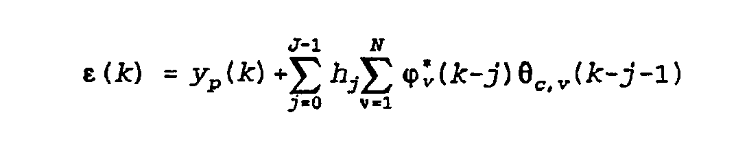
(9)(9)
Om het schattingsproces te vereenvoudigen wordt gebruik gemaakt vande eerder genoemde, op zich zelf bekende gefilterde-x-configuratie.Daarbij wordt er van uit gegaan, dat indien de stapgrootteparameter γklein wordt gekozen, de verandering in de geschatte filtercoëfficiëntengering is gedurende de lengte van de eindige impulsresponsie (gedurendeJ monsters). Dan geldt met andere woorden:To simplify the estimation process, use is made of the aforementioned filtered-x configuration known per se, assuming that if the step size parameter γsmall is chosen, the change in the estimated filter coefficient ring is the length of the finite impulse response (during samples). In other words:

(10)(10)
Uitgaande van formule (10) kan de fout e(k) bij gebruik van een tijdver¬tragingsstuureenheid worden geschreven als: en bij gebruik van een Fourier-stuureenheid:Starting from formula (10), the error e (k) when using a time delay control unit can be written as: and when using a Fourier control unit:
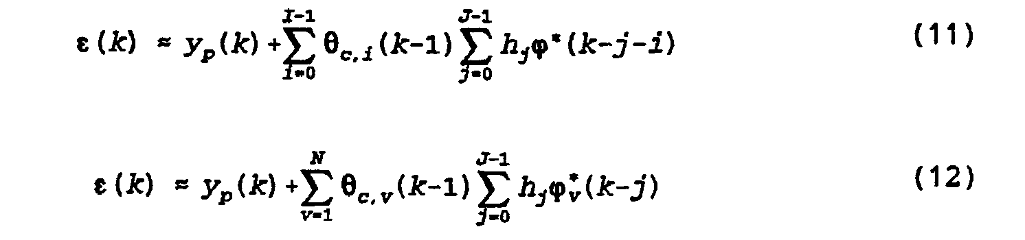
Vergelijkingen (11) en (12) kunnen ook worden geschreven in de volgendevectornotatie:Equations (11) and (12) can also be written in the following vector notation:

waarin de componenten van de vector P*(k) voor het geval van een tijd-vertragingsstuureenheid gelijk zijn aan de waarde gedefinieerd in formu¬le (14) en in het geval van een Fourier-stuureenheid aan de waarde gede¬finieerd in formule (15):wherein the components of the vector P * (k) for the case of a time delay driver are equal to the value defined in formula (14) and in the case of a Fourier driver to the value defined in formula ( 15):

De vector P^k) wordt het gefilterde-x-signaal genoemd.The vector P ^ k) is called the filtered-x signal.
Indien het secundaire pad bekend is, wordt het actualiseren van defiltercoëfficiënten bij kleine stapgrootteparameters gereduceerd tot eenalgemeen lineaire besturingsconfiguratie. Indien nu het op zich zelfbekende projectiealgoritme wordt toegepast op de bovengenoemde gefilter-de-x-configuratie kan het volgende algoritme voor het actualiseren vande filtercoëfficiënten worden afgeleid:If the secondary path is known, updating the filter coefficients at small step size parameters is reduced to a generally linear control configuration. If now the self-known projection algorithm is applied to the above filtered-the-x configuration, the following algorithm for updating the filter coefficients can be derived:

met: 6c(k) = filtercoëfficiëntenvector op "tijdstip" kγ = stapgrootteparameterwith: 6c (k) = filter coefficient vector at "time" kγ = step size parameter
Het actualiseren van de filtercoëfficiënten met behulp van algorit¬me (16) kan worden geïmplementeerd met behulp van het in figuur 2 weer¬gegeven schema. In figuur 2 verwijzen dezelfde verwijzingscijfers naardezelfde elementen als in figuur 1. In plaats van een referentiesignaalΦ(k) is direct verwezen naar een referentiesignaalvector $(k), zoalsgedefinieerd in ofwel formule (3) ofwel formule (5). Voorts is in plaatsvan een enkel actualiseringssignaal up(k) een actualiseringsvector üp(k)weergegeven, waarin alle actualiseringssignalen voor alle filtercoëffi¬ciënten van de stuureenheid 1 zijn opgenomen. Tussen het referentiesig¬naal f*(k) en de ingang van de actualiseringseenheid 5 is een aanpas-singseenheid 7 toegevoegd. De aanpassingseenheid 7 past het aan de actu¬aliseringseenheid 5 toegevoerde referentiesignaal φ*(k) aan volgens debewerking van formule (14), respectievelijk (15), afhankelijk daarvan ofhet referentiesignaal is gedefinieerd volgens formule (3), respectieve¬lijk (5). Het aan de actualiseringseenheid toegevoerde signaal is hetgefilterde-x-signaal r*(k). Aan de hand van dit gefilterde-x-signaalr*(k) berekent de actualiseringseenheid een actualiseringssignaal up(k)volgens de volgende formule:Updating the filter coefficients using algorithm (16) can be implemented using the scheme shown in Figure 2. In Figure 2, the same reference numerals refer to the same elements as in Figure 1. Instead of a reference signal Φ (k), reference is made directly to a reference signal vector $ (k), as defined in either formula (3) or formula (5). Furthermore, instead of a single update signal up (k), an update vector üp (k) is shown, in which all update signals for all filter coefficients of the control unit 1 are included. An adaptation unit 7 is added between the reference signal f * (k) and the input of the update unit 5. The adaptation unit 7 adjusts the reference signal φ * (k) applied to the actuation unit 5 according to the processing of formula (14) and (15), respectively, depending on whether the reference signal is defined according to formula (3), respectively (5) . The signal applied to the updating unit is the filtered x signal r * (k). Based on this filtered-x signal r * (k), the updating unit calculates an updating signal up (k) according to the following formula:

De genormaliseerde ingangscorrelatiematrix in deze gefilterde-x-configuratie is gelijk aan (k = 1, 2, ..., n):The normalized input correlation matrix in this filtered-x configuration is equal to (k = 1, 2, ..., n):

Nu blijkt dat de eigenwaardespreiding van deze autocorrelatiematrixnog sterk afhangt van de ingangsvectoren. Voor een tijdvertragingsstuur-eenheid is optimalisatie in het algemeen lastig. Voor een Fourier-stuur-eenheid kan de matrix volgens formule (17) echter eenvoudig worden geop¬timaliseerd, indien de matrix een diagonaalmatrix zou zijn, dus indienalle niet op de diagonaal liggende elementen van de matrix klein zoudenzijn ten opzichte van de diagonaalelementen. Aan deze voorwaarde wordtvoldaan indien twee willekeurige componenten van de ingangsvector steedsonafhankelijk zijn. Het is aannemelijk dat voor een Fourier-stuureenheid na enkele stappen van de berekening de niet op de diagonaal liggendeelementen van de matrix (17) verwaarloosbaar klein zijn geworden tenopzichte van de diagonaalelementen, zodat in dat geval de matrix (17) ingoede benadering een diagonaalmatrix is. De eigenwaardespreiding van dematrix (17) zal dan althans nagenoeg gelijk zijn aan 1, als de componen¬ten θ„ (k) van de vector 0„(k) in het actualiseringsalgoritme volgensformule (16) worden geschaald met de volgende factor:It now appears that the eigenvalue distribution of this autocorrelation matrix still strongly depends on the input vectors. For a time delay control unit, optimization is generally difficult. For a Fourier control unit, however, the matrix of formula (17) can be easily optimized if the matrix were a diagonal matrix, so if all of the diagonal elements of the matrix were not small relative to the diagonal elements. This condition is met if any two components of the input vector are always independent. It is plausible that for a Fourier control unit after a few steps of the calculation the non-diagonal elements of the matrix (17) have become negligibly small compared to the diagonal elements, so that in this case the matrix (17) is an approximate diagonal matrix . The eigenvalue spread of the matrix (17) will then be at least virtually equal to 1, if the components θ „(k) of the vector 0„ (k) in the update algorithm according to formula (16) are scaled by the following factor:

Gebruik van formule (18) resulteert in de volgende recursieve betrekkingvoor het berekenen van de filtercoëfficiënten 6C v(k):Using formula (18) results in the following recursive relationship for calculating the filter coefficients 6C v (k):

waarin: «' een kleine constante is ter vermijding van deling door 0.where: «'is a small constant to avoid division by 0.
Bij implementatie van het algoritme volgens formule (19) dient hetreële deel te worden gescheiden van het imaginaire deel. Indien slechtséén filtercoëfficiënt 6c(k) zou hoeven te worden berekend, wordt algo¬ritme (19) gereduceerd tot:When the algorithm according to formula (19) is implemented, the real part must be separated from the imaginary part. If only one filter coefficient 6c (k) is to be calculated, algorithm (19) is reduced to:

Bij meerdere ingangssignalen geldt algoritme (20) voor alleöc,v<k>·With multiple input signals, algorithm (20) applies to alleoc, v <k>
Voor meerkanaalssystemen, dat wil zeggen systemen waarin diverseophefsignaalgeneratoren 2 en diverse sensoren 4 worden toegepast, kaneen soortgelijk algoritme worden afgeleid voor het actualiseren van defiltercoëfficiënten in de stuureenheid 1. Voor een meerkanaalssysteemkan de volgende recursieve betrekking voor de filtercoëfficiënten(k) worden afgeleid:For multichannel systems, i.e. systems employing various lift signal generators 2 and various sensors 4, a similar algorithm can be derived for updating the filter coefficients in the controller 1. For a multichannel system, the following recursive relationship for the filter coefficients (k) can be derived:
C, VRESUME
met: 6cv(k) een L-dimensionele filtercoëfficiëntenvector, als er L op-hefsignaalgeneratoren 2 aanwezig zijn;γ = stapgrootteparameter;with: 6cv (k) an L-dimensional filter coefficient vector, if L cancel signal generators 2 are present, γ = step size parameter;

R^k) een LxM matrix die als elementen ingangssignalen rv ^ m(k)bevat, als er M sensoren 4 aanwezig zijn; e(k) = foutsignaalvector met M elementen afkomstig van de M senso¬ren 4.R ^ k) an LxM matrix which contains input signals rv ^ m (k) as elements, if M sensors 4 are present; e (k) = error signal vector with M elements from the M sensors 4.
Er kan worden aangetoond dat ook voor het meerkanaalsalgoritmevolgens formule (21) de convergentiesnelheid optimaal is en niet afhangtvan de positie van de diverse ophefsignaalgeneratoren 2 en de diversesensoren 4.It can be shown that also for the multichannel algorithm according to formula (21), the convergence speed is optimal and does not depend on the position of the various cancel signal generators 2 and the various sensors 4.
In het bovenstaande is er van uit gegaan, dat de overdrachtsfunctieH van het secundaire traject bekend en stationair is. In werkelijkheidis het secundaire traject lang niet altijd stationair, hetgeen met zichmee brengt, dat de componenten h, van de overdrachtsfunctie H, zoalsIn the above it has been assumed that the transfer function H of the secondary path is known and stationary. In reality, the secondary path is not always stationary, which means that the components h of the transfer function H, such as
JJ
gebruikt in de aanpassingseenheid 7, niet stationair zijn. Het is moge¬lijk om middelen 6 voor het schatten van de overdrachtsfunctie op hetmoment van actualiseren van de filtercoëfficiënten in het schema op tenemen. Deze schattingsmiddelen 6 kunnen worden aangebracht zoals weerge¬geven in figuur 2, namelijk met een ingang verbonden met de sensor 4 eneen uitgang verbonden met de aanpassingseenheid 7 voor het actualiserenvan de componenten h^ van de overdrachtsfunctie H. Zulke middelen zijnaan de deskundige bekend en behoeven hier geen nadere toelichting (ziebijvoorbeeld het Amerikaanse octrooischrift 4.878.188).used in the adjustment unit 7, not be stationary. It is possible to include means 6 for estimating the transfer function at the time of updating the filter coefficients in the schematic. These estimating means 6 can be provided as shown in figure 2, namely with an input connected to the sensor 4 and an output connected to the adaptation unit 7 for updating the components h of the transfer function H. Such means are known to the skilled person and require no further explanation here (see, for example, U.S. Patent No. 4,878,188).
Het zal aan een deskundige duidelijk zijn, dat de stuureenheid 1,de actualiseringseenheid 5, de schattingseenheid 6 (indien toegepast) ende aanpassingseenheid 7 tezamen in software van een computer kunnen zijngeïmplementeerd.It will be apparent to one skilled in the art that the controller 1, the updating unit 5, the estimating unit 6 (if used) and the adapting unit 7 may be implemented together in software of a computer.
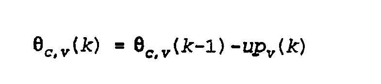
Claims (7)



Priority Applications (8)
| Application Number | Priority Date | Filing Date | Title |
|---|---|---|---|
| NL9302013A NL9302013A (en) | 1993-11-19 | 1993-11-19 | System for rapid convergence of an adaptive filter when generating a time-variant signal to cancel a primary signal. |
| DK94203358T DK0654901T3 (en) | 1993-11-19 | 1994-11-17 | Rapid convergence system of a custom filter in generating a time-varying signal for canceling a prime |
| DE69420232T DE69420232T2 (en) | 1993-11-19 | 1994-11-17 | Fast convergence system of an adaptive filter to generate a time-dependent signal to compensate for a primary signal |
| EP94203358A EP0654901B1 (en) | 1993-11-19 | 1994-11-17 | System for the rapid convergence of an adaptive filter in the generation of a time variant signal for cancellation of a primary signal |
| ES94203358T ES2136158T3 (en) | 1993-11-19 | 1994-11-17 | SYSTEM FOR THE QUICK CONVERGENCE OF AN ADAPTIVE FILTER FOR THE GENERATION OF A VARIABLE SIGNAL IN TIME FOR THE CANCELLATION OF A PRIMARY SIGNAL. |
| AT94203358T ATE183861T1 (en) | 1993-11-19 | 1994-11-17 | FAST CONVERGENCE SYSTEM OF AN ADAPTIVE FILTER FOR GENERATING A TIME-DEPENDENT SIGNAL TO COMPENSATE A PRIMARY SIGNAL |
| US08/344,588 US5577127A (en) | 1993-11-19 | 1994-11-18 | System for rapid convergence of an adaptive filter in the generation of a time variant signal for cancellation of a primary signal |
| GR990402002T GR3030971T3 (en) | 1993-11-19 | 1999-08-26 | System for the rapid convergence of an adaptive filter in the generation of a time variant signal for cancellation of a primary signal. |
Applications Claiming Priority (2)
| Application Number | Priority Date | Filing Date | Title |
|---|---|---|---|
| NL9302013A NL9302013A (en) | 1993-11-19 | 1993-11-19 | System for rapid convergence of an adaptive filter when generating a time-variant signal to cancel a primary signal. |
| NL9302013 | 1993-11-19 |
Publications (1)
| Publication Number | Publication Date |
|---|---|
| NL9302013A true NL9302013A (en) | 1995-06-16 |
Family
ID=19863162
Family Applications (1)
| Application Number | Title | Priority Date | Filing Date |
|---|---|---|---|
| NL9302013A NL9302013A (en) | 1993-11-19 | 1993-11-19 | System for rapid convergence of an adaptive filter when generating a time-variant signal to cancel a primary signal. |
Country Status (8)
| Country | Link |
|---|---|
| US (1) | US5577127A (en) |
| EP (1) | EP0654901B1 (en) |
| AT (1) | ATE183861T1 (en) |
| DE (1) | DE69420232T2 (en) |
| DK (1) | DK0654901T3 (en) |
| ES (1) | ES2136158T3 (en) |
| GR (1) | GR3030971T3 (en) |
| NL (1) | NL9302013A (en) |
Families Citing this family (18)
| Publication number | Priority date | Publication date | Assignee | Title |
|---|---|---|---|---|
| DE4421853A1 (en) * | 1994-06-22 | 1996-01-04 | Philips Patentverwaltung | Mobile terminal |
| US5917919A (en) * | 1995-12-04 | 1999-06-29 | Rosenthal; Felix | Method and apparatus for multi-channel active control of noise or vibration or of multi-channel separation of a signal from a noisy environment |
| US5978489A (en) * | 1997-05-05 | 1999-11-02 | Oregon Graduate Institute Of Science And Technology | Multi-actuator system for active sound and vibration cancellation |
| US6094623A (en) * | 1998-03-25 | 2000-07-25 | The Governors Of The University Of Alberta | Non-linear digital adaptive compensation in non-ideal noise environments |
| US6728380B1 (en) | 1999-03-10 | 2004-04-27 | Cummins, Inc. | Adaptive noise suppression system and method |
| WO2001086639A1 (en) * | 2000-05-06 | 2001-11-15 | Nanyang Technological University | System for noise suppression, transceiver and method for noise suppression |
| JP2003532961A (en) * | 2000-05-08 | 2003-11-05 | ネイダーランゼ、オルガニザティー、ボー、トゥーゲパストナトゥールウェテンシャッペルーク、オンダーツォーク、ティーエヌオー | Method of controlling an active control system and system using the method |
| DE10041885A1 (en) * | 2000-08-25 | 2002-03-07 | Mueller Bbm Gmbh | Speech signal transmission system e.g. for motor vehicle hands-free telephone, adjusts filter so that difference signal is minimum for given harmonic frequency |
| US6738481B2 (en) | 2001-01-10 | 2004-05-18 | Ericsson Inc. | Noise reduction apparatus and method |
| DE10135566B4 (en) * | 2001-07-20 | 2009-12-10 | Eads Deutschland Gmbh | Method and system for actively reducing the sound emission of engines |
| US7688984B2 (en) | 2003-11-26 | 2010-03-30 | The Regents Of The University Of California | Active noise control method and apparatus including feedforward and feedback controllers |
| ES2297964B1 (en) * | 2005-03-03 | 2009-08-25 | Angel Carpeño Velayos | SMART INCREMENTAL FILTER. |
| CA2647462C (en) | 2006-04-01 | 2014-05-20 | Widex A/S | Hearing aid, and a method for control of adaptation rate in anti-feedback systems for hearing aids |
| GB2437772B8 (en) * | 2006-04-12 | 2008-09-17 | Wolfson Microelectronics Plc | Digital circuit arrangements for ambient noise-reduction. |
| GB0725114D0 (en) * | 2007-12-21 | 2008-01-30 | Wolfson Microelectronics Plc | Gain calibration based on evice properties |
| US9165549B2 (en) | 2009-05-11 | 2015-10-20 | Koninklijke Philips N.V. | Audio noise cancelling |
| DE102011106647A1 (en) * | 2011-07-05 | 2013-01-10 | J. Eberspächer GmbH & Co. KG | ANTISCHALL SYSTEM FOR EXHAUST SYSTEMS AND METHOD FOR CONTROLLING THE SAME |
| JP6699189B2 (en) * | 2016-01-19 | 2020-05-27 | セイコーエプソン株式会社 | Projector and projector control method |
Citations (1)
| Publication number | Priority date | Publication date | Assignee | Title |
|---|---|---|---|---|
| WO1993015501A1 (en) * | 1992-01-28 | 1993-08-05 | Active Noise And Vibration Technologies Inc. | Active noise cancellation |
Family Cites Families (7)
| Publication number | Priority date | Publication date | Assignee | Title |
|---|---|---|---|---|
| US5170433A (en) * | 1986-10-07 | 1992-12-08 | Adaptive Control Limited | Active vibration control |
| US4815139A (en) * | 1988-03-16 | 1989-03-21 | Nelson Industries, Inc. | Active acoustic attenuation system for higher order mode non-uniform sound field in a duct |
| US4878188A (en) * | 1988-08-30 | 1989-10-31 | Noise Cancellation Tech | Selective active cancellation system for repetitive phenomena |
| US5396561A (en) * | 1990-11-14 | 1995-03-07 | Nelson Industries, Inc. | Active acoustic attenuation and spectral shaping system |
| US5278913A (en) * | 1992-07-28 | 1994-01-11 | Nelson Industries, Inc. | Active acoustic attenuation system with power limiting |
| US5416845A (en) * | 1993-04-27 | 1995-05-16 | Noise Cancellation Technologies, Inc. | Single and multiple channel block adaptive methods and apparatus for active sound and vibration control |
| US5428562A (en) * | 1993-09-03 | 1995-06-27 | At&T Corp. | Fast converging adaptive filter |
-
1993
- 1993-11-19 NL NL9302013A patent/NL9302013A/en not_active Application Discontinuation
-
1994
- 1994-11-17 EP EP94203358A patent/EP0654901B1/en not_active Expired - Lifetime
- 1994-11-17 AT AT94203358T patent/ATE183861T1/en not_active IP Right Cessation
- 1994-11-17 ES ES94203358T patent/ES2136158T3/en not_active Expired - Lifetime
- 1994-11-17 DK DK94203358T patent/DK0654901T3/en active
- 1994-11-17 DE DE69420232T patent/DE69420232T2/en not_active Expired - Lifetime
- 1994-11-18 US US08/344,588 patent/US5577127A/en not_active Expired - Lifetime
-
1999
- 1999-08-26 GR GR990402002T patent/GR3030971T3/en unknown
Patent Citations (1)
| Publication number | Priority date | Publication date | Assignee | Title |
|---|---|---|---|---|
| WO1993015501A1 (en) * | 1992-01-28 | 1993-08-05 | Active Noise And Vibration Technologies Inc. | Active noise cancellation |
Non-Patent Citations (1)
| Title |
|---|
| ICASSP 90; 3-6 APRIL 1990; ALBUQUERQUE, (US); HONG FAN et al : ROBUST ADAPTIVE ALGORITHMS FOR ACTIVE NOISE AND VIBRATION CONTROL; P 1137-1140; * |
Also Published As
| Publication number | Publication date |
|---|---|
| GR3030971T3 (en) | 1999-11-30 |
| EP0654901A1 (en) | 1995-05-24 |
| EP0654901B1 (en) | 1999-08-25 |
| DE69420232T2 (en) | 2000-05-11 |
| DK0654901T3 (en) | 1999-12-13 |
| US5577127A (en) | 1996-11-19 |
| ATE183861T1 (en) | 1999-09-15 |
| DE69420232D1 (en) | 1999-09-30 |
| ES2136158T3 (en) | 1999-11-16 |
Similar Documents
| Publication | Publication Date | Title |
|---|---|---|
| US5691893A (en) | Adaptive control system | |
| US5917919A (en) | Method and apparatus for multi-channel active control of noise or vibration or of multi-channel separation of a signal from a noisy environment | |
| JP3365774B2 (en) | Active controller for noise shaping. | |
| JP6616768B2 (en) | Active noise control system | |
| EP0724415B1 (en) | Single and multiple channel block adaptive methods and apparatus for active sound and vibration control | |
| JP3305719B2 (en) | Method and apparatus for online system identification | |
| EP0654901B1 (en) | System for the rapid convergence of an adaptive filter in the generation of a time variant signal for cancellation of a primary signal | |
| JP7612848B2 (en) | SYSTEM AND METHOD FOR ADAPTING ESTIMATED SECONDARY PATH - Patent application | |
| JPH08227322A (en) | An active noise and vibration control system that calculates a time-varying plant using residual signals to generate a probe signal | |
| WO1994024970A9 (en) | Single and multiple channel block adaptive methods and apparatus for active sound and vibration control | |
| NL9001016A (en) | DIGITAL ECHO COMPENSATOR WITH A DOUBLE-VOICE DETECTOR. | |
| Kim et al. | Active control of multi-tonal noise with reference generator based on on-line frequency estimation | |
| US5812682A (en) | Active vibration control system with multiple inputs | |
| GB2107960A (en) | Method and apparatus for cancelling vibrations | |
| GB2271908A (en) | Adaptive control for a noise cancelling system | |
| JP3646809B2 (en) | Time domain adaptive control system | |
| DE60218265T2 (en) | Active noise cancellation system with frequency response control | |
| EP0805432A2 (en) | Feedback method of noise control having multiple inputs and ouputs | |
| US5559839A (en) | System for the generation of a time variant signal for suppression of a primary signal with minimization of a prediction error | |
| EP0694234B1 (en) | Control system for periodic disturbances | |
| JP3590096B2 (en) | Noise cancellation system | |
| US20250247647A1 (en) | Systems and methods for subband adaptive filtering for enhanced active noise cancellation in vehicles | |
| EP4657429A1 (en) | Systems and methods for virtual microphones in active noise cancellation | |
| KR100212149B1 (en) | An active noise control method based on the lattice structure | |
| WO1992008224A1 (en) | Active vibration control system with multiple inputs |
Legal Events
| Date | Code | Title | Description |
|---|---|---|---|
| A1B | A search report has been drawn up | ||
| BV | The patent application has lapsed |