RU2006830C1 - Device for determining adhesion properties of liquid media - Google Patents
Device for determining adhesion properties of liquid media Download PDFInfo
- Publication number
- RU2006830C1 RU2006830C1 SU4819380A RU2006830C1 RU 2006830 C1 RU2006830 C1 RU 2006830C1 SU 4819380 A SU4819380 A SU 4819380A RU 2006830 C1 RU2006830 C1 RU 2006830C1
- Authority
- RU
- Russia
- Prior art keywords
- pusher
- tear
- core
- winding
- contact
- Prior art date
Links
- 239000007788 liquid Substances 0.000 title claims description 3
- 239000000758 substrate Substances 0.000 claims description 13
- 238000004804 winding Methods 0.000 claims description 12
- 230000001070 adhesive effect Effects 0.000 claims description 11
- 239000000853 adhesive Substances 0.000 claims description 9
- 230000006378 damage Effects 0.000 claims description 7
- 230000001066 destructive effect Effects 0.000 claims description 5
- 239000011521 glass Substances 0.000 claims description 3
- 230000003993 interaction Effects 0.000 claims 1
- 238000005259 measurement Methods 0.000 abstract description 3
- 239000003814 drug Substances 0.000 abstract description 2
- 230000001105 regulatory effect Effects 0.000 abstract description 2
- 230000000694 effects Effects 0.000 abstract 1
- 239000000126 substance Substances 0.000 abstract 1
- 239000000463 material Substances 0.000 description 11
- 239000003990 capacitor Substances 0.000 description 4
- 238000010586 diagram Methods 0.000 description 3
- 230000015572 biosynthetic process Effects 0.000 description 2
- 238000000034 method Methods 0.000 description 2
- 238000000926 separation method Methods 0.000 description 2
- XAGFODPZIPBFFR-UHFFFAOYSA-N aluminium Chemical compound [Al] XAGFODPZIPBFFR-UHFFFAOYSA-N 0.000 description 1
- 229910052782 aluminium Inorganic materials 0.000 description 1
- 239000006059 cover glass Substances 0.000 description 1
- 239000003989 dielectric material Substances 0.000 description 1
- 238000009434 installation Methods 0.000 description 1
- 239000012528 membrane Substances 0.000 description 1
- 210000003097 mucus Anatomy 0.000 description 1
Images

Landscapes
- Push-Button Switches (AREA)
Abstract
Description
Изобретение относится к медицине, может быть использовано для определения адгезионных свойств биологических секретов и других жидких сред и позволяет повысить точность измерений путем обеспечения стабильных режимов давления через отрывной элемент на исследуемый материал и возможности разрушения адгезионного контакта в различных скоростных режимах. The invention relates to medicine, can be used to determine the adhesive properties of biological secrets and other liquid media and can improve the accuracy of measurements by ensuring stable pressure modes through the tear-off element on the material under study and the possibility of breaking the adhesive contact in various speed modes.
Известны устройства для определения силы адгезии методом нормального отрыва, состоящие из отрывного элемента, подложки, разрушающего механизма и силоизмерительной системы. Known devices for determining the adhesion force by the method of normal separation, consisting of a tear-off element, a substrate, a destructive mechanism and a force measuring system.
Однако данные устройства не обеспечивают стабильных по силе и времени режимов давления на исследуемый материал, а также отсутствует возможность регулирования времени разрушения адгезионного контакта, что снижает точность полученных результатов и ведет к невозможности сопоставления данных, полученных при различных режимах работы. Это важно для моделирования ситуации, отражающей зависимость силы отрыва слизи от стенки трахеобронхиального дерева и скорости воздушного потока в нем. However, these devices do not provide pressure and pressure modes that are stable in strength and time for the material under study, and there is no possibility of adjusting the time of destruction of the adhesive contact, which reduces the accuracy of the results and makes it impossible to compare data obtained under different operating conditions. This is important for modeling the situation, reflecting the dependence of the separation force of mucus from the wall of the tracheobronchial tree and the speed of the air flow in it.
Известно устройство для опрделения прочности сцепления соединений, выполненное из пневматической камеры, разделенной на две части гибкой мембраной, толкателя, держателя образца в виде двух коаксиально установленных полых цилиндров, дросселя и источника сжатого воздуха. Устройство также содержит перемычку с винтовой нарезкой, установленную на цилиндре и связывающую его с концом толкателя, шток, размещаемый в отверстии цилиндра и связывающий отрывной элемент с цилиндром. Кроме того, устройство содержит хомут для соединения частей камеры, подставку, крепежные болты для закрепления камеры с измерительной аппаратурой [1] . A device for determining the adhesion strength of joints made of a pneumatic chamber divided into two parts by a flexible membrane, a pusher, a sample holder in the form of two coaxially mounted hollow cylinders, a throttle and a source of compressed air. The device also contains a jumper with a screw thread mounted on the cylinder and connecting it to the end of the pusher, a rod placed in the hole of the cylinder and connecting the tear-off element with the cylinder. In addition, the device contains a clamp for connecting parts of the camera, stand, mounting bolts for securing the camera with measuring equipment [1].
Однако данное устройство не обеспечивает стабильных режимов давления на исследуемый материал и работает в одном скоростном режиме разрушения адгезионного контакта. Это ведет и к искажению результатов и невозможности их сопоставления при работе на различных скоростных режимах разрушения адгезионного контакта и при различных величинах силы и времени давления на исследуемый материал. However, this device does not provide stable pressure conditions for the material under study and operates in the same high-speed mode of destruction of the adhesive contact. This leads to a distortion of the results and the impossibility of comparing them when working at different speed modes of the destruction of the adhesive contact and at different values of the force and time of pressure on the material under study.
Цель изобретения - повышение точности определения адгезионных свойств биологических секретов путем обеспечения стабильных режимов давления через отрывной элемент на исследуемый материал и регулирования времени разрушения адгезионного контакта. The purpose of the invention is to increase the accuracy of determining the adhesion properties of biological secrets by ensuring stable pressure regimes through the tear-off element on the material under study and adjusting the time of destruction of the adhesive contact.
Это достигается тем, что в известном устройстве для определения прочности сцепления соединений, состоящего из разрушающего механизма, подложки, отрывного элемента, толкателя, держателя образца, связанного с толкателем, согласно изобретению дополнительно содержит формирователь напряжения пилообразной формы с регуляцией времени нарастания его амплитуды, который связан с разрушающим механизмом, выполненным в виде кольцевого постоянного магнита с сердечником, на котором помещен толкатель, представленный в виде стакана с обмоткой. This is achieved by the fact that in the known device for determining the adhesion strength of the joints, consisting of a destructive mechanism, a substrate, a tear-off element, a pusher, a sample holder associated with a pusher, according to the invention further comprises a sawtooth voltage shaper with regulation of its amplitude rise time, which is connected with a destructive mechanism made in the form of an annular permanent magnet with a core on which a pusher is placed, presented in the form of a glass with a winding.
Постоянный магнит обеспечивает создание стабильной силы, направленной на перемещение толкателя в магнитном поле и зависящей от силы тока на его обмотке, величина которого регулируется формирователем напряжения, что необходимо для создания стабильных режимов давления на исследуемый материал и регулирования скоростных режимов разрушения адгезионного контакта. A permanent magnet ensures the creation of a stable force aimed at moving the pusher in a magnetic field and depending on the current strength on its winding, the magnitude of which is regulated by the voltage shaper, which is necessary to create stable pressure conditions on the material under study and to regulate the rate of adhesion contact failure.
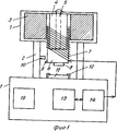
На фиг. 1 показана схема устройства; на фиг. 2 - схема формирователя напряжения пилообразной формы с регуляцией времени нарастания его амплитуды. In FIG. 1 shows a diagram of a device; in FIG. 2 is a diagram of a sawtooth voltage shaper with regulation of the rise time of its amplitude.
Устройство состоит из корпуса прибора 1, выполненного из диэлектрического материала. В корпусе выделяют два блока - верхний и нижний, соединенных между собой стойками 2. В верхнем блоке корпуса 1 размещен постоянный кольцевой магнит 3 с сердечником 4 в центре, закрепленным к верхней панели корпуса 1 винтом 5. На сердечнике 4 расположен толкатель 6 в виде стакана с обмоткой 7, свободно перемещающийся в вертикальном направлении. The device consists of a housing of the
Зазор между стенками толкателя 6 и сердечником 4 равен 0,5 мм. Толкатель должен быть выполнен из легкого прочного материала, например алюминия, с толщиной стенок 0,3 мм, толщиной дна 1 мм. Ко дну толкателя жестко закреплен отрывной элемент 8, представляющий собой толстое покровное стекло, и рычаг 9 концевого переключателя 10, расположенного на стойке 2. The gap between the walls of the
На верхней панели нижнего блока корпуса 1 расположена подложка 11 в виде предметного стекла, вдвигаемого в пазы держателя 12. В нижней части корпуса расположен трансформатор 13 и формирователь напряжения 14 пилообразной формы с регуляцией времени нарастания его амплитуды. Элементы схемы - потенциометр 15, обеспечивающий установку скорости нарастания напряжения в обмотке 7 толкателя 6, переключатель 16, обеспечивающий смену полярности обмотки, переключатель 17, запускающий формирователь напряжения, переключатель 18, останавливающий нарастание напряжения в обмотке 7 толкателя 6, регистрирующее устройство 19 имеет выход на верхнюю панель нижнего блока корпуса 1. On the upper panel of the lower block of the
Устройство работает следующим образом. The device operates as follows.
При указанных на схеме (фиг. 1) положениях переключателей 16, 17, 18, 19 наносят исследуемый на подложку 11 и потенциометром 15 устанавливают заданную скорость нарастания силы тока в обмотке 7 толкателя 6, что будет соответствовать нарастанию силы тока, направленной на перемещение толкателя 6 в поле постоянного магнита 3 по направляющей сердечника 4. Переводят переключатель 16 в нижнее по схеме положение, что переводит устройство в режим работы по перемещению толкателя 6 вертикально вниз. When the positions of the
Переключатель 17 переводят в нормально разомкнутое положение и в результате отклонения цепи Р1, Р2 от положительного полюса источника питания конденсатор С2 начинает заряжаться до напряжения источника питания. Это напряжение через резистор Р3 поступает на "Прямой" вход операционного усилителя К 140 УД 6, на выходе которого формируется выходное напряжение, которое через диод Д1 поступает на базу транзистора Т1. В эмиттерной цепи этого транзистора нагрузкой является обмотка 7 толкателя 6, в которой пропорционально росту напряжения нарастает сила тока. Это приводит к образованию силы, выталкивающей толкатель 6 с отрывным элементом 8 из постоянного магнитного поля. В результате чего толкатель с закрепленным на нем отрывным элементом 8 давит через исследуемый материал на подложку 11.The
Процесс нарастания напряжения регистрируется измерительным устройством 19, проградуированным в нм н/м2 ˙104. При достижении на измерительном устройстве 19 необходимой силы давления на подложку 11 контакт переключателя 18 переводят в нормально разомкнутое положение, что ведет к прекращению нарастания силы давления. Выдерживают необходимое время давления. Контакты переключателя 17 переводят в нормально замкнутое положение, в результате чего разряжается конденсатор С2 и прекращается давление через исследуемый материал на подложку 11.The process of increasing voltage is recorded by the
Контакт переключателя 18 переводят в нормально замкнутое положение для подготовки последующих измерений. Контакт переключателя 16 переводят в верхнее по схеме положение, в результате чего происходит смена полярности обмотки 7 и устройство переводится в режим работы по перемещению толкателя 6 с отрывным элементом 8 вертикально вверх. Переключатель 17 переводят в нормально разомкнутое положение и в результате отключения цепи Р1, Р2 от положительного полюса источника питания конденсатор С2 начинает заряжаться до напряжения источника питания. Это напряжение через резистор Рз поступает на "Прямой" вход операционного усилителя К 140 УД 6. На выходе усилителя формируется выходное напряжение, которое через диод Д1 поступает на базу транзистора Т1. В эмиттерной цепи этого транзистора нагрузкой является обмотка 7 толкателя 6, в которой нарастает сила тока. Это приводит к образованию силы, втягивающей толкатель 6 с отрывным элементом 8 в постоянное магнитное поле.The contact of the
В результате происходит разрушение адгезионного контакта между отрывным элементом 8 и подложкой 11, при этом толкатель 6 перемещается вертикально вверх и рычагом 9 переводит контакт переключателя 10 в нормально разомкнутое положение, что ведет к прекращению нарастания силы, вызывающей разрушение адгезионного контакта. Эта сила регистрируется измерительным устройством 19. Прочность адгезионного контакта рассчитывается по формуле F/S, где: F - сила, вызвавшая разрушение контакта, а S - площадь поверхности соединения отрывного элемента 8 с подложкой 11. Контакт переключателя 17 переводят в нормально замкнутое положение, разряжается конденсатор С2, устройство готово для повторного цикла работы.As a result, the adhesion contact between the tear-off element 8 and the substrate 11 is destroyed, while the
Предлагаемое устройство обеспечивает следующие преимущества: возможность работы в двух режимах:
режим давления отрывного элемента через исследуемый материал на подложку; режим разрушения адгезионного контакта.The proposed device provides the following advantages: the ability to work in two modes:
pressure mode of the tear-off element through the test material to the substrate; adhesion contact failure mode.
Возможность регулирования силы и времени ее нарастания, а также времени давления отрывного элемента через исследуемый материал на подложку;
возможность регулирования скорости нарастания силы, направленной на разрушение адгезионного контакта. (56) Авторское свидетельство СССР N 1446543, кл. G 01 N 19/04, 1989. The ability to control the strength and time of its rise, as well as the pressure time of the tear-off element through the material to be studied on the substrate;
the ability to control the rate of increase of the force aimed at the destruction of the adhesive contact. (56) Copyright certificate of the USSR N 1446543, cl. G 01
Claims (1)
Priority Applications (1)
| Application Number | Priority Date | Filing Date | Title |
|---|---|---|---|
| SU4819380 RU2006830C1 (en) | 1990-04-24 | 1990-04-24 | Device for determining adhesion properties of liquid media |
Applications Claiming Priority (1)
| Application Number | Priority Date | Filing Date | Title |
|---|---|---|---|
| SU4819380 RU2006830C1 (en) | 1990-04-24 | 1990-04-24 | Device for determining adhesion properties of liquid media |
Publications (1)
| Publication Number | Publication Date |
|---|---|
| RU2006830C1 true RU2006830C1 (en) | 1994-01-30 |
Family
ID=21511060
Family Applications (1)
| Application Number | Title | Priority Date | Filing Date |
|---|---|---|---|
| SU4819380 RU2006830C1 (en) | 1990-04-24 | 1990-04-24 | Device for determining adhesion properties of liquid media |
Country Status (1)
| Country | Link |
|---|---|
| RU (1) | RU2006830C1 (en) |
-
1990
- 1990-04-24 RU SU4819380 patent/RU2006830C1/en active
Similar Documents
| Publication | Publication Date | Title |
|---|---|---|
| ATE212718T1 (en) | INFORMATION PROCESSING DEVICE AND SCANNING TUNNEL MICROSCOPE | |
| ATE148582T1 (en) | DRIVE DEVICE FOR A CONVERTER, ITS PRODUCTION AND APPARATUS AND DRIVE WITH SUCH DEVICE | |
| NO950185D0 (en) | Method and apparatus for symmetrical loading of parallel coupled semiconductors | |
| RU2006830C1 (en) | Device for determining adhesion properties of liquid media | |
| ES2099108T3 (en) | BEAM SWEEP SPEED MODULATION APPARATUS. | |
| SU1227978A1 (en) | Arrangement for determining dynamic characteristics of elastic materials | |
| EP0391880A3 (en) | Measurement and control of magnetostrictive transducer motion | |
| SE8401140L (en) | METHOD HEAD FOR METAR DEVICES | |
| EP0197663A3 (en) | Methods of and apparatus for controlling a bimorph distortion detection device | |
| EP0296698A3 (en) | Apparatus for magnetic field homogenization | |
| EP0081233A1 (en) | Automatic focusing apparatus | |
| DK50589D0 (en) | MICROBIOLOGICAL MONITORING DEVICE | |
| JP3390318B2 (en) | Micro positioning mechanism, scanning probe microscope and micro area processing machine using the same | |
| JPS5630735A (en) | Wire-bonding device | |
| CN107271894A (en) | Bridge-type D.C. contactor parameter simulation platform | |
| JPS5597846A (en) | Slag detecting method in molten metal passage | |
| CA2033275A1 (en) | Bias magnetic field generating apparatus | |
| CN120120465B (en) | A measuring device for engineering survey | |
| JPS64440A (en) | Apparatus for testing linear motor | |
| KR0144708B1 (en) | The measuring device for frictional resistance of composite carbon | |
| SU1302150A1 (en) | Transducer for nondestructive checking of part surface layers | |
| SE7901485L (en) | DEVICE FOR SATURING A VOLUME OF LIQUID THAT PER UNITS A PIPE PER UNIT OF TIME | |
| SU1238806A1 (en) | Electrodynamic vibration exciter | |
| JPS6454228A (en) | Impact testing apparatus | |
| JPS5712349A (en) | Testing device for granular powder |