RU2013473C1 - Apparatus for chemical treatment of parts on suspensions - Google Patents
Apparatus for chemical treatment of parts on suspensions Download PDFInfo
- Publication number
- RU2013473C1 RU2013473C1 SU4950071A RU2013473C1 RU 2013473 C1 RU2013473 C1 RU 2013473C1 SU 4950071 A SU4950071 A SU 4950071A RU 2013473 C1 RU2013473 C1 RU 2013473C1
- Authority
- RU
- Russia
- Prior art keywords
- bath
- parts
- hollow
- devices
- supplying
- Prior art date
Links
- 239000000725 suspension Substances 0.000 title claims description 23
- 239000000126 substance Substances 0.000 title abstract description 5
- 238000012545 processing Methods 0.000 claims description 18
- 238000012993 chemical processing Methods 0.000 claims description 6
- 230000001105 regulatory effect Effects 0.000 claims description 5
- 238000001311 chemical methods and process Methods 0.000 claims description 2
- 230000008030 elimination Effects 0.000 claims description 2
- 238000003379 elimination reaction Methods 0.000 claims description 2
- 239000000463 material Substances 0.000 claims 3
- 238000009434 installation Methods 0.000 description 9
- 239000003779 heat-resistant material Substances 0.000 description 6
- 230000015572 biosynthetic process Effects 0.000 description 5
- 238000000034 method Methods 0.000 description 4
- 239000002184 metal Substances 0.000 description 3
- 238000005422 blasting Methods 0.000 description 2
- 238000010586 diagram Methods 0.000 description 1
- 238000009713 electroplating Methods 0.000 description 1
- 238000005516 engineering process Methods 0.000 description 1
- 238000004886 process control Methods 0.000 description 1
- 230000035939 shock Effects 0.000 description 1
Images

Landscapes
- Electroplating Methods And Accessories (AREA)
Abstract
Description
Изобретение относится к химической обработке деталей, в частности к устройствам струйной обработки деталей на подвесках на автоматических линиях гальванопокрытий. The invention relates to chemical treatment of parts, in particular to devices for blasting parts on suspensions on automatic electroplating lines.
Известная установка для химической обработки деталей на подвесках содержит ванну, оснащенную ловителями штанги с подвеской с деталями, сливным каналом с ручным вентилем для регулирования расхода сливаемого раствора и исполнительным механизмом для слива последнего, двухпредельным датчиком - реле уровня обрабатывающего раствора, крышкой с исполнительными механизмами для ее открывания-закрывания, бортовыми отсосами, расположенными с обеих сторон вдоль бортов ванны устройствами формирования струй обрабатывающего раствора, каждое из которых выполнено в виде горизонтально расположенных труб с элементами формирования струй, соединенных вертикальными патрубками с полой направляющей, соединенной гибкими шлангами из коррозионно-влаго-термостойкого материала с соответствующим коллектором подвода обрабатывающего раствора и через пазы в корпусе ванны оснащенные устройствами с изменяющейся конфигурацией, каждое из которых выполнено в виде гармошки из коррозионно-влаго-термостойкого материала, со штоками соответствующих пневмоцилиндров с трехходовыми электромагнитными пневматическими распределителями, используемых для возвратно-поступательного перемещения устройств формирования струй в вертикальной плоскости, ограниченной направляющими, расположенными в ванне, датчик положения транспортирующего подвеску с деталями средства, датчик загрузки ванны подвеской с деталями, датчики открытого и закрытого положений крышки, датчики положения устройств формирования струй, емкость для хранения и подготовки обрабатывающего раствора, насос для подачи последнего в устройства формирования струй, блок автоматического управления процессами химической обработки и задатчик вида последней. The known installation for chemical processing of parts on suspensions contains a bath equipped with rod catchers with a suspension with parts, a drain channel with a manual valve for regulating the flow rate of the drained solution and an actuator for draining the latter, a two-limit sensor - a level switch of the processing solution, a lid with actuators for it opening-closing, by air suction devices located on both sides along the sides of the bath by devices for forming jets of the processing solution, each of which It is made in the form of horizontally arranged pipes with jet forming elements connected by vertical pipes with a hollow guide connected by flexible hoses made of corrosion-moisture-heat-resistant material with a corresponding manifold for supplying the processing solution and equipped with variable configuration devices through the grooves in the bath body, each of which made in the form of an accordion from a corrosion-moisture-heat-resistant material, with the rods of the corresponding pneumatic cylinders with a three-way electromagnetic and pneumatic distributors used for reciprocating movement of the device for forming jets in a vertical plane bounded by guides located in the bath, a position sensor transporting the suspension with parts of the tool, a sensor for loading the bath with the suspension parts, open and closed position sensors of the lid, position sensors of forming devices jets, a container for storing and preparing the processing solution, a pump for supplying the latter to the device for forming jets, block automatic matic process control chemical treatment and the dial type of the latter.
Недостатком установки является сравнительно ограниченный (в частности, по ширине) рабочий объем ванны, из-за необходимости размещения в последней коллекторов для подвода обрабатывающего раствора и их последующей связи с полыми направляющими, что в свою очередь приводит к искусственному сокращению (по ширине) габаритов обрабатываемых деталей или увеличению соответствующего габарита ванны. The disadvantage of the installation is the relatively limited (in particular in width) working volume of the bath, due to the need to place in the last collectors for supplying the treatment solution and their subsequent connection with hollow guides, which in turn leads to an artificial reduction (in width) of the dimensions of the processed parts or increase the corresponding size of the bath.
Целью изобретения является увеличение рабочего объема ванны за счет исключения необходимости размещения в последней коллекторов для подвода обрабатывающего раствора и их связей с полыми направляющими. The aim of the invention is to increase the working volume of the bath due to the elimination of the need for placement in the last collectors for supplying the processing solution and their connections with hollow guides.
Цель достигается тем, что в установке для химической обработки деталей на подвесках, содержащей ванну, оснащенную ловителями штанги с подвеской с деталями, сливным каналом с ручным вентилятором для регулирования расхода сливаемого раствора и исполнительным механизмом для слива последнего, двухпредельным датчиком-реле уровня обрабатывающего раствора, крышкой с исполнительными механизмами для ее открывания-закрывания, бортовыми отсосами, расположенными с обеих сторон вдоль бортов ванны устройствами формирования струй обрабатывающего раствора, каждое из которых выполнено в виде горизонтально расположенных труб с элементами формирования струй, соединенных вертикальными патрубками с полой направляющей, соединенной гибкими шлангами из коррозионно-влаго-термостойкого материала с соответствующим коллектором подвода обрабатывающего раствора, и через пазы в корпусе ванны оснащенные устройствами с изменяющейся конфигурацией, каждое из которых выполнено в виде гармошки из коррозионо-влаго-термостойкого материала, со штоками соответствующих пневмоцилиндров с трехходовыми электромагнитными пневматическими распределителями, используемых для возвратно-поступательного перемещения устройств формирования струй в вертикальной плоскости, ограниченной направляющими, расположенными в ванне, датчик положения транспортирующего подвеску с деталями средства, датчик загрузки ванны подвеской с деталями, датчики открытого и закрытого положений крышки, датчики положения устройств формирования струй, емкость для хранения и подготовки обрабатывающего раствора, насос для подачи последнего в устройства формирования струй, блок автоматического управления процессами химической обработки и задатчик вида последней, согласно изобретению, каждая из полых направляющих выполнена П-образной формы и оснащена с обеих концов фланцами, каждый из пневмоцилиндров выполнен в виде поршневого пневмоцилиндра двустороннего действия с двусторонним штоком, расположенным по обе стороны поршня и выполненным полым, один конец которого оснащен фланцем, сочленяемым с соответствующим фланцем полой направляющей, а другой соединен с гибким шлангом из коррозионно-влаго-термостойкого материала с соответствующим коллектором подвода обрабатывающего раствора. The goal is achieved in that in a plant for the chemical treatment of parts on suspensions containing a bath equipped with rod catchers with a suspension with parts, a drain channel with a hand fan for regulating the flow rate of the drained solution and an actuator for draining the latter, a two-limit sensor-switch of the level of the processing solution, a cover with actuators for opening and closing it, with side suction pumps located on both sides along the sides of the bath solution, each of which is made in the form of horizontally arranged pipes with jet formation elements connected by vertical pipes with a hollow guide connected by flexible hoses made of corrosion-moisture-heat-resistant material with the corresponding manifold for supplying the processing solution, and equipped with devices with variable a configuration, each of which is made in the form of an accordion from a corrosion-moisture-heat-resistant material, with rods of the corresponding pneumatic cylinders from a three-way electromagnetic pneumatic distributors used for reciprocating movement of jet forming devices in a vertical plane bounded by guides located in the bath, a position sensor of the transporting suspension with parts of the tool, a bath loading sensor with suspension parts, open and closed cover position sensors, device position sensors the formation of jets, a container for storing and preparing the processing solution, a pump for feeding the latter to the device devices jet, automatic control unit for chemical processing processes and a controller of the type of the latter, according to the invention, each of the hollow guides is U-shaped and equipped with flanges on both ends, each of the pneumatic cylinders is made in the form of a reciprocating pneumatic cylinder with a double-sided rod located on both side of the piston and made hollow, one end of which is equipped with a flange articulated with the corresponding flange of the hollow guide, and the other is connected to a flexible hose made of corrosion-moisture heat-resistant material with an appropriate manifold for supplying the processing solution.
Заявляемая установка отличается от основного изобретения выполнением полых направляющих, пневмоцилиндров и их соединением. The inventive installation differs from the main invention in the implementation of hollow guides, pneumatic cylinders and their connection.
Таким образом, заявляемая установка соответствует критерию "Новизна". Thus, the claimed installation meets the criterion of "Novelty."
Сравнение заявляемого решения не только с прототипом, но и с другими техническими решениями в данной области техники не позволило выявить в них признаки, отличающие заявляемое решение от прототипа, что позволяет сделать вывод о соответствии критерию "Существенные отличия". Comparison of the proposed solution not only with the prototype, but also with other technical solutions in this technical field did not allow us to identify signs that distinguish the claimed solution from the prototype, which allows us to conclude that the criterion of "Significant differences".
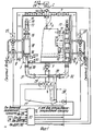
На фиг. 1 представлена структурная схема установки для химической обработки деталей на подвесках, вид с торцовой стороны ванны, разрез; на фиг. 2 представлен вид А на фиг. 1. In FIG. 1 shows a structural diagram of an installation for chemical processing of parts on suspensions, a view from the front side of the bath, a section; in FIG. 2 is a view A of FIG. 1.
Установка для химической обработки деталей на подвесках содержит ванну 1, оснащенную ловителями (на фиг. 1, 2 не обозначены) штанги 2 с подвеской 3 с деталями 4, сливным каналом 5 с ручным вентилем для регулирования расхода сливаемого раствора (на фиг. 1 не обозначен) и исполнительным механизмом (ИМ) 6 для слива последнего, двухпредельным датчиком-реле уровня обрабатывающего раствора (на фиг. 1, 2 не показан), двухстворчатой крышкой 7 с исполнительными механизмами (ИМ) для ее открывания-закрывания (на фиг. 1, 2 не показаны), бортовыми отсосами 8, 9, расположенными с обеих сторон вдоль бортов ванны 1 устройствами формирования струй обрабатывающего раствора, каждое из которых выполнено в виде горизонтально расположенных труб 10 с элементами 11 формирования струй, соединенных вертикальными патрубками 12 с полой направляющей 13 П-образной формы, оснащенной с обеих концов фланцами (на фиг. 1, 2 не обозначены), соединенной через пазы 14 в корпусе ванны 1, выполненные с элементами с изменяющейся конфигурацией, каждый из которых выполнен в виде гармошки 15 из коррозионно-влаго-термостойкого материала, с полыми штоками 16, 17 соответствующих пневмоцилиндров 18, 19 с трехходовыми электромагнитными пневматическими распределителями 20-23, используемых для возвратно-поступательного перемещения устройств формирования струй в вертикальной плоскости, ограниченной направляющими 24, расположенными в ванне 1, датчик 25 положения транспортирующего штангу 2 с подвеской 3 с деталями 4 средства (на фиг. 1, 2 не показано), датчик 26 загрузки ванны 1 подвеской 3 с деталями 4, датчики открытого и закрытого положений крышки 7 (на фиг. 1, 2 не показаны), датчики положения устройств формирования струй, емкость 27 для хранения и подготовки обрабатывающего раствора, насос 28 для подачи последнего с устройства формирования струй через коллекторы 29, 30 подвода обрабатывающего раствора, гибкие шланги 31, 32 и полые штоки 16, 17 пневмоцилиндров 18, 19, блок 33 автоматического управления процессами химической обработки и задатчик 34 вида последней. The installation for chemical processing of parts on suspensions contains a bath 1 equipped with catchers (not shown in Fig. 1, 2), a
Каждый из датчиков положения устройств формирования струй выполнен в виде передающей и воспринимающей воздействие частей, механически связанных, соответственно, с полым штоком 16 (17) соответствующего пневмоцилиндра 18 (19) и корпусом ванны 1, и выполненных в виде, соответственно, металлической пластины 35 и бесконтактного конечного выключателя 36. Each of the position sensors of the jet formation devices is made in the form of transmitting and sensing parts mechanically connected, respectively, to the hollow rod 16 (17) of the corresponding pneumatic cylinder 18 (19) and the bath body 1, and made, respectively, in the form of a
Направляющие 24 выполнены с ограничителями хода горизонтально расположенных труб с упругими элементами (на фиг. 1 не обозначены). The
Каждый из пневмоцилиндров 18, 19 выполнен с пружиной для компенсации ударных нагрузок (на фиг. 2 не обозначена). Each of the
А трехходовые электромагнитные пневматические распределители 20-23 выполнены с пневматическими дросселями для регулирования расхода сжатого воздуха (на фиг. 1 не обозначены). And the three-way electromagnetic pneumatic distributors 20-23 are made with pneumatic throttles for regulating the flow of compressed air (not shown in Fig. 1).
Поскольку работа установки аналогична прототипу, наиболее подробно рассмотрим функционирование изменяемых частей устройства. Since the operation of the installation is similar to the prototype, we will consider in more detail the functioning of the variable parts of the device.
После загрузки транспортирующим средством штанги 2 с подвеской 3 с деталями 4 в ловители ванны 1 и закрывания створок крышки 7 последней с помощью соответствующего ИМ сигналом с третьего (в данном случае) выхода блока 33 производится включение насоса 28 и подача последним обрабатывающего раствора из емкости 27, через коллекторы 29, 30, гибкие шланги 31, 32, полые штоки 16, 17 пневмоцилиндров 18, 19, полые направляющие 13 П-образной формы и вертикальные патрубки 12, в горизонтальные трубы 10, оснащенные элементами 11. After the carrier loads the
После этого сигналами с четвертого и пятого своих выходов блок 33 производит включение распределителей 21, 23, обеспечивая тем самым подачу сжатого воздуха в нижние вводы пневмоцилиндров 18, 19, для перемещения вверх их полых штоков 16, 17, соединенных с нижними их концами гибких шлангов 31, 32, устройств формирования струй и передающих воздействие частей - металлических пластин 35 датчиков положения устройств формирования струй в положение, показанное пунктиром на фиг. 1, 2. After that, with signals from its fourth and fifth outputs,
Одновременно исчезают управляющие сигналы на шестом и седьмом выходах блока 33, что приводит к отключению распределителей 20, 22 и соединению их пневмовыходов через пневмодроссели с атмосферой. At the same time, the control signals at the sixth and seventh outputs of
При этом производится перемещение вверх устройств формирования струй и струйная подача обрабатывающего раствора на детали 4. When this is done, the upward movement of the device for forming jets and the jet supply of the processing solution to the part 4 are performed.
При достижении верхнего положения устройствами формирования струй на выходах воспринимающих воздействие частей - выключателей 36 датчиков верхнего положения (ДВП) появляются сигналы, поступающие на седьмую (в данном случае) группу входов блока 33, что приводит к появлению управляющих сигналов на шестом и седьмом выходах последнего и, как следствие, включению распределителей 20, 22, обеспечивая тем самым подачу сжатого воздуха в верхние вводы пневмоцилиндров 18, 19, для перемещения вниз их полых штоков 16, 17, соединенных с нижними их концами гибких шлангов 31, 32, устройств формирования струй и передающих воздействие частей - металлических пластин 35 датчиков положения устройств формирования струй в исходное, показанное сплошной линией на фиг. 1, 2 положение. Upon reaching the upper position by the jet-forming devices, the signals arriving at the seventh (in this case) group of inputs of
Одновременно исчезают управляющие сигналы на четвертом и пятом выходах блока 33, что приводит к отключению распределителей 21, 23 и соединению их пневмоцилиндров через пневмодроссели с атмосферой. At the same time, the control signals at the fourth and fifth outputs of
В этом случае в отличие от предыдущего растягиваются верхние части жестко связанных с полыми направляющими 13 гармошек 15 и сжимаются нижние части последних. In this case, in contrast to the previous one, the upper parts of the
При достижении своего нижнего положения устройствами формирования струй и срабатывания воспринимающих воздействие частей - выключателей 36 датчиков нижнего положения (ДНП) устройств формирования струй процессы возвратно-поступательного перемещения направляющих 13, штоков 16, 17 пневмоцилиндров 18, 19, гибких шлангов 31, 32, горизонтально расположенных труб 10 с элементами 11 возобновляются описанным выше образом. Upon reaching its lower position by the devices for the formation of jets and operation of the receiving parts -
При этом обрабатывающий раствор после взаимодействия с поверхностью деталей 4 по сливному каналу 5, открытый ручной вентиль и нормально открытый ИМ 6 поступает в емкость 27. In this case, the processing solution after interacting with the surface of the parts 4 through the
После окончания времени, например, струйной обработки, выбранной с помощью задатчика 34, исчезает управляющий сигнал на третьем выходе блока 33, что приводит к отключению насоса 28 и прекращению подачи обрабатывающего раствора в устройства формирования струй, а при достижении последними своего нижнего (исходного, показанного сплошной линией на фиг. 1, 2) положения сигналы на шестом и седьмом выходах блока 33 остаются (например), а на его четвертом и пятом выходах уже не появляются. After the time, for example, of the blasting selected using the
После открывания створок крышки 7, выгрузки штанги 2 с подвеской 3 с деталями 4 из ванны 1 транспортирующим средством и перещения последнего к следующей по технологии ванне происходит закрывание створок крышки 7. After opening the flaps of the lid 7, unloading the
Установка готова для проведения нового процесса химической обработки деталей на подвесках. The installation is ready for a new process of chemical processing of parts on suspensions.
Таким образом предлагаемая установка, по сравнению с известной, выбранной в качестве прототипа, позволяет при тех же габаритах (что и в прототипе) ванны обрабатывать детали большего (в частности, по ширине) габарита. Thus, the proposed installation, in comparison with the known, selected as a prototype, allows for the same dimensions (as in the prototype) of the bath to process parts of a larger (in particular, width) dimension.
Кроме того предлагаемое устройство содержит меньшее количество элементиов и проще в эксплуатации и реализации, которая может быть осуществлена силами большинства из предприятий приборо- и машиностроения. In addition, the proposed device contains fewer elements and is easier to operate and implement, which can be implemented by most of the enterprises of instrumentation and engineering.
Claims (1)
Priority Applications (1)
| Application Number | Priority Date | Filing Date | Title |
|---|---|---|---|
| SU4950071 RU2013473C1 (en) | 1991-06-27 | 1991-06-27 | Apparatus for chemical treatment of parts on suspensions |
Applications Claiming Priority (1)
| Application Number | Priority Date | Filing Date | Title |
|---|---|---|---|
| SU4950071 RU2013473C1 (en) | 1991-06-27 | 1991-06-27 | Apparatus for chemical treatment of parts on suspensions |
Publications (1)
| Publication Number | Publication Date |
|---|---|
| RU2013473C1 true RU2013473C1 (en) | 1994-05-30 |
Family
ID=21581682
Family Applications (1)
| Application Number | Title | Priority Date | Filing Date |
|---|---|---|---|
| SU4950071 RU2013473C1 (en) | 1991-06-27 | 1991-06-27 | Apparatus for chemical treatment of parts on suspensions |
Country Status (1)
| Country | Link |
|---|---|
| RU (1) | RU2013473C1 (en) |
Cited By (3)
| Publication number | Priority date | Publication date | Assignee | Title |
|---|---|---|---|---|
| RU2426820C1 (en) * | 2009-12-28 | 2011-08-20 | Государственное Образовательное Учреждение Высшего Профессионального Образования "Московский Государственный Технический Университет Имени Н.Э. Баумана" | Procedure for jet chemical treatment and cleanup of surface of flat items |
| RU2580259C1 (en) * | 2014-12-01 | 2016-04-10 | Акционерное общество "Научно-производственное предприятие "Исток" имени А.И. Шокина" (АО "НПП "Исток" им. Шокина") | Apparatus for chemical purification and drying of articles |
| RU216682U1 (en) * | 2022-12-21 | 2023-02-17 | Общество с ограниченной ответственностью "Санкт-Петербургский Центр "ЭЛМА (Электроникс Менеджмент)" | ASSEMBLY FOR SUPPLYING A SOLUTION TO THE BLANK OF A PRINTED BOARD |
-
1991
- 1991-06-27 RU SU4950071 patent/RU2013473C1/en active
Cited By (3)
| Publication number | Priority date | Publication date | Assignee | Title |
|---|---|---|---|---|
| RU2426820C1 (en) * | 2009-12-28 | 2011-08-20 | Государственное Образовательное Учреждение Высшего Профессионального Образования "Московский Государственный Технический Университет Имени Н.Э. Баумана" | Procedure for jet chemical treatment and cleanup of surface of flat items |
| RU2580259C1 (en) * | 2014-12-01 | 2016-04-10 | Акционерное общество "Научно-производственное предприятие "Исток" имени А.И. Шокина" (АО "НПП "Исток" им. Шокина") | Apparatus for chemical purification and drying of articles |
| RU216682U1 (en) * | 2022-12-21 | 2023-02-17 | Общество с ограниченной ответственностью "Санкт-Петербургский Центр "ЭЛМА (Электроникс Менеджмент)" | ASSEMBLY FOR SUPPLYING A SOLUTION TO THE BLANK OF A PRINTED BOARD |
Similar Documents
| Publication | Publication Date | Title |
|---|---|---|
| US20110155257A1 (en) | Method and arrangement in a pneumatic material conveying system | |
| SE411707B (en) | DEVICE IN THE DRY CONDUCT FOR PRESSURE AIR | |
| RU2013473C1 (en) | Apparatus for chemical treatment of parts on suspensions | |
| RU2107551C1 (en) | Pneumatic jigging machine | |
| EP0340869A3 (en) | Supply device and method for press actuators, with recovery of the raising energy | |
| RU95116444A (en) | PNEUMATIC Jigging Machine | |
| GB900750A (en) | Improvements in remote controlled fluid-flow control valves | |
| RU2112580C1 (en) | Device for regeneration of filter granular media | |
| DE50003332D1 (en) | Hydraulic operating device for a convertible top unit of a vehicle | |
| RU2256549C2 (en) | Gripping head | |
| CN220738918U (en) | Inside cleaning machine of oxygen cylinder | |
| KR960000320A (en) | Internal cleaning device such as water supply pipe | |
| SU1154006A1 (en) | Articles washing plant | |
| SU1710467A1 (en) | Unit for pneumatic transportation of containers | |
| GB1258076A (en) | ||
| KR20230174668A (en) | Water return system by vaccum | |
| GB2263942A (en) | Valve control apparatus | |
| RU2024653C1 (en) | Production line for galvanochemical treatment of workpieces | |
| SU1658888A1 (en) | Device for feeding stalks into container | |
| EP1496295A2 (en) | Flow rate regulator valve, in particular for hydraulic systems | |
| GB1084581A (en) | Apparatus for controlling the intensity of the jigging pulses in jigging machines in which the pulstation chambers are disposed below the jig screen | |
| GB712748A (en) | Improvements in or relating to plant or apparatus for cleaning or otherwise treatingarticles in baths containing liquids | |
| CA1303458C (en) | Apparatus and method for flow control | |
| SU1122599A1 (en) | Control system for vacuum gripper | |
| SU1011834A2 (en) | Apparatus for removing horizontally sliding forms |