RU2199416C2 - Method for preventing oxygen contact with melt metal and apparatus for performing the same - Google Patents
Method for preventing oxygen contact with melt metal and apparatus for performing the same Download PDFInfo
- Publication number
- RU2199416C2 RU2199416C2 RU99119593/02A RU99119593A RU2199416C2 RU 2199416 C2 RU2199416 C2 RU 2199416C2 RU 99119593/02 A RU99119593/02 A RU 99119593/02A RU 99119593 A RU99119593 A RU 99119593A RU 2199416 C2 RU2199416 C2 RU 2199416C2
- Authority
- RU
- Russia
- Prior art keywords
- suction
- casting
- space
- inert gas
- walls
- Prior art date
Links
- 239000002184 metal Substances 0.000 title claims abstract description 25
- QVGXLLKOCUKJST-UHFFFAOYSA-N atomic oxygen Chemical compound [O] QVGXLLKOCUKJST-UHFFFAOYSA-N 0.000 title claims abstract description 21
- 239000001301 oxygen Substances 0.000 title claims abstract description 21
- 229910052760 oxygen Inorganic materials 0.000 title claims abstract description 21
- 238000000034 method Methods 0.000 title claims description 22
- 238000005266 casting Methods 0.000 claims abstract description 89
- 238000009749 continuous casting Methods 0.000 claims abstract description 12
- 230000000149 penetrating effect Effects 0.000 claims abstract 2
- 239000011261 inert gas Substances 0.000 claims description 27
- 229910000831 Steel Inorganic materials 0.000 claims description 3
- 230000003247 decreasing effect Effects 0.000 claims description 3
- 238000005096 rolling process Methods 0.000 claims description 3
- 239000010959 steel Substances 0.000 claims description 3
- 238000010926 purge Methods 0.000 claims description 2
- 238000007254 oxidation reaction Methods 0.000 abstract description 7
- 230000003647 oxidation Effects 0.000 abstract 2
- 230000000694 effects Effects 0.000 abstract 1
- 238000005272 metallurgy Methods 0.000 abstract 1
- 230000002265 prevention Effects 0.000 abstract 1
- 239000000126 substance Substances 0.000 abstract 1
- 239000000155 melt Substances 0.000 description 4
- 239000000843 powder Substances 0.000 description 3
- 238000007789 sealing Methods 0.000 description 3
- 238000001816 cooling Methods 0.000 description 2
- 238000009434 installation Methods 0.000 description 2
- 229910044991 metal oxide Inorganic materials 0.000 description 2
- 150000004706 metal oxides Chemical class 0.000 description 2
- 230000035515 penetration Effects 0.000 description 2
- 230000005855 radiation Effects 0.000 description 2
- 230000002730 additional effect Effects 0.000 description 1
- 230000015572 biosynthetic process Effects 0.000 description 1
- 238000007664 blowing Methods 0.000 description 1
- 230000007423 decrease Effects 0.000 description 1
- 230000007547 defect Effects 0.000 description 1
- 238000009826 distribution Methods 0.000 description 1
- 238000002844 melting Methods 0.000 description 1
- 230000008018 melting Effects 0.000 description 1
- 230000002093 peripheral effect Effects 0.000 description 1
- 238000010405 reoxidation reaction Methods 0.000 description 1
Images
Classifications
-
- B—PERFORMING OPERATIONS; TRANSPORTING
- B22—CASTING; POWDER METALLURGY
- B22D—CASTING OF METALS; CASTING OF OTHER SUBSTANCES BY THE SAME PROCESSES OR DEVICES
- B22D11/00—Continuous casting of metals, i.e. casting in indefinite lengths
- B22D11/06—Continuous casting of metals, i.e. casting in indefinite lengths into moulds with travelling walls, e.g. with rolls, plates, belts, caterpillars
- B22D11/0622—Continuous casting of metals, i.e. casting in indefinite lengths into moulds with travelling walls, e.g. with rolls, plates, belts, caterpillars formed by two casting wheels
-
- B—PERFORMING OPERATIONS; TRANSPORTING
- B22—CASTING; POWDER METALLURGY
- B22D—CASTING OF METALS; CASTING OF OTHER SUBSTANCES BY THE SAME PROCESSES OR DEVICES
- B22D11/00—Continuous casting of metals, i.e. casting in indefinite lengths
- B22D11/06—Continuous casting of metals, i.e. casting in indefinite lengths into moulds with travelling walls, e.g. with rolls, plates, belts, caterpillars
- B22D11/0637—Accessories therefor
- B22D11/0697—Accessories therefor for casting in a protected atmosphere
-
- B—PERFORMING OPERATIONS; TRANSPORTING
- B22—CASTING; POWDER METALLURGY
- B22D—CASTING OF METALS; CASTING OF OTHER SUBSTANCES BY THE SAME PROCESSES OR DEVICES
- B22D11/00—Continuous casting of metals, i.e. casting in indefinite lengths
- B22D11/06—Continuous casting of metals, i.e. casting in indefinite lengths into moulds with travelling walls, e.g. with rolls, plates, belts, caterpillars
- B22D11/0637—Accessories therefor
- B22D11/064—Accessories therefor for supplying molten metal
- B22D11/0642—Nozzles
-
- B—PERFORMING OPERATIONS; TRANSPORTING
- B22—CASTING; POWDER METALLURGY
- B22D—CASTING OF METALS; CASTING OF OTHER SUBSTANCES BY THE SAME PROCESSES OR DEVICES
- B22D11/00—Continuous casting of metals, i.e. casting in indefinite lengths
- B22D11/12—Accessories for subsequent treating or working cast stock in situ
-
- B—PERFORMING OPERATIONS; TRANSPORTING
- B22—CASTING; POWDER METALLURGY
- B22D—CASTING OF METALS; CASTING OF OTHER SUBSTANCES BY THE SAME PROCESSES OR DEVICES
- B22D27/00—Treating the metal in the mould while it is molten or ductile ; Pressure or vacuum casting
- B22D27/003—Treating the metal in the mould while it is molten or ductile ; Pressure or vacuum casting by using inert gases
Landscapes
- Engineering & Computer Science (AREA)
- Mechanical Engineering (AREA)
- Continuous Casting (AREA)
- Manufacture And Refinement Of Metals (AREA)
- Waste-Gas Treatment And Other Accessory Devices For Furnaces (AREA)
- Coupling Device And Connection With Printed Circuit (AREA)
- Manufacture Of Switches (AREA)
- Investigating Or Analyzing Non-Biological Materials By The Use Of Chemical Means (AREA)
- Investigating Or Analysing Materials By The Use Of Chemical Reactions (AREA)
- Spark Plugs (AREA)
Abstract
Description
Изобретение относится к способу предотвращения контакта кислорода с металлическим расплавом при непрерывной разливке, причем металлический расплав затекает в ограниченное стенками разливочное пространство и выходит из него в виде отливки, а также к устройству для осуществления способа. The invention relates to a method for preventing oxygen from contacting a metal melt during continuous casting, the metal melt flowing into and out of the bounded space bounded by the walls and also to a device for implementing the method.
При непрерывной разливке в разливочном пространстве происходит скопление металлического расплава, который необходимо предохранить от повторного окисления, а зеркало его ванны - от сильной теплоотдачи в результате излучения. При традиционной непрерывной разливке зеркало ванны покрывают для этой цели литейным порошком или маслом. During continuous casting, a metal melt accumulates in the pouring space, which must be protected from re-oxidation, and the mirror of its bath from strong heat transfer as a result of radiation. In conventional continuous casting, the bathtub mirror is coated with casting powder or oil for this purpose.
Для литья тонких лент известны различные способы, в которых разливочное пространство образовано не неподвижными стенками, а одной движущейся вместе с отливкой стенкой или несколькими движущимися вместе с отливкой стенками, например гусеничной лентой согласно европейской заявке 0526886, или валком согласно европейской заявке 0568211 или европейскому патенту 0040072, или двумя движущимися навстречу друг другу разливочными валками согласно заявке США 4987949 или европейскому патенту 0430841. При осуществлении этих способов невозможно надежно защитить металлический расплав литейным порошком или маслом от повторного окисления или теплоотдачи, как это в большинстве случаев происходит в разливочных пространствах или кристаллизаторах с неподвижными стенками. Various methods are known for casting thin tapes, in which the casting space is formed not by fixed walls, but by one wall moving along with the casting or several walls moving together with the casting, for example, a caterpillar tape according to European application 0526886, or a roller according to European application 0568211 or European patent 0040072 , or two casting rolls moving towards each other according to US application 4987949 or European patent 0430841. When implementing these methods, it is impossible to reliably protect m metal melt by casting powder or oil from re-oxidation or heat transfer, as in most cases occurs in casting spaces or molds with fixed walls.
Из европейского патента 0430841 у двухвалковой разливочной установки известна защита зеркала ванны кожухом от сильной теплоотдачи в результате излучения и от повторного окисления. У этого решения, однако, оказалось, что на поверхностях контакта между кожухом и разливочными валками как у кожуха, так и у разливочных валков, возникает сильный износ и из-за тепловой деформации деталей невозможно предотвратить проникновение воздуха и, тем самым, кислорода через щели между ограничивающими разливочное пространство стенками. Происходит повторное окисление расплава со всеми вытекающими отсюда последствиями. From European patent 0430841 for a two-roll casting installation, it is known to protect a bath mirror by a casing against strong heat transfer as a result of radiation and from re-oxidation. This solution, however, turned out that on the contact surfaces between the casing and the casting rolls, both the casing and the casting rolls, severe wear occurs and due to thermal deformation of the parts, it is impossible to prevent the penetration of air and, therefore, oxygen through the cracks between walls bounding the filling space. The reoxidation of the melt occurs with all the ensuing consequences.
Для уменьшения проникновения воздуха через щель между кожухом и разливочными валками в заявке США 4987949 и в европейской заявке 0714716 предложено вдувание в определенную щель между кожухом и разливочными валками инертного газа, преимущественно азота или аргона, и возведение, таким образом, барьера против проникновения воздуха. Этой меры, однако, не достаточно для полного предотвращения проникновения воздуха в разливочное пространство и, тем самым, к зеркалу ванны, так что, с одной стороны, по-прежнему на поверхности ванны образуются оксиды металла, приводящие к дефектам внутри металлической ленты. С другой стороны, на поверхности образующейся оболочки отливки образуются оксиды металла или же кислород диффундирует в краевой слой металлической ленты и образует там включения, что повышает склонность к трещинообразованию. Несмотря на подачу инертного газа в так называемом ламинарном нижнем слое пограничного слоя потока застрявший в микрошероховатостях поверхности валков воздух заносится в разливочное пространство. Этот нижний слой застревает в микрошероховатостях поверхности валков, и его невозможно удалить ни контактными скользящими уплотнениями, ни бесконтактными уплотнениями. In order to reduce the penetration of air through the gap between the casing and the casting rolls, U.S. Pat. This measure, however, is not sufficient to completely prevent air from entering the pouring space and, thus, to the bathtub mirror, so that, on the one hand, metal oxides are still formed on the bathtub surface, leading to defects inside the metal strip. On the other hand, metal oxides are formed on the surface of the formed casting shell or oxygen diffuses into the edge layer of the metal tape and forms inclusions there, which increases the tendency to crack formation. Despite the inert gas supply in the so-called laminar lower layer of the boundary layer of the flow, air stuck in the microroughnesses of the surface of the rolls is brought into the filling space. This lower layer is stuck in the microroughnesses of the surface of the rolls and cannot be removed by either sliding contact seals or non-contact seals.
Изобретение ставит своей целью устранение этих недостатков и трудностей, а своей задачей - создание способа описанного выше рода, а также устройства для непрерывной разливки, с помощью которого можно предотвратить контакт кислорода с металлическим расплавом и которое полностью предотвращает повторное окисление, а именно даже тогда, когда возникает сильный износ в щелях, имеющихся между образующими разливочное пространство стенками. В частности, должно быть возможным удаление также так называемого ламинарного нижнего слоя, а именно приставшего к образующим разливочное пространство стенкам или привнесенного воздушного слоя. The invention aims to eliminate these drawbacks and difficulties, and its task is to create a method of the kind described above, as well as a device for continuous casting, with which you can prevent contact of oxygen with a metal melt and which completely prevents re-oxidation, namely even when severe wear occurs in the gaps between the walls forming the casting space. In particular, it should also be possible to remove the so-called laminar lower layer, namely the adhering to the walls forming the filling space or the introduced air layer.
Эта задача решается в способе описанного выше рода за счет того, что стремящийся проникнуть через возможные щели между стенками и/или приставший к стенкам кислород отсасывают. This problem is solved in a method of the kind described above due to the fact that aspirant is sucked out by trying to penetrate through possible gaps between the walls and / or the oxygen adhering to the walls.
Особенно эффективное удаление кислорода достигается предпочтительно за счет того, что отсос осуществляют в несколько ступеней, расположенных друг за другом снаружи внутрь в направлении разливочного пространства, причем целесообразно отсос осуществляют с давлением, уменьшающимся от ступени к ступени снаружи внутрь в направлении разливочного пространства. A particularly effective removal of oxygen is preferably achieved due to the fact that the suction is carried out in several stages, one after the other from the outside inward in the direction of the pouring space, moreover, it is advisable to carry out the suction with pressure decreasing from the step to the step from the outside inward in the direction of the pouring space.
При этом согласно предпочтительной форме выполнения давление отсоса на ближайшей к разливочному пространству ступени устанавливают ниже 50 мбар, преимущественно ниже 10 мбар. Moreover, according to a preferred embodiment, the suction pressure at the stage closest to the pouring space is set below 50 mbar, preferably below 10 mbar.
Для обеспечения выравнивания давления относительно разливочного пространства целесообразно непосредственно по соседству с ближайшей к разливочному пространству зоной отсоса по ограничивающей разливочное пространство стенке к ней подают инертный газ, причем предпочтительно давление инертного газа, по меньшей мере, на 10 мбар, преимущественно более чем на 200 мбар, выше давления соседней ступени отсоса. In order to ensure equalization of pressure with respect to the pouring space, it is expedient to use inert gas directly to the suction zone adjacent to the pouring space along the wall bounding the pouring space, moreover, the pressure of the inert gas is preferably at least 10 mbar, preferably more than 200 mbar, higher than the pressure of the adjacent suction stage.
Преимущественно инертный газ вдувают к стенке в несколько ступеней, расположенных снаружи внутрь в направлении разливочного пространства. A predominantly inert gas is blown into the wall in several stages, located from the outside inward in the direction of the filling space.
Целесообразно инертный газ вдувают на стенку со скоростью, по меньшей мере, 0,5 м/с, максимально 10 м/с, преимущественно более 2 м/с. An inert gas is expediently blown onto the wall at a speed of at least 0.5 m / s, maximum 10 m / s, preferably more than 2 m / s.
В способе разливки, в котором, по меньшей мере, одну стенку перемещают относительно разливочного пространства, согласно предпочтительной форме выполнения, заново входящие в разливочное пространство участки этой стенки перед вхождением освобождают от приставшего к ним кислорода путем отсоса кислорода. Непрерывную разливку осуществляют тогда предпочтительно валковым способом, преимущественно двухвалковым способом, т.е. для способа согласно изобретению пригодны также способы только с одним разливочным валком, как это описано, например в европейском патенте 0040072. Само собой, способ согласно изобретению можно применять также при литье металлического расплава на произвольном подвижном охлаждающем теле, например гусеничной ленте согласно заявке ФРГ 3602594. При определенных обстоятельствах это предпочтительно также для кристаллизаторов с неподвижными стенками, например когда нанесение литейного порошка было бы невозможным или слишком сложным делом. In a casting method in which at least one wall is moved relative to the casting space, according to a preferred embodiment, portions of this wall re-entering the casting space are released from the oxygen adhering to them by the suction of oxygen before entering. Continuous casting is then preferably carried out by a roll method, preferably a two-roll method, i.e. methods with only one casting roll are also suitable for the method according to the invention, as described, for example, in European patent 0040072. Of course, the method according to the invention can also be applied when casting metal melt on an arbitrary movable cooling body, for example a caterpillar track according to the application of Germany 3602594. Under certain circumstances, this is also preferable for molds with fixed walls, for example, when the application of casting powder would be impossible or too complicated.
Устройство, с помощью которого можно предотвратить контакт кислорода с металлическим расплавом при непрерывной разливке, причем ограниченное стенками разливочное пространство заполнено металлическим расплавом и из разливочного пространства через его разливочную щель выходит отливка, отличается тем, что на возможных имеющихся между соседними стенками щелях предусмотрено отсасывающее устройство для стремящегося проникнуть через щели и/или приставшего к стенкам кислорода. A device with which oxygen can be prevented from contacting the metal melt during continuous casting, the casting space limited by the walls being filled with the metal melt and the casting leaving the casting space through its casting slot, is characterized in that a suction device is provided for possible slots between adjacent walls seeking to penetrate through cracks and / or adhering to the walls of oxygen.
В устройстве для непрерывного литья металлической ленты, преимущественно стальной ленты, содержащего два вращающихся навстречу друг другу разливочных валка с расположенными рядом параллельно друг другу осями и двумя боковыми щитками, образующими сообща разливочное пространство для приема жидкого металла, кожух, который расположен над разливочным пространством и закрывает его вверх, а также отсасывающее устройство, которое предотвращает доступ воздуха в разливочное пространство вдоль щели, образованной кожухом и вращающимися разливочными валками, лежащая в основе изобретения задача решается предпочтительно за счет того, что отсасывающее устройство образовано, по меньшей мере, одной отсасывающей камерой, расположенной со стороны атмосферы вблизи щели между вращающимися разливочными валками и кожухом и простирающейся параллельно оси валка. In a device for continuous casting of a metal strip, mainly a steel strip, containing two casting rolls rotating towards each other with axes located adjacent to each other and two side shields forming a casting space for receiving molten metal, a casing that is located above the casting space and closes upward, as well as a suction device that prevents air from entering the pouring space along the gap formed by the casing and the rotating spill face-to-face rolls, the underlying problem is preferably achieved by the fact that the suction device is formed by at least one suction chamber located on the side of the atmosphere near the gap between the rotating casting rolls and the casing and extending parallel to the roll axis.
Особенно эффективно это отсасывающее устройство действует тогда, когда оно образовано несколькими отсасывающими камерами, расположенными рядом в направлении периферии разливочных валков. При этом предпочтительно, если каждая отсасывающая камера через отсасывающий трубопровод соединена с соответствующим отсасывающим насосом или ступенью многоступенчатого отсасывающего насоса. Согласно конструктивно простой форме выполнения отсасывающее устройство выполнено в виде последовательной многокамерной системы. Благодаря этой мере давление всасывания уменьшается в направлении движения разливочных валков от одной отсасывающей камеры к другой. За счет соответствующего согласования числа отсасывающих камер с окружной скоростью разливочных валков достигается полное удаление привнесенного воздуха. This suction device is particularly effective when it is formed by several suction chambers located adjacent to the periphery of the casting rolls. In this case, it is preferable if each suction chamber is connected through a suction pipe to a corresponding suction pump or a stage of a multi-stage suction pump. According to a structurally simple form of execution, the suction device is made in the form of a sequential multi-chamber system. Due to this measure, the suction pressure decreases in the direction of movement of the casting rolls from one suction chamber to another. Due to the appropriate coordination of the number of suction chambers with the peripheral speed of the casting rolls, complete removal of introduced air is achieved.
Согласно усовершенствованной форме выполнения уплотнительное устройство расположено на определенном расстоянии от поверхности разливочных валков, и щель, образованная уплотнительным устройством и поверхностью разливочных валков, по меньшей мере, со стороны входа и выхода уплотнена контактными уплотнениями, преимущественно щеточными или резиновыми манжетными уплотнениями. За счет этого доступ воздуха уже перед первой отсасывающей камерой в значительной степени ограничен воздухом, привнесенным с пограничным слоем. According to an improved embodiment, the sealing device is located at a certain distance from the surface of the casting rolls, and the gap formed by the sealing device and the surface of the casting rolls is sealed at least from the inlet and outlet side by contact seals, mainly brush or rubber lip seals. Due to this, the air access already in front of the first suction chamber is largely limited by the air introduced from the boundary layer.
Согласно другой форме выполнения, по меньшей мере, одна их отсасывающих камер дополнительно оснащена продувкой инертным газом. According to another embodiment, at least one of the suction chambers is further equipped with an inert gas purge.
Устройство усовершенствовано за счет того, что между кожухом и отсасывающим устройством расположен подвод для инертного газа, причем этот подвод для инертного газа выполнен в виде вакуумной камеры с направленным к разливочным валкам отверстием. Предпочтительно отверстие выполнено в виде сопла, которое направлено наискось к поверхности разливочных валков и наклонено к соседней отсасывающей камере. Благодаря этой мере на разливочный валок наносится близкий к нему слой инертного газа, и таким образом создается прекрасная защита от доступа кислорода или воздуха. При нанесении на разливочный валок слоя инертного газа толщиной несколько миллиметров и при использовании инертного газа тяжелее воздуха необязательно, чтобы кожух примыкал непосредственно к подводу для инертного газа и к отсасывающему устройству. The device is improved due to the fact that between the casing and the suction device there is an inert gas supply, and this inert gas supply is made in the form of a vacuum chamber with an opening directed to the casting rolls. Preferably, the hole is made in the form of a nozzle, which is directed obliquely to the surface of the casting rolls and inclined to an adjacent suction chamber. Due to this measure, a layer of inert gas close to it is applied to the casting roll, and thus creates excellent protection against access of oxygen or air. When applying a layer of inert gas several millimeters thick on the casting roll and using inert gas heavier than air, it is not necessary that the casing adjoins directly to the inert gas supply and to the suction device.
Другие признаки и преимущества вытекают из нижеследующего описания устройства и способа литья металлической ленты в нескольких формах выполнения. Other features and advantages arise from the following description of the device and method of casting a metal strip in several forms.
На фиг.1 изображено сечение двухвалковой разливочной установки с уплотнительным устройством согласно изобретению в первой форме выполнения. Figure 1 shows a cross-section of a twin-roll filling machine with a sealing device according to the invention in a first embodiment.
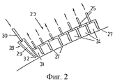
На фиг.2 изображена вторая форма выполнения отсасывающего устройства согласно изобретению. Figure 2 shows a second embodiment of a suction device according to the invention.
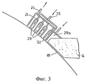
На фиг.3 изображена третья форма выполнения отсасывающего устройства согласно изобретению. Figure 3 shows a third embodiment of a suction device according to the invention.
Двухвалковая разливочная установка, изображенная на фиг.1 схематично в разрезе, содержит два приводимых разливочных валка 1, 2, расположенные параллельно друг другу, оси 3, 4 которых лежат в одной горизонтальной плоскости. Оба вращающихся навстречу друг другу по стрелкам 5, 6 разливочных валка 1, 2 снабжены внутренним охлаждением (не показано) для их рубашки, образующей поверхность 7 разливочных валков. Разливочные валки 1, 2 и боковые щитки 8 образуют разливочное пространство 9, в которое из плавильного резервуара или распределительного сосуда (не показан) через снабженное выходными отверстиями 11 подающее сопло 10 подают расплав 20. Разливочное пространство 9 ограничено вверх от разливочных валков 1, 2 и боковых щитков кожухом 13, имеющим со стороны расплава огнеупорную облицовку 14 для защиты расплава 20 от слишком больших тепловых потерь и от повторного окисления кислородом воздуха. С помощью несущего устройства 15 для кожуха 13, юстируемого регулировочными элементами 17 относительно неподвижной станины 16, устанавливают нужную минимальную щель 18 между кожухом 13 и разливочными валками 1, 2. Через кожух 13 проходит подающее сопло 10, причем между этими обеими деталями предусмотрена, по возможности, небольшая щель, закрываемая при необходимости уплотнением. The two-roll casting plant shown in Fig. 1 schematically in section, contains two driven casting rolls 1, 2 located parallel to each other, axes 3, 4 of which lie in the same horizontal plane. Both rotating towards each other along the arrows 5, 6 of the casting roll 1, 2 are equipped with internal cooling (not shown) for their shirt, forming the surface 7 of the casting rolls. The casting rolls 1, 2 and side flaps 8 form a casting space 9 into which a melt 20 is supplied from the melting tank or distribution vessel (not shown) through the supply nozzle 10 and the casting space 9 is bounded upward from the casting rolls 1, 2 and side shields with a casing 13 having a
С помощью двухвалковой разливочной установки такой конфигурации можно отливать тонкую металлическую ленту, в частности стальную ленту, толщиной от 1 до 12 мм, причем разливаемый расплав 20, как описано выше, непрерывно заполняет разливочное пространство 9. На вращающихся навстречу друг другу и охлаждаемых разливочных валках 1, 2 образуются становящиеся все более толстыми оболочки отливки, которые в самом узком сечении между разливочными валками соединяются в отформованную разливочными валками ленту. Толщина выдаваемой разливочными валками ленты определяется расстоянием между обоими разливочными валками. Using a twin-roll casting installation of this configuration, it is possible to cast a thin metal strip, in particular a steel strip, from 1 to 12 mm thick, and the molten melt 20, as described above, continuously fills the casting space 9. On rotating and cooled casting rolls 1 2, casting shells are becoming increasingly thicker, which in the narrowest section between the casting rolls are connected into a tape formed by the casting rolls. The thickness of the tape dispensed by the casting rolls is determined by the distance between the two casting rolls.
Для предотвращения доступа воздуха в разливочное пространство 9 вдоль щелей 18, образованных кожухом 13 и вращающимися разливочными валками 1, 2, образованное отсасывающей камерой 24 отсасывающее устройство 23 расположено со стороны атмосферы вблизи щели 18 и на небольшом расстоянии от поверхности 7 разливочных валков. Отсасывающая камера 24 открыта к поверхности 7 разливочных валков и соединена с отсасывающим трубопроводом 25, а также отсасывающим насосом (на чертеже не показан). Отсасывающая камера 24 образована просто открытым к поверхности разливочных валков U-образным профилем, который проходит параллельно оси 3, 4 валка на небольшом расстоянии от поверхности разливочных валков по всей их длине. Щель между отсасывающей камерой 24 и поверхностью 7 разливочных валков закрыта закрепленными на полках U-образного профиля и касающимися поверхности 7 разливочных валков уплотнениями 27, которые выполнены преимущественно в виде щеточных или резиновых манжетных уплотнений. To prevent air from entering the pouring space 9 along the
Согласно другой форме выполнения, изображенной на фиг.2, отсасывающее устройство 23 образовано несколькими расположенными рядом в направлении периферии разливочных валков 1, 2 отсасывающими камерами 24, и каждая отсасывающая камера через соответствующий всасывающий трубопровод 25 соединена с одной ступенью многоступенчатого отсасывающего насоса (не показан). Это отсасывающее устройство 23, выполненное в виде последовательной многокамерной системы, позволяет удалять привнесенный воздух в несколько ступеней отсоса со ступенчато уменьшающимся в направлении вращения разливочных валков давлением в камерах. Давление в последней в направлении вращения разливочных валков отсасывающей камере 31 установлено для достижения оптимального отсоса воздуха на значение ниже 50 мбар, преимущественно ниже 10 мбар. According to another embodiment shown in FIG. 2, the
В форме выполнения по фиг.1 между отсасывающей камерой 24 и кожухом 13 дополнительно расположен подвод 28 для инертного газа, который образован вакуумной камерой 29 и имеет направленное к поверхности разливочных валков отверстие 32. Дополнительно оно соединено с подающим трубопроводом 30 для инертного газа. Детально вакуумная камера 29 выполнена аналогично отсасывающей камере 24, и во избежание доступа побочного воздуха обе объединены в один узел. По той же причине вакуумная камера 29 также герметично соединена с кожухом 13. In the embodiment of FIG. 1, an
В форме выполнения, изображенной на фиг.2, вакуумная камера 29 выполнена с направленным к поверхности 7 разливочных валков выходным отверстием, причем вакуумная камера объединена с последовательной многокамерной системой отсасывающего устройства 23 в один узел и герметизирована от доступа воздуха. In the embodiment shown in FIG. 2, the
Инертный газ подают в вакуумную камеру 29, с тем чтобы создать на поверхности 7 разливочных валков пограничный слой потока инертного газа, вводимый через щель 18 между разливочными валками 1,2 и кожухом 13 вместо воздуха в разливочное пространство 9. Для этого достаточно установить в вакуумной камере 29 давление, по меньшей мере, на 10 мбар, преимущественно более чем на 200 мбар выше давления расположенного перед ней отсасывающего устройства 23. Inert gas is supplied to the
На фиг. 3 изображена форма выполнения, у которой внутри соединенной с отсасывающим трубопроводом 25 отсасывающей камеры 24 для отсоса побочного воздуха расположено несколько вакуумных камер 29, соединенных с одним общим подводом 28 для инертного газа. В последней в направлении вращения разливочных валков и расположенной непосредственно перед кожухом 13 вакуумной камере 29а в противоположность предшествующим вакуумным камерам 29 давление инертного газа устанавливают на значение выше атмосферного давления. In FIG. 3 shows an embodiment in which
Последние остатки кислорода воздуха, приставшего в пограничном слое к поверхности 7 разливочных валков, могут быть удалены с помощью продувки инертным газом, если инертный газ вдувают к поверхности 7 разливочных валков, для чего скорость набегающего потока устанавливают, по меньшей мере, 0,5 м/с, преимущественно более 2 м/с. Скорости набегающего потока более 10 м/с не дают никакого дополнительного эффекта. The last residual oxygen of the air adhering to the surface 7 of the casting rolls in the boundary layer can be removed by blowing with an inert gas if the inert gas is blown to the surface 7 of the casting rolls, for which the flow velocity is set to at least 0.5 m / s, mainly more than 2 m / s. Free flow speeds of more than 10 m / s do not give any additional effect.
Claims (21)
Applications Claiming Priority (2)
| Application Number | Priority Date | Filing Date | Title |
|---|---|---|---|
| ITRM97A000082 | 1997-02-14 | ||
| IT97RM000082A IT1290932B1 (en) | 1997-02-14 | 1997-02-14 | PROCEDURE AND DEVICE FOR PREVENTING OXYGEN CONTACT WITH A MOLTEN METAL MASS. |
Publications (2)
| Publication Number | Publication Date |
|---|---|
| RU99119593A RU99119593A (en) | 2001-08-20 |
| RU2199416C2 true RU2199416C2 (en) | 2003-02-27 |
Family
ID=11404759
Family Applications (1)
| Application Number | Title | Priority Date | Filing Date |
|---|---|---|---|
| RU99119593/02A RU2199416C2 (en) | 1997-02-14 | 1998-02-12 | Method for preventing oxygen contact with melt metal and apparatus for performing the same |
Country Status (17)
| Country | Link |
|---|---|
| US (1) | US6415849B1 (en) |
| EP (1) | EP0961665B1 (en) |
| JP (1) | JP2001512371A (en) |
| KR (1) | KR100525035B1 (en) |
| CN (1) | CN1072056C (en) |
| AT (1) | ATE202304T1 (en) |
| AU (1) | AU744243B2 (en) |
| BR (1) | BR9807225A (en) |
| CA (1) | CA2281703A1 (en) |
| DE (1) | DE59800886D1 (en) |
| ES (1) | ES2160406T3 (en) |
| ID (1) | ID22429A (en) |
| IT (1) | IT1290932B1 (en) |
| PL (1) | PL335252A1 (en) |
| RU (1) | RU2199416C2 (en) |
| UA (1) | UA48296C2 (en) |
| WO (1) | WO1998035773A1 (en) |
Cited By (1)
| Publication number | Priority date | Publication date | Assignee | Title |
|---|---|---|---|---|
| RU2343039C2 (en) * | 2003-05-19 | 2009-01-10 | Фоест-Альпине Индустрианлагенбау Гмбх Унд Ко. | Manufacturing tecnhique of cast metal strip and two-rolls casting plant for it |
Families Citing this family (4)
| Publication number | Priority date | Publication date | Assignee | Title |
|---|---|---|---|---|
| JP2002113555A (en) * | 2000-10-10 | 2002-04-16 | Castrip Llc | Twin-roll type continuous caster and its using method |
| CN103451371B (en) * | 2013-09-10 | 2016-01-20 | 泰州鑫宇精密铸造有限公司 | Induction furnace molten steel covers blowing argon pouring technology and device |
| AT520033B1 (en) | 2017-06-02 | 2022-01-15 | Asmag Holding Gmbh | extrusion machine |
| CN113231610B (en) * | 2021-04-30 | 2022-09-23 | 中冶赛迪工程技术股份有限公司 | Arc vibration thin strip continuous casting method and thin strip continuous casting and rolling production line |
Citations (3)
| Publication number | Priority date | Publication date | Assignee | Title |
|---|---|---|---|---|
| SU946791A1 (en) * | 1981-02-25 | 1982-07-30 | Всесоюзный научно-исследовательский и проектный институт титана | Apparatus for continuous casting of readily oxidizable metals and alloys |
| US4987949A (en) * | 1988-07-29 | 1991-01-29 | Hitachi Zosen Corporation | Protective cover for surface of molten steel used in continuous casting apparatus |
| RU2025198C1 (en) * | 1991-12-05 | 1994-12-30 | Юзинор Сасилор С.А. | Method and device for manufacturing strip from semiferritic stainless steel |
Family Cites Families (14)
| Publication number | Priority date | Publication date | Assignee | Title |
|---|---|---|---|---|
| US3920062A (en) * | 1972-10-03 | 1975-11-18 | Special Metals Corp | Control method for continuously casting liquid metal produced from consumable electrodes |
| DE2747061A1 (en) | 1977-10-20 | 1979-04-26 | Leybold Heraeus Gmbh & Co Kg | Vacuum chamber for coating strip - has air lock chambers to permit continuous coating |
| DE2831710B1 (en) * | 1978-07-19 | 1979-10-25 | Messerschmitt Boelkow Blohm | Device for increasing the vacuum in a vacuum chamber through which a belt passes |
| DE2950406C2 (en) * | 1979-12-14 | 1986-12-04 | Hitachi Metals, Ltd., Tokyo | Device for the continuous casting of a metal strip |
| YU43229B (en) * | 1980-05-09 | 1989-06-30 | Battelle Development Corp | Device for continuous band casting |
| JPS6040653A (en) * | 1983-08-12 | 1985-03-04 | Hitachi Ltd | Vacuum melting continuous casting method |
| DE3602594A1 (en) | 1986-01-29 | 1987-07-30 | Sundwiger Eisen Maschinen | Apparatus for casting metal strips on a moving cooling element |
| FR2654657B1 (en) | 1989-11-22 | 1992-03-20 | Siderurgie Fse Inst Rech | DEVICE FOR CONTINUOUS CASTING OF THIN STRIPS OF METAL BETWEEN TWO CYLINDERS. |
| SE507606C2 (en) | 1991-03-06 | 1998-06-29 | Tetra Laval Holdings & Finance | Apparatus for making web-shaped metal foil |
| AU1955592A (en) * | 1991-08-06 | 1993-02-11 | Olin Corporation | Casting of metal strip |
| JP3172187B2 (en) * | 1992-04-24 | 2001-06-04 | 石川島播磨重工業株式会社 | Continuous strip casting method and apparatus |
| US5293926A (en) | 1992-04-30 | 1994-03-15 | Allegheny Ludlum Corporation | Method and apparatus for direct casting of continuous metal strip |
| FR2727338A1 (en) * | 1994-11-30 | 1996-05-31 | Usinor Sacilor | CONTINUOUS CASTING DEVICE BETWEEN INHERENT COVER CYLINDERS |
| US5535812A (en) * | 1995-01-06 | 1996-07-16 | Singleton Technology, Inc. | Method of and apparatus for continuous casting of metal |
-
1997
- 1997-02-14 IT IT97RM000082A patent/IT1290932B1/en active IP Right Grant
-
1998
- 1998-02-12 PL PL98335252A patent/PL335252A1/en unknown
- 1998-02-12 WO PCT/EP1998/000788 patent/WO1998035773A1/en not_active Ceased
- 1998-02-12 RU RU99119593/02A patent/RU2199416C2/en not_active IP Right Cessation
- 1998-02-12 US US09/367,434 patent/US6415849B1/en not_active Expired - Fee Related
- 1998-02-12 DE DE59800886T patent/DE59800886D1/en not_active Expired - Fee Related
- 1998-02-12 JP JP53534498A patent/JP2001512371A/en active Pending
- 1998-02-12 ES ES98910649T patent/ES2160406T3/en not_active Expired - Lifetime
- 1998-02-12 EP EP98910649A patent/EP0961665B1/en not_active Expired - Lifetime
- 1998-02-12 ID IDW990629A patent/ID22429A/en unknown
- 1998-02-12 CN CN98802525A patent/CN1072056C/en not_active Expired - Fee Related
- 1998-02-12 AU AU64963/98A patent/AU744243B2/en not_active Ceased
- 1998-02-12 AT AT98910649T patent/ATE202304T1/en not_active IP Right Cessation
- 1998-02-12 BR BR9807225-0A patent/BR9807225A/en not_active IP Right Cessation
- 1998-02-12 KR KR10-1999-7006578A patent/KR100525035B1/en not_active Expired - Fee Related
- 1998-02-12 CA CA002281703A patent/CA2281703A1/en not_active Abandoned
- 1998-12-02 UA UA99084539A patent/UA48296C2/en unknown
Patent Citations (3)
| Publication number | Priority date | Publication date | Assignee | Title |
|---|---|---|---|---|
| SU946791A1 (en) * | 1981-02-25 | 1982-07-30 | Всесоюзный научно-исследовательский и проектный институт титана | Apparatus for continuous casting of readily oxidizable metals and alloys |
| US4987949A (en) * | 1988-07-29 | 1991-01-29 | Hitachi Zosen Corporation | Protective cover for surface of molten steel used in continuous casting apparatus |
| RU2025198C1 (en) * | 1991-12-05 | 1994-12-30 | Юзинор Сасилор С.А. | Method and device for manufacturing strip from semiferritic stainless steel |
Cited By (1)
| Publication number | Priority date | Publication date | Assignee | Title |
|---|---|---|---|---|
| RU2343039C2 (en) * | 2003-05-19 | 2009-01-10 | Фоест-Альпине Индустрианлагенбау Гмбх Унд Ко. | Manufacturing tecnhique of cast metal strip and two-rolls casting plant for it |
Also Published As
| Publication number | Publication date |
|---|---|
| ITRM970082A1 (en) | 1998-08-14 |
| UA48296C2 (en) | 2002-08-15 |
| ATE202304T1 (en) | 2001-07-15 |
| EP0961665B1 (en) | 2001-06-20 |
| US6415849B1 (en) | 2002-07-09 |
| WO1998035773A1 (en) | 1998-08-20 |
| AU6496398A (en) | 1998-09-08 |
| CN1072056C (en) | 2001-10-03 |
| ES2160406T3 (en) | 2001-11-01 |
| KR20000070345A (en) | 2000-11-25 |
| CA2281703A1 (en) | 1998-08-20 |
| PL335252A1 (en) | 2000-04-10 |
| EP0961665A1 (en) | 1999-12-08 |
| CN1247488A (en) | 2000-03-15 |
| ID22429A (en) | 1999-10-14 |
| AU744243B2 (en) | 2002-02-21 |
| DE59800886D1 (en) | 2001-07-26 |
| BR9807225A (en) | 2000-04-25 |
| KR100525035B1 (en) | 2005-11-01 |
| JP2001512371A (en) | 2001-08-21 |
| IT1290932B1 (en) | 1998-12-14 |
Similar Documents
| Publication | Publication Date | Title |
|---|---|---|
| CA2230369C (en) | Continuous hot-dip coating method and apparatus therefor | |
| RU2199416C2 (en) | Method for preventing oxygen contact with melt metal and apparatus for performing the same | |
| EA004448B1 (en) | Method and installation for deep coating of a metal strip | |
| US4648438A (en) | Method and apparatus for feeding and continuously casting molten metal with inert gas applied to the moving mold surfaces and to the entering metal | |
| CA1208412A (en) | Methods and apparatus for feeding and continuously casting molten metal with inert gas applied to the moving mold surfaces and to the entering metal | |
| US4593742A (en) | Apparatus for feeding and continuously casting molten metal with inert gas applied to the moving mold surfaces and to the entering metal | |
| JP4373796B2 (en) | Steel strip casting | |
| CA2101217C (en) | Tundish outlet edge seal and riser for continuous casting apparatus and method | |
| CN101198421A (en) | Pinch roll device and method of operating the same | |
| MXPA99006967A (en) | How to avoid contact between oxygen and molten metal | |
| JP3983815B2 (en) | Method for preventing oxygen contact with molten metal | |
| RU99119593A (en) | METHOD AND DEVICE FOR PREVENTION OF CONTACT OF OXYGEN WITH METAL MELT | |
| NL8401742A (en) | METHOD FOR SUPPLYING A METAL MELT | |
| JPH066751B2 (en) | Cooling and sealing device | |
| JPH0776759A (en) | Aerial pot for hot metal plating | |
| EP1340565A3 (en) | Device and method for the continuous casting of a strip from a molten metal | |
| JPH03275249A (en) | Conveying device in production of rapidly cooled metal strip under inert atmosphere | |
| CA2213630A1 (en) | Continuous casting plant | |
| JP2710946B2 (en) | Continuous ribbon casting machine | |
| KR950008974Y1 (en) | Device for prevention slag mixing of sheet casting | |
| JP3083718B2 (en) | Continuous casting of thin slabs | |
| CZ9902849A3 (en) | Method of preventing contact of oxygen with molten metal and apparatus for making the same | |
| NL8401744A (en) | METHOD FOR PREVENTING THE ENTRY OF METAL BETWEEN A COQUILLE WALL AND A CASTING PIPE | |
| JPH06210413A (en) | Single belt continuous casting method |
Legal Events
| Date | Code | Title | Description |
|---|---|---|---|
| MM4A | The patent is invalid due to non-payment of fees |
Effective date: 20050213 |