RU2258024C2 - Plant for charging several consumers with loose material, for instance, loading of aluminium melting furnace chambers with power alumina - Google Patents
Plant for charging several consumers with loose material, for instance, loading of aluminium melting furnace chambers with power alumina Download PDFInfo
- Publication number
- RU2258024C2 RU2258024C2 RU2002132865/02A RU2002132865A RU2258024C2 RU 2258024 C2 RU2258024 C2 RU 2258024C2 RU 2002132865/02 A RU2002132865/02 A RU 2002132865/02A RU 2002132865 A RU2002132865 A RU 2002132865A RU 2258024 C2 RU2258024 C2 RU 2258024C2
- Authority
- RU
- Russia
- Prior art keywords
- valve
- transport
- installation according
- pipeline
- section
- Prior art date
Links
Images
Classifications
-
- B—PERFORMING OPERATIONS; TRANSPORTING
- B65—CONVEYING; PACKING; STORING; HANDLING THIN OR FILAMENTARY MATERIAL
- B65G—TRANSPORT OR STORAGE DEVICES, e.g. CONVEYORS FOR LOADING OR TIPPING, SHOP CONVEYOR SYSTEMS OR PNEUMATIC TUBE CONVEYORS
- B65G53/00—Conveying materials in bulk through troughs, pipes or tubes by floating the materials or by flow of gas, liquid or foam
- B65G53/34—Details
- B65G53/52—Adaptations of pipes or tubes
- B65G53/528—Flux combining or dividing arrangements
-
- B—PERFORMING OPERATIONS; TRANSPORTING
- B65—CONVEYING; PACKING; STORING; HANDLING THIN OR FILAMENTARY MATERIAL
- B65G—TRANSPORT OR STORAGE DEVICES, e.g. CONVEYORS FOR LOADING OR TIPPING, SHOP CONVEYOR SYSTEMS OR PNEUMATIC TUBE CONVEYORS
- B65G53/00—Conveying materials in bulk through troughs, pipes or tubes by floating the materials or by flow of gas, liquid or foam
- B65G53/34—Details
- B65G53/52—Adaptations of pipes or tubes
- B65G53/521—Adaptations of pipes or tubes means for preventing the accumulation or for removal of deposits
Landscapes
- Mechanical Engineering (AREA)
- Engineering & Computer Science (AREA)
- Vertical, Hearth, Or Arc Furnaces (AREA)
- Filling Or Emptying Of Bunkers, Hoppers, And Tanks (AREA)
- Manufacture And Refinement Of Metals (AREA)
- Cultivation Receptacles Or Flower-Pots, Or Pots For Seedlings (AREA)
- Air Transport Of Granular Materials (AREA)
- Feeding, Discharge, Calcimining, Fusing, And Gas-Generation Devices (AREA)
- Organic Low-Molecular-Weight Compounds And Preparation Thereof (AREA)
- Screw Conveyors (AREA)
- Compositions Of Oxide Ceramics (AREA)
- Furnace Charging Or Discharging (AREA)
- Vending Machines For Individual Products (AREA)
Abstract
Description
Область техникиTechnical field
Изобретение относится к установке для загрузки нескольких потребителей, например плавильных камер печей для выплавки алюминия, порошкообразным оксидом алюминия согласно п.1 формулы изобретения.The invention relates to an installation for loading several consumers, for example, melting chambers of furnaces for smelting aluminum, with powdered aluminum oxide according to claim 1.
Уровень техникиState of the art
Из патентного документа ЕР 0 122 925 известна установка, в которой резервуар-накопитель, например, предназначенный для окиси алюминия, соединен с пневматическим транспортным лотком или желобом. Транспортный желоб имеет несколько боковых отводов, которые, соответственно, соединены с пневматическим транспортным желобом, который, в свою очередь, имеет отводы, ведущие к отдельным камерам печи для выплавки алюминия.An installation is known from patent document EP 0 122 925 in which a storage tank, for example for aluminum oxide, is connected to a pneumatic conveying chute or chute. The transport chute has several lateral branches, which, respectively, are connected to a pneumatic transport chute, which, in turn, has branches leading to the individual chambers of the aluminum smelting furnace.
Из патентного документа ЕР 0 224 436 известна установка для загрузки резервуаров для сыпучих материалов, в которой трубопровод пневматического транспорта через определенные расстояния соединен с резервуарами через клапанное устройство. Клапанное устройство устроено так, что клапан автоматически закрывается, если уровень заполнения резервуара достигает заданного значения.From patent document EP 0 224 436 known installation for loading tanks for bulk materials, in which the pneumatic transport pipe through certain distances connected to the tanks through the valve device. The valve device is arranged so that the valve closes automatically if the tank filling level reaches a predetermined value.
Сущность изобретенияSUMMARY OF THE INVENTION
В основе изобретения лежит задача создать установку для загрузки нескольких потребителей, например плавильных камер печей для выплавки алюминия, порошкообразной окисью алюминия, с помощью которой при сравнительно малом потреблении энергии можно питать большое число камер.The basis of the invention is the task of creating an installation for loading several consumers, for example, melting chambers of furnaces for smelting aluminum, powdered aluminum oxide, with which, with a relatively low energy consumption, a large number of chambers can be powered.
Эта задача решена в установке, заявленной в п.1 формулы изобретения.This problem is solved in the installation, as claimed in claim 1 of the claims.
В установке по настоящему изобретению бункер, предназначенный, например, для окиси алюминия, соединен с подающим устройством в виде резервуара высокого давления или насоса, которое, в свою очередь, питает пневматический транспортный трубопровод. Подающие устройства в виде резервуара высокого давления или насоса для транспортировки сыпучих материалов общеизвестны. С помощью этой системы удается при относительно низком потреблении энергии перекрыть большое расстояние. Поэтому можно питать большое количество приемных устройств, в том числе расположенных на значительном удалении, транспортируемым материалом, например окисью алюминия. Согласно настоящему изобретению к подающим трубопроводам в области пунктов, подлежащих снабжению, например печей для выплавки алюминия, подключают так называемые приемные или промежуточные резервуары, которые соединены с подающим трубопроводом через клапаны. Приемный резервуар, в свою очередь, через, как минимум, один пневматический транспортный желоб соединен с несколькими потребителями, например плавильными камерами печей для выплавки алюминия, причем пневматический транспортный желоб имеет отводы к каждой камере печи.In the installation of the present invention, a hopper intended, for example, for alumina, is connected to a feed device in the form of a pressure vessel or pump, which, in turn, feeds the pneumatic transport pipeline. Feeding devices in the form of a pressure vessel or pump for transporting bulk materials are well known. With this system, it is possible to cover a large distance with relatively low energy consumption. Therefore, it is possible to power a large number of receiving devices, including those located at a considerable distance, with transported material, for example, aluminum oxide. According to the present invention, so-called receiving or intermediate tanks are connected to the supply pipelines in the area of points to be supplied, for example, aluminum smelting furnaces, which are connected to the supply piping through valves. The receiving tank, in turn, is connected through at least one pneumatic transport chute to several consumers, for example, melting chambers of aluminum smelting furnaces, the pneumatic transport chute having taps to each furnace chamber.
Пневматический транспортный желоб для транспортировки сыпучего материала также известен. Он имеет значительное преимущество при непосредственной загрузке, например, печей для выплавки алюминия, так как не требуется герметизация камер печей таким образом, чтобы они выдерживали высокое давление. При использовании трубопровода пневматического транспорта на этом участке обязательно необходима изоляция, выдерживающая высокое давление, так как в противном случае значительные количества пыли будут выходить из камер печи и загрязнять окружающую среду вокруг печи.A pneumatic transport chute for transporting bulk material is also known. It has a significant advantage when directly loading, for example, aluminum smelting furnaces, since it is not necessary to seal the furnace chambers so that they withstand high pressure. When using the pneumatic transport pipeline in this section, insulation that can withstand high pressure is necessary, as otherwise significant amounts of dust will come out of the furnace chambers and pollute the environment around the furnace.
Само собой разумеется, что в вышесказанном и нижеследующем тексте под транспортным желобом можно также понимать трубу, которая в нижней части имеет отдельный продуваемый воздухом канал, стенка которого, направленная вверх, проницаема для воздуха, так что таким способом достигается желаемая флюидизация сыпучего материала, подлежащего транспортировке.It goes without saying that in the above and the following text, the transport chute can also be understood as a pipe, which in the lower part has a separate air-blown channel, the wall of which is upwardly permeable to air, so that the desired fluidization of the bulk material to be transported is achieved in this way .
При жестком соединении транспортного желоба с приемным резервуаром и соответствующим каналом, ведущим к потребителям, например камерам печи для выплавки алюминия, возникает опасность, что из-за конструктивных особенностей потребуется подгонка транспортных желобов в продольном направлении. Поэтому осуществление изобретения предусматривает, что транспортные желоба имеют первый участок, соединенный с приемным резервуаром, и второй участок, который соединен с боковым отводом и телескопически взаимодействует с первым участком желоба. Таким образом, можно осуществить пространственную подгонку транспортных желобов. Кроме того, можно изменять положение приемного резервуара, не изменяя соединений на печи для выплавки алюминия или транспортных желобах.When the transport chute is rigidly connected to the receiving tank and the corresponding channel leading to consumers, for example, chambers of an aluminum smelting furnace, there is a danger that, due to the design features, it is necessary to fit the transport chutes in the longitudinal direction. Therefore, the implementation of the invention provides that the transport chutes have a first section connected to the receiving tank, and a second section that is connected to the side outlet and telescopically interacts with the first section of the channel. In this way, spatial adjustment of the transport channels can be realized. In addition, the position of the receiving tank can be changed without changing the connections on the aluminum smelter or transport channels.
Второй участок, телескопически взаимодействующий с первым участком желоба, может также быть устроен как пневматический транспортный желоб, при этом его снабжают разрыхляющим поддоном типа сита и подключают к сжатому воздуху. Таким образом обеспечивают гарантированную беспроблемную транспортировку сыпучего материала до отвода, например, ведущего к печи для выплавки алюминия.The second section, telescopically interacting with the first section of the gutter, can also be arranged as a pneumatic transport chute, while it is equipped with a loosening sieve-type tray and connected to compressed air. This ensures a guaranteed trouble-free transportation of bulk material to the outlet, for example, leading to an aluminum smelting furnace.
Загрузочный клапан между пневматическим подающим трубопроводом и приемным резервуаром является управляемым. Естественно, он должен препятствовать переполнению приемного резервуара и образованию при этом подпора в подающем трубопроводе. Для этого согласно настоящему изобретению предусмотрено управляющее устройство для закрытия клапана, а управляющее устройство срабатывает от устройства для измерения уровня заполнения, которое определяет, когда уровень заполнения в приемном резервуаре достигает определенного максимального значения.The loading valve between the pneumatic supply pipe and the receiving tank is controllable. Naturally, it should prevent overflow of the receiving tank and the formation of a backwater in the supply pipe. For this purpose, according to the present invention, a control device for closing the valve is provided, and the control device is actuated by a device for measuring the filling level, which determines when the filling level in the receiving tank reaches a certain maximum value.
Существует возможность, предусмотреть в приемном резервуаре дополнительное устройство для измерения уровня заполнения, которое срабатывает, когда резервуар приближается к пустому состоянию. В этом случае клапан снова открывается. Во время работы печей для выплавки алюминия через трубопровод пневматического транспорта, например, периодически подается окись алюминия. Так как потребление в единицу времени известно, количество подаваемого материала в единицу времени можно согласовать с этим потреблением. Это относится и к приемным резервуарам, так что в этом случае можно также отказаться от измерения нижнего уровня заполнения. Клапан при этом может управляться в зависимости от времени, то есть снова открываться через определенное время после закрытия, при этом это время соответствует такому промежутку времени, который необходим для того, чтобы каждая камера печи непрерывно снабжалась из приемного резервуара.It is possible to provide an additional device in the receiving tank for measuring the fill level, which is triggered when the tank approaches an empty state. In this case, the valve opens again. During operation of furnaces for smelting aluminum through a pneumatic transport pipe, for example, aluminum oxide is periodically supplied. Since consumption per unit of time is known, the amount of feed per unit of time can be matched with this consumption. This also applies to receiving tanks, so in this case, you can also refuse to measure the lower fill level. The valve can be controlled depending on the time, that is, open again after a certain time after closing, and this time corresponds to such a period of time that is necessary so that each chamber of the furnace is continuously supplied from the receiving tank.
Согласно следующему примеру осуществления изобретения, предусмотрены два или несколько пневматических транспортных желобов для каждого приемного резервуара, предпочтительно на противоположных его сторонах, каждый из которых в данном случае ведет к одной группе потребителей, например к одной печи для выплавки алюминия с несколькими электролитическими ячейками.According to a further embodiment of the invention, two or more pneumatic transport channels are provided for each receiving tank, preferably on opposite sides thereof, each of which in this case leads to one consumer group, for example, to one aluminum smelting furnace with several electrolytic cells.
Согласно другому примеру осуществления изобретения для клапанов предусмотрено контрольное и индикаторное устройство. Оно определяет, действительно ли закрыт клапан, если от устройства для измерения уровня заполнения или от управляющего устройства был подан соответствующий управляющий сигнал для перевода клапана в закрытое состояние. Точно так же необходимо определять, переведен ли клапан в открытое состояние после того, как потребовалось повторное заполнение приемного резервуара.According to another embodiment of the invention, a control and indicator device is provided for the valves. It determines whether the valve is really closed if the corresponding control signal was sent from the device for measuring the level of filling or from the control device to put the valve into a closed state. In the same way, it is necessary to determine whether the valve has been turned to the open state after it has been necessary to refill the receiving tank.
В качестве клапана может быть использован обычный загрузочный клапан для пневматических транспортных систем такого рода. Согласно одному примеру осуществления изобретения предусмотрено, что клапан в качестве клапанного элемента содержит имеющий аксиальный проход шар клапана, который расположен в корпусе клапана так, что может поворачиваться. Гибкое уплотнительное кольцо расположено на стороне шара клапана, обращенной к подающему трубопроводу, и взаимодействует с шаром клапана. С противоположной стороны шара клапана предусмотрено достаточное свободное пространство до корпуса клапана. Для управления шаром клапана служит, например, пневматическое управляющее устройство, с помощью которого шар клапана отклоняется на угол, равный 90°, из открытого положения в закрытое положение и обратно. Давление в приемном резервуаре меньше, чем в трубопроводе пневматического транспорта, находящемся под избыточным давлением. Поэтому при закрытом состоянии клапана возникает разность давлений на уплотнительном кольце, так что оно принудительно прижимается к поверхности шара. Уплотняющий эффект повышается с повышением разности давлений.As a valve, a conventional loading valve for pneumatic transport systems of this kind can be used. According to one embodiment of the invention, it is provided that the valve as a valve element comprises an axial bore valve ball which is located in the valve body so that it can rotate. A flexible O-ring is located on the side of the valve ball facing the supply pipe and interacts with the valve ball. On the opposite side of the valve ball, there is sufficient free space to the valve body. To control the valve ball, for example, a pneumatic control device is used, with which the valve ball is deflected by an angle equal to 90 ° from the open position to the closed position and vice versa. The pressure in the receiving tank is less than in the pneumatic transport pipeline, which is under overpressure. Therefore, when the valve is closed, a pressure difference occurs on the o-ring, so that it is pressed against the surface of the ball. The sealing effect increases with increasing differential pressure.
Шар клапана уплотняется только односторонне - со стороны более высокого давления. Со стороны более низкого давления уплотнения нет, напротив того в этой области между корпусом и шаром имеется большое свободное пространство. Благодаря этому силы, необходимые для поворота шара в открытое и закрытое положения, снижаются до минимума. Кроме того, при вертикальном расположении загрузочного клапана не может происходить оседание сыпучего материала, особенно в открытом положении. Это увеличивает эксплуатационную надежность клапана, поскольку силы, необходимые для закрытия клапана, остаются соизмеримыми.The ball of the valve is sealed only one-sidedly - from the higher pressure side. There is no seal on the lower pressure side; on the contrary, there is a large free space between the body and the ball in this area. Due to this, the forces necessary to rotate the ball in the open and closed positions are reduced to a minimum. In addition, with a vertical arrangement of the loading valve, settling of bulk material cannot occur, especially in the open position. This increases the operational reliability of the valve, since the forces required to close the valve remain comparable.
Согласно следующему примеру осуществления изобретения предусмотрено, что подающий трубопровод подключен к противоположным сторонам цилиндрического, открытого вниз корпуса, а корпус клапана герметично установлен на нижнем конце цилиндрического корпуса.According to a further embodiment of the invention, it is provided that the supply pipe is connected to opposite sides of the cylindrical, open down body, and the valve body is hermetically mounted on the lower end of the cylindrical body.
Перечень чертежейList of drawings
Пример осуществления изобретения далее разъясняется более подробно с помощью чертежей.An example embodiment of the invention is further explained in more detail using the drawings.
Фиг.1 схематически изображает установку согласно изобретению. Figure 1 schematically depicts an installation according to the invention.
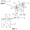
Фиг.2 изображает деталь установки согласно изобретению.Figure 2 depicts a detail of the installation according to the invention.
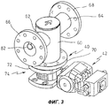
Фиг.3 изображает в перспективе загрузочный клапан для установки согласно Фиг.1.Figure 3 depicts in perspective a loading valve for installation according to Figure 1.
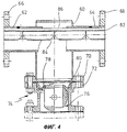
Фиг.4 изображает разрез через загрузочный клапан согласно Фиг.3. Figure 4 depicts a section through a loading valve according to Figure 3.
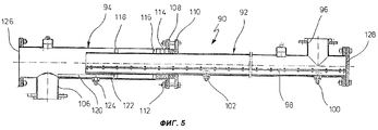
Фиг.5 изображает в разрезе транспортный желоб для установки согласно Фиг.1.Figure 5 depicts a sectional transport chute for installation according to Figure 1.
Сведения, подтверждающие возможность осуществления изобретенияInformation confirming the possibility of carrying out the invention
На Фиг.1 виден резервуар-накопитель 10, который содержит, например, порошок окиси алюминия. Порошок через трубопровод 12, который содержит сито и, как минимум, одно запорное устройство, через которое он не может пройти дальше, транспортируется к резервуару высокого давления 14. Резервуар высокого давления соединен с трубопроводом пневматического транспорта 16. Резервуар высокого давления связан с трубопроводом сжатого воздуха 18, который подключен к компрессору 20 или к сети подачи сжатого воздуха. Трубопровод сжатого воздуха 18 ведет, во-первых, к верхнему концу резервуара высокого давления 14 и, во-вторых, к его нижнему концу, как видно из Фиг.1. Кроме того, отвод 22 идет непосредственно к подающему трубопроводу 16. С помощью указанной системы сыпучий материал, в данном случае порошок окиси алюминия, транспортируется по подающему трубопроводу 16 так, что даже в случае необходимости транспорта на относительно большое расстояние не возникают слишком большие потери давления и не происходит слишком большое снижение давления.Figure 1 shows the reservoir tank 10, which contains, for example, alumina powder. The powder through the pipe 12, which contains a sieve and at least one shut-off device through which it cannot pass further, is transported to the high-pressure tank 14. The high-pressure tank is connected to the
Через определенные промежутки по длине к трубопроводу пневматического транспорта 16 подключены отводы трубопровода 24, каждый из которых ведет к приемному резервуару 26. К нижним концам приемных резервуаров 26 с противоположных сторон подключены пневматические транспортные желоба 28, 30. Пневматические транспортные желоба 28, 30, которые снабжаются сжатым воздухом от компрессора 32, ведут к отдельным печам для выплавки алюминия 34,36, причем для каждой камеры печей 34 предусмотрены один или несколько отводов транспортного желоба 30, как показано, например, под номером 38.At certain intervals along the length of the
На Фиг.2 приведены увеличенные изображения двух приемных резервуаров 26. Понятно, что в каждом из отводов 24 расположен клапан 40, который управляется пневматическим управляющим устройством 42.Figure 2 shows enlarged images of two receiving
В приемном резервуаре 26, который имеет характерный для установки объем, равный, например, 0,5 м3, предусмотрено устройство для измерения уровня заполнения 44, которое определяет, когда уровень в резервуаре 26 достигает максимального значения. В этом случае клапан 40 закрывается. Он снова открывается, когда проходит заданное время, или если при следующем измерении уровня заполнения в резервуаре 26 определен минимальный уровень.In the receiving
К клапанам 40 относится также контрольное устройство, которое образовано, например, концевыми выключателями, как показано кругом из тире и точек 46. Оно определяет, занял после подачи сигнала к срабатыванию клапана 40 этот клапан должное положение или нет, что может быть определено, например, с помощью концевого выключателя. Это может быть показано, например, на мониторе 48.
Из Фиг.2 далее можно видеть, как транспортный желоб 28 связан с двумя камерами 50, 52 печи 36 или 34.From FIG. 2, it can further be seen how the
Приемные резервуары 26 соединены трубопроводами 56 с газоотводящим каналом 58. В него поступает воздух, выходящий из приемного резервуара, когда он заполняется через трубопровод пневматического транспорта 16.The receiving
Во время работы порошок окиси алюминия подается в подающий трубопровод 16 и при открытом клапане 42 - в приемный резервуар. Так как потребление порошка печами для выплавки алюминия 34, 36 известно, не требуется особая регулировка или задание регулируемых количеств, подаваемых в единицу времени. Конечно, можно предусмотреть также соответствующую регулировку или остановку подачи, если имеются соответствующие условия.During operation, the alumina powder is supplied to the
На фиг.3 и 4 более крупно изображен клапан 40. Из Фиг.3 видно, что клапан расположен на нижнем конце цилиндрического резервуара 60, с противоположными сторонами которого соединены участки труб 62, 64, например посредством сварки. На концах участков труб 62, 64 находятся фланцы 66, 68 для подключения к соответствующему концу подающего трубопровода 16 (не показан). К нижнему концу цилиндрического резервуара 60 приварен фланец 70 для соединения с верхним фланцем 72 корпуса 74 клапана 40.Figure 3 and 4 shows a
В цилиндрическом корпусе 74 клапана шар 76 клапана перемещается вокруг горизонтальной оси. Управление шаром 76 клапана для поворота его на угол ±90° осуществляется через пневматическое управляющее устройство 42, которое нет надобности описывать подробно, так как устройства такого рода относятся к современному уровню техники.In the
Как можно видеть из двух различных положений на Фиг.4, с помощью шара 76 клапана можно открыть или закрыть проход вниз из цилиндрического резервуара 60. С этой целью между переходником корпуса 74 и зажимным кольцом 80 зажимают упругую кольцевую прокладку 78, которая под зажимающим усилием изгибается вверх и прижимается к наружной стороне шара 76 клапана. В закрытом положении шара 76 клапана с помощью прокладки 78 проход вниз закрывается. Так как в приемном резервуаре 26 давление намного меньше, чем в подающем трубопроводе 16, разность давлений на уплотнительном кольце 78 приводит к тому, что оно с относительно большой силой прижимается к наружной стороне шара 76 клапана. Впрочем, между шаром 76 и корпусом 74 имеется достаточно большое свободное пространство, так что материал не может здесь осесть и изменить проходимость шара 76 клапана.As can be seen from two different positions in FIG. 4, a
Следует упомянуть, что в подающем трубопроводе 16 и, соответственно, также в звеньях трубопровода 62, 64 расположена, например, меньшая по диаметру труба 82 для подачи сжатого воздуха, в которой через определенные расстояния имеются направленные вниз вырезанные отверстия 84, в области которых расположена заслонка 86. Такого рода исполнение трубопровода пневматического транспорта также хорошо известно.It should be noted that in the
На Фиг.5 под номером 90 показан пример транспортного желоба, который составлен из первого, имеющего форму трубы, участка 92 желоба и второго, имеющего форму трубы, участка 94, причем последний телескопически взаимодействует с первым. Участок 92 желоба через боковой штуцер 96 связан с не показанным на чертеже приемным резервуаром, например с приемным резервуаром 26 согласно Фиг.1 и 2. Он в нижней части содержит проницаемую для воздуха ткань 98 желоба, который через штуцеры 100 и/или 102 подключен к сжатому воздуху с целью разрыхления материала, который через патрубок 96 поступает в желоб 90. Второй участок 94 имеет отводящий патрубок 106, который жестко соединен с камерой печи для выплавки алюминия или другим транспортным желобом. Транспортный желоб при этом может быть приспособлен к требуемым пространственным характеристикам в продольном направлении.5,
Имеющий форму трубы участок 94 на одном конце снабжен фланцем 108, который соединен с кольцом 110 с помощью винтов 112 с целью натяжения уплотнительной набивки 114, которая через прокладку 116 с боков трубки прижимается к кольцу, приваренному к участку 94. Следующее кольцо 118 внутри участка 94 служит для сообщения между участками 92, 94.The pipe-shaped
На втором участке 94 под номером 120 показан перфорированный поддон 120, который образует нижний участок 122 желоба, снабженный устройством 124 для подачи сжатого воздуха для разрыхления материала, который поступает из первого участка 92 во второй участок 94, прежде чем он попадет в штуцер 106. Конец второго участка 94 закрыт глухим фланцем 126.In the
Также можно предусмотреть на втором участке через определенные расстояния многочисленные патрубки, каждый их которых соединен с электролитической ячейкой печи для выплавки алюминия. В этом случае между патрубками или отводами также можно предусмотреть возможность разрыхления, как это показано под номером 120.You can also provide in the second section through certain distances numerous nozzles, each of which is connected to the electrolytic cell of the furnace for smelting aluminum. In this case, it is also possible to provide for the possibility of loosening between the nozzles or branches, as shown under the
Правый конец первого участка 92 желоба также герметично закрыт глухим фланцем под номером 128.The right end of the
Установку, изображенную на Фиг.1-5 и описанную выше, можно использовать для других потребителей сыпучих материалов.The installation depicted in FIGS. 1-5 and described above can be used for other bulk materials consumers.
Claims (9)
Applications Claiming Priority (2)
| Application Number | Priority Date | Filing Date | Title |
|---|---|---|---|
| DE10162398.4 | 2001-12-13 | ||
| DE10162398A DE10162398A1 (en) | 2001-12-13 | 2001-12-13 | System for feeding a plurality of consumers, e.g. B. cells of aluminum melting furnaces with bulk material, for. B. powdered alumina |
Publications (2)
| Publication Number | Publication Date |
|---|---|
| RU2002132865A RU2002132865A (en) | 2004-06-27 |
| RU2258024C2 true RU2258024C2 (en) | 2005-08-10 |
Family
ID=7709807
Family Applications (1)
| Application Number | Title | Priority Date | Filing Date |
|---|---|---|---|
| RU2002132865/02A RU2258024C2 (en) | 2001-12-13 | 2002-12-09 | Plant for charging several consumers with loose material, for instance, loading of aluminium melting furnace chambers with power alumina |
Country Status (14)
| Country | Link |
|---|---|
| US (1) | US6749373B2 (en) |
| EP (1) | EP1319615B1 (en) |
| CN (1) | CN1223501C (en) |
| AT (1) | ATE276950T1 (en) |
| AU (1) | AU2002317516B8 (en) |
| CA (1) | CA2414430C (en) |
| DE (2) | DE10162398A1 (en) |
| DK (1) | DK1319615T3 (en) |
| ES (1) | ES2225718T3 (en) |
| NO (1) | NO326869B1 (en) |
| PT (1) | PT1319615E (en) |
| RO (1) | RO121388B1 (en) |
| RU (1) | RU2258024C2 (en) |
| TR (1) | TR200402506T4 (en) |
Cited By (4)
| Publication number | Priority date | Publication date | Assignee | Title |
|---|---|---|---|---|
| RU2407826C1 (en) * | 2009-07-09 | 2010-12-27 | ЮНАЙТЕД КОМПАНИ РУСАЛ Ай Пи ЛИМИТЕД | System of automatic supply of raw material to aluminium electrolyser |
| RU2506350C1 (en) * | 2012-08-10 | 2014-02-10 | Общество с ограниченной ответственностью "Объединенная Компания РУСАЛ Инженерно-технологический центр" | System of automatic supply of raw material to electrolysis units with self-baking anodes |
| RU2561940C1 (en) * | 2014-04-22 | 2015-09-10 | Общество с ограниченной ответственностью "Объединенная Компания РУСАЛ Инженерно-технологический центр" | System for automatic raw material supply to electrolysers with self-baking anodes |
| RU2639911C2 (en) * | 2011-09-19 | 2017-12-25 | Тюссенкрупп Индастриал Солюшнс Аг | Method and installation for synthesis-gas production by gasification of biomassis in pseudofluidized layer |
Families Citing this family (22)
| Publication number | Priority date | Publication date | Assignee | Title |
|---|---|---|---|---|
| NO315037B1 (en) | 2001-03-21 | 2003-06-30 | Norsk Hydro As | Method and system for distributing fluidizable materials |
| FR2831528B1 (en) * | 2001-10-26 | 2004-01-16 | Pechiney Aluminium | POWDER MATERIAL DISTRIBUTION SYSTEM WITH CONTROLLED WEIGHTS |
| EP1623941A1 (en) * | 2004-08-05 | 2006-02-08 | Alcan Technology & Management Ltd. | System and method for pneumatically conveying of free-flowing products in a dense flow |
| CN100420617C (en) * | 2005-10-12 | 2008-09-24 | 沈阳铝镁设计研究院 | Bottom discharge structure and discharge method of alumina silo |
| CN101397681B (en) * | 2007-09-29 | 2012-05-23 | 沈阳铝镁设计研究院有限公司 | Horizontal strip type fluidized material distribution device |
| LU91376B1 (en) * | 2007-11-16 | 2009-05-18 | Wurth Paul Sa | Injections system for solid particles |
| US8951315B2 (en) * | 2008-11-12 | 2015-02-10 | Exxonmobil Research And Engineering Company | Method of injecting fuel into a gasifier via pressurization |
| FR2952363B1 (en) * | 2009-11-09 | 2011-11-11 | Alcan Int Ltd | POTENTIALLY FLUIDIZING DEVICE FOR CONVEYING PULVERULENT MATERIALS IN HYPERDENSE BED |
| US8784013B2 (en) * | 2010-01-08 | 2014-07-22 | The Gsi Group, Llc | Pneumatic grain conveying apparatus and method for selectively discharging grain or by-passing the discharge of grain into a grain bin |
| CN102466104B (en) * | 2010-11-08 | 2015-08-26 | 通用电气公司 | Pipeline and delivery method |
| CN102327805A (en) * | 2011-09-30 | 2012-01-25 | 姜本熹 | Method and device for charging grinder |
| FR2980783B1 (en) * | 2011-10-04 | 2016-05-13 | Rio Tinto Alcan Int Ltd | METHOD AND DEVICE FOR DISTRIBUTING A FLUIDIZABLE MATERIAL, AND INSTALLATION INCLUDING SAID DEVICE |
| EP2757298A1 (en) * | 2013-05-29 | 2014-07-23 | Tata Steel Nederland Technology B.V. | Supply pipe with telescoping pipe parts |
| CN105753028B (en) * | 2016-04-06 | 2017-04-05 | 沈阳鑫博工业技术股份有限公司 | A kind of volume formula blows powder device and its using method |
| CN107352273A (en) * | 2017-07-03 | 2017-11-17 | 聊城信源集团有限公司 | A kind of aluminum oxide Transmission system and its transmission method |
| US10421625B2 (en) * | 2017-09-08 | 2019-09-24 | Cnh Industrial Canada, Ltd. | System and method for removing blockages present in a delivery conduit of a seeder |
| DE102019001471A1 (en) * | 2019-02-27 | 2020-08-27 | Walter Kramer | Suction conveyor system for bulk goods, in particular plastic granulate |
| EP3947218B1 (en) * | 2019-04-04 | 2025-12-31 | Reel Alesa AG | PRECISION FLOW FEEDING DEVICE |
| GB201906310D0 (en) * | 2019-05-03 | 2019-06-19 | Schenck Process Uk Ltd | Material conveying apparatus with shut down valves |
| CN112598233B (en) * | 2020-03-12 | 2024-07-26 | 吴敏 | Quality and safety monitoring and management system for powder metallurgy production |
| US12510077B2 (en) | 2021-07-08 | 2025-12-30 | Industrial Vacuum Transfer Services Usa, Llc | Air compressor having vacuum and associated methods for loading and extracting materials |
| US12485459B2 (en) * | 2021-07-08 | 2025-12-02 | Industrial Vacuum Transfer Services Usa, Llc | Systems, assemblies, and methods for pyrophoric material extraction |
Family Cites Families (16)
| Publication number | Priority date | Publication date | Assignee | Title |
|---|---|---|---|---|
| US3945683A (en) * | 1969-07-09 | 1976-03-23 | Fiber Controls Corporation | Priority interrupt circuit |
| US3753867A (en) * | 1971-04-14 | 1973-08-21 | Koppers Gmbh Heinrich | Apparatus for charging coke ovens |
| US3689045A (en) * | 1971-06-03 | 1972-09-05 | Earl E Coulter | Pulverized fuel delivery system for a blast furnace |
| US4027920A (en) * | 1975-10-14 | 1977-06-07 | The Babcock & Wilcox Company | Distributor |
| DE3042661A1 (en) * | 1980-11-12 | 1982-06-16 | Waeschle Maschinenfabrik Gmbh, 7980 Ravensburg | METHOD AND SYSTEM FOR SUPPLYING SEVERAL BURNERS OF A COMBUSTION SYSTEM WITH GRAINED OR POWDERED FUEL |
| JPS58104833A (en) * | 1981-12-12 | 1983-06-22 | Kawasaki Steel Corp | Continuously supplying method and device for transporting granule from one distributive transportation tank to plural supply ends by controlling mass flow to optional preset value |
| FR2534891B1 (en) * | 1982-10-22 | 1987-01-09 | Pechiney Aluminium | CLOSED POTENTIAL FLUIDIZATION DEVICE FOR HORIZONTAL CONTROL OF POWDER MATERIALS |
| JPS59124624A (en) * | 1982-12-27 | 1984-07-18 | Kawasaki Steel Corp | Method for distribution and transport of pulverized/ granular material |
| NL183951C (en) * | 1983-01-12 | 1989-03-01 | Hoogovens Groep Bv | DOSING DEVICE FOR DOSING POWDER COAL IN AN AIR LINE TO A MAIN OVEN. |
| DE3310452A1 (en) * | 1983-03-23 | 1984-09-27 | Bühler-Miag GmbH, 3300 Braunschweig | METHOD AND DEVICE FOR THE AUTOMATIC PNEUMATIC LOADING OF A VARIETY OF CONSUMPTION POINTS WITH POWDERED GOODS |
| FR2562878B2 (en) * | 1984-04-12 | 1989-06-30 | Pechiney Aluminium | CLOSED POTENTIAL FLUIDIZATION DEVICE FOR HORIZONTAL CONVEYANCE IN DENSE BED OF POWDER MATERIALS |
| EP0224436B1 (en) | 1985-10-31 | 1989-07-26 | Schweizerische Aluminium Ag | Device for charging bulk material containers, and its use |
| DE3603078C1 (en) * | 1986-02-01 | 1987-10-22 | Kuettner Gmbh & Co Kg Dr | Method and device for the metered introduction of fine-grained solids into an industrial furnace, in particular a blast furnace or cupola furnace |
| US4774893A (en) * | 1987-08-13 | 1988-10-04 | Kinergy Corporation | System of handling refuse derived fuel utilizing same to fire power plants |
| US4938848A (en) * | 1989-02-13 | 1990-07-03 | Aluminum Company Of America | Method and apparatus for conveying split streams of alumina powder to an electrolysis cell |
| US6332408B2 (en) * | 2000-01-13 | 2001-12-25 | Michael Howlett | Pressure feedback signal to optimise combustion air control |
-
2001
- 2001-12-13 DE DE10162398A patent/DE10162398A1/en not_active Ceased
-
2002
- 2002-12-03 EP EP02027023A patent/EP1319615B1/en not_active Expired - Lifetime
- 2002-12-03 TR TR2004/02506T patent/TR200402506T4/en unknown
- 2002-12-03 ES ES02027023T patent/ES2225718T3/en not_active Expired - Lifetime
- 2002-12-03 PT PT02027023T patent/PT1319615E/en unknown
- 2002-12-03 DK DK02027023T patent/DK1319615T3/en active
- 2002-12-03 DE DE50201083T patent/DE50201083D1/en not_active Expired - Lifetime
- 2002-12-03 AT AT02027023T patent/ATE276950T1/en active
- 2002-12-09 RU RU2002132865/02A patent/RU2258024C2/en active
- 2002-12-10 RO ROA200201580A patent/RO121388B1/en unknown
- 2002-12-11 CA CA002414430A patent/CA2414430C/en not_active Expired - Lifetime
- 2002-12-11 AU AU2002317516A patent/AU2002317516B8/en not_active Expired
- 2002-12-12 NO NO20025986A patent/NO326869B1/en not_active IP Right Cessation
- 2002-12-13 CN CN02154226.0A patent/CN1223501C/en not_active Expired - Fee Related
- 2002-12-13 US US10/318,829 patent/US6749373B2/en not_active Expired - Lifetime
Cited By (4)
| Publication number | Priority date | Publication date | Assignee | Title |
|---|---|---|---|---|
| RU2407826C1 (en) * | 2009-07-09 | 2010-12-27 | ЮНАЙТЕД КОМПАНИ РУСАЛ Ай Пи ЛИМИТЕД | System of automatic supply of raw material to aluminium electrolyser |
| RU2639911C2 (en) * | 2011-09-19 | 2017-12-25 | Тюссенкрупп Индастриал Солюшнс Аг | Method and installation for synthesis-gas production by gasification of biomassis in pseudofluidized layer |
| RU2506350C1 (en) * | 2012-08-10 | 2014-02-10 | Общество с ограниченной ответственностью "Объединенная Компания РУСАЛ Инженерно-технологический центр" | System of automatic supply of raw material to electrolysis units with self-baking anodes |
| RU2561940C1 (en) * | 2014-04-22 | 2015-09-10 | Общество с ограниченной ответственностью "Объединенная Компания РУСАЛ Инженерно-технологический центр" | System for automatic raw material supply to electrolysers with self-baking anodes |
Also Published As
| Publication number | Publication date |
|---|---|
| EP1319615A3 (en) | 2003-12-10 |
| TR200402506T4 (en) | 2004-12-21 |
| DE50201083D1 (en) | 2004-10-28 |
| DE10162398A1 (en) | 2003-07-24 |
| CA2414430A1 (en) | 2003-06-13 |
| DK1319615T3 (en) | 2005-01-31 |
| US20030116406A1 (en) | 2003-06-26 |
| AU2002317516B2 (en) | 2008-03-20 |
| EP1319615B1 (en) | 2004-09-22 |
| AU2002317516B8 (en) | 2008-04-17 |
| RO121388B1 (en) | 2007-04-30 |
| US6749373B2 (en) | 2004-06-15 |
| CA2414430C (en) | 2007-01-23 |
| PT1319615E (en) | 2004-12-31 |
| NO20025986D0 (en) | 2002-12-12 |
| NO326869B1 (en) | 2009-03-09 |
| ES2225718T3 (en) | 2005-03-16 |
| ATE276950T1 (en) | 2004-10-15 |
| NO20025986L (en) | 2003-06-16 |
| CN1223501C (en) | 2005-10-19 |
| CN1432525A (en) | 2003-07-30 |
| HK1056156A1 (en) | 2004-02-06 |
| EP1319615A2 (en) | 2003-06-18 |
Similar Documents
| Publication | Publication Date | Title |
|---|---|---|
| AU2002317516B8 (en) | Installation for Feeding a Plurality of Loads, e.g. Cells of Aluminium Melting Furnaces, with Bulk Material, e.g. Pulverised aluminium Oxide | |
| US4111492A (en) | Pneumatic conveying apparatus and method | |
| US8425160B2 (en) | Drill cuttings storage and conveying | |
| RU2002132865A (en) | INSTALLATION FOR DOWNLOADING MULTIPLE CONSUMERS OF BULK MATERIAL, FOR EXAMPLE FOR DOWNLOADING CASES OF FUSION FURNACE FOR ALUMINUM POWDER ALUMINUM OXIDE | |
| SK11782003A3 (en) | A method and system for distribution of fluidisable materials | |
| NO160130B (en) | CLOSED APPLIANCE FOR POTENTIAL FLUIDIZATION OF POWDER MATERIAL. | |
| CN101605594B (en) | Method and apparatus for separating a solids stream | |
| ME01417B (en) | Method and an arrangement for filling a silo | |
| NZ194722A (en) | Aluminium electrolytic cell:automatic alumina pneumatic feed system | |
| US4773797A (en) | Device for loading containers for particulate materials and the use thereof | |
| SI9400112A (en) | Pouring device with a part for regulation of stream velocity | |
| CN102712428B (en) | Silo with filling unit | |
| NO821017L (en) | DEVICE FOR DOSAGE DOSAGE OF FLUIDIZABLE LODGE | |
| RU2328437C2 (en) | Plant for continuous feed of powdered hard material into pneumatic transport pipeline | |
| CN208616562U (en) | A kind of autocontrol storage bin | |
| CN113650819A (en) | Device for conveying material | |
| HK1056156B (en) | Installation for feeding a plurality of loads with bulk material | |
| US20250368456A1 (en) | Flow rate adjustment device | |
| EP2389533B1 (en) | A valve unit for pressure vessels | |
| US3090685A (en) | Method for charging dry gasifiers with calcium carbide | |
| RU2115611C1 (en) | Powder-like material pneumatic transportation method | |
| CN109931424B (en) | Pneumatic feeding system | |
| CA1161476A (en) | System for preventing clogging of the outlet orifice of a dispenser tank containing powdered reagent and auxiliary tank discharge means | |
| GB2118152A (en) | System for preventing clogging of the outlet orifice of a dispenser tank | |
| CS270630B1 (en) | Device for weighing bulk materials in a container, especially dispensers |
Legal Events
| Date | Code | Title | Description |
|---|---|---|---|
| PC41 | Official registration of the transfer of exclusive right |
Effective date: 20120517 |