RU2262425C1 - Titanium alloy electric arc welding method - Google Patents
Titanium alloy electric arc welding method Download PDFInfo
- Publication number
- RU2262425C1 RU2262425C1 RU2004103525/02A RU2004103525A RU2262425C1 RU 2262425 C1 RU2262425 C1 RU 2262425C1 RU 2004103525/02 A RU2004103525/02 A RU 2004103525/02A RU 2004103525 A RU2004103525 A RU 2004103525A RU 2262425 C1 RU2262425 C1 RU 2262425C1
- Authority
- RU
- Russia
- Prior art keywords
- welding
- passes
- gap
- edges
- dressing
- Prior art date
Links
- 238000003466 welding Methods 0.000 title claims abstract description 25
- 238000000034 method Methods 0.000 title claims abstract description 15
- 229910001069 Ti alloy Inorganic materials 0.000 title claims abstract description 6
- 238000010891 electric arc Methods 0.000 title 1
- WFKWXMTUELFFGS-UHFFFAOYSA-N tungsten Chemical compound [W] WFKWXMTUELFFGS-UHFFFAOYSA-N 0.000 claims abstract description 10
- 229910052721 tungsten Inorganic materials 0.000 claims abstract description 10
- 239000010937 tungsten Substances 0.000 claims abstract description 10
- 239000000463 material Substances 0.000 claims abstract description 5
- 238000005520 cutting process Methods 0.000 claims description 8
- 229910052751 metal Inorganic materials 0.000 claims description 6
- 239000002184 metal Substances 0.000 claims description 6
- 239000000155 melt Substances 0.000 claims description 5
- 239000000945 filler Substances 0.000 claims description 4
- 238000006073 displacement reaction Methods 0.000 claims description 2
- 239000011261 inert gas Substances 0.000 abstract description 2
- 238000004519 manufacturing process Methods 0.000 abstract description 2
- 239000000126 substance Substances 0.000 abstract description 2
- 230000004927 fusion Effects 0.000 abstract 2
- 230000001154 acute effect Effects 0.000 abstract 1
- 239000000654 additive Substances 0.000 abstract 1
- 230000000996 additive effect Effects 0.000 abstract 1
- 230000000694 effects Effects 0.000 abstract 1
- 230000035515 penetration Effects 0.000 description 3
- 238000005238 degreasing Methods 0.000 description 2
- 239000000203 mixture Substances 0.000 description 2
- 238000004140 cleaning Methods 0.000 description 1
- 230000006866 deterioration Effects 0.000 description 1
- 238000001035 drying Methods 0.000 description 1
- 239000008187 granular material Substances 0.000 description 1
- 238000011089 mechanical engineering Methods 0.000 description 1
- 150000002739 metals Chemical class 0.000 description 1
- 230000003647 oxidation Effects 0.000 description 1
- 238000007254 oxidation reaction Methods 0.000 description 1
- 238000002360 preparation method Methods 0.000 description 1
- 230000007704 transition Effects 0.000 description 1
Images
Landscapes
- Arc Welding In General (AREA)
- Butt Welding And Welding Of Specific Article (AREA)
Abstract
Description
Изобретение относится к автоматической сварке активных металлов в среде инертных газов погруженным вольфрамовым электродом и может быть использовано в машиностроении при сварке соединений преимущественно повышенной толщины.The invention relates to automatic welding of active metals in an inert gas environment by a submerged tungsten electrode and can be used in mechanical engineering when welding joints of predominantly increased thickness.
Известно, что для сварки поверхностной дугой соединений толщиной более 6-8 мм используют многопроходную сварку с различной подготовкой кромок свариваемых деталей (ГОСТ 8713-70 "Швы сварных соединений. Автоматическая и полуавтоматическая сварка").It is known that for welding with a surface arc of joints with a thickness of more than 6-8 mm, multi-pass welding with different preparation of the edges of the parts to be welded is used (GOST 8713-70 "Weld seams. Automatic and semi-automatic welding").
Недостатком известного способа является опасность ухудшения качества сварного шва из-за окисления (при нарушении по каким-либо причинам защиты шва) поверхности валика и переходе оксидов в металл шва при последующем проходе. Неоднократная зачистка поверхности сварного шва перед каждым проходом с последующим обезжириванием и просушкой приводит к нежелательному увеличению длительности производственного процесса.The disadvantage of this method is the danger of deterioration in the quality of the weld due to oxidation (if the protection of the seam is violated for any reason) of the surface of the roller and the transition of oxides into the weld metal during subsequent passage. Repeated cleaning of the weld surface before each pass, followed by degreasing and drying, leads to an undesirable increase in the duration of the production process.
Наиболее близким к заявленному техническому решению, принятому за прототип, является способ сварки титановых сплавов погруженным вольфрамовым электродом по щелевому зазору, заполненному гранулированным присадочным материалом (см. SU 1838061 A1, B 23 K 9/167, 30.08.1993).Closest to the claimed technical solution adopted for the prototype is a method of welding titanium alloys with a submerged tungsten electrode along a slit gap filled with granular filler material (see SU 1838061 A1, B 23 K 9/167, 08/30/1993).
К недостаткам известного способа можно отнести отсутствие возможности однопроходной сварки соединений, толщина которых превышает предельную для выбранного сварочного оборудования (источника питания).The disadvantages of this method include the lack of the possibility of single-pass welding of joints whose thickness exceeds the limit for the selected welding equipment (power source).
Заявленное изобретение направлено на расширение технологических возможностей способа сварки погруженным вольфрамовым электродом за счет увеличения предельной толщины свариваемых деталей.The claimed invention is aimed at expanding the technological capabilities of the method of welding by immersed tungsten electrode by increasing the ultimate thickness of the welded parts.
Сущность заявленного изобретения состоит в том, что в способе многопроходной автоматической дуговой сварки титановых сплавов погруженным вольфрамовым электродом по щелевому зазору, при котором используют гранулированный присадочный материал, засыпаемый перед сваркой в щелевой зазор, на свариваемых кромках выполняют вырез, который при сборке деталей с щелевым зазором формируется в виде П-образной разделки кромок с отношением глубины разделки к ее ширине менее 1, при этом острые углы разделки скругляют.The essence of the claimed invention lies in the fact that in the method of multi-pass automatic arc welding of titanium alloys by immersed tungsten electrode along the slot gap, in which granular filler material is used, which is poured into the slot gap before welding, a cut is made on the welded edges, which when assembling parts with a gap gap formed in the form of a U-shaped groove of the edges with a ratio of the depth of groove to its width less than 1, while the sharp corners of the groove are rounded.
Кроме того, в данном способе для гарантированного заполнения П-образной разделки расплавленным металлом второй и третий проходы осуществляют на одинаковом режиме с соблюдением следующих соотношений Н·k≤30 и у=(Е+2Н)/2,In addition, in this method for guaranteed filling of the U-shaped groove with molten metal, the second and third passes are carried out in the same mode in compliance with the following ratios Н · k≤30 and у = (Е + 2Н) / 2,
где Н - глубина П-образной разделки, мм;where H is the depth of the U-shaped cutting, mm;
Е - ширина П-образной разделки, мм;E - the width of the U-shaped cutting, mm;
k - коэффициент формы проплава;k is the melt shape coefficient;
у - смещение вольфрамового электрода от оси стыка, мм.y is the displacement of the tungsten electrode from the axis of the joint, mm
Кроме того, в данном способе округление кромок П-образной разделки выполняют соответствующим форме поперечного сечения сварного шва при втором и третьем проходах.In addition, in this method, the rounding of the edges of the U-shaped grooves is performed corresponding to the cross-sectional shape of the weld in the second and third passes.
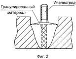
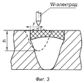
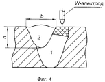
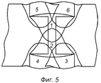
Изобретение поясняется чертежами, где на фиг.1 представлены свариваемые кромки с П-образным вырезом, собранные со щелевым зазором для случая двусторонней сварки; на фиг.2 - выполнение первого прохода; на фиг.3 - выполнение второго прохода; на фиг.4 - выполнение третьего прохода; на фиг.5 - порядок выполнения проходов при двусторонней сварке.The invention is illustrated by drawings, where Fig. 1 shows welded edges with a U-shaped cut, assembled with a gap in the gap for double-sided welding; figure 2 - the implementation of the first pass; figure 3 - the implementation of the second pass; figure 4 - the implementation of the third passage; figure 5 - the execution order of the passes in two-sided welding.
Основные геометрические параметры разделки кромок (Е, Н и t) зависят от толщины свариваемого металла δ и особенностей применяемой сварочной аппаратуры. Ширина П-образной разделки Е составляет сумму выборок на обеих кромках S и ширины щелевого зазора t. Значение Е выбирают равным ширине сварного шва (в его верхней части), b - при втором и третьем проходе или с небольшими отклонениями от b. В П-образной разделке наибольшую опасность для гарантированного провара представляют острые углы (показаны пунктиром на фиг.1). Поэтому острые углы скругляют, а угол наклона округления выбирают исходя из коэффициента формы проплава k или экспериментально.The main geometric parameters for cutting edges (E, H, and t) depend on the thickness of the metal being welded δ and the characteristics of the welding equipment used. The width of the U-shaped groove E is the sum of the samples at both edges S and the width of the gap gap t. The value of E is chosen equal to the width of the weld (in its upper part), b - in the second and third pass or with slight deviations from b. In a U-shaped cut, the greatest danger to guaranteed penetration is represented by sharp corners (shown by a dotted line in FIG. 1). Therefore, sharp angles are rounded, and the angle of inclination of the rounding is selected based on the shape factor k or experimentally.
Способ автоматической дуговой сварки титановых сплавов погруженным электродом осуществляют следующим образом. На свариваемых кромках выполняют заранее такой вырез, который при сборке деталей со щелевым зазором формируется в виде П-образной разделки кромок с отношением глубины разделки к ее ширине менее 1. Затем щелевой зазор заполняют гранулированным присадочным материалом и выполняют первый проход (фиг.2) с минимально возможным значением коэффициента формы проплава.The method of automatic arc welding of titanium alloys with a submerged electrode is as follows. On the welded edges, a cut is made in advance, which, when assembling parts with a gap, is formed in the form of a U-shaped groove with a ratio of depth of cutting to its width less than 1. Then, the gap is filled with granular filler material and the first pass is performed (Fig. 2) the minimum possible value of the melt form factor.
В случае необходимости поверхность сварного шва после первого прохода зачищают металлической щеткой с последующим обезжириванием и заполняют П-образную разделку гранулированным материалом того же состава, что и в щелевом зазоре, или другого химического состава. Для гарантированного проплавления стенок разделки и последующего перекрытия проваров от второго и третьего проходов электрод устанавливают со смещением от оси стыка у=(Е+2Н)/2 (фиг.3), а коэффициент формы проплава k подбирают в зависимости от глубины выборки Н по формуле Н·k≤30. Коэффициент формы проплава изменяют в нужном направлении путем изменения геометрических параметров вольфрамового электрода и величиной его заглубления. Третий проход осуществляют на том же режиме, что и второй (фиг.4).If necessary, the surface of the weld after the first pass is cleaned with a wire brush, followed by degreasing and the U-shaped cut is filled with granular material of the same composition as in the gap gap, or of a different chemical composition. For guaranteed penetration of the walls of the grooves and subsequent overlap of the weld from the second and third passes, the electrode is installed with an offset from the axis of the joint y = (E + 2H) / 2 (Fig. 3), and the shape factor of the melt k is selected depending on the sample depth H by the formula N · k≤30. The shape factor of the melt is changed in the right direction by changing the geometric parameters of the tungsten electrode and the depth of its penetration. The third pass is carried out in the same mode as the second (figure 4).
Предлагаемый способ сварки с использованием погруженного вольфрамового электрода позволяет в 1,5 раза увеличить толщину свариваемого металла.The proposed welding method using a submerged tungsten electrode allows 1.5 times to increase the thickness of the welded metal.
Claims (3)
Priority Applications (1)
| Application Number | Priority Date | Filing Date | Title |
|---|---|---|---|
| RU2004103525/02A RU2262425C1 (en) | 2004-02-06 | 2004-02-06 | Titanium alloy electric arc welding method |
Applications Claiming Priority (1)
| Application Number | Priority Date | Filing Date | Title |
|---|---|---|---|
| RU2004103525/02A RU2262425C1 (en) | 2004-02-06 | 2004-02-06 | Titanium alloy electric arc welding method |
Publications (2)
| Publication Number | Publication Date |
|---|---|
| RU2004103525A RU2004103525A (en) | 2005-07-20 |
| RU2262425C1 true RU2262425C1 (en) | 2005-10-20 |
Family
ID=35842164
Family Applications (1)
| Application Number | Title | Priority Date | Filing Date |
|---|---|---|---|
| RU2004103525/02A RU2262425C1 (en) | 2004-02-06 | 2004-02-06 | Titanium alloy electric arc welding method |
Country Status (1)
| Country | Link |
|---|---|
| RU (1) | RU2262425C1 (en) |
Cited By (2)
| Publication number | Priority date | Publication date | Assignee | Title |
|---|---|---|---|---|
| CN108637518A (en) * | 2018-05-16 | 2018-10-12 | 四川石油天然气建设工程有限责任公司 | Welding groove and welding method of oil and gas composite transportation pipeline |
| RU189271U1 (en) * | 2019-01-23 | 2019-05-17 | Публичное акционерное общество "Челябинский трубопрокатный завод" (ПАО "ЧТПЗ") | Blank for the manufacture of large diameter steel pipe |
Citations (3)
| Publication number | Priority date | Publication date | Assignee | Title |
|---|---|---|---|---|
| RU2133178C1 (en) * | 1997-12-09 | 1999-07-20 | Комсомольское-на-Амуре авиационное производственное объединение | Titanium alloy argon arc welding method |
| JP2000102890A (en) * | 1998-09-29 | 2000-04-11 | Mitsubishi Heavy Ind Ltd | Welding method, welding joint and welding structure |
| JP2002224836A (en) * | 2001-02-07 | 2002-08-13 | Nippon Steel Weld Prod & Eng Co Ltd | Titanium or titanium alloy welding method |
-
2004
- 2004-02-06 RU RU2004103525/02A patent/RU2262425C1/en not_active IP Right Cessation
Patent Citations (3)
| Publication number | Priority date | Publication date | Assignee | Title |
|---|---|---|---|---|
| RU2133178C1 (en) * | 1997-12-09 | 1999-07-20 | Комсомольское-на-Амуре авиационное производственное объединение | Titanium alloy argon arc welding method |
| JP2000102890A (en) * | 1998-09-29 | 2000-04-11 | Mitsubishi Heavy Ind Ltd | Welding method, welding joint and welding structure |
| JP2002224836A (en) * | 2001-02-07 | 2002-08-13 | Nippon Steel Weld Prod & Eng Co Ltd | Titanium or titanium alloy welding method |
Cited By (2)
| Publication number | Priority date | Publication date | Assignee | Title |
|---|---|---|---|---|
| CN108637518A (en) * | 2018-05-16 | 2018-10-12 | 四川石油天然气建设工程有限责任公司 | Welding groove and welding method of oil and gas composite transportation pipeline |
| RU189271U1 (en) * | 2019-01-23 | 2019-05-17 | Публичное акционерное общество "Челябинский трубопрокатный завод" (ПАО "ЧТПЗ") | Blank for the manufacture of large diameter steel pipe |
Also Published As
| Publication number | Publication date |
|---|---|
| RU2004103525A (en) | 2005-07-20 |
Similar Documents
| Publication | Publication Date | Title |
|---|---|---|
| DK2954969T3 (en) | MULTI-ELECTRODE ELECTROGAS ELECTROGAS WELDING PROCEDURE FOR THICK STEEL PLATES AND MULTI-ELECTRODE ELECTROGAS PERFERENCE ARC WELDING PROCEDURE FOR STEEL | |
| WO2016084423A1 (en) | ARC WELDING METHOD FOR Zn PLATED STEEL SHEET AND ARC WELDED JOINT | |
| RU2706988C1 (en) | Method of multilayer hybrid laser-arc welding of steel clad pipes | |
| RU2262425C1 (en) | Titanium alloy electric arc welding method | |
| JP6382593B2 (en) | Welding method | |
| JP5164870B2 (en) | Welding method of upper and lower T-shaped joint, upper and lower T-shaped welded joint, and welded structure using the same | |
| KR20190039755A (en) | Vertical narrowing improvement Gas shield arc welding method | |
| KR100811920B1 (en) | Welding method of one side of welding butt joint | |
| JP5884155B2 (en) | Seam welding method for UOE steel pipe | |
| RU2684735C1 (en) | Method for hybrid laser-arc welding of steel pipes with outer layer of plating | |
| WO2013084777A1 (en) | Back-shielded welding method and welded structure using same | |
| JPH0871755A (en) | Butt one side welding method of aluminum alloy member | |
| KR100874291B1 (en) | Welding method for preventing longitudinal crack at the end of butt weld | |
| JP2001025865A (en) | Welding method for small diameter pipe | |
| JP2009248184A (en) | Welded joint, and method for producing the same | |
| JP5520592B2 (en) | Arc welding method | |
| RU2505385C1 (en) | Method of argon arc welding by nonconsumable electrode | |
| JP2008178894A (en) | Double-side welding method | |
| JP2009121346A (en) | Method of manufacturing semi-closed deck type cylinder block, and semi-closed deck type cylinder block | |
| JP5228846B2 (en) | Tandem arc welding method | |
| RU2460618C1 (en) | Combined friction arc welding method | |
| JP7043485B2 (en) | Welding method and welded joint | |
| JP2007090386A (en) | Double-sided welding method and welded structure thereof | |
| JP3190864U (en) | End tab for arc welding | |
| JPS61226187A (en) | Production of high-alloy steel clad steel pipe |
Legal Events
| Date | Code | Title | Description |
|---|---|---|---|
| MM4A | The patent is invalid due to non-payment of fees |
Effective date: 20060207 |
|
| MM4A | The patent is invalid due to non-payment of fees |
Effective date: 20060207 |
|
| RZ4A | Other changes in the information about an invention |